PRIORITY
This application claims the benefit under 35 U.S.C. § 119(a) of Korean Patent
Application Serial No. 2004-14212, filed on March 3, 2004, entitled "Camera
Lens Assembly And Portable Terminal Having the Same," the entire disclosure of
which is hereby incorporated by reference.
BACKGROUND OF THE INVENTION
Field of the Invention:
The present invention relates to a portable terminal. More particularly, the present
invention relates to a camera lens assembly and a portable terminal having the
same.
Description of the Related Art:
In general, a "portable terminal" refers to a mobile communication apparatus allowing
users to make wireless communication with a base station, other users, or
a mobile communication provider while carrying the portable terminal. In the
early stages of mobile service, the mobile terminal simply provided users with a
voice communication service and a short message transmitting/receiving service.
However, as communication technology has developed, the mobile terminal now
can provide users with image communication services, a moving picture service,
and a mobile banking service in addition to the basic voice communication services.
As image communication and moving picture services have extensively spread,
the camera lens assembly has become an essential element for the portable terminal.
In addition, development of camera element manufacturing techniques makes
it possible to install a camera lens assembly with a million or more pixel resolution
in the portable terminal.
Camera lens assemblies include a fixed-type camera lens assembly which is fixedly
installed on the portable terminal. Additionally, camera lens assemblies include
a rotary-type camera assembly which is rotatably installed on the portable
terminal. In general, the fixed-type camera lens assembly is typically aligned in
opposition to a display unit of the portable terminal. Thus, the user can view a
subject being photographed through a screen of the display unit while photographing
the subject. In contrast, the rotary-type camera assembly is configured to diversify
the photographing directions of the portable terminal as compared to the
fixed-type camera assembly. Thus, the installation position of the rotary-type
camera assembly can be variously selected in the portable terminal. Such a rotary-type
camera assembly of the portable terminal is disclosed in U.S Patent Application
No. 2003-109232 filed on June 12, 2003, the entire disclosure of which is
hereby incorporated by reference.
A camera device of a conventional camera lens assembly used to photograph an
image is always exposed to external light. Since the camera device with a million
or more pixel resolution is more sensitive to light then the conventional camera
device, the sensitivity of the camera device degrades. For this reason, not only is
the sharpness of a photographed image degraded, but also colors are not clearly
reproduced.
Accordingly, there is a need for a portable terminal having a camera lens assembly
equipped with a lens cover to protect the camera element by shielding external
light from the camera element when the camera lens assembly is not in use.
SUMMARY OF THE INVENTION
An aspect of the present invention is to solve at least the above problems and/or
disadvantages and to provide at least the advantages described below. Accordingly,
an aspect of the present invention is to provide a camera lens assembly and
a portable terminal having the same. The camera lens assembly is equipped with a
lens cover in order to protect a camera element by shielding external light from
the camera element when the camera lens assembly is not in use.
In order to accomplish the above object, there is provided a camera lens assembly
for a portable terminal having an outer peripheral surface. The camera lens assembly
comprises a lens housing formed at one end thereof with an opening. The
lens housing is rotatably accommodated in the portable terminal so that the lens
housing selectively protrudes from an outer peripheral surface of the portable terminal.
Consequently, the opening is exposed to an exterior when the lens housing
protrudes out of the outer peripheral surface of the portable terminal.
In addition, an aspect of the present invention provides a portable terminal comprising
a body having a recess and a camera lens assembly including a lens housing
formed at one end thereof with an opening. The camera lens assembly is rotatably
accommodated in the recess formed in the body so that the lens housing
selectively protrudes from an outer peripheral surface of the portable terminal. A
lens cover surrounds at least one surface, both sides and one end of the lens housing
and is rotatably accommodated in the recess.
Other objects, advantages, and salient features of the invention will become apparent
to those skilled in the art from the following detailed description, which,
taken in conjunction with the annexed drawings, discloses preferred embodiments
of the invention.
BRIEF DESCRIPTION OF THE DRAWINGS
The above and other objects, and features, and advantages of certain embodiments
of the present invention will be more apparent from the following detailed description
taken in conjunction with the accompanying drawings, in which:
Throughout the drawings, the same drawing reference numerals will be understood
to refer to the same elements, features, and structures.
DETAILED DESCRIPTION OF EXEMPLARY EMBODIMENTS
The matters defined in the description such as a detailed construction and elements
are provided to assist in a comprehensive understanding of the embodiments
of the invention. Accordingly, those of ordinary skill in the art will recognize
that various changes and modifications of the embodiments described herein
can be made without departing from the scope and spirit of the invention. Also,
descriptions of well-known functions and constructions are omitted for conciseness.
Referring to FIGS. 1-4, a portable terminal 1 having a camera lens assembly 100
according to the exemplary embodiments of the present invention includes a body
10 and a folder 20. The camera lens assembly 100 is installed on the body 10 of
the portable terminal 1.
The body 10 is provided on a front surface thereof with a keypad and a microphone
(not shown). A volume control key 11 and an ear-microphone jack 12 are
installed on a side of the body 10. In addition, the camera lens assembly 100 is
rotatably installed on a rear surface of the body 10. A recess 19 is formed on a
rear upper portion of the body 10 in order to receive the camera lens assembly 100
therein. When the camera lens assembly 100 is not in use, the camera lens assembly
100 is accommodated in the recess 19 so that a lens section of the camera lens
assembly 100 is not exposed. If it is necessary to use the camera lens assembly
100, the user pushes an actuating button 131 provided on a side of the body 10, so
that a predetermined bias force is applied to the camera lens assembly 100. Accordingly,
the camera lens assembly 100 is rotated and protrudes from the body
10. Thus, the user can use the camera lens assembly 100.
The folder 20 is provided on a front surface thereof with a display unit 21. A receiver
22 is rotatably coupled to a front upper end of the body 10. That is, the
folder 20 rotatably moves closer to or away from the body 10 while facing the
body 10. In addition, in a state that the folder 20 is completely open, the folder 20
is preferably rotated at an angle of about 180 degrees so that the front surface and
rear surface of the folder 20 are mutually reversed. That is, the display unit 21 can
be directed reversely to or towards a photographing direction of the camera lens
assembly 100. Accordingly, when the display unit 21 is directed reversely to the
photographing direction of the camera lens assembly 100, the user can photograph
the subject while viewing the subject displayed in the display unit 21. In addition,
when the display unit 21 is directed towards the photographing direction of the
camera lens assembly 100, it is possible to photograph the user by himself/herself
and image communication may be easily conducted by using the portable terminal
1.
Referring to FIG. 4, an opening angle (1) of the folder 20 with respect to the
body 10 is in a range of about 135 to 160°. According to an embodiment of the
present invention, the camera lens assembly 100 is preferably rotated from the
body 10 of the portable terminal 1 at an angle (2) of about 45 to 70°. When the
folder 20 and the camera lens assembly 100 have completely rotated from the
body 10, an angle (3) between the folder 20 and the camera lens assembly 100 is
set to 90°. That is, the screen of the display unit 21 installed in the folder 20 faces
a direction that is parallel to the photographing direction of the camera lens assembly
100. Thus, the user can easily photograph the subject or the image by using
the portable terminal 1 while positioning the display unit 21 in the vicinity of
user's eyes.
Referring to FIGS. 5-9, the camera lens assembly 100 includes a lens housing
101, a lens cover 102, a locking unit 103, and a damping unit 104.
A camera element (not shown) is installed on the lens housing 101. The lens housing
101 is formed at one side thereof with an opening 111 a for exposing the camera
element and a flash 111b used at night. The opening 111a is preferably sealed
by suitable means such as transparent acrylic or glass. A first rotating shaft 112a
extends from one side of the lens housing 101. The first rotating shaft 112a is rotatably
coupled with the body 10 of the portable terminal 1. That is, the first rotating
shaft 112a forms a rotating axis of the lens housing 101. The first rotating
shaft 112a extends through one side of the lens cover 102 so as to be coupled to
an inner portion of the body 10. This will be described later in detail.
A first torsion spring 113 is wound around an outer peripheral portion of the first
rotating shaft 112a. One end of the first torsion spring 113 is connected to a predetermined
inner peripheral portion of the a body case 10a. The other end of the
first torsion spring 113 is inserted into a hole formed in the first rotating shaft
112a. The first torsion spring 113 applies a bias force to the lens housing 101 in
such a manner that the lens housing 101 rotatably protrudes from the recess 19 out
of the body 10.
In addition, the first rotating shaft 112a is provided at an end thereof with a stopper
112b extending lengthwise along the first rotating shaft 112a. A stopper rib 18
(see, FIG. 6) extends from an inner peripheral portion of the body case 10a towards
the end of the first rotating shaft 112a. When the lens housing 101 is rotated
by a predetermined angle due to the elastic force of first torsion spring 113, the
stopper 112b makes contact with an end of the stopper rib 18, thereby preventing
the lens housing 101 from rotating further.
As mentioned above, the lens housing 101 may be rotated from the body 10 at an
angle of about 45 to 70°. This rotation angle of the lens housing 101 relates to the
stopper 112 and the stopper rib 18.
The lens cover 102 may surround at least one surface of the lens housing 101,
both lateral portions of the lens housing 101, and one end portion of the lens housing
101. The lens cover 102 is rotatably accommodated in the recess 19. At this
time, one surface of the lens housing 101 refers to a surface of the lens housing
101 which is aligned in parallel to an outer peripheral surface of the body 10 when
the lens housing 101 is accommodated in the recess 19. Accordingly, if the lens
housing 101 and the lens cover 102 are accommodated in the recess 19, the lens
housing 101 is completely shielded from the exterior by means of the lens cover
102. The rotating angle of the lens cover 102 is larger than the rotating angle of
the lens housing 101. Thus, the opening 111a of the lens housing 101 is exposed.
As mentioned above, according to an exemplary embodiment of the present invention,
the lens housing 101 may be rotated from the body 10 of the portable
terminal 1 at an angle of about 45 to 70°. Accordingly, the lens cover 102 preferably
rotates from the body 10 by at least 45°; however, the lens cover 102 may be
rotated from the body 10 by about 90°.
A rotating base 129 and a second rotating shaft 122a are provided at both lateral
portions of the lens cover 102, respectively. The rotating base 129 has a disc plate
shape and a predetermined thickness. The rotating base 129 extends along a rotating
axis of the lens housing 101 so as to be rotatably inserted into one of holes 19a
formed at both sidewalls of the recess 19. The second rotating shaft 122a extends
along a rotating axis of the lens housing 101. The second rotating shaft 122a is
introduced into an inner portion of the body 10 by passing through the other hole
19a. The first rotating shaft 112 extends into the inner portion of the body 10 by
passing through the rotating base 129. Therefore, the rotating base 129 rotatably
couples the lens cover 102 to the body 10 while rotatably supporting the first rotating
shaft 112a.
A second torsion spring 123 is wound around an outer peripheral portion of the
second rotating shaft 122a. Similar to the first torsion spring 113 coupled with the
first rotating shaft 112a, one end of the second torsion spring 123 is connected to a
predetermined inner peripheral portion of the body case 10a. The other end of the
second torsion spring 123 is supported on the second rotating shaft 122a so as to
apply bias force to the lens cover 102. That is, the second torsion spring 213 applies
bias force to the lens cover 102 in such a manner that the lens housing 101
rotatably protrudes from the recess 19 out of the body 10. Thus, the opening 111a
is exposed.
The first and second torsion springs 113, 123 continuously apply a bias force to
the lens housing 101 and the lens cover 102, respectively. Thus, the lens housing
101 and the lens cover 102 are rotatably separated from the recess 19. Accordingly,
exemplar embodiments of the present invention also provide a locking unit
103 for fixedly maintaining lens housing 101 and the lens cover 102 in the recess
19.
The locking unit 103 includes a locking recess 121 formed on one side of the lens
cover 102, a locking hook 132, a third torsion spring 134 and an actuating button
131.
The locking hook 132 is rotatably coupled to a rotating support shaft 133 formed
on an inner peripheral portion of the body case 10a. The locking hook 132 extends
in one direction from the rotating support shaft 133. One end 132a of the
locking hook 132 is bent towards the lens cover 102 so that the one end 132a of
the locking hook 132 is engaged with the locking recess 121.
The third torsion spring 134 is wound around an outer peripheral portion of the
rotating support shaft 133. One end of the third torsion spring 134 is supported on
a predetermined portion of the body case 10a. The other end of the third torsion
spring 134 is supported by the locking hook 132. The third torsion spring 134
applies a bias force to the locking hook 132 so that one end of the locking hook
132 can engage the locking recess 121.
The actuating button 131 is elastically coupled to an upper end portion of the body
case 10a. Thus, the actuating button 131 can be pressed into or protruded out of
the body case 10a. One end of the actuating button 131 is exposed to the exterior
at one side of the body 10. The other end of the actuating button 131 makes contact
with the other end of the locking hook 132.
The third torsion spring 134 may elastically push the other end of the locking
hook 132 so that one end of the actuating button 131 protrudes out of the lateral
portion of the body 10. At this time, one end of the actuating button 131 can be
aligned in line with the lateral portion of the body 10 depending on the length of
the actuating button 132. If one end of the actuating button 131 protrudes substantially
out of the lateral portion of the body 10, the actuating button 131 may be
erroneously operated by making contact with other objects. In this case, the lens
housing 101 is unnecessarily rotated 101.
When the lens housing 101 and the lens cover 102 are accommodated in the recess
19, one end of the locking hook 132 is engaged with the locking recess 121.
The other end of the locking hook 132 pushes the actuating button 131, so that
one end of the actuating button 131 protrudes out of the lateral portion of the body
10. In this state, if the user pushes the actuating button 131 in order to photograph
the subject or the image, the lens housing 101 and the lens cover 102 are rotatably
separated from the recess due to bias force of the first and second torsion springs
113 and 123. Thus, the lens housing 101 and the lens cover 102 protrude from the
outer peripheral surface of the body 10. At this time, the rotational movement of
the lens cover 102 may stop when the lens cover 102 is aligned at a right angle
with respect to the body 10. In addition, the stopper 112b makes contact with the
stopper rib 18 so that the lens housing 101 rotates within an angle of about 70°,
thereby exposing the opening 111a.
The damping unit 104 may reduce the speed of the lens housing 101 and the lens
cover 102 when the lens housing 101 and the lens cover 102 are rotatably separated
from the recess 19. Consequently, shock is dampened when the lens housing
101 and the lens cover 102 collide with other parts or the outer peripheral portion
of the body 10.
The damping unit 104 comprises a gear-tooth section 122b formed on an outer
peripheral surface of an end of the second rotating shaft 122a. Moreover, a damping
gear 141 is rotatably engaged with the gear-tooth section 122b and a washer
143, which is installed adjacent to the damping gear 141 so as to provide friction
for reducing the rotational speed of the second rotating shaft 122a. The damping
gear 141 is installed on an inner peripheral portion of the body case 10a while
being engaged with the gear-tooth section 122b. Thus, the damping gear 141 may
rotate together with the second rotating shaft 122a. At this time, frictional force
are generated between the damping gear 141 and the washer 143 in a reverse direction
of the bias force of the second torsion spring 123. Consequently, the rotational
speed of the second rotating shaft 122a may be reduced.
According to the camera lens assembly 100 and the portable terminal 1 having the
same, the lens housing 101 closes the opening 111 a when the camera lens assembly
100 is not in use, thereby protecting the camera element. In addition, the lens
housing 101 may simply protrude from the body 10 of the portable terminal 1, so
the user can easily use the portable terminal 1.
FIG. 10 is a perspective view illustrating an internal structure of the portable terminal
1 equipped with a camera lens assembly 200 according to still another exemplary
embodiment of the present invention. Prior to explaining the camera lens
assembly 200 shown in FIG. 10, it should be noted that the elements identical to
those of the previous embodiment have the same reference numerals and the detailed
description thereof will be omitted for clarity and conciseness.
The camera lens assembly 200 shown in FIG. 10 includes a stopper 212b and a
stopper rib 28, which are different from those of the previous embodiment. The
stopper 212b extends vertically to a rotating axis of the lens housing 101 from an
outer peripheral surface of a first rotating shaft 212a. As the lens housing 101 rotates,
the stopper 212b rotates in a circumferential direction of the first rotating
shaft 212a. At this time, since the stopper rib 28 is formed at an inner peripheral
portion of the body case 10a, the rotation of the stopper 212b is restricted by the
stopper rib 28. The stopper rib 28 limits the rotational angle of the stopper 212b
preferably in a range of about 45 to 70° from an initial position of the stopper
212b. Herein, the initial position of the stopper 212b signifies a position of the
stopper 212b when the lens housing 101 is accommodated in the recess 19.
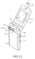
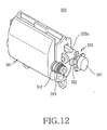
FIG. 11 is a perspective view illustrating a camera lens assembly 300 according to
another embodiment of the present invention and a portable terminal 3 having the
same, and FIG. 12 is a perspective view illustrating the camera lens assembly 300
of the portable terminal 3 as shown in FIG. 11.
The camera lens assembly 300 is different from the camera lens assemblies 200
and 300 of the previous embodiments in that the lens cover is integrally formed
with the lens housing.
When the lens housing 301 is accommodated in a recess 39, the opening 111a and
a flash 11 1b formed at one end of the lens housing 301 are not exposed to the exterior.
The outer peripheral surface of the lens housing 301 matches with the outer
peripheral surface of the body 10, so it seems that the camera lens assembly 300 is
not installed in the portable terminal 3.
The camera lens assembly 300 includes the lens housing 301 and a locking unit
303. The lens housing 301 protrudes out of the body 10 by means of a bias force
of a torsion coil spring 313 installed on a rotating shaft 312 of the lens housing
301.
The rotating shaft 312 extends from one end of the lens housing 301 and is rotatably
coupled with the body 10. One end of the torsion coil spring 313 is supported
on the rotating shaft 312 and the other end of the torsion coil spring 313 is connected
to an inner peripheral surface of the body 10. In a state that the lens housing
301 is accommodated in the recess 39, the torsion coil spring 313 applies a
bias force to the lens housing 301 in such a manner that the lens housing 301 rotatably
protrudes out of the body 10.
The locking unit 303 includes an actuating button 331 and a locking hook 332a.
The actuating button 331 is elastically coupled to an upper side portion of the
body 10 such that the actuating button 331 can be pressed into or may protrude
out from the body 10. One end of the locking hook 332a is preferably bent such
that the end of the locking hook 332a is engaged with the locking recess 121
formed at the lateral portion of the lens housing 301. That is, when the lens housing
301 is accommodated in the recess 39, one end of the locking hook 332a is
engaged with the locking recess 121.
The actuating button 331 is provided at an inner portion thereof with an actuating
protrusion 332. Thus, if the user presses the actuating button 331, the actuating
protrusion 332 presses the other end of the locking hook 332a. The locking hook
332a is rotatably coupled to an inner portion of the body 10 in such a manner that
the locking hook 332a can be rotated. One end of the locking hook 332a may be
separated from the locking recess 121 when the user presses the actuating button
331. As the end of the locking hook 332a is separated from the locking recess
121, a bias force of the torsion coil spring 313 is applied to the lens housing 301
so that the lens housing 301 rotatably protrudes out of the body 10. At this time, a
bias force is also applied to the locking hook 332a in a direction of the locking
recess 121. The bias force applied to the locking hook 332a is transferred to the
actuating button 331 through the other end of the locking hook 332a and the actuating
protrusion 332. Thus, the actuating button 331 protrudes from the lateral
portion of the body 10.
Although it is not illustrated, a rotational range of the lens housing 301 is preferably
limited by the stopper installed on the rotating shaft 312 and the stopper rib
formed in the inner peripheral surface of the body 10. Alternatively, the rotational
range may be limited by installing a stopper, which makes contact with the outer
peripheral portion of the lens housing 301, on the outer peripheral portion of the
body 10. In addition, since the lens housing 301 is rotated by means of the bias
force of the torsion coil spring 313, a frictional unit or a reduction unit including
gears may be provided to reduce the rotational speed of the lens housing 301.
As described above, according to the camera lens assembly and the portable terminal
having the same of embodiments of the present invention, the user opens
the opening to expose the lens housing only when it is necessary to use the camera
lens assembly. That is, the opening is shielded by means of the lens cover when
the camera lens assembly is not in use. Consequently, performance of the camera
element is not degraded by external light. In addition, since the user can easily
open the opening by simply handling the actuating button, so the user can conveniently
use the portable terminal
While the invention has been shown and described with reference to certain embodiments
thereof, it will be understood by those skilled in the art that various
changes in form and details may be made therein without departing from the spirit
and scope of the invention as defined by the appended claims. For instance, although
the locking unit is installed at one side of the lens housing, the locking unit
can be installed at both sides of the lens housing so as to stably maintain the fixing
state. In addition, although the exemplary embodiments utilize the folder type
portable terminal, the camera lens assembly is also applicable for a bar type portable
terminal, a flip type portable terminal, or a sliding type portable terminal. In
addition, an internal antenna can be installed in the portable terminal by utilizing
the space of the lens housing, which is protrudes out of the body, thereby improving
space utilization in the portable terminal.