EP1571794A1 - Method for inversely transforming a signal with respect to a given transfer function - Google Patents
Method for inversely transforming a signal with respect to a given transfer function Download PDFInfo
- Publication number
- EP1571794A1 EP1571794A1 EP04004756A EP04004756A EP1571794A1 EP 1571794 A1 EP1571794 A1 EP 1571794A1 EP 04004756 A EP04004756 A EP 04004756A EP 04004756 A EP04004756 A EP 04004756A EP 1571794 A1 EP1571794 A1 EP 1571794A1
- Authority
- EP
- European Patent Office
- Prior art keywords
- signal
- output signal
- input signal
- preprocessing
- transfer function
- Prior art date
- Legal status (The legal status is an assumption and is not a legal conclusion. Google has not performed a legal analysis and makes no representation as to the accuracy of the status listed.)
- Granted
Links
- 238000000034 method Methods 0.000 title claims abstract description 125
- 238000012546 transfer Methods 0.000 title claims abstract description 47
- 230000001131 transforming effect Effects 0.000 title description 2
- 238000012545 processing Methods 0.000 claims abstract description 67
- 238000007781 pre-processing Methods 0.000 claims abstract description 36
- 238000012804 iterative process Methods 0.000 claims abstract description 28
- 230000009466 transformation Effects 0.000 claims description 27
- 238000004590 computer program Methods 0.000 claims description 5
- 238000011161 development Methods 0.000 claims description 2
- 230000000694 effects Effects 0.000 claims description 2
- 238000011156 evaluation Methods 0.000 claims description 2
- 230000002123 temporal effect Effects 0.000 claims description 2
- 238000013459 approach Methods 0.000 description 12
- 238000010586 diagram Methods 0.000 description 11
- 230000009021 linear effect Effects 0.000 description 9
- 230000005540 biological transmission Effects 0.000 description 3
- 230000003321 amplification Effects 0.000 description 2
- 238000006243 chemical reaction Methods 0.000 description 2
- 230000009022 nonlinear effect Effects 0.000 description 2
- 238000003199 nucleic acid amplification method Methods 0.000 description 2
- 230000003111 delayed effect Effects 0.000 description 1
- 230000001419 dependent effect Effects 0.000 description 1
- 238000013461 design Methods 0.000 description 1
- 230000007274 generation of a signal involved in cell-cell signaling Effects 0.000 description 1
- XZWYZXLIPXDOLR-UHFFFAOYSA-N metformin Chemical compound CN(C)C(=N)NC(N)=N XZWYZXLIPXDOLR-UHFFFAOYSA-N 0.000 description 1
- 230000008054 signal transmission Effects 0.000 description 1
- 230000036962 time dependent Effects 0.000 description 1
Images





Classifications
-
- H—ELECTRICITY
- H04—ELECTRIC COMMUNICATION TECHNIQUE
- H04L—TRANSMISSION OF DIGITAL INFORMATION, e.g. TELEGRAPHIC COMMUNICATION
- H04L27/00—Modulated-carrier systems
- H04L27/01—Equalisers
-
- B—PERFORMING OPERATIONS; TRANSPORTING
- B66—HOISTING; LIFTING; HAULING
- B66F—HOISTING, LIFTING, HAULING OR PUSHING, NOT OTHERWISE PROVIDED FOR, e.g. DEVICES WHICH APPLY A LIFTING OR PUSHING FORCE DIRECTLY TO THE SURFACE OF A LOAD
- B66F7/00—Lifting frames, e.g. for lifting vehicles; Platform lifts
- B66F7/06—Lifting frames, e.g. for lifting vehicles; Platform lifts with platforms supported by levers for vertical movement
- B66F7/065—Scissor linkages, i.e. X-configuration
-
- H—ELECTRICITY
- H04—ELECTRIC COMMUNICATION TECHNIQUE
- H04L—TRANSMISSION OF DIGITAL INFORMATION, e.g. TELEGRAPHIC COMMUNICATION
- H04L25/00—Baseband systems
- H04L25/02—Details ; arrangements for supplying electrical power along data transmission lines
- H04L25/03—Shaping networks in transmitter or receiver, e.g. adaptive shaping networks
- H04L25/03006—Arrangements for removing intersymbol interference
- H04L25/03012—Arrangements for removing intersymbol interference operating in the time domain
- H04L25/03019—Arrangements for removing intersymbol interference operating in the time domain adaptive, i.e. capable of adjustment during data reception
- H04L25/03057—Arrangements for removing intersymbol interference operating in the time domain adaptive, i.e. capable of adjustment during data reception with a recursive structure
-
- H—ELECTRICITY
- H04—ELECTRIC COMMUNICATION TECHNIQUE
- H04L—TRANSMISSION OF DIGITAL INFORMATION, e.g. TELEGRAPHIC COMMUNICATION
- H04L25/00—Baseband systems
- H04L25/02—Details ; arrangements for supplying electrical power along data transmission lines
- H04L25/03—Shaping networks in transmitter or receiver, e.g. adaptive shaping networks
- H04L25/03006—Arrangements for removing intersymbol interference
- H04L25/03343—Arrangements at the transmitter end
-
- H—ELECTRICITY
- H04—ELECTRIC COMMUNICATION TECHNIQUE
- H04L—TRANSMISSION OF DIGITAL INFORMATION, e.g. TELEGRAPHIC COMMUNICATION
- H04L25/00—Baseband systems
- H04L25/02—Details ; arrangements for supplying electrical power along data transmission lines
- H04L25/03—Shaping networks in transmitter or receiver, e.g. adaptive shaping networks
- H04L25/03006—Arrangements for removing intersymbol interference
- H04L2025/03592—Adaptation methods
- H04L2025/03598—Algorithms
- H04L2025/03611—Iterative algorithms
- H04L2025/03617—Time recursive algorithms
-
- H—ELECTRICITY
- H04—ELECTRIC COMMUNICATION TECHNIQUE
- H04L—TRANSMISSION OF DIGITAL INFORMATION, e.g. TELEGRAPHIC COMMUNICATION
- H04L25/00—Baseband systems
- H04L25/02—Details ; arrangements for supplying electrical power along data transmission lines
- H04L25/03—Shaping networks in transmitter or receiver, e.g. adaptive shaping networks
- H04L25/03006—Arrangements for removing intersymbol interference
- H04L2025/03592—Adaptation methods
- H04L2025/03598—Algorithms
- H04L2025/03681—Control of adaptation
Definitions
- the present invention relates to a method for preprocessing a signal and additionally to a method for signal processing according to the preamble of independent claim 16.
- signals have to be received, processed and then afterwards transmitted.
- the received signal is also subject of undesired processes which can produce unwanted distortions in the signal to be transmitted. These distortions may have linear or non-linear form.
- a major drawback of known concepts of equalizing input signals is that in many cases the preprocessing steps are based on an inverse of a transfer function or on an approximation thereof, the transfer function characterizing the respective processing unit. In many cases, the particular structure of the transfer function is not known and/or the respective inverse of said transfer function cannot be established in a simple and reliable manner.
- the object is achieved by a method for preprocessing a signal according to the invention by the characterizing features of independent claim 1.
- the object is also achieved by a method for signal processing of the generic part of independent claim 16 with the characterizing features of claim 16.
- Preferred embodiments of the inventive method for preprocessing a signal and for signal processing are within the scope of the dependent sub claims.
- the inventive method for preprocessing a signal comprises the steps of receiving and/or generating an input signal to be preprocessed, of generating an output signal which is the transformation of said input signal with respect to the inverse of a given transfer function or which is at least an approximation of said transformation, and of outputting said output signal as a preprocessed signal.
- the step of generating said output signal includes an iterative process with at least one iteration. Said at least one iteration comprises a sequence of different processing steps. First of all, a preceding intermediate output signal and said input signal are received.
- a process is applied to said preceding intermediate output signal to cause the preceding intermediate output signal to be completely or approximately transformed according to said given transfer function, thereby generating and providing a transformed preceding intermediate output signal.
- said transformed preceding intermediate output signal is subtracted from said input signal.
- said intermediate error signal or a weighted derivative thereof is added to said intermediate output signal, thereby a succeeding intermediate output signal is generated and provided.
- said input signal is used as said preceding intermediate output signal
- a given succeeding intermediate output signal of the preceding iteration is used as said preceding intermediate output signal for a succeeding iteration.
- the iteration is stopped with the present succeeding intermediate output signal as the output signal of the method.
- the number n of iterations can be controlled by a variety of criteria.
- the number n of iterations of the iterative process is fixed and/or determined in advance.
- the number n of iterations of the iterative process is determined dynamically during said iterative process.
- the number n of iterations of the iterative process can be determined via a stopping condition based on an evaluation of the intermediate error signal and/or its development.
- a stopping condition is defined to be fulfilled, if the intermediate error signal is within a predetermined or a given error range.
- said iterative process, said iterations and/or said transformation process are realized completely or partly by using a digital signal processing means.
- a digital signal processing means In such a case, either digital signals have to be processed and/or processes of analog-digital conversion or digital-analog conversion have to be involved.
- said iterative process, said iterations and/or said transformation process itself can be realized in a software implemented form or manner. This yields a particular high flexibility, in particular for adapting the respective transformation process.
- said iterative process, said iterations and/or said transformation process may be realized in analog form or manner.
- said iterative process, said iterations or said transformation process itself may be realized by using analog signal processing means, for instance an analog calculator or the like.
- the used digital signal processing means and/or the used analog signal processing means are chosen to have or realize said given transfer function or an approximation thereof.
- parts of said iterative process, of said iterations and/or of said transformation process may be realized by a feedback process.
- said iterative process, said iterations, said transformation process itself and/or parts thereof may be realized by parallel processing.
- said input signal, said preceding intermediate output signal and/or said transformed preceding intermediate output signal are processed to have an essentially fixed temporal relationship with respect to each other, in particular by applying appropriate time delay processes.
- said transformation process g is identical an approximation h of said transfer function H or identical to said transfer function H itself.
- Known methods for signal processing comprise a step of receiving and/or generating an input signal to be processed by a processing unit as a primary input signal, a step of preprocessing said primary input signal using a process of equalization, thereby generating a primary output signal, a step of using said primary output signal as a secondary input signal for said processing unit, and a step of processing said secondary input signal using said processing unit and thereby generating and outputting a secondary output signal as an output signal of the method for signal processing. It is known to design the process of equalization to give said primary output signal as said secondary input signal certain signal characteristics so as to obtain a secondary output signal with at least partially reduced or compensated distortion effects by said processing unit compared to non-preprocessed secondary input signals.
- the method for signal processing is characterized in that a method for preprocessing a signal according to the present invention is involved as said step of preprocessing said primary input signal or as a part thereof and/or as said process of equalization and/or as a part thereof. Further, a transfer function of said processing unit or an approximation thereof are used as said transfer function within said method for preprocessing a signal. A primary input signal or a part thereof is used as said input signal for said method for preprocessing a signal. Additionally, an output signal of said method for preprocessing a signal or a part thereof is used as said primary output signal and/or as said secondary input signal or as a part thereof.
- said method for preprocessing a signal and in particular said step of applying the process to the respective input signal or to the preceding intermediate output signal is realized by using said processing unit or a processor which is identical or comparable to said processing unit or a plurality thereof.
- an apparatus for signal processing or for signal preprocessing is provided which is capable of performing the inventive method for preprocessing a signal and/or the steps thereof or the inventive method for signal processing or the steps thereof.
- a computer program product comprising computer product means, which is capable of performing the inventive method for preprocessing a signal and/or the steps thereof or the inventive method for signal processing or the steps thereof when it is executed on a digital signal processing means, a computer, and/or the like.
- a computer readable storage medium comprising computer program product according to the present invention.
- Transmitter amplifiers usually have nonlinear transfer function. Therefore, the transmitter is equalized before the transmission of a signal.
- the invention discloses a very simple iterative approach to equalize a transmitter.
- the method and algorithm are capable of equalizing linear and nonlinear effects of a transmitter.
- An iterative can be approached to linearize nonlinear elements.
- the iterative approach is used to linearize a DRM transmitter.
- a AM/DRM transmitter has a nonlinear transfer function.
- the transfer function is called H(f,t), is if frequency and time dependent. Therefore, the nonlinear transfer function needs to be equalized in the transmitter.
- the transfer function H(f,t) combines all linear and nonlinear effects of the amplifier and, e.g. of an antenna.
- the transfer function depends on the input signal of the transmitter and is therefore time variant.
- This transfer function H is equalized in the equalizer before the amplifier with the inverse transfer function H -1 (f,t).
- the inverse transfer function H -1 does often not exist. In such a case, the inverse transfer function H -1 is approximated with the result of remaining distortions in the transmitted signal.
- the inventive solution uses a similar iterative approach for the transmitter equalization that can be used for a simulcast signal generation.
- the non-linearity is modeled.
- the model is used in the iterative approach to generate an output signal.
- the output signal is compared with a reference signal by means of a subtraction from the delayed reference signal.
- the delay equalizes the group delay of the non-linearity.
- the result of the subtraction represents the error signal after the first iteration.
- the error signal needs to be minimized within the iterative approach to linearize the non-linearity. Therefore, the error signal after the first iteration is multiplied with a weight W and added to the reference signal.
- the so generated signal is the input signal of the second iteration.
- the second iteration again uses the non-linear model to calculate the output signal of the real or physical non-linearity, for example, the DRM transmitter.
- the input signal to the third iteration is calculated in a similar way from the error signal as described above.
- N may be fixed, the error signal is sufficient small.
- the signal called remaining error can be used for tracking the success of the transmitter equalization.
- the output signal is directly input to the non-linearity, i.e. in our example the DRM transmitter.
- the input and output signal can either be a real or a complex signal.
- the non-linearity can be any non-linearity, for example a DRM transmitter, an audio amplifier, or an audio speaker.
- the approach can be used to minimize harmonic distortions in audio power amplifiers, especially for a high output power.
- the harmonic distortions of audio amplifiers increase with increasing output power, so the distortions can be reduced significantly in case of a high output power. As a result, the output power of the amplifier can be increased.
- a state of the art equalizer can be combined with the iterative approach to improve the performance of a state of the art equalizer.
- the approximation of the inverse H -1 of a transfer function H of the non-linearity, e.g. amplifier, calculates a pre-equalized output signal.
- This pre-equalized output signal is input to the iterative approach.
- the iterative equalizer uses the lower path - the DRM signal - as the reference signal in the iterative approach.
- the output signal of the approximation of the inverse transfer function is used as the input signal to the iterative approach.
- the system has further the advantage, that changes in the non-linearity can easily be tracked by the iterative approach. For example, the temperature drift of the non-linearity can easily modeled in the model used in the iterative approach. In the state of the art method, such a tracking is extremely complicated.
- Fig. 1 explains by means of a schematical block diagram the global structure of an embodiment of the inventive method for preprocessing a signal.
- step S1 an input signal I is received or generated.
- step S2 an output signal O is generated based on said received and/or generated input signal I.
- step S3 the output signal O is transmitted or output.
- Fig. 2 shows a more detailed block diagram explaining a possible structure of the step S2 of generating an output signal O according to an embodiment of the method shown in Fig. 1.
- step S21 a preceding intermediate output signal PIO is received.
- Fig. 2 shows a feedback loop structure for the step S2 of generating an output signal O.
- Fig. 3 discloses more details of the process shown in Fig. 2.
- the input signal I and the preceding intermediate output signal PIO are supplied to the process S2 of generating an output signal O.
- the certain process g is applied to the preceding intermediate output signal PIO.
- the transformed preceding intermediate output signal TPIO is first inverted and then the input signal I is added, thereby generating an intermediate error signal IE.
- said intermediate error signal IE is subjected to a weighting function W so as to obtain a weighted intermediate error signal WIE.
- This weighted intermediate error signal WIE is added to said preceding intermediate output signal PIO so as to obtain a succeeding intermediate output signal SIO.
- said iterated succeeding intermediate output signal SIO is used as said output signal O of step S2.
- This output signal O consequently is at least an approximation of the transformation H -1 •I of the input signal I with respect to the inverse H -1 of the given transfer function H.
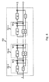
- the iteration of the process of Figs. 2 and 3, i.e. of step S2 for generating an output signal O as shown in Fig. 1 may be realized by a consecutive application of a plurality of processes of Fig. 3 as is shown in Fig. 4.
- a multiplicity of n sub processes S2-1 to S2-n is concatenated so as to realize the global structure of step S2.
- Each of the sub processes S2-1 to S2-n has a structure comparable to step S2 shown in Fig. 3.
- the weighting functions W1 to Wn of the sub process S2-1 to S2-n may be different with respect to each other. Further delay components ⁇ are added to temporarily adjust each of the different signals PIO, TPIO and I in each of the iteration steps 1 to n.
- the input signal I is supplied to the process of step S2 and the output signal O as an approximation of the input signal I transformed by the inverse H -1 of the given transfer function H is output. Additionally, a final error E can be supplied and evaluated to characterize the iteration result performed in step S2.
- Fig. 5 is a block diagram of a known method for signal processing.
- a primary output signal Oprim is obtained and used as a secondary input signal Isec for an amplifier and transmitter stage as a processing unit PU having a transfer function H(f,t).
- a secondary output signal Osec is provided and transmitted.
- Figs. 6 and 7 describe by means of schematical block diagrams fundamental structures of embodiments of the inventive method for signal processing.
- inventive methods for signal processing utilize the inventive method for preprocessing a signal in the context of an iterative equalizer EU as is shown in Figs. 6 and 7.
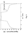
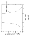
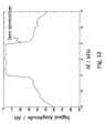
- Figs. 8 to 11 demonstrate by means of diagrams the relationship between different signals utilized in the inventive method for preprocessing a signal and for signal processing.
- the abscissa shows the frequency difference ⁇ f in kHZ as a variation about a given central frequency which is positioned at the value 0.
- the ordinate describes the relative and normalized signal strength or amplitude in dB.
- Fig. 8 demonstrates the input signal I or primary input signal Iprim used in the embodiments described above.
- Fig. 9 shows a prior art secondary output signal Osec, i.e. for the case that no equalization or no sufficient equalization has been performed before the transmitting or amplifying process shown in Fig. 5. Signal distortions are demonstrated.
- Fig. 10 shows the secondary output signal Osec or output signal O after the combined processes of iterative equalization EU and amplification or transmission PU according to the present invention have been performed.
- the signal characteristics before and after passing through the sections shown in Figs. 6 and 7 are the same, i.e. there are only negligible signal distortions added to the secondary output signal Osec if a process of iterative equalization EU according to the present invention has been applied before the step of amplification and transmission PU.
- Fig. 11 is a comparison for the signals of Figs. 8 to 10 to further elucidate the differences and the common features between said signals.
- Fig. 12 shows an the primary output signal Oprim which is to be input into the processing unit PU of Fig. 5 as a secondary input signal Isek.
Landscapes
- Engineering & Computer Science (AREA)
- Computer Networks & Wireless Communication (AREA)
- Signal Processing (AREA)
- Power Engineering (AREA)
- Life Sciences & Earth Sciences (AREA)
- Geology (AREA)
- Mechanical Engineering (AREA)
- Structural Engineering (AREA)
- Transmitters (AREA)
- Amplifiers (AREA)
- Cable Transmission Systems, Equalization Of Radio And Reduction Of Echo (AREA)
- Digital Transmission Methods That Use Modulated Carrier Waves (AREA)
Abstract
Description
- Fig. 1
- is a schematical block diagram of a preferred embodiment of the inventive method for preprocessing a signal.
- Fig. 2-4
- are schematical block diagrams for explaining details of the iteration process.
- Fig. 5
- is a schematical block diagram for explaining a prior art method for signal processing.
- Fig. 6, 7
- are schematical block diagrams for explaining embodiments of the inventive method for signal processing.
- Fig. 8-12
- are diagrams which show different signals used in the inventive methods for a signal processing.
- E
- error, final error
- EU
- equalization unit
- g
- transformation process
- h
- approximation of transfer function H
- H
- transfer function
- H-1
- inverse transfer function
- I
- input signal
- IE
- intermediate error
- Iprim
- primary input signal
- Isec
- secondary input signal
- O
- output signal
- Oprim
- primary output signal
- Osec
- secondary output signal
- PIO
- preceding intermediate output signal
- PU
- processing unit
- SIO
- succeeding intermediate output signal
- TPIO
- transformed preceding intermediate output signal
- W
- weighting function
- W1, ..., Wn
- weighting function
- τ
- delay process
- WIE
- weighted intermediate error
Claims (20)
- Method for preprocessing a signal, in particular a broadcasting signal or the like, comprising the steps of:receiving and/or generating (S1) an input signal (I) to be preprocessed,generating (S2) an output signal (O) which is the transformation (H-1•I) of said input signal (I) with respect to the inverse transfer function (H-1) of a given transfer function (H) or at least an approximation of said transformation (H-1•I), andoutputting (S3) said output signal (O) as a preprocessed signal,wherein an iterative process with at least one iteration is performed within said step (S2) of generating said output signal (O), andwherein each iteration comprises the following steps:receiving (S21) a preceding intermediate output signal (PIO) and said input signal (I),applying (S22) a process (g) to said preceding intermediate output signal (PIO) which causes the preceding intermediate output signal (PIO) to be completely or approximately transformed according to said given transfer function (H), thereby generating and providing a transformed preceding intermediate output signal (TPIO),subtracting (S23) said transformed intermediate output signal (TPIO) from said input signal (I), thereby generating and providing an intermediate error signal (IE), andadding said intermediate error signal (IE) or a weighted derivative thereof to said intermediate output signal (PIO), thereby generating and providing a succeeding intermediate output signal (SIO),wherein in non-initial iterations a succeeding intermediate output signal (SIO) of a preceding iteration is used as said preceding intermediate output signal (PIO) for a succeeding iteration,wherein in the initial iteration said input signal (I) is used as said preceding intermediate output signal (PIO),wherein under a certain stop condition of the iterative process the iteration is stopped with the present succeeding intermediate output signal (SIO) as said output signal (0).
- Method according to any one of the preceding claims,
wherein the number n of iterations of the iterative process (S2) is fixed and/or determined in advance. - Method according to any one of the preceding claims,
wherein the number n of iterations of said iterative process (S2) is determined dynamically during said iterative process (S2). - Method according to claim 3,
wherein the number n of iterations of said iterative process (S2) is determined via a stopping condition based on an evaluation of the intermediate error signal (IE) and/or its development. - Method according to any one of the preceding claims,
wherein a stopping condition is defined to be fulfilled if the intermediate error signal (IE) is within a predetermined or given error range. - Method according to any one of the preceding claims,
wherein said iterative process (S2), said iterations and/or said transformation process (g) are completely or partly realized in digital form or manner. - Method according to any one of the preceding claims,
wherein said iterative process (S2), said iterations and/or said transformation process (g) are realized completely or partly by using digital signal processing means. - Method according to any one of the preceding claims,
wherein said iterative process (S2), said iterations and/or said transformation process (g) are realized in a software implemented form or manner. - Method according to any one of the preceding claims,
wherein said iterative process (S2), said iterations and/or said transformation process (g) are realized in analog form or manner. - Method according to any one of the preceding claims,
wherein said iterative process (S2), said iterations and/or said transformation process (g) are realized by using analog signal processing means. - Method according to any one of the preceding claims,
wherein said digital signal processing means and/or said analog signal processing means are chosen to have or realize said given transfer function (H) or an approximation thereof. - Method according to any one of the preceding claims,
wherein parts of said iterative process (S2), of said iterations and/or of said transformation process (g) are realized by a feedback loop. - Method according to any one of the preceding claims,
wherein said iterative process (S2), said iterations, said transformation process (h) and/or parts thereof are realized by parallel processing. - Method according to any one of the preceding claims,
wherein within said iteration said input signal (I), said preceding intermediate output signal (PIO) and/or said transformed preceding intermediate output signal (TPIO) are processed to have a essentially fixed temporal relationship with respect to each other, in particular by applying appropriate time delay processes. - Method according to any one of the preceding claims,
wherein within said transformation process (g) is identical an approximation (h) of said transfer function (H) or identical to said transfer function (H) itself. - Method for signal processing,
comprising the steps of:characterized inreceiving and/or generating an input signal (I) to be processed by a processing unit (PU) as a primary input signal (Iprim),preprocessing said primary input signal (Iprim) using a process of equalization, therebygenerating a primary output signal (Oprim),using said primary output signal (Oprim) as a secondary input signal (Isec) for said processing unit (PU), andprocessing said secondary input signal (Isec) using said processing unit (PU) therebygenerating and outputting a secondary output signal (Osec) as an output signal,wherein the process of equalization is designed to give said primary output signal (Oprim) as said secondary input signal (Isec) certain signal characteristics so as to obtain a secondary output signal (Osec) with at least partially reduced or compensated distortion effects by said processing unit (PU) compared to non-preprocessed secondary input signals (Isec),that a method for preprocessing a signal according to any one of the preceding claims 1 to 15 is involved as said step of preprocessing (T2) said primary input signal (Iprim) or as a part thereof and/or as said process of equalization and/or as a part thereof,that a transfer function (HPU) of said processing unit (PU) is used as said transfer function (H) within said method for preprocessing a signal,that said primary input signal (Iprim) or a part thereof is used as said input signal (I) for said method for preprocessing a signal, andthat an output signal (O) of said method for preprocessing a signal or a part thereof is used as said primary output signal (Oprim) and/or as said secondary input signal (Isec) or as a part thereof. - Method for signal processing according to claim 16,
wherein said method for preprocessing a signal and in particular said step of applying (S22) a process (h) is realized by using said processing unit (EU, PU) or a processor which is identical or comparable said processing unit (EU) or a plurality thereof. - Apparatus for signal processing or for a signal preprocessing.
which is capable of performing the method for preprocessing a signal according to any one of the preceding claims 1 to 15 or the steps thereof and/or the method for a signal processing according to any one of the preceding claims 16 or 17 or the steps thereof. - Computer program product,
comprising computer program means, which is capable of performing the method for preprocessing a signal according to any one of the preceding claims 1 to 15 and/or the steps thereof or the method for a signal processing according to any one of the preceding claims 16 or 17 or the steps thereof, when it is executed on a digital signal processing means, a computer, and/or the like. - Computer readable storage medium,
comprising a computer program product according to claim 19.
Priority Applications (6)
| Application Number | Priority Date | Filing Date | Title |
|---|---|---|---|
| EP04004756A EP1571794B1 (en) | 2004-03-01 | 2004-03-01 | Method for inversely transforming a signal with respect to a given transfer function |
| DE602004013417T DE602004013417D1 (en) | 2004-03-01 | 2004-03-01 | Method for the inverse transformation of a signal with regard to a predetermined transfer function |
| US11/068,286 US7693922B2 (en) | 2004-03-01 | 2005-02-28 | Method for preprocessing a signal and method for signal processing |
| KR1020050016578A KR20060043248A (en) | 2004-03-01 | 2005-02-28 | Preprocessing Signals and Signal Processing Methods |
| CNB2005100530386A CN100558092C (en) | 2004-03-01 | 2005-03-01 | Method of Preprocessing Signal and Signal Processing Method |
| JP2005056360A JP2005269631A (en) | 2004-03-01 | 2005-03-01 | Signal preprocessing method and signal processing method |
Applications Claiming Priority (1)
| Application Number | Priority Date | Filing Date | Title |
|---|---|---|---|
| EP04004756A EP1571794B1 (en) | 2004-03-01 | 2004-03-01 | Method for inversely transforming a signal with respect to a given transfer function |
Publications (2)
| Publication Number | Publication Date |
|---|---|
| EP1571794A1 true EP1571794A1 (en) | 2005-09-07 |
| EP1571794B1 EP1571794B1 (en) | 2008-04-30 |
Family
ID=34745971
Family Applications (1)
| Application Number | Title | Priority Date | Filing Date |
|---|---|---|---|
| EP04004756A Expired - Lifetime EP1571794B1 (en) | 2004-03-01 | 2004-03-01 | Method for inversely transforming a signal with respect to a given transfer function |
Country Status (6)
| Country | Link |
|---|---|
| US (1) | US7693922B2 (en) |
| EP (1) | EP1571794B1 (en) |
| JP (1) | JP2005269631A (en) |
| KR (1) | KR20060043248A (en) |
| CN (1) | CN100558092C (en) |
| DE (1) | DE602004013417D1 (en) |
Families Citing this family (2)
| Publication number | Priority date | Publication date | Assignee | Title |
|---|---|---|---|---|
| JP5767406B2 (en) | 2011-07-01 | 2015-08-19 | ドルビー ラボラトリーズ ライセンシング コーポレイション | Speaker array equalization |
| GB2541517B (en) | 2015-07-01 | 2021-04-21 | Fellowes Inc | Variable height desktop workstation system |
Citations (1)
| Publication number | Priority date | Publication date | Assignee | Title |
|---|---|---|---|---|
| US6282247B1 (en) * | 1997-09-12 | 2001-08-28 | Ericsson Inc. | Method and apparatus for digital compensation of radio distortion over a wide range of temperatures |
Family Cites Families (8)
| Publication number | Priority date | Publication date | Assignee | Title |
|---|---|---|---|---|
| JPS4871551A (en) * | 1971-12-25 | 1973-09-27 | ||
| JPS58154904A (en) * | 1982-03-10 | 1983-09-14 | Nippon Gakki Seizo Kk | Distortion eliminating circuit |
| JPS6247218A (en) * | 1985-08-23 | 1987-02-28 | Nec Corp | Transmission line switching system |
| GB8826463D0 (en) * | 1988-11-11 | 1988-12-14 | Rca Licensing Corp | Technique for actv side-panel noise reduction |
| US5345406A (en) * | 1992-08-25 | 1994-09-06 | Wireless Access, Inc. | Bandpass sigma delta converter suitable for multiple protocols |
| US6067327A (en) * | 1997-09-18 | 2000-05-23 | International Business Machines Corporation | Data transmitter and method therefor |
| US6242978B1 (en) * | 1999-06-30 | 2001-06-05 | Harris Corporation | Method and apparatus for linearizing an amplifier |
| US6950975B2 (en) * | 2001-08-03 | 2005-09-27 | Combasis Technology, Inc. | Acceleration of convergence rate with verified bits in turbo decoding |
-
2004
- 2004-03-01 EP EP04004756A patent/EP1571794B1/en not_active Expired - Lifetime
- 2004-03-01 DE DE602004013417T patent/DE602004013417D1/en not_active Expired - Lifetime
-
2005
- 2005-02-28 KR KR1020050016578A patent/KR20060043248A/en not_active Withdrawn
- 2005-02-28 US US11/068,286 patent/US7693922B2/en not_active Expired - Fee Related
- 2005-03-01 JP JP2005056360A patent/JP2005269631A/en active Pending
- 2005-03-01 CN CNB2005100530386A patent/CN100558092C/en not_active Expired - Fee Related
Patent Citations (1)
| Publication number | Priority date | Publication date | Assignee | Title |
|---|---|---|---|---|
| US6282247B1 (en) * | 1997-09-12 | 2001-08-28 | Ericsson Inc. | Method and apparatus for digital compensation of radio distortion over a wide range of temperatures |
Also Published As
| Publication number | Publication date |
|---|---|
| KR20060043248A (en) | 2006-05-15 |
| CN100558092C (en) | 2009-11-04 |
| US20050147181A1 (en) | 2005-07-07 |
| US7693922B2 (en) | 2010-04-06 |
| CN1665227A (en) | 2005-09-07 |
| DE602004013417D1 (en) | 2008-06-12 |
| EP1571794B1 (en) | 2008-04-30 |
| JP2005269631A (en) | 2005-09-29 |
Similar Documents
| Publication | Publication Date | Title |
|---|---|---|
| US7269231B2 (en) | System and method for predistorting a signal using current and past signal samples | |
| US10812166B2 (en) | Beam steering digital predistortion | |
| US8670501B2 (en) | Digital pre-distortion of non-linear systems with reduced bandwidth feedback | |
| JP2023509699A (en) | Predistortion method, system, device and storage medium | |
| CN111865228B (en) | A signal distortion pre-correction method, device, system and composite system | |
| US6794939B2 (en) | Signal predistortion using a combination of multiple predistortion techniques | |
| JP4857446B2 (en) | Analog-digital conversion system, analog-digital conversion method, and computer-readable medium | |
| US20170279470A1 (en) | High-frequency signal predistortion device and nonlinear distortion correcting device for power amplifier | |
| EP1560329A1 (en) | Digital predistorter using power series model | |
| US11476809B2 (en) | Polyphase digital signal predistortion in radio transmitter | |
| CN110765720B (en) | A power amplifier predistortion method based on a complex-valued pipeline recurrent neural network model | |
| US8933752B2 (en) | Power amplifier apparatus, distortion compensation coefficient updating method, and transmission apparatus | |
| WO2003092154A1 (en) | The method of improving the radio frequency power amplifier efficiency based on the baseband digital pre-distortion technique | |
| CN103856429A (en) | Adaptive predistortion system and method based on hybrid indirect learning algorithm | |
| WO2023125251A1 (en) | Nonlinear system distortion correction method and apparatus, electronic device, and storage medium | |
| US9712121B2 (en) | Circuits for linearizing an output signal of a non-linear component and related devices and methods | |
| WO2014172849A1 (en) | Transmitter and signal transmission method | |
| CN115913140B (en) | Piecewise polynomial digital predistortion device and method for controlling operation precision | |
| US8648658B2 (en) | Generation of pre-distortion coefficients | |
| EP1571794B1 (en) | Method for inversely transforming a signal with respect to a given transfer function | |
| JPH11330868A (en) | Feedforward linearizer | |
| US8645884B2 (en) | Multi-layer memory structure for behavioral modeling in a pre-distorter | |
| CN103891228B (en) | Disturbance restraining method and device | |
| RU2288550C1 (en) | Method for transferring messages of any physical origin, for example, method for transferring sound messages and system for its realization | |
| JP2005079935A (en) | Adaptive predistortion type distortion compensation power amplifier |
Legal Events
| Date | Code | Title | Description |
|---|---|---|---|
| PUAI | Public reference made under article 153(3) epc to a published international application that has entered the european phase |
Free format text: ORIGINAL CODE: 0009012 |
|
| AK | Designated contracting states |
Kind code of ref document: A1 Designated state(s): AT BE BG CH CY CZ DE DK EE ES FI FR GB GR HU IE IT LI LU MC NL PL PT RO SE SI SK TR |
|
| AX | Request for extension of the european patent |
Extension state: AL LT LV MK |
|
| RAP1 | Party data changed (applicant data changed or rights of an application transferred) |
Owner name: SONY DEUTSCHLAND GMBH |
|
| 17P | Request for examination filed |
Effective date: 20060224 |
|
| AKX | Designation fees paid |
Designated state(s): DE FR GB |
|
| 17Q | First examination report despatched |
Effective date: 20070115 |
|
| RAP1 | Party data changed (applicant data changed or rights of an application transferred) |
Owner name: SONY DEUTSCHLAND GMBH |
|
| GRAP | Despatch of communication of intention to grant a patent |
Free format text: ORIGINAL CODE: EPIDOSNIGR1 |
|
| GRAS | Grant fee paid |
Free format text: ORIGINAL CODE: EPIDOSNIGR3 |
|
| RIN1 | Information on inventor provided before grant (corrected) |
Inventor name: WILDHAGEN, JENS Inventor name: SCHILL, DIETMAR |
|
| GRAA | (expected) grant |
Free format text: ORIGINAL CODE: 0009210 |
|
| AK | Designated contracting states |
Kind code of ref document: B1 Designated state(s): DE FR GB |
|
| REG | Reference to a national code |
Ref country code: GB Ref legal event code: FG4D |
|
| REF | Corresponds to: |
Ref document number: 602004013417 Country of ref document: DE Date of ref document: 20080612 Kind code of ref document: P |
|
| EN | Fr: translation not filed | ||
| PLBE | No opposition filed within time limit |
Free format text: ORIGINAL CODE: 0009261 |
|
| STAA | Information on the status of an ep patent application or granted ep patent |
Free format text: STATUS: NO OPPOSITION FILED WITHIN TIME LIMIT |
|
| 26N | No opposition filed |
Effective date: 20090202 |
|
| PG25 | Lapsed in a contracting state [announced via postgrant information from national office to epo] |
Ref country code: DE Free format text: LAPSE BECAUSE OF FAILURE TO SUBMIT A TRANSLATION OF THE DESCRIPTION OR TO PAY THE FEE WITHIN THE PRESCRIBED TIME-LIMIT Effective date: 20080731 Ref country code: FR Free format text: LAPSE BECAUSE OF FAILURE TO SUBMIT A TRANSLATION OF THE DESCRIPTION OR TO PAY THE FEE WITHIN THE PRESCRIBED TIME-LIMIT Effective date: 20090227 |
|
| GBPC | Gb: european patent ceased through non-payment of renewal fee |
Effective date: 20090301 |
|
| PG25 | Lapsed in a contracting state [announced via postgrant information from national office to epo] |
Ref country code: GB Free format text: LAPSE BECAUSE OF NON-PAYMENT OF DUE FEES Effective date: 20090301 |