EP1571675A2 - Digital control system and method for neutron flux mapping systems - Google Patents
Digital control system and method for neutron flux mapping systems Download PDFInfo
- Publication number
- EP1571675A2 EP1571675A2 EP04016606A EP04016606A EP1571675A2 EP 1571675 A2 EP1571675 A2 EP 1571675A2 EP 04016606 A EP04016606 A EP 04016606A EP 04016606 A EP04016606 A EP 04016606A EP 1571675 A2 EP1571675 A2 EP 1571675A2
- Authority
- EP
- European Patent Office
- Prior art keywords
- detectors
- main control
- path
- nuclear reactor
- detector
- Prior art date
- Legal status (The legal status is an assumption and is not a legal conclusion. Google has not performed a legal analysis and makes no representation as to the accuracy of the status listed.)
- Granted
Links
- 230000004907 flux Effects 0.000 title claims abstract description 186
- 238000000034 method Methods 0.000 title claims abstract description 61
- 238000013507 mapping Methods 0.000 title claims abstract description 56
- 230000004044 response Effects 0.000 claims abstract description 62
- 238000003745 diagnosis Methods 0.000 claims abstract description 34
- 238000004891 communication Methods 0.000 claims description 38
- 238000012544 monitoring process Methods 0.000 claims description 27
- 238000010276 construction Methods 0.000 claims description 24
- 238000012545 processing Methods 0.000 claims description 21
- 238000004364 calculation method Methods 0.000 claims description 15
- 238000012795 verification Methods 0.000 claims description 10
- 230000005236 sound signal Effects 0.000 claims description 7
- 230000002159 abnormal effect Effects 0.000 claims description 6
- 230000002950 deficient Effects 0.000 claims description 4
- 238000003780 insertion Methods 0.000 claims description 3
- 230000037431 insertion Effects 0.000 claims description 3
- 238000010586 diagram Methods 0.000 description 20
- 230000006870 function Effects 0.000 description 14
- 238000010977 unit operation Methods 0.000 description 4
- 238000004458 analytical method Methods 0.000 description 2
- 230000008859 change Effects 0.000 description 2
- 238000013500 data storage Methods 0.000 description 2
- 238000012423 maintenance Methods 0.000 description 2
- 230000008569 process Effects 0.000 description 2
- 238000007792 addition Methods 0.000 description 1
- 230000003321 amplification Effects 0.000 description 1
- 230000003111 delayed effect Effects 0.000 description 1
- 238000005516 engineering process Methods 0.000 description 1
- 238000012986 modification Methods 0.000 description 1
- 230000004048 modification Effects 0.000 description 1
- 238000003199 nucleic acid amplification method Methods 0.000 description 1
- 230000003287 optical effect Effects 0.000 description 1
- 238000006467 substitution reaction Methods 0.000 description 1
Images


Classifications
-
- G—PHYSICS
- G21—NUCLEAR PHYSICS; NUCLEAR ENGINEERING
- G21C—NUCLEAR REACTORS
- G21C17/00—Monitoring; Testing ; Maintaining
- G21C17/10—Structural combination of fuel element, control rod, reactor core, or moderator structure with sensitive instruments, e.g. for measuring radioactivity, strain
- G21C17/108—Measuring reactor flux
-
- A—HUMAN NECESSITIES
- A01—AGRICULTURE; FORESTRY; ANIMAL HUSBANDRY; HUNTING; TRAPPING; FISHING
- A01K—ANIMAL HUSBANDRY; CARE OF BIRDS, FISHES, INSECTS; FISHING; REARING OR BREEDING ANIMALS, NOT OTHERWISE PROVIDED FOR; NEW BREEDS OF ANIMALS
- A01K97/00—Accessories for angling
- A01K97/10—Supports for rods
-
- A—HUMAN NECESSITIES
- A01—AGRICULTURE; FORESTRY; ANIMAL HUSBANDRY; HUNTING; TRAPPING; FISHING
- A01K—ANIMAL HUSBANDRY; CARE OF BIRDS, FISHES, INSECTS; FISHING; REARING OR BREEDING ANIMALS, NOT OTHERWISE PROVIDED FOR; NEW BREEDS OF ANIMALS
- A01K97/00—Accessories for angling
- A01K97/20—Keepnets or other containers for keeping captured fish
-
- Y—GENERAL TAGGING OF NEW TECHNOLOGICAL DEVELOPMENTS; GENERAL TAGGING OF CROSS-SECTIONAL TECHNOLOGIES SPANNING OVER SEVERAL SECTIONS OF THE IPC; TECHNICAL SUBJECTS COVERED BY FORMER USPC CROSS-REFERENCE ART COLLECTIONS [XRACs] AND DIGESTS
- Y02—TECHNOLOGIES OR APPLICATIONS FOR MITIGATION OR ADAPTATION AGAINST CLIMATE CHANGE
- Y02E—REDUCTION OF GREENHOUSE GAS [GHG] EMISSIONS, RELATED TO ENERGY GENERATION, TRANSMISSION OR DISTRIBUTION
- Y02E30/00—Energy generation of nuclear origin
- Y02E30/30—Nuclear fission reactors
-
- Y—GENERAL TAGGING OF NEW TECHNOLOGICAL DEVELOPMENTS; GENERAL TAGGING OF CROSS-SECTIONAL TECHNOLOGIES SPANNING OVER SEVERAL SECTIONS OF THE IPC; TECHNICAL SUBJECTS COVERED BY FORMER USPC CROSS-REFERENCE ART COLLECTIONS [XRACs] AND DIGESTS
- Y10—TECHNICAL SUBJECTS COVERED BY FORMER USPC
- Y10S—TECHNICAL SUBJECTS COVERED BY FORMER USPC CROSS-REFERENCE ART COLLECTIONS [XRACs] AND DIGESTS
- Y10S269/00—Work holders
- Y10S269/907—Work holder for fishing flies
-
- Y—GENERAL TAGGING OF NEW TECHNOLOGICAL DEVELOPMENTS; GENERAL TAGGING OF CROSS-SECTIONAL TECHNOLOGIES SPANNING OVER SEVERAL SECTIONS OF THE IPC; TECHNICAL SUBJECTS COVERED BY FORMER USPC CROSS-REFERENCE ART COLLECTIONS [XRACs] AND DIGESTS
- Y10—TECHNICAL SUBJECTS COVERED BY FORMER USPC
- Y10S—TECHNICAL SUBJECTS COVERED BY FORMER USPC CROSS-REFERENCE ART COLLECTIONS [XRACs] AND DIGESTS
- Y10S81/00—Tools
- Y10S81/01—Tool-support adjuncts
Definitions
- the present invention relates generally to a digital control system and method for neutron flux mapping systems, and more particularly to a digital control system and method for neutron flux mapping systems that is capable of realizing an operation panel of the neutron flux mapping systems, which is provided for acquiring distribution data of a plurality of neutrons inside a nuclear reactor to verify the operating conditions of the nuclear reactor, as an open-ended and standardized system that can be easily maintained and upgraded, providing a graphic user interface (GUI)-based operation interface, and realizing the operation panel of the neutron flux mapping systems on the basis of an event driven operating system so that the operation panel has an operation diagnosis function, an alarm function, and an interlock function as well as an automatic operation function, thereby improving convenience and reliability of the operation.
- GUI graphic user interface
- a neutron flux mapping systems for nuclear reactors serves to measure distribution of neutrons to verify the operation status of a reactor core.
- the neutron flux mapping systems which comprises movable neutron detectors, drivers for respectively driving the detectors, a detector path selector, and a control system, drives the detectors so that the detectors are inserted into the nuclear reactor in regular sequence through a plurality of assigned paths, and records each detector currents produced by means of the neutron, whereby distribution of the neutrons inside the nuclear reactor is measured.
- the control system for neutron flux mapping systems as described above is comprised of relay logic-based instruments, or conventional microprocessor-based instruments.
- Each conventional instrument does not have an open architecture. So, the user should secure maintenance parts dedicated to the respective manufacturer. Also, parts are not easily supplied, as the parts are no longer produced with the change of technology. Consequently, the user may have difficulties in operating and maintaining the control system.
- Operating systems installed in the conventional microprocessor-based instruments are composed of machine language-based programs, such as assembly languages.
- the conventional control system uses a text user interface (TUI)- and procedure driven operating system, whereby verification of the work status and convenience of the operation are not sufficiently supplied.
- TTI text user interface
- the present invention has been made in view of the above problems, and it is an object of the present invention to provide a digital control system and method for neutron flux mapping systems that is capable of realizing an operation panel of the neutron flux mapping systems, which is provided for acquiring distribution data of a plurality of neutrons inside a nuclear reactor to verify the operating conditions of the nuclear reactor, as an open-ended and standardized system that can be easily maintained and upgraded, providing a graphic user interface (GUI)-based operation interface, and realizing the operation panel of the neutron flux mapping systems on the basis of an event driven operating system so that the operation panel has an operation diagnosis function, an alarm function, and an interlock function as well as an automatic operation function, thereby improving convenience and reliability of the operation.
- GUI graphic user interface
- a digital control system for neutron flux mapping systems that enables a plurality of detectors driven by means of a plurality of drivers, respectively, to be inserted into a nuclear reactor in regular sequence through detector paths selected by means of a detector path selector so that distribution of neutrons inside the nuclear reactor is measured to verify the current status of the nuclear reactor
- the digital control system comprises: operation means for outputting an operation control signal using operation information manually set by an operator or prescribed operation information, and collecting and administering flux data transmitted in response to the operation control signal; and main control means for enabling the detectors to be inserted or withdrawn in a prescribed speed and direction through the detector paths in response to the operation control signal of the operation means, collecting and storing neutron distribution data inside the nuclear reactor measured by means of the detectors, and transmitting the neutron distribution data to the operation means.
- a digital control system for neutron flux mapping systems that enables a plurality of detectors driven by means of a plurality of drivers, respectively, to be inserted into a nuclear reactor in regular sequence through detector paths selected by means of a detector path selector so that distribution of neutrons inside the nuclear reactor is measured to verify the current status of the nuclear reactor
- the digital control system comprises: a data communication network; operation means for outputting an operation control signal using operation information manually set by an operator or prescribed operation information through the data communication network, collecting and administering work status information, an alarm, and flux data received through the data communication network in response to the operation control signal, and outputting the collected and administrated operation status information, alarm, and flux data on a screen; monitoring means, having the same construction as the operation means, for monitoring the work status through the data communication network at a remote area, the monitoring means being exclusively usable as the operation means in case of emergency; core physics calculation means for analyzing the status of the core of the nuclear reactor using the flux data received through
- the digital control system for neutron flux mapping systems further comprises: auxiliary control means for enabling the detectors to be emergently inserted or emergently withdrawn in a prescribed speed and direction through the detector paths in a manual mode when the main control means is not available.
- the digital control system for neutron flux mapping systems further comprises: a plurality of acoustic sensors attached to the drivers and the path selector for sensing and outputting the sound signal of the drivers and of the path selector; and field sound control means for processing the detected signal inputted from the acoustic sensors so that the sounds are outputted through a speaker.
- the operation means comprises: a user interface module having a user interface screen for allowing the operator to input operation information thereon; a data transceiver module for transmitting an operation control signal inputted on the user interface screen to the main control means in response to the request of the operation and receiving work status information, an alarm, and flux data from the main control means in response to the operation control signal; and a flux data processing module for collecting the flux data to examine reliability of the flux data, correcting and contracting the examined flux data, and generating the corrected and contracted flux data in the form of a file, a graph, or a numeral so that the flux data is stored, displayed or outputted.
- the operation means has an interface screen for updating the operating system of the main control means in response to the request of the operator, and transmits the operating system of the main control means updated on the interface screen to the main control means so that the operating system stored in the main control means can be updated.
- a digital control method for neutron flux mapping systems that enables a plurality of detectors driven by means of a plurality of drivers, respectively, to be inserted into a nuclear reactor in regular sequence through detector paths selected by means of a detector path selector so that distribution of neutrons inside the nuclear reactor is measured to verify the current status of the nuclear reactor
- the digital control method comprises: an operation control step for outputting an operation control signal using operation information manually set by an operator or prescribed operation information, and collecting and administering flux data transmitted in response to the operation control signal; and a main control step for enabling the detectors to be inserted or withdrawn in a prescribed speed and direction through the detector paths in response to the operation control signal at the operation control step, collecting and storing neutron distribution data inside the nuclear reactor measured by means of the detectors, and transmitting the neutron distribution data to operation means.
- a digital control method for neutron flux mapping systems that enables a plurality of detectors driven by means of a plurality of drivers, respectively, to be inserted into a nuclear reactor in regular sequence through detector paths selected by means of a detector path selector so that distribution of neutrons inside the nuclear reactor is measured to verify the current status of the nuclear reactor
- the digital control method comprises: an operation control step for outputting an operation control signal using operation information manually set by an operator or prescribed operation information through a data communication network, collecting and administering work status information, an alarm, and flux data received through the data communication network in response to the operation control signal, and outputting the collected and administrated operation status information, alarm, and flux data on a screen; a monitoring step, having the same procedure as the operation control step, for monitoring the work status through the data communication network at a remote area, the monitoring step being exclusively usable as the operation control step in case of emergency; a core physics calculation step for analyzing the status of the core of the nuclear reactor using the
- the digital control method for neutron flux mapping systems further comprises: an auxiliary control step for enabling the detectors to be emergently inserted or emergently withdrawn in a prescribed speed and direction through the detector paths in a manual mode when main control means is not available.
- the digital control method for neutron flux mapping systems further comprises: a field sound control step for enabling the detected signal inputted from a plurality of acoustic sensors, attached to the drivers and the path selector for sensing and outputting the sound signal of the drivers and of the path selector; and field sound control means for processing the detected signal inputted from the acoustic sensors so that the sounds are outputted through a speaker.
- the operation control step comprises: a user interface step for providing a user interface screen so that the operator can input operation information on the user interface screen; a data transmitting/receiving step for transmitting an operation control signal inputted on the user interface screen to main control means in response to the request of the operation and receiving work status information, an alarm, and flux data from the main control means in response to the operation control signal; and a flux data processing step for collecting the flux data to examine reliability of the flux data, correcting and contracting the examined flux data, and generating the corrected and contracted flux data in the form of a file, a graph, or a numeral so that the flux data is stored, displayed or outputted.
- the operation control step provides an interface screen for updating the operating system of the main control means in response to the request of the operator
- the digital control method further comprises: a transmitting step for transmitting the operating system of main control means updated on the interface screen to the main control means so that the operating system stored in the main control means can be updated.
- FIG. 1 is a block diagram illustrating a digital control system for neutron flux mapping systems according to a preferred embodiment of the present invention.
- the control system enables a plurality of detectors 23, which are driven by means of a plurality of drivers 22, respectively, to be inserted into a nuclear reactor 40 in regular sequence through detector paths 30 selected by means of a detector path selector 24 so that distribution of neutrons inside the nuclear reactor is measured to verify the current status of the nuclear reactor. As shown in FIG.
- the digital control system comprises: an operation console 10 for outputting an operation control signal using operation information manually set by an operator or prescribed operation information, and collecting and administering flux data transmitted in response to the operation control signal; and a main control unit 21 for enabling the detectors 23 to be inserted or withdrawn in a prescribed speed and direction through the detector paths 30 in response to the operation control signal of the operation console 10, collecting and storing neutron distribution data inside the nuclear reactor measured by means of the detectors 23, and transmitting the neutron distribution data to the operation console 10.
- FIG. 2 is a block diagram illustrating a digital control system for neutron flux mapping systems according to another preferred embodiment of the present invention.
- the control system enables a plurality of detectors 930, which are driven by means of a plurality of drivers 810, respectively, to be inserted into a nuclear reactor in regular sequence through detector paths selected by means of a detector path selector 900 so that distribution of neutrons inside the nuclear reactor is measured to verify the current status of the nuclear reactor. As shown in FIG.
- the digital control system comprises: a data communication network 100; an operation console 200 for outputting an operation control signal using operation information manually set by an operator or prescribed operation information through the data communication network 100, collecting and administering work status information, an alarm, and flux data received through the data communication network 100 in response to the operation control signal, and outputting the collected and administrated operation status information, alarm, and flux data on a screen; a monitoring console 300, having the same construction as the operation console 200, for monitoring the work status through the data communication network 100 at a remote area, the monitoring console 200 being exclusively usable as the operation console 200 in case of emergency; a core physics calculation console 400 for analyzing the status of the core of the nuclear reactor using the flux data received through the data communication network 100; a main control unit 500 for enabling the detectors 930 to be inserted or withdrawn in a prescribed speed and direction through the detector paths in response to the operation control signal of the operation console 200, comparing work status information carried out in response to the operation control signal with an allowable value or a limit value set as
- the drivers 810 are driven in response to control signals transmitted from the main control unit 500 or the auxiliary control unit 600 to an inverter of a local driver control unit 800 for driving a spiral cable connected to the detectors by means of rotation of an electric motor with a helical gear so that the detectors can be inserted into or withdrawn from the inside of the nuclear reactor.
- FIG. 3 is a block diagram illustrating the construction of a main control unit applied to the digital control system for neutron flux mapping systems shown in FIGS. 1 and 2.
- the main control unit comprises a flux data storage means 510, command storage means 515, a main control module 520, a path selector control module 525, an insert control module 530, a scan control module 535, a record control module 540, a withdraw control module 545, a driver run/stop control module 550, a driver direction control module 555, a driver speed control module 560, a flux data acquisition module 565, a detector speed diagnosis module 570, a detector no-motion diagnosis module 575, and a path verification module 580.
- the flux data storage means 510 stores flux data acquired by means of the detectors 23, 930 together with path identification information.
- the command storage means 515 stores the operation control information inputted through the operation console 200 by the operator.
- the main control module 520 determines whether a manual mode, a semi-automatic mode, or an automatic mode is selected, controls the path selector 24, 900 according to a path control command inputted by the operator and controls the drivers 22, 810 according to a driver run/stop control command, a driver direction control command, and a driver speed control command inputted by the operator when the manual mode is selected, controls the path selector 24, 900 according to a path control command inputted by the operator and controls the drivers 22, 810 partially automatically according to an insert control command, a scan control command, a record control command, a withdraw control command inputted by the operator when the semi-automatic mode is selected, initializes a sequence count to determine whether an external interrupt signal exists when the automatic mode is selected, finishes the operation when the external interrupt signal exists, automatically generates a path control command according to a prescribed work sequence to control the path selector 24, 900 and generates an insert control command, a scan control command, a record control command, and a withdraw control command according to a prescribed operation sequence to control the drivers
- the path selector control module 525 selects a detector path in response to a detector path control command inputted manually or automatically from the main control module 520, generates an alarm informing that the detectors are inserted and a path selector stop interlock signal when the current position of the detectors inserted through the detector path is verified and it is determined that the current position of the detectors is above a withdraw limit, receives the current path of the detectors from detector path switches in the path selector, and drives the path selector until the value inputted from the detector path switches is equal to a manually or automatically set detector position command value.
- the path selector control module 525 counts an operation time after the path selector is driven, and generates a path select time-over alarm and a path selector stop interlock signal so that the path selector 24, 900 is not driven when the counted operation time is above a prescribed allowable value.
- the insert control module 530 detects the current position of the detectors 23, 930 using the field sensors 910 and detector position transmitter 940 while enabling the drivers 22, 810 to run in a forward direction at high speed when an insert command of the detectors 23, 930 is issued manually or automatically from the main control module 520, enables the insertion operation of the detectors to be continuously carried out when the current position of the detectors 23, 930 is larger than a withdraw limit value and smaller than the lower limit value of the nuclear reactor, and enables the drivers 22, 810 to be stopped when the current position of the detectors 23, 930 is smaller than the withdraw limit value or larger than the lower limit value of the nuclear reactor.
- the scan control module 535 enables the detectors 23, 930 to scan the inside of the nuclear reactor while enabling the drivers 22, 810 to run in a forward direction at low speed and detects the current position of the detectors using the field sensors 910 and detector position transmitter 940 when a scan command of the detectors 23, 930 is issued manually or automatically from the main control module 520, enables the scan operation of the detectors to be continuously carried out when the current position of the detectors 23, 930 is larger than the lower limit value of the nuclear reactor and smaller than the upper limit value of the nuclear reactor, and enables the drivers 22, 810 to be stopped when the current position of the detectors 23, 930 is smaller than the lower limit value of the nuclear reactor and larger than the upper limit value of the nuclear reactor.
- the record control module 540 enables data acquired by means of the detectors 23, 930 to be received and recorded while enabling the drivers 22, 810 to run in a reverse direction at low speed and detects the current position of the detectors using the field sensors 910 and detector position transmitter 940 when a record command of the detectors 23, 930 is issued manually or automatically from the main control module 520, enables the record operation of the detectors to be continuously carried out when the current position of the detectors 23, 930 is larger than the lower limit value of the nuclear reactor and smaller than the upper limit value of the nuclear reactor, and enables the drivers 22, 810 to be stopped when the current position of the detectors 23, 930 is smaller than the lower limit value of the nuclear reactor and larger than the upper limit value of the nuclear reactor.
- the withdraw control module 545 enables the detectors 23, 930 to be withdrawn while enabling the drivers 22, 810 to run in a reverse direction at high speed and detects the current position of the detectors using the field sensors 910 and detector position transmitter 940 when a withdraw command of the detectors 23, 930 is issued manually or automatically from the main control module 520, enables the scan operation of the detectors to be continuously carried out when the current position of the detectors 23, 930 is larger than a withdraw limit value and smaller than the lower limit value of the nuclear reactor, and enables the drivers 22, 810 to be stopped when the current position of the detectors 23, 930 is smaller than the withdraw limit value and larger than the lower limit value of the nuclear reactor.
- the driver run/stop control module 550 determines whether the path selector 24, 900 is running or not when a run/stop command of the drivers 22, 810 is issued manually or automatically from the main control module 520, generates an alarm and outputs a driver stop interlock signal when the path selector 24, 900 is running, determines whether a calibration path is set in duplicate or not when the path selector 24, 900 is not running, generates an alarm and a driver stop interlock signal when the calibration path is set in duplicate, turns on a run contact in the case that the command from the main control module 520 is a run command when the calibration path is not set in duplicate, and turns off the run contact in the case that the command from the main control module 520 is a stop command when the calibration path is not set in duplicate.
- the driver direction control module 555 enables a forward contact to be turned on so that the drivers 22, 810 can be rotated in a forward direction when a forward rotation command of the drivers is inputted manually or automatically from the main control module 520, and enables a reverse contact to be turned off so that the drivers 22, 810 can be rotated in a reverse direction when a reverse rotation command of the drivers is inputted manually or automatically from the main control module 520.
- the driver speed control module 560 enables a low-speed contact to be turned on so that the drivers 22, 810 can be rotated at low speed when a low-speed rotation command is inputted manually or automatically from the main control module 520, and enables a high-speed contact to be turned on so that the drivers 22, 810 can be rotated at high speed when a high-speed rotation command is inputted manually or automatically from the main control module 520.
- the flux data acquisition module 565 initializes a data count corresponding to the total number of the flux data units, acquires and stores data units one by one, increases the data count, and enables a data acquisition routine to be finished when the data count is above a prescribed limit value.
- the flux data acquisition module 565 is operated so that the data acquisition is carried out by a user or by units of a prescribed data acquisition time.
- the detector speed diagnosis module 570 stores a detector position inputted from the detector position transmitter 940 by units of a prescribed period, subtracts the previous detector position value from the current detector position value, divides the subtraction result value by a prescribed time, calculates the divided result value, i.e., the speed value of the detectors 23, 930 as an absolute speed value, compares the absolute speed value with an allowable lower limit value and an allowable upper limit value, and generates an alarm and outputs a driver stop interlock signal when the absolute speed value is smaller than the allowable lower limit value and larger than the allowable upper limit value.
- the detector no-motion diagnosis module 575 initializes the time and the number of detector storage reel rotation pulses, counts the detector storage reel rotation pulses for a prescribed period of time, continuously performs a detector no-motion diagnosis routine when the number of the rotation pulses is larger than an allowable value, and generates an alarm and outputs a driver stop interlock signal when the number of the rotation pulses is smaller than an allowable value.
- the path verification module 580 calculates a path index corresponding to the current path detected by means of the path switches in the path selector simultaneously when the path selector is operated, determines whether the combination code of the path switches is equal to a prescribed code value for each path index, and considers that the path selector is electrically or mechanically defective and therefore generates a path mismatch alarm and outputs a path selector stop interlock signal when the combination code of the path switches is not equal to the code value.
- FIG. 4 is a block diagram illustrating the construction of an operation console applied to the digital control system for neutron flux mapping systems shown in FIGS. 1 and 2.
- the operation console comprises: a storage unit 210 for storing an operating system of the operation console, a work sequence for measuring distribution of a plurality of neutrons inside the nuclear reactor inputted by an operator, operation information such as an allowable value or a limit value, work status information, an alarm, and data such as flux data; a user signal input unit 220, including a keyboard, mouse and a touch screen, for enabling the user to input the operation information; a control unit 230 for controlling the entire system according to the operating system of the storage unit; a communication interface unit 240 for transmitting and receiving the operation information and the data to and from the system connected through the data communication network 100 in response to the control of the control unit 230; a display unit 250, including a monitor and a touch screen, for displaying the operation information and data on the screen so that the operator can see the operation information and data in response to the control of the control unit 230; an output unit 260, including a printer and a plotter, for outputting the operation information and the data in the form
- the control unit 230 comprises: a user interface module 231 having a user interface screen, on which the operator inputs operation information; a data transceiver module 232 for transmitting an operation control signal inputted on the user interface screen to the main control unit 500 in response to the request of the operation and receiving work status information, an alarm, and flux data from the main control unit 500 in response to the operation control signal; and a flux data processing module 233 for collecting the flux data to examine reliability of the flux data, correcting and contracting the examined flux data, and generating the corrected and contracted flux data in the form of a file, a graph, or a numeral so that the flux data is stored, displayed or outputted.
- the user interface module 231 has various menu items for classifying a plurality of flux paths inside the nuclear reactor into prescribed groups in an automatic operation mode, a semi-automatic operation mode, or a manual operation mode, outputting operation control signals by the prescribed groups to control the path selector and the drivers and to control the output voltage of the detector power supply unit so that the flux data can be acquired, and various display items for displaying work status information, an alarm and flux data by the prescribed groups.
- the user interface module 231 has an automatic operation menu item for automatically selecting detector paths from all flux paths inside the nuclear reactor according to a work sequence prescribed by groups in the automatic operation mode, inserting the detectors into the automatically selected detector paths, scanning and recording the detectors, withdrawing the detectors from the automatically selected detector paths, automatically controlling the voltage of the detectors, and automatically processing the collected flux data.
- the operation console 200 has an interface screen, on which the operating system of the main control unit 500 can be updated in response to the request of the operator, and transmits the updated operating system of the main control unit 500 to the main control unit 500 so that the operating system stored in the main control unit 500 can be updated.
- FIG. 5 is a block diagram illustrating the construction of a monitoring console 300 applied to the digital control system for neutron flux mapping systems shown in FIGS. 1 and 2.
- the monitoring console 300 has the same construction as the operation console 200 except that the monitoring console is installed at a remote area far apart from the place where the work is usually performed by the operator using the operation console 200, and serves to backup the operation console in case of emergency. Therefore, a detailed description of the construction of the monitoring console 300 will not be given.
- FIG. 6 is a block diagram illustrating the construction of a core physics calculation console 400 applied to the digital control system for neutron flux mapping systems shown in FIGS. 1 and 2.
- the core physics calculation console 400 has the same construction as the operation console 200 except that the core physics calculation console 400 further comprises a core physics calculation module 434 for receiving the flux data from the operation console 200 so that the flux data is applied to a core physics calculation program, calculating main variables relevant to safety of the nuclear reactor such as output peak coefficient, quadrant output deviation, and lower/upper output deviation, and providing the analysis result. Therefore, a detailed description of the construction of the core physics calculation console 400 will not be given.
- FIG. 7 is a block diagram illustrating the construction of an auxiliary control unit 600 applied to the digital control system for neutron flux mapping systems according to the present invention.
- the auxiliary control unit 600 comprises: a mode select switch 610 for enabling the operator to set the operation mode to a manual mode or an automatic mode; a direction select switch 620 for selecting the operation mode of the drivers; a speed select switch 630 for selecting the speed mode of the drivers; an emergency stop switch 640 for performing an emergency stop of the drivers; a switching module 615 for enabling the operator to switch the operation mode to an operation condition set using the above-mentioned switches when the main control unit 500 is not available; a driver direction control module 625 for enabling the detectors to be inserted into or withdrawn from the detector paths in response to the control of the switching module 615; a driver speed control module 635 for controlling an insert speed or withdraw speed of the detectors in response to the control of the switching module 615; a driver emergency stop control module for stopping the insert operation or the withdraw operation of the detectors in response to the control of the switching module 615; and a detector proximity sensor 650 for sensing proximity of the detectors to output a detector proximity signal; and
- FIG. 8 is a block diagram illustrating the construction of a field sound control unit 700 applied to the digital control system for neutron flux mapping systems according to the present invention.
- the field sound control unit 700 comprises: filters 701 attached to the plurality of drivers and the path selector for eliminating noise of the sensing signals inputted from the plurality of acoustic sensors 710 that sense and output the sound signal of the drivers and the path selector; an amplifier 703 for converting sensing signals with noise eliminated by means of the filters 701 into acoustic signals, amplifying the acoustic signals to a prescribed level, and outputting the amplified acoustic signal to a speaker 730; and a gain adjuster 702 for adjusting the amplification level of the amplifier 703 according to the manipulation of the operator.
- FIG. 9 is a block diagram illustrating the construction of a detector power supply unit applied to the digital control system for neutron flux mapping systems according to the present invention.
- the detector power supply unit comprises: a filter 800 energized by a commercial AC power (220 VAC) for eliminating noise; a rectifier 801 for rectifying AC voltage with eliminated noise; an amplifier 802 for isolating the rectified voltage and supplying DC voltage to the detector 803; a signal conditioner 807 for converting the DC voltage and outputting the converted DC voltage to a main control unit 808, a voltmeter 809 and recording means 811; a mode select switch 806 for enabling the operator to select a manual mode or an automatic mode; a gain adjuster 804 for receiving a gain adjustment value from the operator when the manual mode is selected by means of the mode select switch 806; and a select unit 810 for outputting a gain adjustment value predetermined by a main control unit 805 to the amplifier 802 when the automatic mode is selected by means of the mode select switch 806.
- a filter 800 energized by a commercial AC power (220 VAC) for eliminating noise
- a rectifier 801 for rectifying AC voltage with eliminated noise
- an amplifier 802
- FIG. 10 is a block diagram illustrating the construction of a detector signal processing unit applied to the digital control system for neutron flux mapping systems according to the present invention.
- the detector signal processing unit comprises: an ammeter 911 for displaying measured current (0 ⁇ 5 mA) inputted from a detector 905 so that the operator can see the measured current; a signal converter 906 for receiving the measured current and converting the measured current into a prescribed voltage (0 ⁇ 100 mV); a filter 907 for eliminating noise from the voltage converted by means of the signal converter 906; an amplifier 908 for amplifying the voltage with noise eliminated by means of the filter 907 to a prescribed level and outputting the amplified voltage to recording means 909 or a main control unit 910; a mode select switch 903 for enabling the operator to select a manual mode or an automatic mode; and a select unit 904 for enabling the signal converter 906 to generate voltage according to a range previously set by means of a manual range selector 901 when the manual mode is selected by means of the mode select switch 903 and enabling the signal converter 906 to generate voltage according to a range previously set by means of a main control unit 902 when the automatic mode is selected by
- a range select signal inputted from the manual range selector 901 or the main control unit 902 is one of 50 uA, 150 uA, 500 uA, 1.5 mA, and 5 mA.
- the signal converter 906 selects one of 2 K ⁇ , 666.6 ⁇ , 200 ⁇ , 66.6 ⁇ , and 20 ⁇ as measured resistance in response to the range select signal.
- a digital control method for neutron flux mapping systems that enables a plurality of detectors, which are driven by means of a plurality of drivers, respectively, to be inserted into a nuclear reactor in regular sequence through detector paths selected by means of a detector path selector so that distribution of neutrons inside the nuclear reactor is measured to verify the current status of the nuclear reactor
- the digital control method comprises: an operation control step for outputting an operation control signal using operation information manually set by an operator or prescribed operation information, and collecting and administering flux data transmitted in response to the operation control signal; and a main control step for enabling the detectors to be inserted or withdrawn in a prescribed speed and direction through the detector paths in response to the operation control signal at the operation control step, collecting and storing neutron distribution data inside the nuclear reactor measured by means of the detectors, and transmitting the neutron distribution data to the operation console.
- the operation console 10 which is capable of performing the above-mentioned digital control method for neutron flux mapping systems according to Embodiment 1 of the present invention, provides a manual mode and an automatic mode.
- the manual mode the operator can set the operation information to a desired value.
- the set operation information is transmitted to the main control unit 21.
- the main control unit 21 controls the operation status of the drivers 22, the detectors 23, and the path selector 24 according to the operation information.
- Each detector 23 is inserted into a predetermined position through a prescribed detector path according to the control of the main control unit 21 so that distribution of the neutrons inside the nuclear reactor is detected.
- the detected result is transmitted to the main control unit 21.
- the main control unit 21 stores the detected result value as flux data, and transmits the detected result value to the operation console 10.
- the flux data is stored, displayed, or outputted so that the current status of the nuclear reactor can be recognized.
- the operation information is generated on the basis of a predetermined value.
- the operation procedure of the automatic mode is identical to that of the manual mode, and therefore a detailed description of the operation procedure of the automatic mode will not be given.
- a digital control method for neutron flux mapping systems that enables a plurality of detectors, which are driven by means of a plurality of drivers, respectively, to be inserted into a nuclear reactor in regular sequence through detector paths selected by means of a detector path selector so that distribution of neutrons inside the nuclear reactor is measured to verify the current status of the nuclear reactor
- the digital control method comprises: an operation control step for outputting an operation control signal using operation information manually set by an operator or prescribed operation information through the data communication network, collecting and administering work status information, an alarm, and flux data received through the data communication network in response to the operation control signal, and outputting the collected and administrated operation status information, alarm, and flux data on a screen; a monitoring step, having the same procedure as the operation control step, for monitoring the work status through the data communication network at a remote area, the monitoring step being exclusively usable as the operation control step in case of emergency; a core physics calculation step for analyzing the status of the core of the nuclear reactor using
- the digital control system which is capable of performing the above-mentioned digital control method for neutron flux mapping systems according to Embodiment 2 of the present invention, further comprises the monitoring console 300, the core physics calculation console 400, the auxiliary control unit 600, and the field sound control unit 700.
- the monitoring console 300 is installed at an office room or at remote area.
- the monitoring console 300 enables the operator or the administrator to monitor the work status through the data communication network 100 at the office or at the remote area.
- the monitoring console 300 can be used as a substitute of the operation console 200 when the operation console 200 is inoperable.
- the core physics calculation console 400 is connected to the data communication network 100, especially a communication network of a power plant so that flux data collected from the neutron flux mapping system and a computer in the power plant is applied to a core physics calculation program.
- Main variables relevant to safety of the nuclear reactor such as output peak coefficient, quadrant output deviation, and lower/upper output deviation are calculated and the analysis result is provided by means of the core physics calculation console 400.
- the auxiliary control unit 600 enables the control mode to be switched to the manual mode by means of the mode select switch 610 when the main control unit 500 is not available.
- the detectors are emergently inserted or emergently withdrawn in a prescribed speed and direction through the detector paths in the manual mode by means of the direction select switch 620, the speed select switch 630, and the emergency stop switch 640.
- the acoustic sensors 710 are attached to the drivers 810 and the path selector 900 for sensing mechanical movement generated at the drivers 810 and of the path selector 900 and outputting the detected signal to the field sound control unit 700.
- the detected signal is inputted to the filter 701 of the field sound control unit 700 where noise is eliminated from the detected signal.
- the signal with eliminated noise is converted into an acoustic signal and amplified by means of the amplifier 703.
- the sound signal is finally outputted to the speaker 730 so that the operator can hear the operation sounds from the instruments operated at the work field.
- a skilled operator can determine whether the field instruments are normally operated or not on the basis of patterns of the operation sounds, whereby the operation and the maintenance of the instruments can be efficiently carried out.
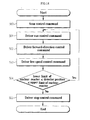
- FIG. 11 is a flowchart illustrating a main control routine of the main control unit according to the present invention.
- allowable and limit values are set by the operator at an environment setting step (S1), the measuring sequence of the paths is set at a path measuring sequence setting step (S2), and it is determined by means of the main control module 520 of the main control unit 500 whether the manual mode is selected or not (S3).
- the path selector 900 is controlled according to a path control command inputted by the operator, and the drivers 810 are controlled according to a driver run/stop control command, a driver direction control command, and a driver speed control command inputted by the operator (S4).
- the path selector 900 is controlled according to a path control command inputted by the operator, and the drivers 810 are controlled according to an insert control command, a scan control command, a record control command, and a withdraw control command inputted by the operator so that the detectors can be partially automatically operated by sections (S6).
- Step S5 When it is determined that the automatic mode is selected at Step S5, a sequence count is initialized (S7) , and it is determined whether an external interrupt signal exists or not (S8). When it is determined that the external interrupt signal does not exist, a path control command is automatically generated according to a prescribed work sequence to control the path selector, and an insert control command, a scan control command, a record control command, and a withdraw control command are generated according to a prescribed work sequence to control the drivers so that the detectors can be automatically operated (S9).
- FIG. 12 is a flowchart illustrating a path selector control routine of the main control unit according to the present invention.
- the path selector control module 525 selects detector paths in response to a path control command inputted manually or automatically from the main control module 520, and determines the current position of the detectors inserted through the detector paths (S21).
- the current path of the detectors is inputted to the path selector control module 525 from the path switches in the path selector (S22), and the time is initialized (S23).
- the path selector is operated (S27). At this time, the time is counted (S28) so that the path selector can be operated for a prescribed period of time.
- an alarm signal informing that the path select time is over i.e., a path select time-over alarm
- a path selector stop interlock signal is generated (S32).
- FIG. 13 is a flowchart illustrating an insert control routine of the main control unit according to the present invention.
- the insert control module 530 senses the current position of the detectors using the field sensors 910 and detector position transmitter 940 while the insert control module 530 controls the drivers so that the drivers can run in a forward direction at high speed, and compares the current position of the detectors with a prescribed limit value (S44).
- Step S44 When the current position of the detectors is larger than the withdraw limit value and smaller than the lower limit value of the nuclear reactor at Step S44, the procedure returns to Step S41, and then the drivers are controlled so that the above-mentioned operations are repeatedly performed from Step S41.
- Step S44 When the current position of the detectors is smaller than the withdraw limit value and larger than the lower limit value of the nuclear reactor at Step S44, on the other hand, a control command is outputted so that the drivers are stopped (S45) .
- FIG. 14 is a flowchart illustrating a scan control routine of the main control unit according to the present invention.
- the scan control module 535 enables the detectors to scan the inside of the nuclear reactor while the scan control module 535 controls the drivers so that the drivers can run in a forward direction at low speed, senses the current position of the detectors using the field sensors 910 and detector position transmitter 940, and compares the current position of the detectors with a prescribed limit value (S64).
- Step S64 When the current position of the detectors is larger than the lower limit value of the nuclear reactor and smaller than the upper limit value of the nuclear reactor at Step S64, the procedure returns to Step S61, and then the drivers are controlled so that the above-mentioned operations are repeatedly performed from Step S61.
- Step S65 When the current position of the detectors is smaller than the lower limit value of the nuclear reactor and larger than the upper limit value of the nuclear reactor at Step S64, on the other hand, a control command is outputted so that the drivers are stopped (S65).
- FIG. 15 is a flowchart illustrating a record control routine of the main control unit according to the present invention.
- the record control module 540 enables data acquired by means of the detectors to be received and recorded while the record control module 540 controls the drivers so that the drivers can run in a reverse direction at low speed, senses the current position of the detectors using the field sensors 910 and detector position transmitter 940, and compares the current position of the detectors with a prescribed limit value (S85).
- Step S85 When the current position of the detectors is larger than the lower limit value of the nuclear reactor and smaller than the upper limit value of the nuclear reactor at Step S85, the procedure returns to Step S81, and then the drivers are controlled so that the above-mentioned operations are repeatedly performed from Step S81, and thus the record operation of the detectors can be continuously carried out.
- Step S85 When the current position of the detectors is smaller than the lower limit value of the nuclear reactor and larger than the upper limit value of the nuclear reactor at Step S85, on the other hand, a control command is outputted so that the drivers are stopped (S86).
- FIG. 16 is a flowchart illustrating a withdraw control routine of the main control unit according to the present invention.
- the withdraw control module 545 senses the current position of the detectors using the field sensors 910 and detector position transmitter 940 while the withdraw control module 545 controls the drivers so that the drivers can run in a reverse direction at high speed, and compares the current position of the detectors with a prescribed limit value (S105).
- Step S105 When the current position of the detectors is larger than the withdraw limit value and smaller than the lower limit value of the nuclear reactor at Step S105, the procedure returns to Step S102, and then the drivers are controlled so that the above-mentioned operations are repeatedly performed from Step S102.
- Step S105 When the current position of the detectors is smaller than the withdraw limit value and larger than the lower limit value of the nuclear reactor at Step S105, on the other hand, a control command is outputted so that the drivers are stopped (S106).
- FIG. 17 is a flowchart illustrating a driver run/stop control routine of the main control unit according to the present invention.
- driver run/stop control command is issued manually or automatically by means of the main control module 520 (S121), as shown in FIG. 17, it is determined by the driver run/stop control module 550 whether the path selector is running or not (S122).
- the driver run/stop control module 550 When it is determined that the path selector is running at Step S122, the driver run/stop control module 550 generates an alarm (S123), and outputs a driver stop interlock signal (S124).
- the driver run/stop control module 550 determines whether a calibration path is set in duplicate or not (S125). When it is determined that the calibration path is set in duplicate, the driver run/stop control module 550 generates an alarm (S126), and outputs a driver stop interlock signal (S127).
- the driver run/stop control module 550 turns on a run contact in the case that the command from the main control module 520 is a run command of the detectors (S129), and turns off the run contact in the case that the command from the main control module 520 is a stop command for the detectors (S130).
- FIG. 18 is a flowchart illustrating a driver direction control routine of the main control unit according to the present invention.
- driver direction control command is issued manually or automatically by means of the main control module 520 (S141), as shown in FIG. 18, it is determined by the driver direction control module 555 whether a forward rotation command of the drivers is inputted or a reverse rotation command of the drivers is inputted (S142).
- the driver direction control module 555 When it is determined that the forward rotation command of the drivers is inputted at Step S142, the driver direction control module 555 enables a reverse contact to be turned off (S143) and a forward contact to be turned on (S144) so that the drivers can be rotated in a forward direction.
- the driver direction control module 555 enables the forward contact to be turned off (S145) and the reverse contact to be turned on (S146) so that the drivers can be rotated in a reverse direction.
- FIG. 19 is a flowchart illustrating a driver speed control routine of the main control unit according to the present invention.
- driver speed control command is issued manually or automatically by means of the main control module 520 (S161), as shown in FIG. 19, it is determined by the driver speed control module 560 whether a high-speed rotation command of the drivers is inputted or a low-speed rotation command of the drivers is inputted (S162).
- the driver speed control module 560 When it is determined that the low-speed rotation command of the drivers is inputted at Step S162, the driver speed control module 560 enables a high-speed contact to be turned off (S163) and a low-speed contact to be turned on (S164) so that the drivers can be rotated at low speed.
- the driver speed control module 560 enables the low-speed contact to be turned off (S165) and the high-speed contact to be turned on (S166) so that the drivers can be rotated at high speed.
- FIG. 20 is a flowchart illustrating a flux data acquisition routine of the main control unit according to the present invention.
- the flux data acquisition module 565 When a flux data acquisition command is issued manually or automatically by means of the main control module 520 (S180), as shown in FIG. 20, the flux data acquisition module 565 initializes a data count corresponding to the total number of the flux data units (S181), acquires and stores data units one by one (S182).
- the flux data acquisition module 565 determines whether the data count is above a prescribed limit value or not (S183). When it is determined that the data count is above the prescribed limit value at Step S183, the data acquisition routine is finished (all data has been acquired). When it is determined that the data count is below the prescribed limit value at Step S183, on the other hand, the flux data acquisition module 565 increases the data count (S184), initializes a time count (S185), and determines whether time is above a prescribed allowable value or not (S186).
- the flux data acquisition module 565 When it is determined that the time is below the prescribed allowable value at Step S186, the flux data acquisition module 565 repeatedly carries out Step S186 while counting time (S187). When it is determined that the time is above the prescribed allowable value at Step S186, on the other hand, the flux data acquisition module 565 repeatedly carries out Step S182 to continuously collect flux data from the detectors.
- FIG. 21 is a flowchart illustrating a detector speed diagnosis routine of the main control unit according to the present invention.
- the detector speed diagnosis module 570 initializes time (S200), and stores a previous detector position (S201).
- the detector speed diagnosis module 570 counts time (S202), and determines whether the time is above a prescribed value or not (S203). When it is determined that the time is below the prescribed value at Step S203, the detector speed diagnosis module 570 carries out Step 202 so that it is delayed for a prescribed period of time.
- the detector speed diagnosis module 570 stores a current detector position inputted from the detector position transmitter 940 (S204), subtracts the previous detector position value from the current detector position value, divides the subtraction result value by the prescribed time, calculates the divided result value, i.e., the speed value of the detectors as an absolute speed value (S205).
- the detector speed diagnosis module 570 determines whether the absolute speed value is larger than an allowable lower limit value and smaller than an allowable upper limit value (S206). When it is determined that the absolute speed value is smaller than the allowable lower limit value and larger than the allowable upper limit value at Step 206, the detector speed diagnosis module 570 generates an alarm signal (S207), and outputs a driver stop interlock signal (S208).
- the detector speed diagnosis module 570 When it is determined that the absolute speed value is larger than the allowable lower limit value and smaller than the allowable upper limit value at Step 206, on the other hand, the detector speed diagnosis module 570 repeatedly carries out the procedure from Step S200.
- FIG. 22 is a flowchart illustrating a detector no-motion diagnosis routine of the main control unit according to the present invention.
- the detector no-motion diagnosis module 575 initializes time and the number of detector storage reel rotation pulses (S220 and S221), and determines whether the time is larger than a prescribed value (S222).
- the detector no-motion diagnosis module 575 When it is determined that the time is smaller than the prescribed value at Step S222, the detector no-motion diagnosis module 575 counts the number of detector storage reel rotation pulses (S223), and then counts time (S224). Subsequently, Step S222 is carried out again so that it is determined by the detector no-motion diagnosis module 575 whether the counted time is larger than the prescribed value or not.
- the detector no-motion diagnosis module 575 determines whether the counted number of the rotation pulses is larger than a prescribed allowable value or not (S225). When it is determined that the counted number of the rotation pulses is smaller than the prescribed allowable value at Step S225, the detector no-motion diagnosis module 575 generates an alarm signal (S226), and outputs a driver stop interlock signal (S227). When it is determined that the counted number of the rotation pulses is larger than the prescribed allowable value at Step S225, on the other hand, the detector no-motion diagnosis module 575 repeatedly carries out the procedure from Step S220.
- FIG. 23 is a flowchart illustrating a path verification routine of the main control unit according to the present invention.
- the path verification module 580 calculates a path index (S242) corresponding to the current path detected by means of the path switches in the path selector (S241), and determines whether the combination code of the path switches is equal to a prescribed code value or not for each path index (S243).
- the path verification module 580 When it is determined that the combination code of the path switches is not equal to the prescribed code value at Step S243, the path verification module 580 considers that the path selector is electrically or mechanically defective, and therefore generates a path mismatch alarm (S248) and outputs a path selector stop interlock signal (S249) .
- Step S243 is repeatedly carried out provided that the inputted value of a path selector cam switch, which is designed to be turned off when each path selection is completed, is "on".
- the path index is increased (S245), and it is determined whether the path index is larger than the total number of paths (S246).
- Step S243 is repeatedly carried out.
- the position index is initialized (S237), and Step S243 is repeatedly carried out.
- FIG. 24 is a view showing a manual mode operation screen of the operation console according to the present invention.
- the manual mode operation screen is a user interface screen provided to an operator through the operation console 200 when the operator is to perform necessary operations in a manual mode.
- the manual mode operation screen comprises an operation status display section 1, on which work groups, work paths, operation modes, and sensor operations are displayed, a detector current display section 2, a system alarm display section 3, a system status display section 4, an operation indicating section 5, computer on/off select buttons 6, automatic/semi-automatic/manual mode select buttons 7, driver A/B/C/D select buttons 8, an outside path selector operation screen call button 9, an inside path selector operation screen call button 10, speed select buttons 11, insert/stop/withdraw select buttons 12.
- the operator manually specifies the driver direction select, the driver speed select, and the detector path select, all of which are specified to drive the detectors as described above.
- the operation can be carried out irrespective of upper and lower limit values of the nuclear reactor.
- the manual mode is suitable when functions of the detectors, the drivers, and the path selector are to be simply tested, when the detectors are to be operated to verify the upper and lower limit values of the nuclear reactor, or when emergency operation is to be carried out on the basis of the determination of the operator.
- FIG. 25 is a view showing a semi-automatic mode operation screen of the operation console according to the present invention.
- the semi-automatic mode operation screen is a user interface screen provided to an operator through the operation console 200 when the operator is to perform necessary operations in a semi-automatic mode.
- the semi-automatic mode operation screen includes insert/scan/record/stop select buttons 20.
- the operator manually specifies selection of the detector paths, through which the detectors are to be inserted, and operation of the detectors by sections, as described above. After the selection of the detector paths, the insert, scan, record, and withdraw operations of the detectors are partially automatically carried out according to the upper and lower limit values of the nuclear reactor. At this time, the direction and speed of the detectors are automatically selected on the basis of modes.
- the semi-automatic mode is suitable when any supplementary work is necessary after works have been finished according to the automatic mode operation or it is difficult to carry out the automatic mode operation.
- FIG. 26 is a view showing an automatic mode operation screen of the operation console according to the present invention.
- the automatic mode operation screen is a user interface screen provided to an operator through the operation console 200 when the operator is to perform necessary operations in an automatic mode.
- the automatic mode operation screen includes a start/stop button 30, a pause button 31, and a work progress display window 32.
- FIG. 27 is a view showing an inside path selector operation screen of the operation console according to the present invention.
- the inside path selector operation screen is a user interface screen provided to an operator through the operation console 200 when the operator is to manually operate the inside path selector.
- the inside path selector operation screen includes path select buttons 40, position indicating lamps 41, a status information display section 42, and time-out reset buttons 43. Twelve paths are provided in all. Ten work paths, a calibration path, and a storage paths can be selected by groups.
- the inside path selector operation screen is suitably used when path changing works are to be carried out in the manual mode or in the semi-automatic mode.
- FIG. 28 is a view showing an outside path selector operation screen of the operation console according to the present invention.
- the outside path selector operation screen is a user interface screen provided to an operator through the operation console 200 when the operator is to manually operate the outside path selector.
- the outside path selector operation screen includes instrument operation lamps 50, position indicating lamps 51, a status information display section 52, a run button 53, direction select button 54, and a time-out reset button 55.
- the inside path selectors four in all, are individually rotated in a clockwise direction or in a counterclockwise direction so that each detector can perform nuclear measuring in an adjacent work group in addition to the original work group.
- the outside path selector provides a normal mode, a first emergency mode, a second emergency mode, and a third emergency mode on the basis of rotated positions of the inside path selectors.
- FIG. 29 is a view showing a detector power supply unit operation screen of the operation console according to the present invention.
- the detector power supply unit operation screen is a user interface screen provided to an operator through the operation console 200 when the operator is to set the voltage of power supplied to the detectors, and simultaneously to display the measured current data.
- the detector power supply unit operation screen includes voltage set buttons 60, current range set buttons 61, status information display sections 62, and an alarm display section 63.
- FIG. 30 is a flowchart illustrating a flux data processing routine of the operation console according to the present invention.
- the flux data processing routine is a routine that is automatically carried out during operation to process flux data collected by means of the operation console 200.
- Flux data is collected from the main control unit 500 through the data transceiver module 232 (S240 - S241), and reliability of the flux data is examined (S242).
- the flux data is corrected (S243), and is then contracted (S244).
- the flux data is stored in the form of a file, a graph, or a numeral so that the flux data is stored (S245), displayed (S246) or outputted (S247).
- the operating system routines used in the main control unit 500 and the operation console 200 are separated from one another by detailed functions. Also, the process of each routine is defined by the event driven system. Consequently, the present invention does not need an operation initialization set procedure due to change of the operation mode, which is necessary for the procedure driven system, in various operation conditions caused in the manual mode, the semi-automatic mode, and the automatic mode, whereby it is possible for an operator to operate more easily and conveniently.
- the present invention provides a digital control system and method for neutron flux mapping systems that is capable of realizing an operation panel of the neutron flux mapping systems, which is provided for acquiring distribution data of a plurality of neutrons inside a nuclear reactor to verify the operating conditions of the nuclear reactor, as an open-ended and standardized system that can be easily maintained and upgraded, providing a graphic user interface (GUI)-based operation interface, and realizing the operation panel of the neutron flux mapping systems on the basis of an event driven operating system so that the operation panel has an operation diagnosis function, an alarm function, and an interlock function as well as an automatic operation function, thereby improving convenience and reliability of the operation.
- GUI graphic user interface
Abstract
Description
Claims (46)
- A digital control system for neutron flux mapping systems that enables a plurality of detectors driven by means of a plurality of drivers, respectively, to be inserted into a nuclear reactor in regular sequence through detector paths selected by means of a detector path selector so that distribution of neutrons inside the nuclear reactor is measured to verify the current status of the nuclear reactor, wherein the digital control system comprises:operation means for outputting an operation control signal using operation information manually set by an operator or prescribed operation information, and collecting and administering flux data transmitted in response to the operation control signal; andmain control means for enabling the detectors to be inserted or withdrawn in a prescribed speed and direction through the detector paths in response to the operation control signal of the operation means, collecting and storing neutron distribution data inside the nuclear reactor measured by means of the detectors, and transmitting the neutron distribution data to the operation means.
- A digital control system for neutron flux mapping systems that enables a plurality of detectors driven by means of a plurality of drivers, respectively, to be inserted into a nuclear reactor in regular sequence through detector paths selected by means of a detector path selector so that distribution of neutrons inside the nuclear reactor is measured to verify the current status of the nuclear reactor, wherein the digital control system comprises:a data communication network;operation means for outputting an operation control signal using operation information manually set by an operator or prescribed operation information through the data communication network, collecting and administering work status information, an alarm, and flux data received through the data communication network in response to the operation control signal, and outputting the collected and administrated operation status information, alarm, and flux data on a screen;monitoring means, having the same construction as the operation means, for monitoring the work status through the data communication network at a remote area, the monitoring means being exclusively usable as the operation means in case of emergency;core physics calculation means for analyzing the status of a core of the nuclear reactor using the flux data received through the data communication network; andmain control means for enabling the detectors to be inserted or withdrawn in a prescribed speed and direction through the detector paths in response to the operation control signal of the operation means, comparing work status information carried out in response to the operation control signal with an allowable value or a limit value set as the operation information to diagnose the operation status information, outputting an interlock signal and an alarm signal to protect the instruments when an abnormal condition occurs, collecting neutron distribution data inside the nuclear reactor measured by means of the detectors and storing the neutron distribution data as flux data, and transmitting the work status information, the alarm, and the flux data through the data communication network.
- The system as set forth in claim 1 or 2, further comprising:auxiliary control means for enabling the detectors to be emergently inserted or emergently withdrawn in a prescribed speed and direction through the detector paths in a manual mode when the main control means is not available.
- The system as set forth in claim 1 or 2, further comprising:a plurality of acoustic sensors attached to the drivers and the path selector for sensing and outputting the sound signal of the drivers and of the path selector; andfield sound control means for processing the detected signal inputted from the acoustic sensors so that the sounds are outputted through a speaker.
- The system as set forth in claim 1 or 2, wherein the main control means includes a main control module for determining whether a manual mode, a semi-automatic mode, or an automatic mode is selected, controlling the path selector according to a path control command inputted by the operator and controlling the drivers according to a driver run/stop control command, a driver direction control command, and a driver speed control command inputted by the operator when the manual mode is selected, controlling the path selector according to a path control command inputted by the operator and controlling the drivers partially automatically according to an insert control command, a scan control command, a record control command, and a withdraw control command inputted by the operator when the semi-automatic mode is selected, initializing a sequence count to determine whether an external interrupt signal exists when the automatic mode is selected, finishing the operation when the external interrupt signal exists, automatically generating a path control command according to a prescribed work sequence to control the path selector and automatically generating an insert control command, a scan control command, a record control command, and a withdraw control command according to a prescribed operation sequence to control the drivers when the external interrupt signal does not exist, finishing the work when the sequence count is larger than a prescribed limit value, and increasing the sequence count so that the operation is repeatedly performed according to a next work sequence when the sequence count is not larger than the prescribed limit value.
- The system as set forth in claim 5, wherein the main control means includes a path selector control module for selecting a detector path in response to a path control command inputted manually or automatically from the main control module, generating an alarm informing that the detectors are inserted and a path selector stop interlock signal when the current position of the detectors is verified by means of the detector position transmitter and it is determined that the current position of the detectors is above a withdraw limit, receiving the current path of the detectors from the path switches in the path selector, and driving the path selector until the value inputted from the path switches is equal to a manually or automatically set path command value.
- The system as set forth in claim 6, wherein the path selector control module counts an operation time after the path selector is driven, and generates a path select time-over alarm and a path selector stop interlock signal so that the path selector is not driven when the counted operation time is above a prescribed allowable value.
- The system as set forth in claim 5, wherein the main control means includes an insert control module for detecting the current position of the detectors through the use of field sensors and detector position transmitter while enabling the drivers to run in a forward direction at high speed when an insert command of the detectors is issued manually or automatically from the main control module, enabling the insertion operation of the detectors to be continuously carried out when the current position of the detectors is larger than a withdraw limit value and smaller than the lower limit value of the nuclear reactor, and enabling the drivers to be stopped when the current position of the detectors is smaller than the withdraw limit value or larger than the lower limit value of the nuclear reactor.
- The system as set forth in claim 5, wherein the main control means includes a scan control module for enabling the detectors to scan the inside of the nuclear reactor while enabling the drivers to run in a forward direction at low speed and detects the current position of the detectors through the use of field sensors and detector position transmitter when a scan command of the detectors is issued manually or automatically from the main control module, enabling the scan operation of the detectors to be continuously carried out when the current position of the detectors is larger than the lower limit value of the nuclear reactor and smaller than the upper limit value of the nuclear reactor, and enabling the drivers to be stopped when the current position of the detectors is smaller than the lower limit value of the nuclear reactor and larger than the upper limit value of the nuclear reactor.
- The system as set forth in claim 5, wherein the main control means includes a record control module for enabling data acquired by means of the detectors to be received and recorded while enabling the drivers to run in a reverse direction at low speed and detecting the current position of the detectors through the use of field sensors and detector position transmitter when a record command of the detectors is issued manually or automatically from the main control module, enabling the record operation of the detectors to be continuously carried out when the current position of the detectors is larger than the lower limit value of the nuclear reactor and smaller than the upper limit value of the nuclear reactor, and enabling the drivers to be stopped when the current position of the detectors is smaller than the lower limit value of the nuclear reactor and larger than the upper limit value of the nuclear reactor.
- The system as set forth in claim 5, wherein the main control means includes a withdraw control module for enabling the detectors to be withdrawn while enabling the drivers to run in a reverse direction at high speed and detecting the current position of the detectors through the use of field sensors and detector position transmitter when a withdraw command of the detectors is issued manually or automatically from the main control module, enabling the scan operation of the detectors to be continuously carried out when the current position of the detectors is larger than a withdraw limit value and smaller than the lower limit value of the nuclear reactor, and enabling the drivers to be stopped when the current position of the detectors is smaller than the withdraw limit value and larger than the lower limit value of the nuclear reactor.
- The system as set forth in claim 5, wherein the main control means includes a driver run/stop control module for determining whether the path selector is running or not when a run/stop command of the drivers is issued manually or automatically from the main control module, generating an alarm and outputting a driver stop interlock signal when the path selector is running, determining whether a calibration path is set in duplicate or not when the path selector is not running, generating an alarm and a driver stop interlock signal when the calibration path is set in duplicate, turning on a run contact in the case that the command from the main control module is a run command when the calibration path is not set in duplicate, and turning off the run contact in the case that the command from the main control module is a stop command when the calibration path is not set in duplicate.
- The system as set forth in claim 5, wherein the main control means includes:a driver direction control module for enabling a forward contact to be turned on so that the drivers can be rotated in a forward direction when a forward rotation command of the drivers is inputted manually or automatically from the main control module, and enabling a reverse contact to be turned off so that the drivers can be rotated in a reverse direction when a reverse rotation command of the drivers is inputted manually or automatically from the main control module; anda driver speed control module for enabling a low-speed contact to be turned on so that the drivers can be rotated at low speed when a low-speed rotation command is inputted manually or automatically from the main control module, and enabling a high-speed contact to be turned on so that the drivers can be rotated at high speed when a high-speed rotation command is inputted manually or automatically from the main control module.
- The system as set forth in claim 5, wherein the main control means includes a flux data acquisition module for initializing a data count corresponding to the total number of the flux data units, acquiring and storing data units one by one, increasing the data count, and enabling a data acquisition routine to be finished when the data count is above a prescribed limit value.
- The system as set forth in claim 14, wherein the flux data acquisition module is operated so that the data acquisition is carried out by a user or by units of a prescribed data acquisition time.
- The system as set forth in claim 5, wherein the main control means includes a detector speed diagnosis module for storing a detector position inputted from the detector position transmitter by units of a prescribed period, subtracting the previous detector position value from the current detector position value, dividing the subtraction result value by a prescribed time, calculating the divided result value, i.e., the speed value of the detectors as an absolute speed value, comparing the absolute speed value with an allowable lower limit value and an allowable upper limit value, and generating an alarm and outputting a driver stop interlock signal when the absolute speed value is smaller than the allowable lower limit value and larger than the allowable upper limit value.
- The system as set forth in claim 5, wherein the main control means includes a detector no-motion diagnosis module for initializing the time and the number of detector storage reel rotation pulses, counting the detector storage reel rotation pulses for a prescribed period of time, continuously performing a detector no-motion diagnosis routine when the number of the rotation pulses is larger than an allowable value, and generating an alarm and outputting a driver stop interlock signal when the number of the rotation pulses is smaller than an allowable value.
- The system as set forth in claim 5, wherein the main control means includes a path verification module for calculating a path index corresponding to the current path of the detectors using the path switches in the path selector simultaneously when the path selector is operated, determining whether the combination code of the path switches is equal to a prescribed code value for each path index, and considering that the path selector is electrically or mechanically defective and therefore generating a path mismatch alarm and outputting a path selector stop interlock signal when the combination code of the path switches is not equal to the code value.
- The system as set forth in claim 1 or 2, wherein the operation means comprises:a user interface module having a user interface screen for allowing the operator to input operation information thereon;a data transceiver module for transmitting an operation control signal inputted on the user interface screen to the main control means in response to the request of the operation and receiving work status information, an alarm, and flux data from the main control means in response to the operation control signal; anda flux data processing module for collecting the flux data to examine reliability of the flux data, correcting and contracting the examined flux data, and generating the corrected and contracted flux data in the form of a file, a graph, or a numeral so that the flux data is stored, displayed or outputted.
- The system as set forth in claim 19, wherein the user interface module has an automatic mode operation screen for automatically selecting detector paths from all flux paths inside the nuclear reactor according to a work sequence prescribed by groups in the automatic operation mode, inserting the detectors into the automatically selected detector paths, scanning and recording the detectors, withdrawing the detectors from the automatically selected detector paths, automatically controlling the voltage of the detectors, and automatically processing the collected flux data.
- The system as set forth in claim 19, wherein the user interface module has an operation screen for classifying a plurality of flux paths inside the nuclear reactor into prescribed groups in an automatic operation mode, a semi-automatic operation mode, or a manual operation mode, outputting operation control signals by the prescribed groups to control the path selector and the drivers and to individually control the voltage of the detector power supply unit so that the flux data can be acquired.
- The system as set forth in claim 19, wherein the user interface module has an operation screen for classifying a plurality of flux paths inside the nuclear reactor into prescribed groups in an automatic operation mode, a semi-automatic operation mode, or a manual operation mode, and for displaying work status information, an alarm and flux data by the prescribed groups.
- The system as set forth in claim 1 or 2, wherein the operation means has an interface screen for updating the operating system of the main control means in response to the request of the operator, and transmits the operating system of the main control means updated on the interface screen to the main control means so that the operating system stored in the main control means can be updated.
- A digital control method for neutron flux mapping systems that enables a plurality of detectors driven by means of a plurality of drivers, respectively, to be inserted into a nuclear reactor in regular sequence through detector paths selected by means of a detector path selector so that distribution of neutrons inside the nuclear reactor is measured to verify the current status of the nuclear reactor, wherein the digital control method comprises:an operation control step for outputting an operation control signal using operation information manually set by an operator or prescribed operation information, and collecting and administering flux data transmitted in response to the operation control signal; anda main control step for enabling the detectors to be inserted or withdrawn in a prescribed speed and direction through the detector paths in response to the operation control signal at the operation control step, collecting and storing neutron distribution data inside the nuclear reactor measured by means of the detectors, and transmitting the neutron distribution data to operation means.
- A digital control method for neutron flux mapping systems that enables a plurality of detectors driven by means of a plurality of drivers, respectively, to be inserted into a nuclear reactor in regular sequence through detector paths selected by means of a detector path selector so that distribution of neutrons inside the nuclear reactor is measured to verify the current status of the nuclear reactor, wherein the digital control method comprises:an operation control step for outputting an operation control signal using operation information manually set by an operator or prescribed operation information through a data communication network, collecting and administering work status information, an alarm, and flux data received through the data communication network in response to the operation control signal, and outputting the collected and administrated operation status information, alarm, and flux data on a screen;a monitoring step, having the same procedure as the operation control step, for monitoring the work status through the data communication network at a remote area, the monitoring step being exclusively usable as the operation control step in case of emergency;a core physics calculation step for analyzing the status of the core of the nuclear reactor using the flux data received through the data communication network; anda main control step for enabling the detectors to be inserted or withdrawn in a prescribed speed and direction through the detector paths in response to the operation control signal at the operation control step, comparing work status information carried out in response to the operation control signal with an allowable value or a limit value set as the operation information to diagnose the operation status information, outputting an interlock signal and an alarm signal to protect the instruments when an abnormal condition occurs, collecting neutron distribution data inside the nuclear reactor measured by means of the detectors and storing the neutron distribution data as flux data, and transmitting the work status information, the alarm, and the flux data through the data communication network.
- The method as set forth in claim 24 or 25, further comprising:an auxiliary control step for enabling the detectors to be emergently inserted or emergently withdrawn in a prescribed speed and direction through the detector paths in a manual mode when main control means is not available.
- The method as set forth in claim 24 or 25, further comprising:a field sound control step for processing the detected signal inputted from a plurality of acoustic sensors, attached to the drivers and the path selector for sensing and outputting the sound signal of the drivers and of the path selector, by means of a field sound control unit so that the sounds are outputted through speaker.
- The method as set forth in claim 24 or 25, wherein the main control step includes a control processing step for determining whether a manual mode, a semi-automatic mode, or an automatic mode is selected, controlling the path selector according to a path control command inputted by the operator and controlling the drivers according to a driver run/stop control command, a driver direction control command, and a driver speed control command inputted by the operator when the manual mode is selected, controlling the path selector according to a path control command inputted by the operator and controlling the drivers partially automatically according to an insert control command, a scan control command, a record control command, and a withdraw control command inputted by the operator when the semi-automatic mode is selected, initializing a sequence count to determine whether an external interrupt signal exists when the automatic mode is selected, finishing the operation when the external interrupt signal exists, automatically generating a path control command according to a prescribed work sequence to control the path selector and automatically generating an insert control command, a scan control command, a record control command, and a withdraw control command according to a prescribed operation sequence to control the drivers when the external interrupt signal does not exist, finishing the work when the sequence count is larger than a prescribed limit value, and increasing the sequence count so that the operation is repeatedly performed according to a next work sequence when the sequence count is not larger than the prescribed limit value.
- The method as set forth in claim 28, wherein the main control step includes a path selector control step for selecting a detector path in response to a path control command inputted manually or automatically from the main control module, generating an alarm informing that the detectors are inserted and a path selector stop interlock signal when the current position of the detectors is verified by means of the detector position transmitter and it is determined that the current position of the detectors is above a withdraw limit, receiving the current path of the detectors from the path switches in the path selector, and driving the path selector until the value inputted from the path switches is equal to a manually or automatically set detector path command value.
- The method as set forth in claim 29, wherein, at the path selector control step, an operation time is counted after the path selector is driven, and a path select time-over alarm and a path selector stop interlock signal are generated so that the path selector is not driven when the counted operation time is above a prescribed allowable value.
- The method as set forth in claim 28, wherein the main control step includes an insert control step for detecting the current position of the detectors through the use of field sensors and the detector position transmitter while enabling the drivers to run in a forward direction at high speed when an insert command of the detectors is issued manually or automatically from a main control module, enabling the insertion operation of the detectors to be continuously carried out when the current position of the detectors is larger than a withdraw limit value and smaller than the lower limit value of the nuclear reactor, and enabling the drivers to be stopped when the current position of the detectors is smaller than the withdraw limit value or larger than the lower limit value of the nuclear reactor.
- The method as set forth in claim 28, wherein the main control step includes a scan control step for enabling the detectors to scan the inside of the nuclear reactor while enabling the drivers to run in a forward direction at low speed and detects the current position of the detectors through the use of field sensors the detector position transmitter when a scan command of the detectors is issued manually or automatically from a main control module, enabling the scan operation of the detectors to be continuously carried out when the current position of the detectors is larger than the lower limit value of the nuclear reactor and smaller than the upper limit value of the nuclear reactor, and enabling the drivers to be stopped when the current position of the detectors is smaller than the lower limit value of the nuclear reactor and larger than the upper limit value of the nuclear reactor.
- The method as set forth in claim 28, wherein the main control step includes a record control step for enabling data acquired by means of the detectors to be received and recorded while enabling the drivers to run in a reverse direction at low speed and detecting the current position of the detectors through the use of field sensors the detector position transmitter when a record command of the detectors is issued manually or automatically from a main control module, enabling the record operation of the detectors to be continuously carried out when the current position of the detectors is larger than the lower limit value of the nuclear reactor and smaller than the upper limit value of the nuclear reactor, and enabling the drivers to be stopped when the current position of the detectors is smaller than the lower limit value of the nuclear reactor and larger than the upper limit value of the nuclear reactor.
- The method as set forth in claim 28, wherein the main control step includes a withdraw control step for enabling the detectors to be withdrawn while enabling the drivers to run in a reverse direction at high speed and detecting the current position of the detectors through the use of field sensors the detector position transmitter when a withdraw command of the detectors is issued manually or automatically from a main control module, enabling the scan operation of the detectors to be continuously carried out when the current position of the detectors is larger than a withdraw limit value and smaller than the lower limit value of the nuclear reactor, and enabling the drivers to be stopped when the current position of the detectors is smaller than the withdraw limit value and larger than the lower limit value of the nuclear reactor.
- The method as set forth in claim 28, wherein the main control step includes a driver run/stop control step for determining whether the path selector is running or not when a run/stop command of the drivers is issued manually or automatically from a main control module, generating an alarm and outputting a driver stop interlock signal when the path selector is running, determining whether a calibration path is set in duplicate or not when the path selector is not running, generating an alarm and a driver stop interlock signal when the calibration path is set in duplicate, turning on a run contact in the case that the command from the main control module is a run command when the calibration path is not set in duplicate, and turning off the run contact in the case that the command from the main control module is a stop command when the calibration path is not set in duplicate.
- The method as set forth in claim 28, wherein the main control step includes:a driver direction control step for enabling a forward contact to be turned on so that the drivers can be rotated in a forward direction when a forward rotation command of the drivers is inputted manually or automatically from a main control module, and enabling a reverse contact to be turned off so that the drivers can be rotated in a reverse direction when a reverse rotation command of the drivers is inputted manually or automatically from the main control module; anda driver speed control step for enabling a low-speed contact to be turned on so that the drivers can be rotated at low speed when a low-speed rotation command is inputted manually or automatically from the main control module, and enabling a high-speed contact to be turned on so that the drivers can be rotated at high speed when a high-speed rotation command is inputted manually or automatically from the main control module.
- The method as set forth in claim 28, wherein the main control step includes a flux data acquisition step for initializing a data count corresponding to the total number of the flux data units, acquiring and storing data units one by one, increasing the data count, and enabling a data acquisition routine to be finished when the data count is above a prescribed limit value.
- The method as set forth in claim 37, wherein
the flux data acquisition step is performed so that the data acquisition is carried out by a user or by units of a prescribed data acquisition time. - The method as set forth in claim 28, wherein the main control step includes a detector speed diagnosis step for storing a detector position inputted from detector position transmitter 940 by units of a prescribed period, subtracting the previous detector position value from the current detector position value, dividing the subtraction result value by a prescribed time, calculating the divided result value, i.e., the speed value of the detectors as an absolute speed value, comparing the absolute speed value with an allowable lower limit value and an allowable upper limit value, and generating an alarm and outputting a driver stop interlock signal when the absolute speed value is smaller than the allowable lower limit value and larger than the allowable upper limit value.
- The method as set forth in claim 28, wherein the main control step includes a detector no-motion diagnosis step for initializing the time and the number of detector storage reel rotation pulses, counting the detector storage reel rotation pulses for a prescribed period of time, continuously performing a detector no-motion diagnosis routine when the number of the rotation pulses is larger than an allowable value, and generating an alarm and outputting a driver stop interlock signal when the number of the rotation pulses is smaller than an allowable value.
- The method as set forth in claim 28, wherein the main control step includes a path verification step for calculating a path index corresponding to the current path of the detectors using the path switches in the path selector simultaneously when the path selector is operated, determining whether the combination code of the path switches is equal to a prescribed code value for each path index, and considering that the path selector is electrically or mechanically defective and therefore generating a path mismatch alarm and outputting a path selector stop interlock signal when the combination code of the path switches is not equal to the code value.
- The method as set forth in claim 24 or 25, wherein the operation control step comprises:a user interface step for providing a user interface screen so that the operator can input operation information on the user interface screen;a data transmitting/receiving step for transmitting an operation control signal inputted on the user interface screen to main control means in response to the request of the operation and receiving work status information, an alarm, and flux data from the main control means in response to the operation control signal; anda flux data processing step for collecting the flux data to examine reliability of the flux data, correcting and contracting the examined flux data, and generating the corrected and contracted flux data in the form of a file, a graph, or a numeral so that the flux data is stored, displayed or outputted.
- The method as set forth in claim 42, wherein the user interface step provides an automatic mode operation screen for automatically selecting detector paths from all flux paths inside the nuclear reactor according to a work sequence prescribed by groups in the automatic operation mode, inserting the detectors into the automatically selected detector paths, scanning and recording the detectors, withdrawing the detectors from the automatically selected detector paths, automatically controlling the voltage of the detectors, and automatically processing the collected flux data.
- The method as set forth in claim 42, wherein the user interface step provides an operation screen for classifying a plurality of flux paths inside the nuclear reactor into prescribed groups in an automatic operation mode, a semi-automatic operation mode, or a manual operation mode, outputting operation control signals by the prescribed groups to control the path selector and the drivers and to individually control the voltage of the detector power supply unit so that the flux data can be acquired.
- The method as set forth in claim 42, wherein the user interface step has an operation screen for classifying a plurality of flux paths inside the nuclear reactor into prescribed groups in an automatic operation mode, a semi-automatic operation mode, or a manual operation mode, and for displaying work status information, an alarm and flux data by the prescribed groups.
- The method as set forth in claim 24 or 25, wherein the operation control step provides an interface screen for updating the operating system of the main control means in response to the request of the operator, and further comprising a transmitting step for transmitting the operating system of main control means updated on the interface screen to the main control means so that the operating system stored in the main control means can be updated.
Applications Claiming Priority (2)
| Application Number | Priority Date | Filing Date | Title |
|---|---|---|---|
| KR2004001435 | 2004-01-09 | ||
| KR1020040001435A KR100596603B1 (en) | 2004-01-09 | 2004-01-09 | Digital Control System and method for Neutron Flux Mapping System |
Publications (3)
| Publication Number | Publication Date |
|---|---|
| EP1571675A2 true EP1571675A2 (en) | 2005-09-07 |
| EP1571675A3 EP1571675A3 (en) | 2007-09-05 |
| EP1571675B1 EP1571675B1 (en) | 2011-05-25 |
Family
ID=34747790
Family Applications (1)
| Application Number | Title | Priority Date | Filing Date |
|---|---|---|---|
| EP04016606A Active EP1571675B1 (en) | 2004-01-09 | 2004-07-14 | Digital control system and method for neutron flux mapping systems |
Country Status (3)
| Country | Link |
|---|---|
| EP (1) | EP1571675B1 (en) |
| JP (1) | JP2005195570A (en) |
| KR (1) | KR100596603B1 (en) |
Cited By (1)
| Publication number | Priority date | Publication date | Assignee | Title |
|---|---|---|---|---|
| CN101399091B (en) * | 2008-11-07 | 2012-02-01 | 西安交通大学 | Method for on-line monitoring neutron flux distribution of nuclear reactor core |
Families Citing this family (8)
| Publication number | Priority date | Publication date | Assignee | Title |
|---|---|---|---|---|
| KR100686446B1 (en) * | 2005-10-26 | 2007-02-26 | 한국원자력연구소 | Method of measuring neutron for detecting the distribution of nuclear material and device for the same |
| US8097067B2 (en) * | 2009-05-06 | 2012-01-17 | 3M Innovative Properties Company | Runtime sensor for small forced air handling units |
| JP5675208B2 (en) * | 2010-08-06 | 2015-02-25 | 三菱重工業株式会社 | Nuclear facility control system |
| KR101260936B1 (en) | 2011-07-18 | 2013-05-10 | 한국전력 국제원자력대학원대학교 산학협력단 | Digital excore nuclear instrumentation system having thermal power automatic amending function |
| KR101234549B1 (en) * | 2011-08-11 | 2013-02-19 | 한국원자력연구원 | Power control method and system for nuclear reactor |
| CN104240781B (en) * | 2013-11-07 | 2017-02-15 | 中广核工程有限公司 | Signal distribution method and signal distribution system of digital instrument control system (DCS) of nuclear power plant |
| WO2016147374A1 (en) * | 2015-03-19 | 2016-09-22 | 三菱電機株式会社 | Control device of in-reactor nuclear instrumentation device |
| CN107204208B (en) * | 2017-04-26 | 2019-06-07 | 岭东核电有限公司 | A kind of portable neutron detector signal dynamics simulator |
Citations (4)
| Publication number | Priority date | Publication date | Assignee | Title |
|---|---|---|---|---|
| US4239595A (en) * | 1979-01-11 | 1980-12-16 | Westinghouse Electric Corp. | Data system for automatic flux mapping applications |
| US4268354A (en) * | 1978-10-12 | 1981-05-19 | Westinghouse Electric Corp. | Nuclear reactor in core flux mapping system |
| EP0346182A1 (en) * | 1988-05-31 | 1989-12-13 | Commissariat A L'energie Atomique | Physical parameter measuring device using a mobile sensor |
| EP0450231A1 (en) * | 1990-03-16 | 1991-10-09 | Westinghouse Electric Corporation | Neutron flux mapping system for nuclear reactors |
Family Cites Families (5)
| Publication number | Priority date | Publication date | Assignee | Title |
|---|---|---|---|---|
| FR2519464A1 (en) * | 1981-12-31 | 1983-07-08 | Framatome Sa | METHOD FOR MONITORING AN ELECTRICITY GENERATION PLANT EQUIPPED WITH A NUCLEAR REACTOR |
| JP2000098084A (en) | 1998-09-28 | 2000-04-07 | Toshiba Eng Co Ltd | Control panel and terminal stage device for reactor power plant |
| KR20010076546A (en) * | 2000-01-26 | 2001-08-16 | 이종훈 | Instrumentation and Control System in Nuclear Power Plant |
| KR100399759B1 (en) * | 2000-11-01 | 2003-09-29 | 한국과학기술원 | Digital online active test plant protection system and method for nuclear power plant |
| US20030086520A1 (en) * | 2001-11-07 | 2003-05-08 | Russell William Earl | System and method for continuous optimization of control-variables during operation of a nuclear reactor |
-
2004
- 2004-01-09 KR KR1020040001435A patent/KR100596603B1/en active IP Right Grant
- 2004-07-14 EP EP04016606A patent/EP1571675B1/en active Active
- 2004-08-31 JP JP2004253338A patent/JP2005195570A/en active Pending
Patent Citations (4)
| Publication number | Priority date | Publication date | Assignee | Title |
|---|---|---|---|---|
| US4268354A (en) * | 1978-10-12 | 1981-05-19 | Westinghouse Electric Corp. | Nuclear reactor in core flux mapping system |
| US4239595A (en) * | 1979-01-11 | 1980-12-16 | Westinghouse Electric Corp. | Data system for automatic flux mapping applications |
| EP0346182A1 (en) * | 1988-05-31 | 1989-12-13 | Commissariat A L'energie Atomique | Physical parameter measuring device using a mobile sensor |
| EP0450231A1 (en) * | 1990-03-16 | 1991-10-09 | Westinghouse Electric Corporation | Neutron flux mapping system for nuclear reactors |
Cited By (1)
| Publication number | Priority date | Publication date | Assignee | Title |
|---|---|---|---|---|
| CN101399091B (en) * | 2008-11-07 | 2012-02-01 | 西安交通大学 | Method for on-line monitoring neutron flux distribution of nuclear reactor core |
Also Published As
| Publication number | Publication date |
|---|---|
| KR20050073198A (en) | 2005-07-13 |
| EP1571675B1 (en) | 2011-05-25 |
| KR100596603B1 (en) | 2006-07-04 |
| EP1571675A3 (en) | 2007-09-05 |
| JP2005195570A (en) | 2005-07-21 |
Similar Documents
| Publication | Publication Date | Title |
|---|---|---|
| EP1571675B1 (en) | Digital control system and method for neutron flux mapping systems | |
| KR950012938B1 (en) | Machine assisted execution of process operating procedures | |
| JPH04221796A (en) | Computer apparatus and method and apparatus for controlling neutron flux mapping | |
| US20060155501A1 (en) | Method, apparatus, system and computer program product for selection of a static evaluation method for an empirical examination of measurement series | |
| US20060106616A1 (en) | NC device | |
| CN110058983A (en) | Abnormal examination parameter adjusts display device | |
| JP2008009510A (en) | Plant operation support system | |
| US6633622B2 (en) | Reactor power output measurement device | |
| JP3881399B2 (en) | Fixed reactor instrumentation | |
| JP5314656B2 (en) | Failure diagnosis method and failure diagnosis apparatus | |
| JP4592397B2 (en) | Mobile reactor neutron measurement apparatus and method | |
| JPH0658307B2 (en) | Plant abnormality inspection device | |
| JP4427174B2 (en) | Monitoring method and apparatus | |
| KR100496126B1 (en) | coil current monitoring system for control element drive mechanism control system and methods thereof | |
| JP6567229B1 (en) | Learning processing device, data analysis device, analysis method selection method, and analysis method selection program | |
| JPS6117209B2 (en) | ||
| KR20210022428A (en) | Operation controll apparatus for monitoring and controlling a nuclear power plant and method for displaying interface screen thereof | |
| JP3268078B2 (en) | PIP reed switch diagnostic device | |
| CN101556168A (en) | Equipment operating data monitoring device | |
| JP3541921B2 (en) | Switching device operation diagnostic device | |
| JPH09160702A (en) | Operation reproduction method and system for monitoring and control program | |
| Lipcsei et al. | Autonomous data acquisition system for Paks NPP process noise signals | |
| CN216670532U (en) | Direct control unit of reactor core neutron fluence rate measurement system | |
| JP4115772B2 (en) | Mobile in-core instrumentation system | |
| JP3879352B2 (en) | Radiation monitoring system |
Legal Events
| Date | Code | Title | Description |
|---|---|---|---|
| PUAI | Public reference made under article 153(3) epc to a published international application that has entered the european phase |
Free format text: ORIGINAL CODE: 0009012 |
|
| AK | Designated contracting states |
Kind code of ref document: A2 Designated state(s): AT BE BG CH CY CZ DE DK EE ES FI FR GB GR HU IE IT LI LU MC NL PL PT RO SE SI SK TR |
|
| AX | Request for extension of the european patent |
Extension state: AL HR LT LV MK |
|
| PUAL | Search report despatched |
Free format text: ORIGINAL CODE: 0009013 |
|
| AK | Designated contracting states |
Kind code of ref document: A3 Designated state(s): AT BE BG CH CY CZ DE DK EE ES FI FR GB GR HU IE IT LI LU MC NL PL PT RO SE SI SK TR |
|
| AX | Request for extension of the european patent |
Extension state: AL HR LT LV MK |
|
| 17P | Request for examination filed |
Effective date: 20080305 |
|
| AKX | Designation fees paid |
Designated state(s): DE FR |
|
| 17Q | First examination report despatched |
Effective date: 20080519 |
|
| GRAP | Despatch of communication of intention to grant a patent |
Free format text: ORIGINAL CODE: EPIDOSNIGR1 |
|
| RAP1 | Party data changed (applicant data changed or rights of an application transferred) |
Owner name: KOREA ELECTRIC POWER CORPORATION |
|
| GRAS | Grant fee paid |
Free format text: ORIGINAL CODE: EPIDOSNIGR3 |
|
| GRAA | (expected) grant |
Free format text: ORIGINAL CODE: 0009210 |
|
| AK | Designated contracting states |
Kind code of ref document: B1 Designated state(s): DE FR |
|
| REG | Reference to a national code |
Ref country code: DE Ref legal event code: R096 Ref document number: 602004032805 Country of ref document: DE Effective date: 20110707 |
|
| REG | Reference to a national code |
Ref country code: DE Ref legal event code: R082 Ref document number: 602004032805 Country of ref document: DE Representative=s name: HABERMANN, HRUSCHKA & SCHNABEL, DE |
|
| REG | Reference to a national code |
Ref country code: DE Ref legal event code: R082 Ref document number: 602004032805 Country of ref document: DE Representative=s name: HABERMANN, HRUSCHKA & SCHNABEL, DE Effective date: 20120111 Ref country code: DE Ref legal event code: R081 Ref document number: 602004032805 Country of ref document: DE Owner name: KOREA HYDRO & NUCLEAR POWER CO., LTD., KR Free format text: FORMER OWNER: KOREA ELECTRIC POWER CORP., SEOUL/SOUL, KR Effective date: 20120111 Ref country code: DE Ref legal event code: R082 Ref document number: 602004032805 Country of ref document: DE Representative=s name: PATENTANWAELTE HABERMANN, HRUSCHKA & SCHNABEL, DE Effective date: 20120111 |
|
| PLBE | No opposition filed within time limit |
Free format text: ORIGINAL CODE: 0009261 |
|
| STAA | Information on the status of an ep patent application or granted ep patent |
Free format text: STATUS: NO OPPOSITION FILED WITHIN TIME LIMIT |
|
| 26N | No opposition filed |
Effective date: 20120228 |
|
| REG | Reference to a national code |
Ref country code: FR Ref legal event code: TP Owner name: KOREA HYDRO & NUCLEAR POWER CO. LTD., KR Effective date: 20120417 |
|
| REG | Reference to a national code |
Ref country code: DE Ref legal event code: R097 Ref document number: 602004032805 Country of ref document: DE Effective date: 20120228 |
|
| REG | Reference to a national code |
Ref country code: FR Ref legal event code: PLFP Year of fee payment: 13 |
|
| REG | Reference to a national code |
Ref country code: FR Ref legal event code: PLFP Year of fee payment: 14 |
|
| REG | Reference to a national code |
Ref country code: FR Ref legal event code: PLFP Year of fee payment: 15 |
|
| PGFP | Annual fee paid to national office [announced via postgrant information from national office to epo] |
Ref country code: FR Payment date: 20230622 Year of fee payment: 20 |
|
| PGFP | Annual fee paid to national office [announced via postgrant information from national office to epo] |
Ref country code: DE Payment date: 20230613 Year of fee payment: 20 |