EP1571669A2 - Magnetic tape cartridge - Google Patents
Magnetic tape cartridge Download PDFInfo
- Publication number
- EP1571669A2 EP1571669A2 EP05004821A EP05004821A EP1571669A2 EP 1571669 A2 EP1571669 A2 EP 1571669A2 EP 05004821 A EP05004821 A EP 05004821A EP 05004821 A EP05004821 A EP 05004821A EP 1571669 A2 EP1571669 A2 EP 1571669A2
- Authority
- EP
- European Patent Office
- Prior art keywords
- reel
- gear
- metal plate
- magnetic tape
- reel gear
- Prior art date
- Legal status (The legal status is an assumption and is not a legal conclusion. Google has not performed a legal analysis and makes no representation as to the accuracy of the status listed.)
- Granted
Links
Images


Classifications
-
- G—PHYSICS
- G11—INFORMATION STORAGE
- G11B—INFORMATION STORAGE BASED ON RELATIVE MOVEMENT BETWEEN RECORD CARRIER AND TRANSDUCER
- G11B23/00—Record carriers not specific to the method of recording or reproducing; Accessories, e.g. containers, specially adapted for co-operation with the recording or reproducing apparatus ; Intermediate mediums; Apparatus or processes specially adapted for their manufacture
- G11B23/02—Containers; Storing means both adapted to cooperate with the recording or reproducing means
- G11B23/04—Magazines; Cassettes for webs or filaments
- G11B23/041—Details
- G11B23/044—Reels or cores; positioning of the reels in the cassette
-
- G—PHYSICS
- G11—INFORMATION STORAGE
- G11B—INFORMATION STORAGE BASED ON RELATIVE MOVEMENT BETWEEN RECORD CARRIER AND TRANSDUCER
- G11B23/00—Record carriers not specific to the method of recording or reproducing; Accessories, e.g. containers, specially adapted for co-operation with the recording or reproducing apparatus ; Intermediate mediums; Apparatus or processes specially adapted for their manufacture
- G11B23/02—Containers; Storing means both adapted to cooperate with the recording or reproducing means
- G11B23/04—Magazines; Cassettes for webs or filaments
- G11B23/08—Magazines; Cassettes for webs or filaments for housing webs or filaments having two distinct ends
- G11B23/107—Magazines; Cassettes for webs or filaments for housing webs or filaments having two distinct ends using one reel or core, one end of the record carrier coming out of the magazine or cassette
Definitions
- the present invention relate to a magnetic tape cartridge, and particularly to a magnetic tape cartridge comprising a cartridge case and a single reel which is rotatably housed in the cartridge case, wherein the single reel includes a reel hub around which a magnetic tape is wound.
- magnetic tape cartridges of this type generally have a cartridge case in which a single reel is rotatably housed.
- the single reel comprises a resin reel hub, and upper and lower flanges respectively extending radially outward from the outer peripheries of the upper and lower ends of the reel hub.
- a magnetic tape is wound around the reel hub, and the lower end of the reel hub is closed by a bottom wall.
- FIG. 6A is a bottom view showing a reel of a magnetic tape cartridge described in aforementioned Japanese Unexamined Patent Publication No. 2000-48526, with a reel gear being partially removed.
- FIG. 7 is an enlarged sectional view of the reel taken along line 7-7 in FIG. 6A.
- reference numeral 2 indicates a synthetic resin reel
- 21 indicates a reel hub
- 21a indicates a bottom wall of the reel hub
- 22 is a lower flange of the reel 2.
- a crown gear type reel gear 24 to be meshed with a driving gear of a rotary driving member provided in a drive device (for simplicity purposes, hereinafter referred to as a "drive-side rotary driving member") is formed in an annular form with the reel hub 21 at an outer peripheral portion of a lower surface of the bottom wall 21a of the reel hub 21.
- a disk-shaped metal plate 25' as shown in FIG. 6B is attached to the reel gear 24 by insert molding so as to be positioned concentric with and radially inward of the reel gear 24 for magnetic attraction with respect to the drive-side rotary driving member, thus maintaining the meshed state between the reel gear 24 and the driving gear.
- the reel gear 24 of the reel hub 21 is an important part that serves as a reference for measuring the dimensions of the reel and the like. As is apparent from FIG. 7, a portion where the reel gear 24 is formed has a thickness greater than that of the remaining portions, and a so-called "sink mark" is apt to occur during molding. This is one of the causes of narrowing the range of molding conditions.
- a locking member that is movable in an axial direction of the reel 2 between a locked position for blocking rotation of the reel 2 when the magnetic tape cartridge is in a not-operating state and a release position for releasing a locked state of the reel 2; an urging member (coil spring) for urging the locking member in the direction toward the locked position thereof; and a releasing member for moving the locking member in the direction toward the release position thereof in association with meshing between the driving gear of the drive-side rotary driving member and the reel gear 24; are provided within the reel hub 21.
- the locking member has lock teeth which are brought into mesh with lock teeth provided on the upper surface of the bottom wall 21a of the reel hub 21, and the reel 2 is thereby forcibly locked to block the rotation of the reel when the magnetic tape cartridge is in the non-operating state.
- the tape cartridge is constructed such that the winding of the magnetic tape is not tightened or loosened upon impact due to being dropped or the like.
- the aforementioned releasing member (e.g., release pad) has, as disclosed, for example, in U.S. Patent Application Publication No. 20020181152, comprises three legs which respectively protrude outward through three through holes 26 formed in a pawl portion of the reel gear 24, when the driving gear and the reel gear 24 are not meshed with each other. In association with meshing between the reel gear 24 and the driving gear, these legs are pushed back into the through holes 26, and hence the releasing member pushes the locking member up against the urging force of the urging member. As a result, the meshing between the aforementioned lock teeth is released and the reel 2 is thereby allowed to rotate.
- an object of the present invention is to broaden the range of hub molding conditions by preventing a "sink mark" from occurring during molding by preventing the thickness of the portion where the reel gear is formed from becoming larger than that of the remaining portions.
- a magnetic tape cartridge comprising a cartridge case, and a single reel which is rotatably housed in the cartridge case, the single reel having: (a) a reel hub around which a magnetic tape is wound and a lower part of which is closed by a bottom wall, (b) upper and lower flanges respectively extending radially outward from the outer peripheries of the upper and lower ends of the reel hub, (c) a reel gear provided in an annular form at an outer peripheral portion of a lower surface of the bottom wall of the reel hub so as to be meshable with a driving gear of a drive-side rotary driving member provided in a drive device; and (d) a metal plate which is to be magnetically attracted by the drive-side rotary driving member, wherein the metal plate is disposed on the bottom wall of the reel hub in a manner such that an outer periphery of the metal plate is positioned under the inner facing surface of the reel gear.
- the outer periphery of the metal plate is positioned under the inner facing surface of the reel gear in a manner such that the outer peripheral edge of the metal plate reaches at least a middle of a radial width of a pawl portion of the reel gear. It is further preferable that the outer periphery of the metal plate is positioned under the inner facing surface of the reel gear in a manner such that the outer peripheral edge of the metal plate reaches a radially outermost end of the radial width of the pawl portion of the reel gear.
- the magnetic tape cartridge further comprises: a locking member that is movable in an axial direction of the reel between a locked position for blocking rotation of the reel and a release position for releasing a locked state of the reel 2; and a releasing member for moving the locking member in the direction toward the release position in association with meshing between a driving gear of a drive-side rotary driving member and the reel gear, wherein the locking member and the releasing member are provided within the reel hub, and wherein the releasing member includes a plurality of legs which respectively project outward through a plurality of through holes formed in the pawl portion of the reel gear when the driving gear and the reel gear are not meshed with each other, and are respectively pushed back into the plurality of through holes in association with meshing between the reel gear and the driving gear, and cutouts are formed in the outer peripheral edge of the metal plate such that the cutouts do not overlap the through holes formed in the pawl portion of the reel gear.
- a disk-shaped metal plate is disposed radially inward of a reel gear which is provided in an annular form at an outer peripheral portion of a lower surface of the bottom wall of a reel hub.
- the thickness of the portion where the reel gear is formed becomes greater than that of the remaining portions, thus causing a "sink mark" during molding.
- a metal plate which has a larger diameter than that of a conventional metal plate is used, and the outer periphery of the metal plate is positioned under the inner facing surface of the reel gear.
- the conventional magnetic tape cartridge also suffers from the problem that the reel flange is brought into abutment with the magnetic tape due to the deformation of the reel hub resulting from the tension of the magnetic tape when wound around the reel, thereby damaging one or both lateral edges of the magnetic tape.
- the metal plate is disposed such that an outer periphery of the metal plate is positioned under the inner facing surface of the reel gear in a manner such that the outer peripheral edge of the metal plate reaches the radially outermost end of the radial width of the pawl portion of the reel gear, the periphery of the metal plate comes close to the rim of the reel hub, whereby an effect that the stiff metal plate suppresses deformation of the reel hub when tape is wound can also be expected.
- the meshed state between the reel gear and the driving gear during chucking can be maintained more reliably.
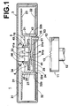
- FIG. 1 is a cross sectional view of a magnetic tape cartridge according to an embodiment of the invention, with the magnetic tape cartridge being in a non-operating state before chucking of a drive-side rotary driving member.
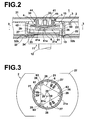
- FIG. 2 is a sectional view of the essential part of the magnetic tape cartridge in FIG. 1, with the magnetic tape cartridge being in an operating state after chucking.
- FIG. 3 is a plan view in section taken along line 3-3 of FIG. 2.
- FIGS. 4A is a bottom view of a reel of the magnetic tape cartridge with a reel gear being partially removed
- FIG. 4B is a bottom view of a metal plate.
- FIG. 5 is an enlarged cross-sectional view of the reel taken along line 5-5 in FIG. 4A.
- a magnetic tape cartridge 1 has a cartridge case 3 constituted by an upper case 31 and a lower case 32 that has an opening 32a at a central portion thereof and is fastened to the upper case 31 by screws or the like.
- a single reel 2 around which a magnetic tape (not shown) is wound is rotatably housed within the cartridge case 3, and a reel locking mechanism 10 for blocking rotation of the reel by locking the reel 2 when the magnetic tape cartridge is in a non-operating state is disposed within a center hole of the reel 2.
- the reel 2 comprises a reel hub 21 which is shaped in the form of a tubular member closed at its one end and around which the magnetic tape is wound; and lower and upper flanges 22 and 23 respectively extending radially outward from the outer peripheries of the upper and lower ends of the reel hub 21.
- the reel hub 21 and the lower flange 22 are integrally formed of a synthetic resin material.
- the upper flange 23, which is also formed of a synthetic resin material, is fixed to the reel hub 21 by ultrasonic welding, for example, while the upper flange 23 is fitted to a top.end of the reel hub 21.
- the center side lower portion of the reel hub is closed by a bottom wall 21a, and a crown gear type reel gear 24, which is meshable with a driving gear 13 of a drive-side rotary driving member 11, is provided in an annular form at an outer peripheral portion of a lower surface of the bottom wall 21a of the reel hub 21.
- a metal plate 25 shaped as shown in FIG. 4B is attached to the lower surface of the bottom wall 21a of the reel hub 21 by insert molding. In the outer peripheral edge of the metal plate 25, three cutouts 25a are formed such that the cutouts 25a do not overlap three through holes 26 formed in a pawl portion of the reel gear 24.
- the metal plate 25 is provided because the metal plate 25 is magnetically attracted to the drive-side rotary driving member 11, thus maintaining the meshed state between the reel gear 24 and the driving gear 13.
- the metal plate 25 has an outer diameter that is substantially equal to the outer diameter of the pawl portion of the reel gear 24.
- the outer periphery of the metal plate 25 is positioned under the inner facing surface of the reel gear such that the entire inner facing surface of the reel gear 24 is covered by the outer periphery of the reel gear 24.
- the outer peripheral edge of the metal plate 25 reaches the radially outermost end of the pawl portion of the reel gear 24.
- the reel gear 24 and the metal plate 25 are arranged so as to be exposed through the opening 32a in the bottom surface of the cartridge case 3.
- the peripheral edge portion around the opening 32a is raised in an annular form, and the upper surface of the raised portion defines a supporting surface 32b for supporting the lower surface of the lower flange 22 of the reel 2 when the magnetic tape cartridge is in a non-operating state.
- the reel 2 is urged downward by an urging member (coil spring) 5 provided in the reel locking mechanism 10 described later, thereby being in abutment with the supporting surface 32b.
- the drive-side rotary driving member 11 includes an annular driving gear 13 and a magnet (not shown), both of which are disposed on the upper surface of a disk portion 15 fixed to the upper end of a rotating shaft 12.
- a chucking operation of the aforementioned rotary driving member 11 is effected by lowering toward the rotating shaft 12 a magnetic tape cartridge 1 loaded in a drive-side bucket (not shown), meshing the driving gear 13 with the reel gear 24, and maintaining the meshed state therebetween due to magnetic attraction of the magnet attracting the reel plate 25.
- the reel locking mechanism 10 comprises: a locking member 4 that is movable in an axial direction of the reel 2 between a locked position and a release position; an urging member (coil spring) 5 for urging the locking member in the direction toward the locked position thereof; and a releasing member (release pad) 6 for moving the locking member 4 in the direction toward the release position thereof.
- Three through holes 26 which extend vertically through the pawl portion of the reel gear, are circumferentially disposed at equidistant intervals from one another.
- a lock tooth 29 is provided at each extremity of the interlocking protrusions 27.
- the locking member 4 is formed of a synthetic resin material and provided with a disk portion 41.
- the disk portion 41 is placed within the reel hub 21 facing the bottom wall 21a of the reel hub 21.
- Lock teeth 42 which are meshable with the lock teeth 29 of the interlocking protrusions 27, are arranged annularly at an outer peripheral portion of a lower surface of the disk portion 41.
- a spherical sliding portion 41a is defined at the central portion of the lower surface of the disk portion 41 so as to project therefrom. Under the urging force of the urging member 5, the sliding portion 41a is brought into abutment with a sliding portion 61a which is defined at the central portion of the upper surface of the body portion 61 of a releasing member 6 (described later).
- Each of the lock teeth 42 and 29 is formed in a conical shape so that the tooth height is greater towards the outer periphery of disk portion 41. Thus the radially outer side of the tooth is first brought into mesh with the radially outer side of the corresponding tooth.
- An upward extending projection 44 is disposed on the upper surface of the disk portion 41 of the locking member 4.
- a crucial interlocking groove 45 which extend vertically, is formed in the projection 44.
- a supporting portion 33 (a protrusion for blocking rotation) to be inserted into the interlocking groove 45 is provided upright on the inner surface of the upper case 31 of the cartridge case 3. Meshing the interlocking groove 45 with the supporting portion 33 enables the locking member 4 to move vertically with the rotation thereof being blocked.
- a biasing member 5 constituted by a coil spring is positioned in a compressed state between the upper surface of the disk portion 41 at a region disposed radially outward from the projection 44 of the locking member 4 and a spring bearing 34 provided radially outward of the supporting portion 33 of the upper case 31, whereby the lock teeth 42 of the locking member 4 are urged in a direction of meshing with the locking teeth 29 of the reel 2.
- the releasing member 6 is interposed between the locking member 4 and the bottom surface 21a of the reel hub 21 in a vertically movable manner, and downward extending cylindrical legs 63 are respectively arranged on the lower surface of an approximately triangular body 61 in the vicinity of the apexes thereof.
- Each leg 63 is movably inserted through each through hole 26 formed in the bottom surface 21a of the reel 2, and the tip of the leg 63 is positioned to be opposed to the pawl portion of the reel gear 24 disposed on the lower surface of the reel 2.
- the aforementioned interlocking protrusions are arranged radially outward of the body portion 61 and between the adjacent legs 63.
- the leg 63 may be formed in a prismatic shape or an elliptically cylindrical shape.
- the tip of the leg 63 protrudes from the lower surface of the reel gear 24.
- the releasing member 6 is pressed upward and pushed up over a predetermined stroke amount (see FIG 2).
- the reel 2 is also pushed up slightly by the driving gear 13 and separated from the lower case 32. Since the legs 63 are fitted within the through holes 26, the releasing member 6 rotates as one with the reel 2.
- the rotation of the reel 2 is thus blocked when the magnetic tape cartridge is in a non-operating state, and accordingly a locked state where drawing of the magnetic reel is blocked is obtained.
- a metal plate 25 which has a larger diameter than that of a conventional metal plate 25' shown in FIG. 6B is used, and the outer periphery of the metal plate 25 is positioned under the inner facing surface of the reel gear 24, and accordingly the periphery of the metal plate 25 comes close to the rim of the reel hub 21. Accordingly, as is apparent from FIG. 5, the thickness of a portion where the reel gear 24 is formed becomes smaller than that of the conventional products, and therefore a "sink mark" becomes less likely to occur during molding. Further, an effect that a stiff metal plate 25 suppresses deformation of the reel hub when tape is wound can also be expected. In addition, due to the increased mass of the metal plate 25, the meshed state between the reel gear 24 and the driving gear during chucking can be maintained more reliably.
- the metal plate 25 has the outer diameter that is substantially equal to the outer diameter of the pawl portion of the reel gear 24, and the outer periphery of the metal plate 25 is positioned under the inner facing surface of the reel gear such that the entire inner facing surface of the reel gear 24 is covered by the outer periphery of the reel gear 24.
- the object of the present invention is also achieved when the outer periphery of the metal plate is positioned under the inner facing surface of the reel gear 24 in a manner such that the outer peripheral edge of the metal plate 25 reaches at least the middle of a radial width of a pawl portion of the reel gear 24.
Landscapes
- Winding Of Webs (AREA)
- Storage Of Web-Like Or Filamentary Materials (AREA)
- Unwinding Webs (AREA)
Abstract
Description
wherein the metal plate is disposed on the bottom wall of the reel hub in a manner such that an outer periphery of the metal plate is positioned under the inner facing surface of the reel gear.
FIG. 1 is a cross sectional view of a magnetic tape cartridge according to an embodiment of the invention, with the magnetic tape cartridge being in a non-operating state before chucking of a drive-side rotary driving member. FIG. 2 is a sectional view of the essential part of the magnetic tape cartridge in FIG. 1, with the magnetic tape cartridge being in an operating state after chucking. FIG. 3 is a plan view in section taken along line 3-3 of FIG. 2. FIGS. 4A is a bottom view of a reel of the magnetic tape cartridge with a reel gear being partially removed, and FIG. 4B is a bottom view of a metal plate. FIG. 5 is an enlarged cross-sectional view of the reel taken along line 5-5 in FIG. 4A.
Claims (4)
- A magnetic tape cartridge (1) comprising:characterized in that the metal plate (25) is disposed on the bottom wall of the reel hub (21) in a manner such that an outer periphery of the metal plate (25) is positioned under the inner facing surface of the reel gear (24).a cartridge case (3), anda single reel (2) which is rotatably housed in the cartridge case (3), the single reel (2) having:(a) a reel hub (21) around which a magnetic tape is wound and a lower part of which is closed by a bottom wall,(b) upper and lower flanges respectively extending radially outward from the outer peripheries of the upper and lower ends of the reel hub (21),(c) a reel gear (24) provided in an annular form at an outer peripheral portion of a lower surface of the bottom wall of the reel hub (21) so as to be meshable with a driving gear of a drive-side rotary driving member provided in a drive device; and(d) a metal plate (25) which is to be magnetically attracted by the drive-side rotary driving member,
- A magnetic tape cartridge (1) according to claim 1, characterized in that the outer periphery of the metal plate (25) is positioned under the inner facing surface of the reel gear (24) in a manner such that the outer peripheral edge of the metal plate (25) reaches at least a middle of a radial width of a pawl portion of the reel gear (24).
- A magnetic tape cartridge (1) according to claim 1, characterized in that the outer periphery of the metal plate (25) is positioned under the inner facing surface of the reel gear (24) in a manner such that the outer peripheral edge of the metal plate (25) reaches a radially outermost end of a radial width of a pawl portion of the reel gear (24).
- A magnetic tape cartridge (1) according to one of claims 1 to 3, further comprising:characterized in that:a locking member (4) that is movable in an axial direction of the reel (2) between a locked position for blocking rotation of the reel and a release position for releasing a locked state of the reel 2; anda releasing member (6) for moving the locking member (4) in the direction toward the release position in association with meshing between a driving gear of a drive-side rotary driving member and the reel gear (24),the locking member (4) and the releasing member (6) are provided within the reel hub (21),the releasing member (6) includes a plurality of legs which respectively project outward through a plurality of through holes formed in the pawl portion of the reel gear (24) when the driving gear and the reel gear (24) are not meshed with each other, and are respectively pushed back into the plurality of through holes in association with meshing between the reel gear (24) and the driving gear, andcutouts are formed in the outer peripheral edge of the metal plate (25) such that the cutouts do not overlap the through holes formed in the pawl portion of the reel gear (24).
Applications Claiming Priority (2)
| Application Number | Priority Date | Filing Date | Title |
|---|---|---|---|
| JP2004061477 | 2004-03-05 | ||
| JP2004061477A JP2005251314A (en) | 2004-03-05 | 2004-03-05 | Magnetic tape cartridge |
Publications (3)
| Publication Number | Publication Date |
|---|---|
| EP1571669A2 true EP1571669A2 (en) | 2005-09-07 |
| EP1571669A3 EP1571669A3 (en) | 2007-08-29 |
| EP1571669B1 EP1571669B1 (en) | 2009-02-11 |
Family
ID=34747682
Family Applications (1)
| Application Number | Title | Priority Date | Filing Date |
|---|---|---|---|
| EP05004821A Expired - Lifetime EP1571669B1 (en) | 2004-03-05 | 2005-03-04 | Magnetic tape cartridge |
Country Status (4)
| Country | Link |
|---|---|
| US (1) | US7287716B2 (en) |
| EP (1) | EP1571669B1 (en) |
| JP (1) | JP2005251314A (en) |
| DE (1) | DE602005012639D1 (en) |
Families Citing this family (6)
| Publication number | Priority date | Publication date | Assignee | Title |
|---|---|---|---|---|
| JP4805232B2 (en) * | 2007-09-05 | 2011-11-02 | 富士フイルム株式会社 | reel |
| JP5377139B2 (en) * | 2008-07-28 | 2013-12-25 | 富士フイルム株式会社 | Reel and recording tape cartridge |
| US8123158B2 (en) * | 2008-07-28 | 2012-02-28 | Fujifilm Corporation | Reel and recording tape cartridge |
| JP4964343B1 (en) * | 2011-05-30 | 2012-06-27 | 富士フイルム株式会社 | Recording tape cartridge |
| JP6392083B2 (en) * | 2014-11-04 | 2018-09-19 | 富士フイルム株式会社 | Tape cartridge |
| US12347457B2 (en) * | 2021-03-31 | 2025-07-01 | Sony Group Corporation | Cartridge including magnetic tape including magnetic layer including protrusions on surface thereof |
Family Cites Families (7)
| Publication number | Priority date | Publication date | Assignee | Title |
|---|---|---|---|---|
| JP4094131B2 (en) * | 1998-07-31 | 2008-06-04 | 富士フイルム株式会社 | Magnetic tape cartridge reel |
| JP4108845B2 (en) * | 1998-11-12 | 2008-06-25 | 富士フイルム株式会社 | Magnetic tape cartridge reel molding method |
| JP2002093108A (en) * | 2000-09-14 | 2002-03-29 | Tdk Corp | Tape cartridge |
| US6700742B2 (en) * | 2001-01-18 | 2004-03-02 | Fuji Photo Film Co., Ltd. | Magnetic tape cartridge |
| JP2003085930A (en) * | 2001-05-29 | 2003-03-20 | Fuji Photo Film Co Ltd | Magnetic tape cartridge |
| JP2003091963A (en) | 2001-06-28 | 2003-03-28 | Fuji Photo Film Co Ltd | Recording tape cartridge |
| JP2003173654A (en) * | 2001-12-03 | 2003-06-20 | Tdk Corp | Tape cartridge |
-
2004
- 2004-03-05 JP JP2004061477A patent/JP2005251314A/en not_active Withdrawn
-
2005
- 2005-03-04 EP EP05004821A patent/EP1571669B1/en not_active Expired - Lifetime
- 2005-03-04 US US11/071,205 patent/US7287716B2/en not_active Expired - Fee Related
- 2005-03-04 DE DE602005012639T patent/DE602005012639D1/en not_active Expired - Lifetime
Also Published As
| Publication number | Publication date |
|---|---|
| JP2005251314A (en) | 2005-09-15 |
| US20050230513A1 (en) | 2005-10-20 |
| EP1571669B1 (en) | 2009-02-11 |
| DE602005012639D1 (en) | 2009-03-26 |
| EP1571669A3 (en) | 2007-08-29 |
| US7287716B2 (en) | 2007-10-30 |
Similar Documents
| Publication | Publication Date | Title |
|---|---|---|
| JP2002343058A (en) | Magnetic tape cartridge | |
| US7600710B2 (en) | Reel | |
| EP1571669B1 (en) | Magnetic tape cartridge | |
| EP1492112B1 (en) | Magnetic tape cartridge | |
| JP5634716B2 (en) | Reel and recording tape cartridge | |
| JP2000511682A (en) | Cassette having at least one axially movable reel and blocking means for preventing axial movement of the reel | |
| US7350732B2 (en) | Cartridge case and information recording medium | |
| US6886765B2 (en) | Single-reel magnetic tape cartridge | |
| US20070290095A1 (en) | Reel and manufacturing method thereof | |
| JP2005339753A (en) | Cartridge case and information recording medium | |
| JP4532041B2 (en) | Magnetic tape cartridge | |
| US7066421B2 (en) | Recording tape cartridge | |
| JP2001202744A (en) | Magnetic tape cartridge | |
| US6700742B2 (en) | Magnetic tape cartridge | |
| JP2002083481A (en) | Magnetic tape cartridge | |
| JP4542113B2 (en) | Magnetic tape cartridge | |
| JP2002352551A (en) | Magnetic tape cartridge | |
| US20070290089A1 (en) | Reel and reel manufacturing method | |
| US7364107B2 (en) | Tape cartridge | |
| JP6598751B2 (en) | Recording tape cartridge | |
| JP2005259226A (en) | Magnetic tape cartridge | |
| JP5127958B2 (en) | reel | |
| JP2002190177A (en) | Single reel type tape cartridge | |
| JPH0516988A (en) | Tape cassette case | |
| JP2007328835A (en) | Recording tape cartridge |
Legal Events
| Date | Code | Title | Description |
|---|---|---|---|
| PUAI | Public reference made under article 153(3) epc to a published international application that has entered the european phase |
Free format text: ORIGINAL CODE: 0009012 |
|
| AK | Designated contracting states |
Kind code of ref document: A2 Designated state(s): AT BE BG CH CY CZ DE DK EE ES FI FR GB GR HU IE IS IT LI LT LU MC NL PL PT RO SE SI SK TR |
|
| AX | Request for extension of the european patent |
Extension state: AL BA HR LV MK YU |
|
| RAP1 | Party data changed (applicant data changed or rights of an application transferred) |
Owner name: FUJIFILM CORPORATION |
|
| PUAL | Search report despatched |
Free format text: ORIGINAL CODE: 0009013 |
|
| AK | Designated contracting states |
Kind code of ref document: A3 Designated state(s): AT BE BG CH CY CZ DE DK EE ES FI FR GB GR HU IE IS IT LI LT LU MC NL PL PT RO SE SI SK TR |
|
| AX | Request for extension of the european patent |
Extension state: AL BA HR LV MK YU |
|
| 17P | Request for examination filed |
Effective date: 20071106 |
|
| AKX | Designation fees paid |
Designated state(s): DE FR GB |
|
| GRAP | Despatch of communication of intention to grant a patent |
Free format text: ORIGINAL CODE: EPIDOSNIGR1 |
|
| GRAS | Grant fee paid |
Free format text: ORIGINAL CODE: EPIDOSNIGR3 |
|
| GRAA | (expected) grant |
Free format text: ORIGINAL CODE: 0009210 |
|
| AK | Designated contracting states |
Kind code of ref document: B1 Designated state(s): DE FR GB |
|
| REG | Reference to a national code |
Ref country code: GB Ref legal event code: FG4D |
|
| REF | Corresponds to: |
Ref document number: 602005012639 Country of ref document: DE Date of ref document: 20090326 Kind code of ref document: P |
|
| PLBE | No opposition filed within time limit |
Free format text: ORIGINAL CODE: 0009261 |
|
| STAA | Information on the status of an ep patent application or granted ep patent |
Free format text: STATUS: NO OPPOSITION FILED WITHIN TIME LIMIT |
|
| 26N | No opposition filed |
Effective date: 20091112 |
|
| PGFP | Annual fee paid to national office [announced via postgrant information from national office to epo] |
Ref country code: DE Payment date: 20130227 Year of fee payment: 9 Ref country code: GB Payment date: 20130228 Year of fee payment: 9 Ref country code: FR Payment date: 20130325 Year of fee payment: 9 |
|
| REG | Reference to a national code |
Ref country code: DE Ref legal event code: R119 Ref document number: 602005012639 Country of ref document: DE |
|
| GBPC | Gb: european patent ceased through non-payment of renewal fee |
Effective date: 20140304 |
|
| REG | Reference to a national code |
Ref country code: FR Ref legal event code: ST Effective date: 20141128 |
|
| REG | Reference to a national code |
Ref country code: DE Ref legal event code: R119 Ref document number: 602005012639 Country of ref document: DE Effective date: 20141001 |
|
| PG25 | Lapsed in a contracting state [announced via postgrant information from national office to epo] |
Ref country code: GB Free format text: LAPSE BECAUSE OF NON-PAYMENT OF DUE FEES Effective date: 20140304 Ref country code: DE Free format text: LAPSE BECAUSE OF NON-PAYMENT OF DUE FEES Effective date: 20141001 Ref country code: FR Free format text: LAPSE BECAUSE OF NON-PAYMENT OF DUE FEES Effective date: 20140331 |