EP1571534A2 - Electronic apparatus having cooling system, radiator thereof, and method for manufacturing thereof - Google Patents
Electronic apparatus having cooling system, radiator thereof, and method for manufacturing thereof Download PDFInfo
- Publication number
- EP1571534A2 EP1571534A2 EP04005453A EP04005453A EP1571534A2 EP 1571534 A2 EP1571534 A2 EP 1571534A2 EP 04005453 A EP04005453 A EP 04005453A EP 04005453 A EP04005453 A EP 04005453A EP 1571534 A2 EP1571534 A2 EP 1571534A2
- Authority
- EP
- European Patent Office
- Prior art keywords
- radiator
- metal thin
- plate
- plural number
- thin tubes
- Prior art date
- Legal status (The legal status is an assumption and is not a legal conclusion. Google has not performed a legal analysis and makes no representation as to the accuracy of the status listed.)
- Withdrawn
Links
Images





Classifications
-
- B—PERFORMING OPERATIONS; TRANSPORTING
- B24—GRINDING; POLISHING
- B24B—MACHINES, DEVICES, OR PROCESSES FOR GRINDING OR POLISHING; DRESSING OR CONDITIONING OF ABRADING SURFACES; FEEDING OF GRINDING, POLISHING, OR LAPPING AGENTS
- B24B27/00—Other grinding machines or devices
- B24B27/06—Grinders for cutting-off
-
- F—MECHANICAL ENGINEERING; LIGHTING; HEATING; WEAPONS; BLASTING
- F28—HEAT EXCHANGE IN GENERAL
- F28F—DETAILS OF HEAT-EXCHANGE AND HEAT-TRANSFER APPARATUS, OF GENERAL APPLICATION
- F28F9/00—Casings; Header boxes; Auxiliary supports for elements; Auxiliary members within casings
- F28F9/02—Header boxes; End plates
- F28F9/04—Arrangements for sealing elements into header boxes or end plates
- F28F9/16—Arrangements for sealing elements into header boxes or end plates by permanent joints, e.g. by rolling
- F28F9/18—Arrangements for sealing elements into header boxes or end plates by permanent joints, e.g. by rolling by welding
- F28F9/182—Arrangements for sealing elements into header boxes or end plates by permanent joints, e.g. by rolling by welding the heat-exchange conduits having ends with a particular shape, e.g. deformed; the heat-exchange conduits or end plates having supplementary joining means, e.g. abutments
-
- B—PERFORMING OPERATIONS; TRANSPORTING
- B23—MACHINE TOOLS; METAL-WORKING NOT OTHERWISE PROVIDED FOR
- B23K—SOLDERING OR UNSOLDERING; WELDING; CLADDING OR PLATING BY SOLDERING OR WELDING; CUTTING BY APPLYING HEAT LOCALLY, e.g. FLAME CUTTING; WORKING BY LASER BEAM
- B23K31/00—Processes relevant to this subclass, specially adapted for particular articles or purposes, but not covered by any single one of main groups B23K1/00 - B23K28/00
- B23K31/02—Processes relevant to this subclass, specially adapted for particular articles or purposes, but not covered by any single one of main groups B23K1/00 - B23K28/00 relating to soldering or welding
-
- B—PERFORMING OPERATIONS; TRANSPORTING
- B24—GRINDING; POLISHING
- B24B—MACHINES, DEVICES, OR PROCESSES FOR GRINDING OR POLISHING; DRESSING OR CONDITIONING OF ABRADING SURFACES; FEEDING OF GRINDING, POLISHING, OR LAPPING AGENTS
- B24B23/00—Portable grinding machines, e.g. hand-guided; Accessories therefor
- B24B23/08—Portable grinding machines designed for fastening on workpieces or other parts of particular section, e.g. for grinding commutators
-
- B—PERFORMING OPERATIONS; TRANSPORTING
- B24—GRINDING; POLISHING
- B24B—MACHINES, DEVICES, OR PROCESSES FOR GRINDING OR POLISHING; DRESSING OR CONDITIONING OF ABRADING SURFACES; FEEDING OF GRINDING, POLISHING, OR LAPPING AGENTS
- B24B27/00—Other grinding machines or devices
- B24B27/0007—Movable machines
-
- F—MECHANICAL ENGINEERING; LIGHTING; HEATING; WEAPONS; BLASTING
- F28—HEAT EXCHANGE IN GENERAL
- F28D—HEAT-EXCHANGE APPARATUS, NOT PROVIDED FOR IN ANOTHER SUBCLASS, IN WHICH THE HEAT-EXCHANGE MEDIA DO NOT COME INTO DIRECT CONTACT
- F28D1/00—Heat-exchange apparatus having stationary conduit assemblies for one heat-exchange medium only, the media being in contact with different sides of the conduit wall, in which the other heat-exchange medium is a large body of fluid, e.g. domestic or motor car radiators
- F28D1/02—Heat-exchange apparatus having stationary conduit assemblies for one heat-exchange medium only, the media being in contact with different sides of the conduit wall, in which the other heat-exchange medium is a large body of fluid, e.g. domestic or motor car radiators with heat-exchange conduits immersed in the body of fluid
- F28D1/04—Heat-exchange apparatus having stationary conduit assemblies for one heat-exchange medium only, the media being in contact with different sides of the conduit wall, in which the other heat-exchange medium is a large body of fluid, e.g. domestic or motor car radiators with heat-exchange conduits immersed in the body of fluid with tubular conduits
- F28D1/053—Heat-exchange apparatus having stationary conduit assemblies for one heat-exchange medium only, the media being in contact with different sides of the conduit wall, in which the other heat-exchange medium is a large body of fluid, e.g. domestic or motor car radiators with heat-exchange conduits immersed in the body of fluid with tubular conduits the conduits being straight
- F28D1/05316—Assemblies of conduits connected to common headers, e.g. core type radiators
- F28D1/05333—Assemblies of conduits connected to common headers, e.g. core type radiators with multiple rows of conduits or with multi-channel conduits
-
- G—PHYSICS
- G06—COMPUTING OR CALCULATING; COUNTING
- G06F—ELECTRIC DIGITAL DATA PROCESSING
- G06F1/00—Details not covered by groups G06F3/00 - G06F13/00 and G06F21/00
- G06F1/16—Constructional details or arrangements
- G06F1/20—Cooling means
-
- H—ELECTRICITY
- H05—ELECTRIC TECHNIQUES NOT OTHERWISE PROVIDED FOR
- H05K—PRINTED CIRCUITS; CASINGS OR CONSTRUCTIONAL DETAILS OF ELECTRIC APPARATUS; MANUFACTURE OF ASSEMBLAGES OF ELECTRICAL COMPONENTS
- H05K7/00—Constructional details common to different types of electric apparatus
- H05K7/20—Modifications to facilitate cooling, ventilating, or heating
- H05K7/20009—Modifications to facilitate cooling, ventilating, or heating using a gaseous coolant in electronic enclosures
-
- F—MECHANICAL ENGINEERING; LIGHTING; HEATING; WEAPONS; BLASTING
- F28—HEAT EXCHANGE IN GENERAL
- F28D—HEAT-EXCHANGE APPARATUS, NOT PROVIDED FOR IN ANOTHER SUBCLASS, IN WHICH THE HEAT-EXCHANGE MEDIA DO NOT COME INTO DIRECT CONTACT
- F28D21/00—Heat-exchange apparatus not covered by any of the groups F28D1/00 - F28D20/00
- F28D2021/0019—Other heat exchangers for particular applications; Heat exchange systems not otherwise provided for
- F28D2021/0028—Other heat exchangers for particular applications; Heat exchange systems not otherwise provided for for cooling heat generating elements, e.g. for cooling electronic components or electric devices
- F28D2021/0029—Heat sinks
-
- G—PHYSICS
- G06—COMPUTING OR CALCULATING; COUNTING
- G06F—ELECTRIC DIGITAL DATA PROCESSING
- G06F2200/00—Indexing scheme relating to G06F1/04 - G06F1/32
- G06F2200/20—Indexing scheme relating to G06F1/20
- G06F2200/201—Cooling arrangements using cooling fluid
Definitions
- the present invention relates to an electronic apparatus, such as, a personal computer, being so-called a desktop-type or a notebook-type, or a server, etc., and in particular, it relates to an electronic apparatus having a liquid cooling system therein, thereby being able to cool down a heat-generation element mounted within an inside thereof, such as, a semiconductor integrated circuit (IC), effectively with an aid of a liquid refrigerant or coolant, and further the structure of a radiator suitable thereto and a manufacturing method thereof.
- a heat-generation element mounted within an inside thereof, such as, a semiconductor integrated circuit (IC), effectively with an aid of a liquid refrigerant or coolant, and further the structure of a radiator suitable thereto and a manufacturing method thereof.
- cooling is necessary for the heat-generation element, such as, the semiconductor IC element, being mounted within an electronic apparatus, including a personal computer, of so-called the desktop-type or the notebook-type, as well as, a server, etc., and in particular, the heat-generation element, such as, a CPU (Central Processing Unit), as a representative one thereof, for example.
- the cooling is achieved generally by using a heat transfer element, being so-called a heat sink that is formed with fins thereon, as well as a fan, being provided for sending a cooling air thereto.
- liquid cooling system of being high in the cooling efficiency thereof, which is used in the personal computer, of so-called the desktop-type or the notebook-type, and also the server, etc., as is known from the following patent documents, for example, in general, an element being so-called by a heat-receiving (or cooler) jacket is mounted on the surface of the heat-generating element, i.e., the CPU, directly, while conducting the liquid coolant within a flow passage formed within the heat-receiving jacket, so as to transmit or convey the heat generated from the CPU to the coolant flowing within the jacket mentioned above, thereby cooling down the heat-generating element with high efficiency.
- a heat-receiving (or cooler) jacket is mounted on the surface of the heat-generating element, i.e., the CPU, directly, while conducting the liquid coolant within a flow passage formed within the heat-receiving jacket, so as to transmit or convey the heat generated from the CPU to the coolant flowing within the jacket mentioned above, thereby cooling down the heat-generating element with high efficiency.
- a heat cycle is made up with the cooler jacket, as the heat-receiving portion thereof, and in more details thereof, it comprises a circulation pump for circulating the liquid coolant mentioned above within the cycle, so-called a radiator, being a heat-radiation portion for irradiating heat of the liquid coolant mentioned above into an outside, and further a coolant tank provided in a part of the cycle depending on the necessity thereof. And, those are connected through a tube made of a metal and/or an elastic material, such as rubber or the like, for example.
- a device is used in many cases, which is made up by winding around a metal thin tube, being made of copper, for example, in a zigzag manner, and further attached with fins for use of heat radiation on this metal thin tube, so as to improve the heat-radiation characteristic or capacity thereof. Or, alternately, it is made up with the metal thin tube, on which the fins are attached in advance, being wound around in the zigzag manner.
- the radiator of the conventional arts in particular, being made up with attaching the heat radiation fins on the metal thin tube zigzagged, which is actually used widely in the personal computer, being so-called the desktop type, and/or the server, etc., it has a drawback that the production process thereof is complex and takes much man-hour, therefore is relatively expensive on costs thereof. Also, with such the radiator of the conventional arts, due to the structure thereof, normally it must be manufactured into a predetermined shape, mainly in a plate-like or a cubic-like outer configuration of the radiator, as a whole.
- an object according to the present invention being accomplished by taking the drawbacks of the conventional arts mentioned above into the consideration thereof, it is to provide a radiator having the structure, so that it can be easily disposed even within the narrow space remaining within the housing, fitting thereof, and can be altered in the outer configuration thereof, as well as, can be manufactured cheaply, thereby to provide an electronic apparatus having the liquid cooling system therein, which can obtain the optimal cooling characteristics with using such the radiator, and further a manufacturing method of such the radiator.
- an electronic apparatus installing a semiconductor element within a housing thereof, which necessitates cooling for maintaining normal operation thereof, in a part of the housing, and having a cooling system, within said housing or in a part thereof, said cooling system, comprising: a cooling jacket, being thematically connected with said semiconductor element, for transmitting heat generated therein to a liquid coolant flowing within an inside thereof; a radiator for radiating the heat transmitted into the liquid coolant within said cooling jacket into an outside of the apparatus; and a circulation pump for circulating said liquid coolant in a loop, including said cooling jacket and said radiator therein, wherein: said radiator is built up, by disposing a plural number of metal thin tubes aligning in parallel to each other.
- said metal thin tube has a circular cross-section thereof, and said radiator comprises a ventilating means in a part thereof.
- a radiator for use in the electronic apparatus described in the claim 1 comprising: at least, a pair of header portions disposed opposing to each other, wherein each of said pair of the header portions comprises: a plate-like member being made from a member, which is plate-like and is processed into a predetermined shape, with forming a plural number of penetrating holes therein, into which said plural number of the metal thin tubes are inserted; and a cover portion being formed to have an outer configuration corresponding to that of said plate-like member, and having a recess portion on an interior side thereof, wherein: said plural number of the metal thin tubes are fixed into said penetrating holes formed at positions corresponding thereto on said plate-like member building up said pair of the header portions, each being inserted therein at a tip thereof, thereby disposing said plural number of the metal thin tubes in parallel with each other.
- said plate-like member and said cover portion are formed to have outer configurations, corresponding to each other, or each of said plural number of the metal tin tubes fixed to said penetrating holes, being inserted therein at the tips thereof, has flange portions in vicinity of both end portions thereof.
- a method for manufacturing the radiator comprising the following steps of: preparing said plate-like members and said cover portions for building up said pair of the header portions, and further said plural pieces of the metal thin tubes; disposing and fixing said plural number of the metal thin tubes on said plate-like members for building up said pair of the header portions, at positions corresponding thereto, respectively; and disposing and fixing said cover portions on said plate-like members after disposing and fixing said plural number of the metal thin tubes at the corresponding positions.
- said plural number of the penetrating holes are formed on a surface of said plate-like member through punching process, or that said plural number of the metal thin tubes are fixed on said plate-like members for building up said pair of the headers, at the corresponding positions, through brazing.
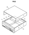
- Fig. 2 attached herewith shows an example of the entire structure of an electronic apparatus having a liquid cooling system therein, according to one embodiment of the present invention.
- a personal computer such as, of the desktop type, for example.
- the main part or portion of the desktop type personal computer comprises a housing 100, which is formed from a metal plate into a cubic shape thereof, for example, and on a front panel portion 101 thereof are provided various kinds of switches, including an electric power switch therein, and indicator lamps, etc. Also, within an inside thereof is disposed a driver device 102, for driving various kinds of external information recording medium, such as, a floppy disk, a CD, and a DVD, etc., so that it positions an opening thereof on the front panel portion 101. Also, a reference numeral 103 in the figure depicts a memory portion provided within the housing 100 mentioned above, comprising a hard disk device therein, for example. And also, a reference numeral 104 in the figure depicts a cover to be put on the housing 100 mentioned above.
- an electronic circuit portion 105 having a liquid cooling system according to the present invention
- a reference numeral 106 in the figure depicts an electric power source portion for supplying from a commercial electric power source, a desired electric power to each of the portions, including, the driver device 102, the memory portion 103, and the electronic circuit portion 105 mentioned above.
- Fig. 3 attached herewith is shown the electronic circuit portion 105 of the electronic apparatus, the brief structure of which was explained in the above; i.e., within the desktop type personal computer, in particular, mainly around a heat receiving jacket 50 for mounting thereon a heat-generation element, such as, a CPU, as a main or principle structure thereof.
- a heat-generation element such as, a CPU
- a chip 200 of the CPU being the heat-generation element, is mounted on the lower side surface of the heat-receiving jacket 50 mentioned above, being in contact with, directly, therefore it is not illustrated on the figure, herein.
- this electronic circuit portion 105 comprises the above-mentioned heat-receiving (or cooling) jacket 50 for mounting the CPU thereon, a radiator portion 60 for radiating heat generated from the CPU into an outside of the apparatus, a pump 70 for building up a cooling system, and further flow passages are formed by connecting tubes (conduits) 81, 82..., being made of a metal, or an elastic material, such as a rubber or the like, being covered with a metal film, etc.
- a liquid coolant for example, a water, or a mixture of water with a so-called anti-freezing solution, such as, propylene glycol, at a predetermined ratio thereof
- a liquid coolant for example, a water, or a mixture of water with a so-called anti-freezing solution, such as, propylene glycol, at a predetermined ratio thereof
- plate-like shaped fans 72, 72... in a plural number, such as, three (3) pieces, in the present example, directing into an outside of the apparatus, so as to blow an air onto a large number of metal thin pipes 61, 61...
- this heat-receiving (or cooling) jacket 50 is a plate-like member, being made of a metal having high heat conductivity, such as cupper or the like, and being formed with a cooling passage within an inside thereof, to conduct or communicate the liquid coolant into the passage thereof, thereby removing (moving) the heat generated from the CPU into the outside.
- Fig. 1 attached herewith shows the details of the structure of the radiator portion 60 mentioned above, in the form of an exploded view thereof.
- the radiator portion 60 is built up with a pair of headers 62 and 62, being disposed vertically or horizontally, for example, and also a large number of thin tubes 61, 61..., each being connected therebetween in parallel with one another.
- the thin tubes 61 are shown therein while being enlarged in the diameter thereof, for the purpose of explanation.
- the radiator according to the present example it is built up, by connecting about 400 pieces of the thin tubes 61, 61...
- each of the headers 62 having the sized of 100mm x 40mm, for example, in parallel with, respectively.
- each of the headers 62 mentioned above comprises one (1) piece of plate-like member 621, having a predetermined shape (in this example, a square shape), and also a cover member 623, which has an outer configuration corresponding to that of the plate-like member 621 (thus, being square in this example) and is formed with a recess or concaved portion 622 on an inner side thereof.
- a predetermined shape in this example, a square shape
- cover member 623 which has an outer configuration corresponding to that of the plate-like member 621 (thus, being square in this example) and is formed with a recess or concaved portion 622 on an inner side thereof.
- penetration holes 624 into which tip portion of the thin tubes 61 are inserted, in the number same to that of the tubes.
- each of those plate-likemembers 621 and the cover members 623 can be manufactured, easily from a metal plate having superior heat conductivity, such as, copper and/or aluminum, etc., being cut out into the predetermined shape through conducting the punching or drawing process thereon.
- a reference numeral 625 in the figure depicts tube-like members, each being attached onto the each cover member 623 mentioned above, thereby forming an inlet opening and an outlet opening for the liquid coolant, respectively.
- the each header 62 carries out the function as a reservoir tank for the liquid coolant, therefore the internal volume thereof is determined by an amount of liquid to be held within the cooling system (i.e., an amount of liquid being sufficient to compensate the amount of the liquid reduced accompanying with a long-time operation).
- the outlet opening of the radiator is located in a lower side thereof, thereby to be connected to the suction side of the pump, and then an air mixing within the liquid coolant is held within the upper-side header (i.e., the inlet-opening side of the radiator); therefore, it is possible to prevent the air from being sucked into the pump.
- Figs. 4(a) to 4(d) attached herewith show an example of the processes for inserting/fixing the metal thin tubes 61 into the penetrating holes 624 formed in the plate-like member 621, which builds up the header 62 mentioned above.
- the plate-like member 621 being made up in such the manner as was mentioned above and the metal thin tubes 61 are prepared (see Fig. 4(a)).
- the metal thin tubes 61 are inserted into the penetrating holes 621 formed on the plate-like member 621 prepared, in such the extent that each protrudes the tip thereof a little bit (see Fig. 4(b)).
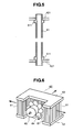
- a flange portion 611 in advance, in particular, in the vicinity of the tip portion of the metal thin tube 61 to be inserted into, as shown in Fig. 5 attached herewith, for example (i.e., in the present example, at an upper or lower end portion).
- the flange portion 611 in advances, in the vicinity of the tip portion of the metal thin tube 61, as is shown in the figure, it can bring about an easiness in bonding and inserting of the metal thin tubes 61 into the penetrating holes formed on the plate-like member 621, since the flange portion 611 carries out a role or function of positioning or stopping the metal thin tube 61 when it is inserted into the penetrating hole 624.
- Fig. 6 attached herewith shows an example of the radiator 60' suitable to be disposed within the narrow space, being narrow in the width but extending in the horizontal direction.
- the configuration of the pair of headers 62 and 62 mentioned above are shaped up to be "U"-like in the configuration, respectively, and a large number of the metal thin tubes 61 are disposed in parallel with between them, thereby building up the radiator 60'.
- a cooling fan 64 can be disposed within a recess portion 63 formed in a part thereof, and thereby enabling an effective utilization of the limited space at the maximum.
- an arrow shown in this figure indicates an airflow generated through the rotation of the cooling fan 64 mentioned above.
- Figs. 7(a) and 7(b) show an example of a radiator 60" suitable for to be disposed within a space remaining within the housing of the apparatus, being about cubic in the shape thereof and opening only in an upper portion thereof, as other example.
- each of the pair of headers 62 and 62, building up the radiator 62" mentioned above is square in the outer configuration thereof, and is formed with a circular opening in the central portion thereof, respectively, in this embodiment.
- radiators 60, 60' and 60" mentioned above are shown only in the disposition of being positioned, such that the pair of those headers 62 and 62 are located vertically, in the examples, however they should not be restricted thereto, but it is needless to mentioned about, in particular, that those can be disposed while directing the headers thereof horizontally, for example.
- the metal thin tubes 61 building up the heat-radiating portion thereof has no fin attached on the periphery thereof, in the structure, and further the outer periphery thereof is curved in the cylinder-like manner, therefore dusts hardly stick or adhere on the periphery thereof.
- the large number of metal thin tubes 61, building up such the radiators 60, 60' and 60", as was mentioned above, may be disposed or aligned on the surface of the header 62 (in more details, on the plate-like member 621 thereof), in a grid-like manner or a zigzag manner.
- those can be disposed at random in the position as far as they are in concert with each other between the positions where they are attached on the pair of headers 62 and 62. Accordingly, it is possible to achieve such a suitable pin arrangement, by taking the circulation of the cooling air by the fan into the consideration, and also the small or compact-sizing of the radiator, but without loosing the performance or capacity thereof.
- the radiator having such the structure it is possible to achieve the radiator having such the structure, that it can be also disposed in the narrow space remaining within the housing, easily, for example, in the personal computer of so-called the desktop type and the server, etc., and can be changed in the outer configuration thereof with easily, and manufactured cheaply, thereby to provide an electronic apparatus having the cooling system, in which the optimal cooling characteristic or capacity can be obtained with utilizing such the radiator, as well as the manufacturing method of such the radiator.
Landscapes
- Engineering & Computer Science (AREA)
- Physics & Mathematics (AREA)
- Mechanical Engineering (AREA)
- Thermal Sciences (AREA)
- General Engineering & Computer Science (AREA)
- Microelectronics & Electronic Packaging (AREA)
- Theoretical Computer Science (AREA)
- Human Computer Interaction (AREA)
- General Physics & Mathematics (AREA)
- Cooling Or The Like Of Electrical Apparatus (AREA)
- Cooling Or The Like Of Semiconductors Or Solid State Devices (AREA)
- Heat-Exchange Devices With Radiators And Conduit Assemblies (AREA)
Abstract
Description
Claims (8)
- An electronic apparatus, installing a semiconductor element within a housing thereof, which necessitates cooling for maintaining normal operation thereof, in a part of the housing, and having a cooling system, within said housing (100) or in a part thereof, said cooling system, comprising:a cooling jacket (50), being thematically connected with said semiconductor element, for transmitting heat generated therein to a liquid coolant flowing within an inside thereof;a radiator (60) for radiating the heat transmitted into the liquid coolant within said cooling jacket (50) into an outside of the apparatus; anda circulation pump (70) for circulating said liquid coolant in a loop, including said cooling jacket (50) and said radiator (60) therein, wherein:said radiator (60) is built up, by disposing a plural number of metal thin tubes (61) aligning in parallel to each other.
- Electronic apparatus, according to claim 1, characterized in that said metal thin tube (61) has a circular cross-section thereof, and said radiator (60) comprises a ventilating means in a part thereof.
- A radiator for an electronic apparatus, comprising:at least, a pair of header portions (62, 62) disposed opposing to each other, wherein each of said pair of the header portions (62, 62) comprises:a plate-like member (621) being made from a member, which is plate-like and is processed into a predetermined shape, with forming a plural number of penetrating holes (624) therein, into which said plural number of the metal thin tubes (61) are inserted; anda cover portion (623) being formed to have an outer configuration corresponding to that of said plate-like member (621), and having a recess portion on an interior side thereof, wherein:said plural number of the metal thin tubes (61) are fixed into said penetrating holes (624) formed at positions corresponding thereto on said plate-like member (621) building up said pair of the header portions (62), each being inserted therein at a tip thereof, thereby disposing said plural number of the metal thin tubes (61) in parallel with each other.
- Radiator according to claim 3, characterized in that said plate-like member (621) and said cover portion (623) are formed to have outer configurations, corresponding to each other.
- Radiator according to claim 3 or 4, characterized in that each of said plural number of the metal thin tubes (61) fixed to said penetrating holes (624), being inserted therein at the tips thereof, has flange portions (611) in vicinity of both end portions thereof.
- A method for manufacturing a radiator, comprising the following steps of:preparing plate-like members (621) and cover portions (623) for building up a pair of the header portions (62), and further plural pieces of metal thin tubes (61);disposing and fixing said plural number of the metal thin tubes (61) on said plate-like members (621) for building up said pair of the header portions (62), at positions corresponding thereto, respectively; anddisposing and fixing said cover portions (623) on said plate-like members (621) after disposing and fixing said plural number of metal thin tubes (61) at the corresponding positions.
- Method for manufacturing a radiator according to claim 6, characterized in that said plural number of the penetrating holes (624) are formed on a surface of said plate-like member (621) through a punching process.
- Method for manufacturing a radiator according to claim 6 or 7, characterized in that said plural number of the metal thin tubes (61) are fixed on said plate-like members (621) for building up said pair of the headers (62), at the corresponding positions, through brazing.
Applications Claiming Priority (2)
| Application Number | Priority Date | Filing Date | Title |
|---|---|---|---|
| JP2004038148A JP2005229032A (en) | 2004-02-16 | 2004-02-16 | Electronic device equipped with liquid cooling system, radiator thereof, and manufacturing method thereof |
| JP2004038148 | 2004-02-16 |
Publications (2)
| Publication Number | Publication Date |
|---|---|
| EP1571534A2 true EP1571534A2 (en) | 2005-09-07 |
| EP1571534A3 EP1571534A3 (en) | 2006-07-26 |
Family
ID=34747404
Family Applications (1)
| Application Number | Title | Priority Date | Filing Date |
|---|---|---|---|
| EP04005453A Withdrawn EP1571534A3 (en) | 2004-02-16 | 2004-03-08 | Electronic apparatus having cooling system, radiator thereof, and method for manufacturing thereof |
Country Status (5)
| Country | Link |
|---|---|
| US (1) | US20050178528A1 (en) |
| EP (1) | EP1571534A3 (en) |
| JP (1) | JP2005229032A (en) |
| KR (1) | KR20050081815A (en) |
| CN (1) | CN1658121A (en) |
Families Citing this family (21)
| Publication number | Priority date | Publication date | Assignee | Title |
|---|---|---|---|---|
| JP2005129812A (en) * | 2003-10-27 | 2005-05-19 | Hitachi Ltd | Liquid cooling system |
| TWM267509U (en) * | 2004-11-03 | 2005-06-11 | Forward Electronics Co Ltd | Improved structure of heat exchange radiator |
| CN100371854C (en) * | 2004-12-24 | 2008-02-27 | 富准精密工业(深圳)有限公司 | Liquid-cooled heat sink |
| TWM284949U (en) * | 2005-09-21 | 2006-01-01 | Yen Sun Technology Corp | Heat dissipating device for an electronic device |
| US7548421B2 (en) * | 2005-10-25 | 2009-06-16 | Hewlett-Packard Development Company, L.P. | Impingement cooling of components in an electronic system |
| JP4742965B2 (en) * | 2006-04-18 | 2011-08-10 | パナソニック株式会社 | Heat transfer device and liquid cooling system using it |
| KR100873843B1 (en) | 2007-02-27 | 2008-12-15 | 한국생산기술연구원 | Water-cooled chiller of semiconductor device |
| EP2172731A3 (en) * | 2008-10-03 | 2013-08-21 | Danfoss Drives A/S | A flow distributor assembly and a cooling unit with a flow distributor assembly |
| CN102056459A (en) * | 2009-10-30 | 2011-05-11 | 鸿富锦精密工业(深圳)有限公司 | Liquid-cooling heat radiating device |
| JP5953206B2 (en) * | 2011-11-11 | 2016-07-20 | 昭和電工株式会社 | Liquid cooling type cooling device and manufacturing method thereof |
| EP2661598B1 (en) * | 2012-02-21 | 2018-08-01 | Huawei Technologies Co., Ltd. | Cooling system and method for cooling a heat generating unit |
| CN104144592B (en) * | 2013-05-09 | 2016-12-07 | 鸿富锦精密工业(深圳)有限公司 | Cooling system and be provided with the Cabinet-type server of this cooling system |
| US20150330718A1 (en) * | 2013-08-28 | 2015-11-19 | Hamilton Sundstrand Corporation | Integrated blower diffuser-fin single phase heat exchanger |
| CN105202844B (en) * | 2015-10-20 | 2017-06-16 | 中国电子科技集团公司第四十四研究所 | High efficiency water cooling box |
| US20190212066A1 (en) * | 2018-01-11 | 2019-07-11 | Asia Vital Components Co., Ltd. | Water-cooling radiator assembly with internal horiziontal partition members and flow disturbing members |
| JP7247517B2 (en) * | 2018-10-24 | 2023-03-29 | 日本電産株式会社 | Cooling system |
| KR102880271B1 (en) * | 2020-03-18 | 2025-11-03 | 한온시스템 주식회사 | Heat exchanger |
| CN111556694B (en) * | 2020-04-30 | 2021-04-06 | 苏州市通准精密塑胶五金有限责任公司 | Radiating fin |
| CN112860042B (en) * | 2021-02-09 | 2025-02-07 | 华勤技术股份有限公司 | Liquid cooling device and electronic equipment |
| CN113370056A (en) * | 2021-05-31 | 2021-09-10 | 贵州航天电子科技有限公司 | Polishing method of radiator |
| CN113641226B (en) * | 2021-09-01 | 2024-10-15 | 中科可控信息产业有限公司 | Radiator assembling system and assembling method |
Family Cites Families (12)
| Publication number | Priority date | Publication date | Assignee | Title |
|---|---|---|---|---|
| US4377203A (en) * | 1980-05-20 | 1983-03-22 | Kabushiki Kaisha Komatsu Seisakusho | Radiator equipped with a centrifugal fan |
| US5285347A (en) * | 1990-07-02 | 1994-02-08 | Digital Equipment Corporation | Hybird cooling system for electronic components |
| JPH05264139A (en) * | 1992-03-18 | 1993-10-12 | Fujitsu Ltd | Refrigerant supplying system |
| US5275232A (en) * | 1993-03-15 | 1994-01-04 | Sandia National Laboratories | Dual manifold heat pipe evaporator |
| JPH07151488A (en) * | 1993-11-29 | 1995-06-16 | Sanden Corp | Heat exchanger and manufacture thereof |
| JP3216770B2 (en) * | 1995-03-20 | 2001-10-09 | カルソニックカンセイ株式会社 | Cooling device for electronic components |
| JPH09280755A (en) * | 1996-04-18 | 1997-10-31 | Sanden Corp | Tubular heat exchanger |
| US6019165A (en) * | 1998-05-18 | 2000-02-01 | Batchelder; John Samuel | Heat exchange apparatus |
| TW556328B (en) * | 2001-05-11 | 2003-10-01 | Denso Corp | Cooling device boiling and condensing refrigerant |
| US6666261B2 (en) * | 2001-06-15 | 2003-12-23 | Foxconn Precision Components Co., Ltd. | Liquid circulation cooler |
| US6600649B1 (en) * | 2002-05-24 | 2003-07-29 | Mei-Nan Tsai | Heat dissipating device |
| US6827131B1 (en) * | 2003-07-21 | 2004-12-07 | Neng Chao Chang | Apparatus of water-cooled heat sink |
-
2004
- 2004-02-16 JP JP2004038148A patent/JP2005229032A/en active Pending
- 2004-03-05 US US10/792,689 patent/US20050178528A1/en not_active Abandoned
- 2004-03-05 CN CN2004100077739A patent/CN1658121A/en active Pending
- 2004-03-05 KR KR1020040014825A patent/KR20050081815A/en not_active Ceased
- 2004-03-08 EP EP04005453A patent/EP1571534A3/en not_active Withdrawn
Also Published As
| Publication number | Publication date |
|---|---|
| EP1571534A3 (en) | 2006-07-26 |
| KR20050081815A (en) | 2005-08-19 |
| US20050178528A1 (en) | 2005-08-18 |
| JP2005229032A (en) | 2005-08-25 |
| CN1658121A (en) | 2005-08-24 |
Similar Documents
| Publication | Publication Date | Title |
|---|---|---|
| EP1571534A2 (en) | Electronic apparatus having cooling system, radiator thereof, and method for manufacturing thereof | |
| EP1564809A1 (en) | Liquid cooling system and electronic apparatus comprising that system | |
| US7516777B2 (en) | Cooling jacket | |
| JP3942248B2 (en) | Heat sink and information processing apparatus equipped with the same | |
| CN101370370B (en) | Heat radiation module | |
| EP1675451B1 (en) | Liquid cooling module | |
| US6639797B2 (en) | Computer having cooling device | |
| CN1455638A (en) | Electronic apparatus of display unit with heat radiator of radiation heating component | |
| US20060162901A1 (en) | Blower, cooling device including the blower, and electronic apparatus including the cooling device | |
| JP2002368467A (en) | Electronic device with built-in heating element and cooling device used for this electronic device | |
| JP2002182796A (en) | Display integrated computer | |
| EP1571533A2 (en) | Liquid cooling system, and electronic apparatus having the same therein | |
| WO2003043397A1 (en) | Electronic apparatus | |
| CN218630660U (en) | Server | |
| EP1708263A1 (en) | Cooling jacket | |
| JP2006234255A (en) | RADIATOR AND LIQUID COOLING SYSTEM HAVING THE RADIATOR | |
| CN1490695A (en) | Electronic device provided with circulation loop for liquid coolant and electrical signal cables | |
| JPH10107192A (en) | heatsink | |
| US20080011455A1 (en) | Composite heat-dissipating module | |
| JP5365555B2 (en) | Heat sink and information processing apparatus equipped with the same | |
| CN224218715U (en) | Liquid cooling heat dissipation module and electronic expansion device having the liquid cooling heat dissipation module | |
| CN219225909U (en) | Integrated liquid cooling system | |
| CN111594462B (en) | Heat sink and CPU with it | |
| JP2004087741A (en) | Cooling device provided with heat sink | |
| JP2008060310A (en) | COOLING DEVICE AND ELECTRONIC DEVICE HAVING THE SAME |
Legal Events
| Date | Code | Title | Description |
|---|---|---|---|
| PUAI | Public reference made under article 153(3) epc to a published international application that has entered the european phase |
Free format text: ORIGINAL CODE: 0009012 |
|
| AK | Designated contracting states |
Kind code of ref document: A2 Designated state(s): AT BE BG CH CY CZ DE DK EE ES FI FR GB GR HU IE IT LI LU MC NL PL PT RO SE SI SK TR |
|
| AX | Request for extension of the european patent |
Extension state: AL LT LV MK |
|
| PUAL | Search report despatched |
Free format text: ORIGINAL CODE: 0009013 |
|
| AK | Designated contracting states |
Kind code of ref document: A3 Designated state(s): AT BE BG CH CY CZ DE DK EE ES FI FR GB GR HU IE IT LI LU MC NL PL PT RO SE SI SK TR |
|
| AX | Request for extension of the european patent |
Extension state: AL LT LV MK |
|
| STAA | Information on the status of an ep patent application or granted ep patent |
Free format text: STATUS: THE APPLICATION IS DEEMED TO BE WITHDRAWN |
|
| AKX | Designation fees paid |
Designated state(s): DE |
|
| 18D | Application deemed to be withdrawn |
Effective date: 20070127 |