EP1571489A1 - Projection type image display unit - Google Patents
Projection type image display unit Download PDFInfo
- Publication number
- EP1571489A1 EP1571489A1 EP03778848A EP03778848A EP1571489A1 EP 1571489 A1 EP1571489 A1 EP 1571489A1 EP 03778848 A EP03778848 A EP 03778848A EP 03778848 A EP03778848 A EP 03778848A EP 1571489 A1 EP1571489 A1 EP 1571489A1
- Authority
- EP
- European Patent Office
- Prior art keywords
- ion wind
- wind generator
- video display
- temperature
- projection type
- Prior art date
- Legal status (The legal status is an assumption and is not a legal conclusion. Google has not performed a legal analysis and makes no representation as to the accuracy of the status listed.)
- Granted
Links
Images


Classifications
-
- H—ELECTRICITY
- H01—ELECTRIC ELEMENTS
- H01T—SPARK GAPS; OVERVOLTAGE ARRESTERS USING SPARK GAPS; SPARKING PLUGS; CORONA DEVICES; GENERATING IONS TO BE INTRODUCED INTO NON-ENCLOSED GASES
- H01T23/00—Apparatus for generating ions to be introduced into non-enclosed gases, e.g. into the atmosphere
-
- G—PHYSICS
- G03—PHOTOGRAPHY; CINEMATOGRAPHY; ANALOGOUS TECHNIQUES USING WAVES OTHER THAN OPTICAL WAVES; ELECTROGRAPHY; HOLOGRAPHY
- G03B—APPARATUS OR ARRANGEMENTS FOR TAKING PHOTOGRAPHS OR FOR PROJECTING OR VIEWING THEM; APPARATUS OR ARRANGEMENTS EMPLOYING ANALOGOUS TECHNIQUES USING WAVES OTHER THAN OPTICAL WAVES; ACCESSORIES THEREFOR
- G03B21/00—Projectors or projection-type viewers; Accessories therefor
- G03B21/14—Details
- G03B21/16—Cooling; Preventing overheating
-
- H—ELECTRICITY
- H04—ELECTRIC COMMUNICATION TECHNIQUE
- H04N—PICTORIAL COMMUNICATION, e.g. TELEVISION
- H04N9/00—Details of colour television systems
- H04N9/12—Picture reproducers
- H04N9/31—Projection devices for colour picture display, e.g. using electronic spatial light modulators [ESLM]
- H04N9/3141—Constructional details thereof
-
- H—ELECTRICITY
- H04—ELECTRIC COMMUNICATION TECHNIQUE
- H04N—PICTORIAL COMMUNICATION, e.g. TELEVISION
- H04N9/00—Details of colour television systems
- H04N9/12—Picture reproducers
- H04N9/31—Projection devices for colour picture display, e.g. using electronic spatial light modulators [ESLM]
- H04N9/3141—Constructional details thereof
- H04N9/3144—Cooling systems
-
- H—ELECTRICITY
- H04—ELECTRIC COMMUNICATION TECHNIQUE
- H04N—PICTORIAL COMMUNICATION, e.g. TELEVISION
- H04N5/00—Details of television systems
- H04N5/74—Projection arrangements for image reproduction, e.g. using eidophor
- H04N5/7416—Projection arrangements for image reproduction, e.g. using eidophor involving the use of a spatial light modulator, e.g. a light valve, controlled by a video signal
Definitions
- the present invention relates to a projection type video display such as a liquid crystal projector, and the like.
- a projection type video display is so configured that light emitted from a light source is modulated by a light valve such as a liquid crystal panel, and the like, and projected, so that it is necessary to comprise a high-luminance light source. Consequently, measures to prevent heat generated from the high-luminance light source itself and heat generated when light is absorbed in a light polarizer in the liquid crystal panel or various types of optical components are required.
- a projection type video display has a structure in which air is taken in and exhausted, and the heat is released from a casing by rotating a fan with a motor (see JP-A-2001-222065).
- a projection type video display is a projection type video display that modulates light emitted from a light source by a light valve and projects the modulated light, and comprises an ion wind generator for generating air flow by ionizing air and molecules in the air using an electrode on one side and drawing ions generated by the ionization by an electrode on the other side, and an ozone removal filter provided on a path of the air flow.
- the ion wind generator allows the air flow to be occurred by electrically moving an ionized air, and the like. As a result, different from blowing by the rotation of a fan, no rotation noise is produced, so that, when air is taken in or exhausted, an almost soundless state is made possible. Moreover, even if ozone is generated by the ionization, the ozone is removed by the ozone removal filter.
- An ozone removal filter may be provided on a path of the air flow warmed by drawing heat generated in the video display. Furthermore, the ozone removal filter may be provided in a position on a path of the air flow and in the vicinity of a light source. A reflector composing the light source transmits infrared light and the infrared light may be guided to the ozone removal filter. Such the configurations are useful in a case where the ozone removal filter is required to be heated to high temperature in some degree for sufficient demonstration of a removal capability.
- the ion wind generator may be so provided as to take air outside of the video display into the video display. Furthermore, in this configuration, if a mechanism in which dust is caught by the electrode on the other side of the ion wind generator is utilized, the ion wind generator becomes a dust removal device. When the ion wind generator is used as the dust removal device and used together with a fan, dust removal is possible without reducing a blowing capability of the fan. Moreover, the ozone is removed by the ozone removal filter.
- a projection type video display comprises a sensor for detecting temperature or ambient temperature of the ozone removal filter and a control means for turning on the ion wind generator when the temperature is equal to or higher than predetermined temperature and turning off the ion wind generator when the temperature is lower than the predetermined temperature.
- the ion wind generator is turned on or off when a predetermined time period has passed after the light source was turned on or off. Also in this configuration, it is possible to send an air after reaching the stage that the ozone removal capability of the ozone removal filter is fully demonstrated, the ventilation of the generated ozone outward the video display is reduced as much as possible.
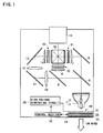
- Fig.1 is a diagram showing an optical system of a three-panel color liquid crystal projector.
- a light emitter 2 of a light source 1 is composed of an ultra-high pressure mercury lamp, a metal halide lamp, a xenon lamp, and the like, and light irradiated therefrom is emitted after being changed into parallel light by a parabolic reflector 3, for example.
- a first dichroic mirror 5 transmits light in a red wavelength band, while reflecting light in a cyan (green + blue) wavelength band.
- the light in the red wavelength band which passes through the first dichroic mirror 5 is reflected by a reflection mirror 6 so that its optical path is changed.
- the red light which is reflected by the reflection mirror 6 is optically modulated by passing through a transmission type liquid crystal light valve for red light 31 through a condenser lens 7.
- the light in the cyan wavelength band which is reflected by the first dichroic mirror 5 is guided to a second dichroic mirror 8.
- the second dichroic mirror 8 transmits light in a blue wavelength band, while reflecting light in a green wavelength band.
- the light in the green wavelength band which is reflected by the second dichroic mirror 8 is guided to a transmission type liquid crystal light valve for green light 32 through a condenser lens 9 to be optically modulated by passing through the liquid crystal light valve for green light 32.
- the light in the blue wavelength band which passes through the second dichroic mirror 8 is guided to a transmission type liquid crystal light valve for blue light 33 through reflection mirrors 11 and 13, relay lenses 10 and 12, and a condenser lens 14, to be optically modulated by passing through the liquid crystal light valve for blue light 33.
- Each of the above-described liquid crystal light valves 31, 32, and 33 comprises an incidence-side polarizer, a panel constructed by sealing a liquid crystal between a pair of glass plates (where a pixel electrode and an alignment film are formed), and a light exit side polarizer.
- Modulated light image light in respective colors
- the color image light is projected by a projection lens 16 and is displayed on a screen (not shown).
- An ion wind generator 20 is provided at the back of the light source 1. As shown also in Fig.2, the ion wind generator 20 negatively ionizes air and molecules by corona discharges using negative-side, a multiplicity of needle electrodes 21 and draws the negatively-ionized air and molecules to a ground-side mesh electrode 22 to produce air flow.
- a high-voltage generating circuit 26 receives voltage supply from a power supply (not shown) to generate a high voltage ranging from a few minus kilovolts to minus ten and several kilovolts and applies the high voltage to the electrodes 21.
- an air supply port of the ion wind generator 20 faces an exhaust port at a rear surface of a casing.
- the air flow generated by the ion wind generator 20 is exhausted outward from the projector, the ambient air heated to high temperature by the heat produced by the light source 1 is drawn and exhausted out of the projector on the air flow.
- An ozone decomposition catalyst filter 23 is provided in the exhaust port at the rear surface of the casing.
- the ozone decomposition catalyst filter 23 is constructed by additionally attaching a catalyst such as a manganese dioxide, a nickel oxide, and others, to a ventilation supporting body in a honey-comb shape.
- Ozone (O 3 ) is generated by corona discharges in the ion wind generator 20. The ozone is guided to the outside of the projector on air flow, and the ozone is decomposed by passing through the ozone decomposition catalyst filter 23 provided in the exhaust port.
- a certain level of temperature is needed for the ozone decomposition catalyst filter 23 to fully demonstrate an ozone decomposition capability.
- the ambient air heated to high temperature by the heat of the light source 1 is exhausted out of the projector on the air flow, and the heat of high-temperature air is applied to the ozone decomposition catalyst filter 23.
- temperature of the ozone decomposition catalyst filter 23 increases, and the ozone decomposition capability of the ozone decomposition catalyst filter 23 is increased.
- the temperature of the ozone decomposition catalyst filter 23 is increased also by the infrared rays emitted from the light source 1.
- the ozone decomposition capability is increased (An infrared rays reflecting mirror and the like, may be provided so as to positively guide the infrared rays emitted from the light source 1 to the ozone decomposition catalyst filter 23.).
- the temperature of the ozone decomposition catalyst filter 23 is equal to room temperature, so that it is impossible that the ozone decomposition capability is fully demonstrated. Therefore, such control as described below is performed.
- a temperature sensor 24 and a control section 25 are provided.
- the temperature sensor 24 detects the temperature of the ozone decomposition catalyst filter 23 or ambient temperature thereof.
- the result of detection (voltage value) is sent to the control section 25.
- the control section 25 issues an on-command to the high-voltage generating circuit 26 so as to activate the ion wind generator 20 when the detected temperature is equal to or higher than predetermined temperature, and on the other hand, issues an off-command to the high-voltage generating circuit 26 so as to stop the ion wind generator 20 when the detected temperature is lower than the predetermined temperature.
- the predetermined temperature varies depending on a catalyst which is used or on heat-resistance temperature of optical devices in the projector, the temperature may be set to around from 70 degrees centigrade to 90 degrees centigrade, for example.
- Fig.3 shows, in addition to an elapse of time period and a change in temperature in the projector, on and off timing of the light source 1 and the on and off timing of the ion wind generator 20.
- the temperature in the projector immediately after the light source 1 was turned on is equal to room temperature. Afterward, however, the temperature in the projector is increased by the heat generated by the light source 1 and also the temperature of the ozone decomposition catalyst filter 23 is increased.
- the ion wind generator 20 is turned on, so that the temperature in the projector is kept at a steady temperature by cooling with ion wind.
- the temperature in the projector is still high, accordingly the temperature of the ozone decomposition catalyst filter 23 is high. Therefore, an on-state of the ion wind generator 20 is maintained for a while, and when the detected temperature drops to less than the predetermined temperature, the ion wind generator is tuned off. Thus, the ion wind generator 20 is turned on and off depending on temperature detection. Accordingly, since it is possible to send an air after reaching the stage that the ozone removal capability of the ozone decomposition catalyst filter 23 is fully demonstrated, the ventilation of generated ozone out of the projector is reduced as much as possible.
- the high-temperature air surrounding the light source 1 is drawn using the ion wind generated by the ion wind generator 20, and guided to the outside of the projector.
- the ion wind generated by the ion wind generator 20 may be blown onto the light source 1.
- the ozone decomposition catalyst filter 23 is arranged in the close vicinity of a reflector 3 of the light source 1.
- the configuration in which the ion wind generator 20 is arranged in the vicinity of the light source 1 is shown.
- the ion wind generator may be arranged at another location where air is heated to high temperature (the location near a liquid crystal display panel, etc).
- the ion wind generator may be so constructed that the air flow is generated by ionization of air or molecules in the air.
- the ion wind generator different from the above-described specific structure may be used.
- the temperature sensor 24 measures the temperature or the ambient temperature of the ozone decomposition catalyst filter 23 and operates the ion wind generator 20.
- a measuring by a timer is performed, and when predetermined period passes, the ion wind generator 20 may be turned on, for example.
- the measuring by a timer is performed, and when the predetermined period passes, the ion wind generator 20 may be turned off. Also in such the configurations, it is possible to send the air after reaching the stage that the ozone removal capability of the ozone decomposition catalyst filter 23 is fully demonstrated, the ventilation of generated ozone out of the projector is reduced as much as possible.
- a fan 200 (hereinafter, referred to as a dust collection wind fan 200) with the ion wind generator provided in the projection type video display of an embodiment of the present invention will be described with referring to Figs.4 to 5.
- Fig.4 is a perspective view (partly transparent) showing the dust collection wind fan 200.
- the dust collection wind fan 200 comprises a dust collection portion (ion wind generator) and a wind fan portion (sirocco fan).
- the dust collection wind fan 200 is constructed by arranging needle electrodes 221, a first mesh electrode 222A and a second mesh electrode 222B, and an ozone decomposition catalyst filter 223 in a rectangular cylinder in the above-mentioned order in the direction of air flow.
- the dust collection wind fan 200 negatively ionizes air, dust, and the like, by corona discharges using a multiplicity of negative-side needle electrodes 221, and generates air flow by drawing the negatively-ionized air, dust, and the like, using ground-side first and second mesh electrodes 222A and 222B, in addition, catches dust using the mesh electrode 222B.
- the ozone decomposition catalyst filter 223 is constructed by attaching a catalyst such as a manganese dioxide, a nickel oxide, an activated carbon, and the like, to the inner surface of each hole in a honey-comb shape. Even if ozone (O 3 ) is generated by the corona discharges, the generated ozone is decomposed and removed before being guided to a sirocco fan 224 by passing through the ozone decomposition catalyst filter 223.
- the high-voltage generating circuit 26 receives voltage supply from a power supply (not shown) to generate a high voltage ranging from a few minus kilovolts to minus ten and several kilovolts and applies the high voltage to the electrodes 221.
- the sirocco fan 224 takes in and blows the air flow cleaned by the dust collection portion through a hood portion (elbow portion) 225.
- the sirocco fan 224 takes in air in the direction of axis of fan rotation, and exhausts the air in the direction perpendicular to the direction of axis of fan rotation.
- a diameter of a mesh aperture (in case of a round shape) or a length of one side (in case of a square shape) of the first mesh electrode 222A is set to several millimeters, for example.
- the diameter of a mesh aperture (in case of the round shape) or the length of one side (in case of the square shape) of the second mesh electrode 222B is set to a size approximately 10 times as large as that of a pixel of a liquid crystal display panel (10 ⁇ 20um), for example. Dust collection is mainly performed by the second mesh electrode 222B.
- the first mesh electrode 222A is fixedly arranged inside the rectangular cylinder.
- the second mesh electrode 222B and the ozone decomposition catalyst filter 223 are arranged removably from the rectangular cylinder.
- the dust collection wind fan 200 in the configuration of above-described Fig.4 is arranged on a lower side of an image light generating optical system as shown in Fig.5, for example.
- a duct 227 is provided in the air supply port of the sirocco fan 224.
- the tip of the duct 227 is divided into three and the respective apertures on the three tips are located on the lower side of the liquid crystal valves 31, 32, and 33, and wind is blown toward the light valves located on an upper side of the apertures.
- the mesh electrode in the above-described configuration it is possible to make a width of the aperture sufficiently larger than a size of the pixel of the liquid crystal panel, thereby a resistance is reduced.
- an air flow is generated by the dust collection portion (the ion wind generator) in a direction of air suction of the sirocco fan 224. These two effects reduce a resistance against a stream of air toward the sirocco fan 224, and prevent dust from entering.
- Ozone (O 3 ) is generated by the corona discharges in the dust collection portion, and the ozone is guided to the liquid crystal light valves 31, 32, and 33 on the air flow. However, the ozone is decomposed by passing through the ozone decomposition catalyst filter 223.
- Embodiment 2 same as in Embodiment 1, it is preferable to perform the on and off control of the ion wind generator (dust collection portion) or the on and off control of the whole dust collection wind fan 200.
- the ozone decomposition catalyst filter 223 gets fresh air, so that the increase in temperature is lower than Embodiment 1. However, the temperature in the projector is increased by the heat emitted by the light source, etc. Accordingly, the temperature of the ozone decomposition catalyst filter 223 is also increased.
- the temperature increase in the ozone decomposition catalyst filter 223 is waited, and after the temperature of the ozone decomposition catalyst filter 223 increased, the ion wind generator (dust collection port) or the whole dust collection wind fan 200 may be turned on.
- the ozone decomposition catalyst filter 223 may be placed at the exhaust side where air is exhausted after the heat of the liquid crystal valves 31, 32, and 33 is drawn by cooling air.
- the video generating optical system using three transmission-type liquid crystal display panels is shown, however the present invention is not limited to the same.
- the present invention is adaptable to a case where another image generating optical system is used.
Landscapes
- Engineering & Computer Science (AREA)
- Multimedia (AREA)
- Signal Processing (AREA)
- Physics & Mathematics (AREA)
- General Physics & Mathematics (AREA)
- Projection Apparatus (AREA)
- Transforming Electric Information Into Light Information (AREA)
Abstract
High-temperature air surrounding the light source (1) is drawn by the air flow and exhausted from a exhaust port at a rear side of a casing. An ozone decomposition catalyst filter 23 is provided in the exhaust port. Ozone (O3) is generated by the corona discharges in the ion wind generator (20). However, the ozone is decomposed by passing through the ozone decomposition catalyst filter 23 provided at the exhaust port.
Description
Claims (8)
- A projection type video display that modulates light emitted from a light source by a light valve and projects the modulated light, comprising:an ion wind generator for generating air flow by ionizing air and molecules in the air using an electrode on one side and drawing ions generated by the ionization by an electrode on the other side; andan ozone removal filter provided on a path of the air flow.
- A projection type video display according to claim 1, wherein the ozone removal filter is provided on a path of the air flow warmed by drawing heat generated in the video display.
- A projection type video display according to claim 1, wherein the ozone removal filter is provided in a position on a path of the air flow and in the vicinity of the light source.
- A projection type video display according to claim 3, wherein a reflector composing the light source transmits infrared light and the infrared light is guided to the ozone removal filter.
- A projection type video display according to claim 1, wherein the ion wind generator is so provided as to take air outside the video display into the video display.
- A projection type video display according to claim5, wherein dust is caught by the electrode on the other side of the ion wind generator.
- A projection type video display according to any one of claims 1 to 6, comprising:a sensor for detecting temperature or ambient temperature of the ozone removal filter; anda control means for turning on the ion wind generator when the temperature is equal to or higher than predetermined temperature and turning off the ion wind generator when the temperature is lower than the predetermined temperature.
- A projection type video display according to any one of claims 1 to 6, wherein the ion wind generator is turned on or off when a predetermined time period has passed after the ion wind generator was turned on or off.
Applications Claiming Priority (3)
| Application Number | Priority Date | Filing Date | Title |
|---|---|---|---|
| JP2002361140A JP3717885B2 (en) | 2002-12-12 | 2002-12-12 | Projection display device |
| JP2002361140 | 2002-12-12 | ||
| PCT/JP2003/015911 WO2004053590A1 (en) | 2002-12-12 | 2003-12-11 | Projection type image display unit |
Publications (3)
| Publication Number | Publication Date |
|---|---|
| EP1571489A1 true EP1571489A1 (en) | 2005-09-07 |
| EP1571489A4 EP1571489A4 (en) | 2008-03-19 |
| EP1571489B1 EP1571489B1 (en) | 2011-02-02 |
Family
ID=32501030
Family Applications (1)
| Application Number | Title | Priority Date | Filing Date |
|---|---|---|---|
| EP03778848A Expired - Lifetime EP1571489B1 (en) | 2002-12-12 | 2003-12-11 | Projection type image display unit |
Country Status (6)
| Country | Link |
|---|---|
| US (1) | US7407293B2 (en) |
| EP (1) | EP1571489B1 (en) |
| JP (1) | JP3717885B2 (en) |
| CN (1) | CN1720481B (en) |
| DE (1) | DE60335962D1 (en) |
| WO (1) | WO2004053590A1 (en) |
Cited By (4)
| Publication number | Priority date | Publication date | Assignee | Title |
|---|---|---|---|---|
| WO2007112763A1 (en) * | 2006-04-03 | 2007-10-11 | Aureola Swedish Engineering Ab | Method and apparatus for cooling and ventilation |
| WO2007087219A3 (en) * | 2006-01-23 | 2007-11-22 | Mobility Electronics Inc | Power supply with electrostatic cooling fan |
| EP1901352A1 (en) * | 2006-09-12 | 2008-03-19 | Neng Tyi Precision Industries Co., Ltd. | Heat sink device generating an ionic wind |
| WO2009106438A1 (en) * | 2008-02-25 | 2009-09-03 | Fujitsu Siemens Computers Gmbh | Electronic device with ion cooling system |
Families Citing this family (17)
| Publication number | Priority date | Publication date | Assignee | Title |
|---|---|---|---|---|
| JP3584031B2 (en) * | 2002-03-28 | 2004-11-04 | 三洋電機株式会社 | Projection type video display |
| JP4148865B2 (en) * | 2003-09-26 | 2008-09-10 | 三洋電機株式会社 | Projection display device |
| JP2005275200A (en) | 2004-03-26 | 2005-10-06 | Sanyo Electric Co Ltd | Projection type image display device |
| US20100033688A1 (en) * | 2005-01-21 | 2010-02-11 | Ryozo Obama | Light-source unit, light-source apparatus, and projection-type display apparatus |
| JP5216280B2 (en) * | 2007-08-23 | 2013-06-19 | 三洋電機株式会社 | Filter clogging detection mechanism and projection display apparatus using the same |
| JP2009251133A (en) * | 2008-04-03 | 2009-10-29 | Hitachi Ltd | Projection type video display apparatus |
| JP5136266B2 (en) * | 2008-07-30 | 2013-02-06 | セイコーエプソン株式会社 | Spatial light modulator, projector, and cooling method of spatial light modulator |
| US8411435B2 (en) * | 2008-11-10 | 2013-04-02 | Tessera, Inc. | Electrohydrodynamic fluid accelerator with heat transfer surfaces operable as collector electrode |
| US20110037367A1 (en) * | 2009-08-11 | 2011-02-17 | Ventiva, Inc. | Solid-state light bulb having ion wind fan and internal heat sinks |
| JP5469957B2 (en) * | 2009-08-20 | 2014-04-16 | セイコーエプソン株式会社 | Evaluation method, display sheet manufacturing method, and display sheet manufacturing apparatus |
| US20110198978A1 (en) * | 2010-10-12 | 2011-08-18 | Ventiva, Inc. | Touch-safe solid-state light bulb having ion wind fan |
| CN103197495B (en) * | 2012-01-04 | 2015-06-10 | 中强光电股份有限公司 | Gas filter module and projection device |
| CN103698966B (en) * | 2012-09-27 | 2016-08-17 | 中强光电股份有限公司 | Lighting system and projection device |
| JP2014209183A (en) * | 2013-03-27 | 2014-11-06 | セイコーエプソン株式会社 | Air filter and projector |
| PL3580318T3 (en) * | 2017-02-13 | 2023-10-02 | Unilever Ip Holdings B.V. | Method of delivering a laundry composition |
| EP3580315B1 (en) | 2017-02-13 | 2020-12-09 | Unilever PLC | Ancillary laundry composition |
| US11208617B2 (en) | 2017-02-13 | 2021-12-28 | Conopco, Inc. | Laundry composition additive |
Family Cites Families (17)
| Publication number | Priority date | Publication date | Assignee | Title |
|---|---|---|---|---|
| US3899684A (en) * | 1974-06-03 | 1975-08-12 | Ozone Inc | Control system for corona discharge ozone generating unit |
| EP0264363B1 (en) | 1985-06-06 | 1990-12-12 | Astra-Vent Ab | An air transporting arrangement |
| SE458077B (en) | 1987-07-03 | 1989-02-20 | Astra Vent Ab | DEVICE FOR TRANSPORT AND EVEN CLEANING OF AIR |
| SE462739B (en) | 1988-12-08 | 1990-08-27 | Astra Vent Ab | DEVICE OF A CORONA DISCHARGE DEVICE FOR THE REMOVAL OF THE DAMAGE ADDITION CREATING HARMFUL SUBSTANCES |
| IL103867A0 (en) * | 1992-11-25 | 1993-04-04 | Spectronix Ltd | Cooling method and apparatus |
| JPH0817356A (en) | 1994-07-04 | 1996-01-19 | Toshimi Onodera | Blower |
| US6056405A (en) * | 1998-10-15 | 2000-05-02 | In Focus Systems, Inc. | Lamp module with kinematic mount |
| JP2001068293A (en) * | 1999-06-25 | 2001-03-16 | Toto Ltd | Dust adhesion preventer and imaging device equipped with dust adhesion prevention device |
| JP2001222065A (en) | 2000-02-07 | 2001-08-17 | Sanyo Electric Co Ltd | Electronic equipment with cooling fan |
| JP2001259470A (en) | 2000-03-16 | 2001-09-25 | Denso Corp | air purifier |
| JP3477424B2 (en) | 2000-04-11 | 2003-12-10 | シャープ株式会社 | Shading reflector and image projection device having shading reflector |
| JP3698054B2 (en) | 2000-12-20 | 2005-09-21 | ソニー株式会社 | Projection display |
| JP2002286904A (en) * | 2001-03-27 | 2002-10-03 | Seiko Epson Corp | Optical component and projector using the same |
| JP2003195420A (en) | 2001-12-27 | 2003-07-09 | Tamron Co Ltd | Cooling device for projector |
| JP3584031B2 (en) | 2002-03-28 | 2004-11-04 | 三洋電機株式会社 | Projection type video display |
| JP4148865B2 (en) * | 2003-09-26 | 2008-09-10 | 三洋電機株式会社 | Projection display device |
| JP2005275200A (en) * | 2004-03-26 | 2005-10-06 | Sanyo Electric Co Ltd | Projection type image display device |
-
2002
- 2002-12-12 JP JP2002361140A patent/JP3717885B2/en not_active Expired - Fee Related
-
2003
- 2003-12-11 EP EP03778848A patent/EP1571489B1/en not_active Expired - Lifetime
- 2003-12-11 CN CN200380104684XA patent/CN1720481B/en not_active Expired - Fee Related
- 2003-12-11 US US10/538,512 patent/US7407293B2/en not_active Expired - Fee Related
- 2003-12-11 WO PCT/JP2003/015911 patent/WO2004053590A1/en not_active Ceased
- 2003-12-11 DE DE60335962T patent/DE60335962D1/en not_active Expired - Lifetime
Cited By (6)
| Publication number | Priority date | Publication date | Assignee | Title |
|---|---|---|---|---|
| WO2007087219A3 (en) * | 2006-01-23 | 2007-11-22 | Mobility Electronics Inc | Power supply with electrostatic cooling fan |
| US7830643B2 (en) | 2006-01-23 | 2010-11-09 | Igo, Inc. | Power supply with electrostatic cooling fan |
| WO2007112763A1 (en) * | 2006-04-03 | 2007-10-11 | Aureola Swedish Engineering Ab | Method and apparatus for cooling and ventilation |
| EP1901352A1 (en) * | 2006-09-12 | 2008-03-19 | Neng Tyi Precision Industries Co., Ltd. | Heat sink device generating an ionic wind |
| WO2009106438A1 (en) * | 2008-02-25 | 2009-09-03 | Fujitsu Siemens Computers Gmbh | Electronic device with ion cooling system |
| US8045315B2 (en) | 2008-02-25 | 2011-10-25 | Fujitsu Technology Solutions Intellectual Property Gmbh | Electronic device with ion cooling system |
Also Published As
| Publication number | Publication date |
|---|---|
| EP1571489A4 (en) | 2008-03-19 |
| US7407293B2 (en) | 2008-08-05 |
| DE60335962D1 (en) | 2011-03-17 |
| CN1720481B (en) | 2012-01-25 |
| EP1571489B1 (en) | 2011-02-02 |
| WO2004053590A1 (en) | 2004-06-24 |
| US20060017889A1 (en) | 2006-01-26 |
| JP2004191767A (en) | 2004-07-08 |
| CN1720481A (en) | 2006-01-11 |
| JP3717885B2 (en) | 2005-11-16 |
Similar Documents
| Publication | Publication Date | Title |
|---|---|---|
| US7407293B2 (en) | Projection type image display unit | |
| JPH11354963A (en) | Projector device | |
| US7325931B2 (en) | Projection type video display | |
| EP1389008A1 (en) | Projection display device and air blowing device | |
| US7210790B2 (en) | Projection type video display | |
| US20050077103A1 (en) | Projection type video display | |
| JPH07152009A (en) | LCD projector | |
| JP5358114B2 (en) | Projection display device | |
| JP2002174855A (en) | Projection display device | |
| JP2004064010A (en) | Electronic equipment having a device for removing dust adhering to a dust filter and method of removing dust from the dust filter | |
| CN100465777C (en) | projection device | |
| JP2010128030A (en) | Projection image display device | |
| JP3953451B2 (en) | Dust collector blower and projection display | |
| JP2008281970A (en) | Projector apparatus | |
| JP2005106903A (en) | Dust removal device for projector | |
| JP3977054B2 (en) | Projector device | |
| JPH063644A (en) | Liquid crystal projector | |
| JP2005352340A (en) | Dust collector and projection video display device | |
| JP5205329B2 (en) | Projection display device | |
| JP2011180187A (en) | Projection type image display device | |
| JP2008191532A (en) | Rear projector | |
| JPH11103434A (en) | Rear projection display | |
| CN101551584A (en) | Projection type mapping display device | |
| JP2007206604A (en) | projector | |
| JP2006184600A (en) | Dust collector and projection image display device |
Legal Events
| Date | Code | Title | Description |
|---|---|---|---|
| PUAI | Public reference made under article 153(3) epc to a published international application that has entered the european phase |
Free format text: ORIGINAL CODE: 0009012 |
|
| 17P | Request for examination filed |
Effective date: 20050615 |
|
| AK | Designated contracting states |
Kind code of ref document: A1 Designated state(s): DE FR GB |
|
| A4 | Supplementary search report drawn up and despatched |
Effective date: 20080215 |
|
| RIC1 | Information provided on ipc code assigned before grant |
Ipc: G03B 21/14 20060101ALI20080211BHEP Ipc: G03B 21/16 20060101AFI20040629BHEP Ipc: H01T 23/00 20060101ALI20080211BHEP |
|
| 17Q | First examination report despatched |
Effective date: 20090429 |
|
| GRAP | Despatch of communication of intention to grant a patent |
Free format text: ORIGINAL CODE: EPIDOSNIGR1 |
|
| GRAS | Grant fee paid |
Free format text: ORIGINAL CODE: EPIDOSNIGR3 |
|
| GRAA | (expected) grant |
Free format text: ORIGINAL CODE: 0009210 |
|
| AK | Designated contracting states |
Kind code of ref document: B1 Designated state(s): DE FR GB |
|
| REG | Reference to a national code |
Ref country code: GB Ref legal event code: FG4D |
|
| REF | Corresponds to: |
Ref document number: 60335962 Country of ref document: DE Date of ref document: 20110317 Kind code of ref document: P |
|
| REG | Reference to a national code |
Ref country code: DE Ref legal event code: R096 Ref document number: 60335962 Country of ref document: DE Effective date: 20110317 |
|
| PLBE | No opposition filed within time limit |
Free format text: ORIGINAL CODE: 0009261 |
|
| STAA | Information on the status of an ep patent application or granted ep patent |
Free format text: STATUS: NO OPPOSITION FILED WITHIN TIME LIMIT |
|
| 26N | No opposition filed |
Effective date: 20111103 |
|
| REG | Reference to a national code |
Ref country code: DE Ref legal event code: R097 Ref document number: 60335962 Country of ref document: DE Effective date: 20111103 |
|
| PGFP | Annual fee paid to national office [announced via postgrant information from national office to epo] |
Ref country code: DE Payment date: 20121205 Year of fee payment: 10 |
|
| PGFP | Annual fee paid to national office [announced via postgrant information from national office to epo] |
Ref country code: GB Payment date: 20121205 Year of fee payment: 10 |
|
| PGFP | Annual fee paid to national office [announced via postgrant information from national office to epo] |
Ref country code: FR Payment date: 20130107 Year of fee payment: 10 |
|
| REG | Reference to a national code |
Ref country code: GB Ref legal event code: 746 Effective date: 20130617 |
|
| REG | Reference to a national code |
Ref country code: DE Ref legal event code: R084 Ref document number: 60335962 Country of ref document: DE Effective date: 20130612 |
|
| REG | Reference to a national code |
Ref country code: DE Ref legal event code: R119 Ref document number: 60335962 Country of ref document: DE |
|
| GBPC | Gb: european patent ceased through non-payment of renewal fee |
Effective date: 20131211 |
|
| REG | Reference to a national code |
Ref country code: DE Ref legal event code: R119 Ref document number: 60335962 Country of ref document: DE Effective date: 20140701 |
|
| REG | Reference to a national code |
Ref country code: FR Ref legal event code: ST Effective date: 20140829 |
|
| PG25 | Lapsed in a contracting state [announced via postgrant information from national office to epo] |
Ref country code: DE Free format text: LAPSE BECAUSE OF NON-PAYMENT OF DUE FEES Effective date: 20140701 |
|
| PG25 | Lapsed in a contracting state [announced via postgrant information from national office to epo] |
Ref country code: FR Free format text: LAPSE BECAUSE OF NON-PAYMENT OF DUE FEES Effective date: 20131231 Ref country code: GB Free format text: LAPSE BECAUSE OF NON-PAYMENT OF DUE FEES Effective date: 20131211 |