EP1571466A1 - Sheet-form optical element package body, method of using sheet-form optical element, production method for sheet-form optical element package body, and production device for the same - Google Patents
Sheet-form optical element package body, method of using sheet-form optical element, production method for sheet-form optical element package body, and production device for the same Download PDFInfo
- Publication number
- EP1571466A1 EP1571466A1 EP03775981A EP03775981A EP1571466A1 EP 1571466 A1 EP1571466 A1 EP 1571466A1 EP 03775981 A EP03775981 A EP 03775981A EP 03775981 A EP03775981 A EP 03775981A EP 1571466 A1 EP1571466 A1 EP 1571466A1
- Authority
- EP
- European Patent Office
- Prior art keywords
- sheet shaped
- shaped optical
- optical element
- sheet
- base film
- Prior art date
- Legal status (The legal status is an assumption and is not a legal conclusion. Google has not performed a legal analysis and makes no representation as to the accuracy of the status listed.)
- Withdrawn
Links
Images





Classifications
-
- G—PHYSICS
- G02—OPTICS
- G02F—OPTICAL DEVICES OR ARRANGEMENTS FOR THE CONTROL OF LIGHT BY MODIFICATION OF THE OPTICAL PROPERTIES OF THE MEDIA OF THE ELEMENTS INVOLVED THEREIN; NON-LINEAR OPTICS; FREQUENCY-CHANGING OF LIGHT; OPTICAL LOGIC ELEMENTS; OPTICAL ANALOGUE/DIGITAL CONVERTERS
- G02F1/00—Devices or arrangements for the control of the intensity, colour, phase, polarisation or direction of light arriving from an independent light source, e.g. switching, gating or modulating; Non-linear optics
- G02F1/01—Devices or arrangements for the control of the intensity, colour, phase, polarisation or direction of light arriving from an independent light source, e.g. switching, gating or modulating; Non-linear optics for the control of the intensity, phase, polarisation or colour
- G02F1/13—Devices or arrangements for the control of the intensity, colour, phase, polarisation or direction of light arriving from an independent light source, e.g. switching, gating or modulating; Non-linear optics for the control of the intensity, phase, polarisation or colour based on liquid crystals, e.g. single liquid crystal display cells
- G02F1/133—Constructional arrangements; Operation of liquid crystal cells; Circuit arrangements
- G02F1/1333—Constructional arrangements; Manufacturing methods
- G02F1/1335—Structural association of cells with optical devices, e.g. polarisers or reflectors
-
- G—PHYSICS
- G02—OPTICS
- G02B—OPTICAL ELEMENTS, SYSTEMS OR APPARATUS
- G02B5/00—Optical elements other than lenses
- G02B5/02—Diffusing elements; Afocal elements
-
- G—PHYSICS
- G02—OPTICS
- G02F—OPTICAL DEVICES OR ARRANGEMENTS FOR THE CONTROL OF LIGHT BY MODIFICATION OF THE OPTICAL PROPERTIES OF THE MEDIA OF THE ELEMENTS INVOLVED THEREIN; NON-LINEAR OPTICS; FREQUENCY-CHANGING OF LIGHT; OPTICAL LOGIC ELEMENTS; OPTICAL ANALOGUE/DIGITAL CONVERTERS
- G02F1/00—Devices or arrangements for the control of the intensity, colour, phase, polarisation or direction of light arriving from an independent light source, e.g. switching, gating or modulating; Non-linear optics
- G02F1/01—Devices or arrangements for the control of the intensity, colour, phase, polarisation or direction of light arriving from an independent light source, e.g. switching, gating or modulating; Non-linear optics for the control of the intensity, phase, polarisation or colour
- G02F1/13—Devices or arrangements for the control of the intensity, colour, phase, polarisation or direction of light arriving from an independent light source, e.g. switching, gating or modulating; Non-linear optics for the control of the intensity, phase, polarisation or colour based on liquid crystals, e.g. single liquid crystal display cells
- G02F1/133—Constructional arrangements; Operation of liquid crystal cells; Circuit arrangements
- G02F1/1333—Constructional arrangements; Manufacturing methods
- G02F1/1335—Structural association of cells with optical devices, e.g. polarisers or reflectors
- G02F1/1336—Illuminating devices
Definitions
- the above mentioned layer system is one example of the structures of the sheet shaped optical elements.
- the structure can comprise only three elements; that is, one is a prism sheet, which is preferably rich in light direction effects and in light collecting effects, another one is a light guide, and the other one is a reflector.
- a structure comprising only two sheets of prisms and a reflector can be used. Any other structure can be used. According to the necessity, the manner of assembling the sheet shaped optical elements, and how to use them can be determined variously by the users.
- the following structure can be used. Namely, the structure in which the plural sheet shaped optical elements being arranged on the base film in a row, and the base film and the cover film hold the sheet shaped optical elements between them, is rolled up to form reel shape, or the structure is folded to form a Z shape in a unit of each sheet shaped optical element.
- the first sheet shaped optical element and the second sheet shaped optical element both have plural prisms whose sectional view is a triangle, the ridge corresponding to an apex of the triangle of each prism faces the opposite side to a sheet shaped substrate, the surface of the prism against the ridge is combined with the sheet shaped substrate as one body, and the ridge of each prism runs parallel with each other; the first sheet shaped optical element and the second sheet shaped optical element are conveyed or stocked in a condition such that the directions of the ridges of the prisms are in the same.
- the thickness of the sheet shaped substrate 130 is approximately 120 ⁇ m, and the thickness of the sheet shaped substrate 130 containing prisms 131a, 131b, tc., is 150 ⁇ m.
- the first sheet shaped optical element 1a and the second sheet shaped optical element 1b are arranged on the base film 3 in a manner such as their optical directions are orthogonal to each other.
- Fig.11 adhesive parts that connect elements to each other are provided.
- the embodiment shown in Fig.11 has an adhesive part 5G on the surface (upper side of the drawing) of the reflector sheet 5.
- adhesive part 5G By using the adhesive part 5G, the positions of the reflector sheet 5 and the upper light guide 6 are fixed to each other. Consequently, the reflector sheet 5 and the light guide 6 are arranged without displacement.
- adhesive part 7G is provided on the surface (lower side of the drawing) of the diffusion sheet 7.
- the surface protection sheet S is rolled up together with the film for stripping. After the process mentioned above, the sheet B, uncovered from the surface protection sheet S, can be put on the base film 2.
- the reference numbers in Fig. 13 correspond to those of Fig. 6.
- the surface protection sheet S can also be used in delivering the elements described in Examples 2 and 3.
Landscapes
- Physics & Mathematics (AREA)
- General Physics & Mathematics (AREA)
- Optics & Photonics (AREA)
- Nonlinear Science (AREA)
- Mathematical Physics (AREA)
- Chemical & Material Sciences (AREA)
- Crystallography & Structural Chemistry (AREA)
- Packaging Frangible Articles (AREA)
- Packages (AREA)
- Optical Elements Other Than Lenses (AREA)
- Liquid Crystal (AREA)
Abstract
A sheet shaped optical element package including a base film, plural sheet shaped
optical elements carried on the base film, and a cover film formed on the plural sheet
shaped optical elements, the plural sheet shaped optical elements being arranged on the
base film in a row, each of the sheet shaped optical elements having the optical direction,
the above surface of the plural sheet shaped optical elements being covered by the cover
film in a manner such that the cover film covers the sheet shaped optical elements having
a blank part on it.
Description
The present invention relates to a sheet shaped optical element package, a method
of use of sheet shaped optical elements, a method of manufacturing a sheet shaped optical
element package, and a device for manufacturing a sheet shaped optical element package.
The sheet shaped optical element package of the present invention is a package structure
in which sheet shaped optical elements are supported by a base or a protection film or the
like. The sheet shaped optical element package can be delivered in the form of such a
package structure.
Optical elements constructed in the shape of a sheet, which have been used for
various purposes, are known. For instance, a lens known as a fresnel lens is made in the
shape of a film. Also, a so called prism sheet, that is, a prism made in the shape of a
sheet, is known. Also a micro lens in a shape of a sheet is known.
In the prior art, sheet shaped optical elements are used, for example, as a display
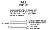
of a mobile phone, and as a display of a digital camera. Fig. 8 shows a schematic view
of the construction of a lightning system called back light system As shown in
the figure, the light from a light source 4 is reflected by a reflector sheet 5 located in the
back position, and goes through a light guide 6, which can introduce the light. After that,
the light is diffused by a diffuser 7, and goes through a back side prism sheet
(longitudinal) 1b and a surface side prism sheet (latitudinal) 1a, and finally illuminates
a liquid crystal display, In the instance shown by the figure, two sheet shaped prisms are
used as optical elements; one is positioned on the surface side and the other is positioned
on the back side. The reason for using such two sheet shaped prisms is described below.
As each of the sheet shaped prisms has a directional function, the brightness of the light
introduced through each prism is enhanced in the different directions. Therefore, by the
use ofthe two sheet shaped prisms, the illumination efficiency is advanced. For example,
Japanese patent application laid open publication No. Heisei 5-203950 (203950/1993)
discloses the structure described below. The structure has plural sheets, and one side of
each of the plural.sheets has many prisms, each of which is triangular in sectional view.
On each of the plural sheets, the edges (ridges) of the triangles are arranged in a parallel
series In the structure, the plural sheets are piled in such a manner that the edges (ridges)
of the triangles form an angle of 5-~85-with each other. By the use of such structure, the
prism system clearly illuminates the LED.
Especially, in the structure in which the light source is positioned at the edge of
the display as shown in Fig. 8, the construction of the sheet shaped optical element is of
prune importance, in order to introduce the light to the center of the display, or to
introduce the light to the surface of the display equally. The light source cannot always
be located at a suitable position to obtain the desired illumination on the display. The
form of the light source can be varied, for example, a point source or a line source.
Therefore, it is necessary to introduce the light suitably by the sheet shaped optical
element, in order to give the proper light distribution on the display.
The aforesaid prior construction shown in Fig. 8 is an example of a back light
system, in which a light source is located on the back side of the display to be
illuminated. Another prior construction has been used also, as front light system in
which a light source is located on the front side of the display. In the front type
construction, a light source 4 is located on the surface side of the display.
The above mentioned layer system is one example of the structures of the sheet
shaped optical elements. Other structures can be applied. For example, the structure can
comprise only three elements; that is, one is a prism sheet, which is preferably rich in
light direction effects and in light collecting effects, another one is a light guide, and the
other one is a reflector. A structure comprising only two sheets of prisms and a reflector
can be used. Any other structure can be used. According to the necessity, the manner of
assembling the sheet shaped optical elements, and how to use them can be determined
variously by the users.
When such sheet shaped optical elements are conveyed to users, or they are
transferred for processing, the sheet shaped optical elements are, in general, packaged and
supported by guard materials. The sheet shaped optical elements have recently become
thinner and smaller in size. Therefore, the package structure is of great importance now.
It is also desired to package the sheet shaped optical elements so as to treat them easily
when they are processed after being transferred, especially when they are picked up to be
processed. In addition, as described above, the manner of constructing sheet shaped
optical elements and what systems use them are varied. Namely, various forms are
required in accordance with various demands.
The kind of sheet shaped optical element package as above mentioned, the
construction of which is shown in Fig. 9 (plan view) and Fig. 10 (section view), has been
generally accepted. This construction consists of small sheet shaped optical elements 1,
for example, lens films which are lenses each made in the shape of a sheet, or a prism
sheet which is a sheet shaped optical element with prism ability, each optical
element being covered by a cover film 31 of equal size. The reason why the equally sized
cover film is used is because the optical element 1 and the cover film 31 are cut at the
same time when they are obtained. The base film 2 serves to support the sheet of the
optical element 1 with the cover film 31. At the same time, the base film serves as a
protection sheet.
In the prior art, the above mentioned sheet shaped optical element package is
formed in a shape corresponding to the shape of the display surface as shown in
the figure, for example rectangular, as in Figure 9. Each sheet shaped optical element is
slantingly arranged on the base film 2 as shown in Fig.9. In other words, a side of each
sheet shaped optical element, for example a longer side of each sheet shaped optical
element, forms a certain angle with the longer side of the base film 2. The reason is that
the specifications of the machines of the users are different from each other For
instance, an angle of 5°, or an angle of 13° may be employed. (Refer to Japanese patent
application laid open publication No. Heisei 5-203950 (203950/1993) mentioned above).
The reason why the optical element 1 has the oblique position mentioned above,
is as follows. It is necessary to give the certain specific direction of refraction to the light
from the light source, like the back light. When the light illuminates the display such as
a liquid crystal display of a mobile phone, it sometimes occurs that a striped vision
appears on the display. This phenomenon is caused by "Moire which is an inequality of
the brightness on the surface ofthe display. The inequality of the brightness occurs by the,
interference generated when the refracted light, introduced in its direction determined by
the sheet shaped optical element 1, goes through the picture elements (dots) of the liquid
crystal cell. The degree of the interference is determined by the size of the picture
elements (dots) ofthe liquid crystal cell, and the angle of incidence for the refracted light.
Therefore, the oir can disappear through the control of either the size or the angle.
Generally speaking, as the size of the picture elements (dots) of the liquid crystal cell is
determined by the resolution of the display, it is considered necessary to give a certain
angle to the sheet shaped optical element, such as a prism sheet, in order to prevent the
appearance of the, oir pattern. In this case, the angle must be given differently according
to the size of the picture elements of the liquid crystal cell. As mentioned above, since
it is desired to illuminate the surface of the display equally, in order to reduce the oir
pattern to a minimum, the sheet shaped optical element 1, such as a prism sheet, must be
given a certain angle in the prior art.
The sheet shaped optical element is generally produced by cutting off a sheet, or
stamping out a sheet from a wide sheet of the material. The material sheet is usually
designed that it refracts the light perpendicularly. Therefore, by giving a certain angle to
the sheet of the material when it is cut, it is possible to provide the optical direction to the
sheet shaped optical element 1. In the prior art, each sheet shaped optical elements 1 is
put on the base film as it is, namely, itmakes an angle with the base film. Consequently,
they are arranged slantingly as shown Fig. 9.
The prior known art described above have difficulties as explained below.
1) They are not suitable for automation, because the products are delivered in a
sheet state in which sheet shaped optical elements are arranged in length and breadth.
2) As the size of the cover film 31 is equal to that of the sheet shaped optical
element, it is not easy to separate them from each other.
3) When they are used in a liquid crystal display system as mentioned above, as
a nature of the products, namely in order to prevent the interference with the liquid crystal
display, a certain angle must be given between the four sides of the base film 4 and the
four sides of the sheet shaped optical element. The angle is, for example, 5°or 13°, but
the value of the angle can be varied according to the desired specification of the products.
Consequently, the direction of the base film 4 is different from that of the sheet shaped
optical element. As a result, it is difficult to treat the products. It is also difficult to pick
up the sheet shaped optical elements in order to process them.
4) As the sheet shaped optical elements are arranged in length and breadth, a
rather wide space is necessary to keep and stock them. Recently, manufacturing lines
have changed from conveyer systems to cell (one person) systems. Therefore, such
necessity for large storage space causes much inconvenience.
It is an object of the present invention to provide a sheet shaped optical element
package, a method of use of sheet shaped optical elements, a method of manufacturing
a sheet shaped optical element package, and a device for manufacturing a sheet shaped
optical element package, which conquer the aforementioned difficulties of the prior art.
Namely, it is an object of the present invention to provide a sheet shaped optical element
package and so on, which are easy to treat, convenient to deliver and supply, easy to treat
the sheet shaped optical element for pick up, easy to process and manufacture, and can
accept an automated lines, and have an advantage concerning storage space.
In the present invention, the object is realized as follows.
The first type of the sheet shaped optical element concerning the present
invention is as follows, and this performs the above object of the present invention:
- the plural sheet shaped optical elements are arranged on the base film in a row;
- each of the sheet shaped optical elements have an optical direction; and
- the above surface of the plural sheet shaped optical elements, are covered by the cover film in a manner such that the cover film covers the sheet shaped optical elements having a blank part on it.
In this specification, the word aving an optical direction means collecting light
and the direction of the collection of the light is a certain specific one.
According to the invention concerning the first type of the sheet shaped optical
element, as the plural sheet shaped optical elements are arranged on the base film in a
row (i.e. in one row), it is convenient to treat them. As each of the sheet shaped optical
elements has the optical direction, namely it has its specific optical direction, illumination
with desired distribution of brightness can be obtained. For example, if is easy to
perform illumination equally to all of the surfaces of the liquid crystal display by
satisfactory brightness. Also desired field of view can be obtained. As the cover film
covers the sheet shaped optical elements with a blank part (margin) on it, it is easy to
discover the cover film and take the sheet shaped optical elements out. As a result, it is
easy to treat the sheet shaped optical elements. It is convenient to supply and use the sheet
shaped optical elements to manufacture or to assemble. As a result, an effective
machine results to which the sheet shaped optical elements are applied. It is advantageous
from the viewpoint of space as they are arranged in a row.
The second type of the sheet shaped optical element package concerning the
present invention is as follows, and this performs the above object of the present
invention:
- the plural sheet shaped optical elements are arranged on the base film in a row;
- each of the sheet shaped optical elements has plural prisms having a sectional view which is a triangle;
- the ridge corresponding to an apex of the triangle of each prism faces an opposite side to a sheet shaped substrate;
- the surface of the prism against the ridge is combined with the sheet shaped substrate as one body;
- the ridge of each prism runs parallel with each other;
- each sheet shaped optical element is supported by being carried by the base film;
and - the surface of each sheet shaped optical element on which the plural prisms are formed is positioned on the opposite side to the base film.
According to the invention concerning the second type of the sheet shaped optical
element, it is possible to concentrate the light into the ridge (edge) of the prisms
mentioned above. Therefore, in the direction that forms a right angle with the ridge (edge)
of the prisms, there occurs a change of the luminance distribution caused by the
concentration of light. But as to the direction along the ridge (edge) of the prisms,
since no, or only a little, light condensing can occur, the affect to the luminance
distribution is small. According to this invention, a different behavior of the
concentration of light is experienced according to difference of the direction. By this,
according to this invention, light having desired brightness distribution can be obtained.
For instance, it is easy to obtain the satisfactory and equal brightness of the light
throughout the whole surface of the liquid crystal display: Also it is possible to get a
particular field of view. In addition; in this invention, as the plural sheet shaped optical
elements are arranged on the base film in a row (in one row), it is easy to treat them. As
a result of the facility, it is convenient to supply and use the sheet shaped optical elements
to manufacture or to assemble. Therefore, an effective machine results to which the sheet
shaped optical elements are applied. It is advantageous from the viewpoint of space as
they are arranged in a row.
The above mentioned sheet shaped optical elements can be applied as-the optical
elements having the specific optical direction used in the first type of the sheet shaped
optical element package described above. Namely, the above mentioned sheet shaped
optical elements used in this invention, that is, the sheet shaped optical elements having
plural prisms whose sectional view is a triangle, the ridge corresponding to an apex of the
triangle of each prism faces the opposite side to a sheet shaped substrate, the surface of
the prism against the ridge is combined with the sheet shaped substrate as one body, and
the ridge of each prism runs parallel with each other, can be used as the optical elements
having the specific optical direction used in the first type of the sheet shaped optical
element package described above.
The third type of the sheet shaped optical element package concerning the present
invention is as follows, and this performs the above object of the present invention:
- the plural sheet shaped optical elements-are arranged on the base film in a row;
- the base film being tape shaped carries the sheet shaped optical elements having a blank part on it;
- each of the sheet shaped optical elements have an optical direction;
- the above surface of the plural sheet shaped optical elements are covered by the cover film in a manner such that the cover film covers the sheet shaped optical elements having a blank part on it; and
- the cover film and the base film hold the plural sheet shaped optical elements between them.
According to the invention concerning the third type of the sheet shaped optical
element, as the plural sheet shaped optical elements are arranged on the base film in a
row (i.e in one row), it is convenient to treat them. As each of the sheet shaped optical
elements has the optical direction, namely it has its specific optical direction, illumination
with desired distribution of brightness can be obtained. For example, it is easy to equally
illuminate all surface of the liquid crystal display by satisfactory brightness. Also, a
desired field of view can be obtained. As the cover film covers the sheet shaped optical
elements with a blank part (margin) on it, it is easy to discover the cover film and take
the sheet shaped optical elements out.
Also, since the cover film and the base film hold the plural sheet shaped optical
elements between them, protection effect is stable and adequate.
Therefore, it is easy to treat the sheet shaped optical elements. It is convenient to
supply and use the sheet shaped optical elements to manufacture of to assemble. As a
result, an effective machine results to the sheet shaped optical elements are applied. It
is advantageous from the viewpoint of space as they'are arranged in a row.
In the first, second and third types of the sheet shaped optical element package
concerning the present invention, the base film can be equal in size to the cover film, and
the base film and the cover film can hold the plural sheet shaped optical elements
between them in a sandwich structure.
In the first, second and third types of the sheet shaped optical element package
concerning the present invention, each of the sheetshaped optical elements has an optical
direction, that is, has light concentration effect into a specific direction. This results in
the following effects.
The sheet shaped optical element plays a role to control the light, for example
light from the source, and provides the illumination to the display by the desired
brightness distribution, generally, brightness distribution that equally illuminates all of
the surfaces of the display. In some cases, it provides the brightness distribution that
produces local illumination, or different brightness between a character part and a graphic
part. By the nature of the optical direction that collects the light to the specific direction,
such an equal all surface illumination or local illumination to the particular part locally
can be easily performed. Also, a desired angle of the scope of the field of view can be
easily and conveniently realized. For instance, in the mobile phone, as the display of it
is seldom seen from a slanted position unlike the- display of television set, the angle of
the scope of the field of view is not necessarily so wide. However, for example, the
display of the small size game console may be seen by many persons from side positions.
In such an instance, the angle of the scope of the field of view is desired to be wide. Also,
the display commonly seen from the vertical position, for example, the display usually
seen from the upper position such as the data display located below which must be seen
from the upper driver position of the vehicle of the railway, the angle of the scope of the
vertical field of view is desired to be wide.
Concerning the angle of the scope of the field of view, there are also various
demands, as described above. These demands can be accomplished by controlling the
distribution of the brightness to provide a requested illumination. In such a case, it is very
effective to provide the collecting effect that introduce the light to the specific direction.
Especially, the aforementioned sheet shaped optical element used in the second type of
the sheet shaped optical element package, is effective for controlling the distribution of
the brightness. That is, the sheet shaped optical element having, plural prisms whose
sectional view is a triangle, the ridge corresponding to an apex of the triangle of each
prism faces the opposite side to a sheet shaped substrate, the surface of the prism against
the ridge is combined with the sheet shaped substrate as one body, and the ridge of each
prism runs parallel with each other, is effective for controlling the distribution of the
brightness. By various designs, various optical directions can be obtained. Therefore, a
desired distribution of the brightness can be easily achieved. The instance constructed
such that two sheets of sheet shaped optical element are used, refer to the explanation
described about present, example 2 and after that, is preferable. But the sheet shaped
optical element with a large light collecting effect can be satisfactorily used
without requiring the use of two sheets, and can provide the desired distribution of the
brightness.
The fourth type of the sheet shaped optical element package concerning the
present invention is as follows, and by this, the above object of the present invention is
performed:
- the plural sheet shaped optical elements are arranged on the base film in a row;
- the base film and the cover film hold the sheet shaped optical elements, between them; and
- by rolling up by the upper and lower rollers, the sheet shaped optical elements can be picked out.
According to the invention concerning the fourth type of the sheet shaped optical
element, as the plural sheet shaped optical elements are arranged on the base film in a
row (i.e. in one row), it is convenient to treat them. Also, as the cover film and the base
film holds the plural sheet shaped optical elements between them, protection effect is
stable and adequate.
In addition, since the upper roller rolls up the cover film and a lower roller rolls
up the cover film, and by the rolling up by the both rollers, the sheet shaped optical
elements can be picked out, as a result, it is easy to treat the sheet shaped optical
elements. It is convenient to supply, and use the sheet shaped optical elements to
manufacture or to assemble. It is advantageous from the view of space as they are
arranged in a row.
In the fourth type of the sheet shaped optical element package concerning the
present invention, the plural sheet shaped optical elements in a row can be covered by the
cover film in a manner that the cover film covers the them haying a blank part (margin)
on it, and the cover film and the base film holds the plural sheet shaped optical elements
between them.
In the fourth type of the sheet shaped optical element package concerning the
present invention, the base film and the cover film can hold the plural sheet shaped
optical elements between them in a sandwich structure.
In the fourth type of the sheet shaped optical element package concerning the
present invention, the sheet shaped optical element can have the optical direction. And
as each of the sheet shaped optical elements, it can be used as described next. That is, the
sheet shaped optical element which has plural prisms whose sectional view is a triangle,
the ridge corresponding to an apex of the triangle of each prism faces the opposite side
to sheet shaped substrate, the surface of the prism against the ridge is combined with the
sheet shaped substrate as one body, and the ridge of each prism runs parallel with each
other.
In the fourth type of the sheet shaped optical element package concerning the
present invention, the following structure can be used. Namely, the structure in which the
plural sheet shaped optical elements being arranged on the base film in a row, and the
base film and the cover film hold the sheet shaped optical elements between them, is
rolled up to form reel shape, or the structure is folded to form a Z shape in a unit of each
sheet shaped optical element.
A method of use of sheet shaped optical elements is as follows, and this performs
the above object of the present invention:
In this invention, "use" means picking up the sheet shaped optical elements using
sheet shaped optical element package delivered, and supplying them, manufacturing
them, or assemble them and the like.
According to this invention, as the plural sheet shaped optical elements are
arranged on the base film in a row (i.e. in one row), it is convenient to treat them. Also
as the cover film and the base film hold the plural sheet shaped optical elements between
them, protection effect is stable and adequate.
In addition, since the upper roller rolls up the cover film and a lower roller rolls
up the cover film, and by the rolling up by the both rollers, the sheet shaped optical
elements can be picked out, and as a result, it is easy to treat the sheet shaped optical
elements. It is convenient to supply, and use the sheet shaped optical elements to
manufacture or to assemble. It is advantageous from the viewpoint of space as they are
arranged in a row.
In the method of use of sheet shaped optical elements, the above surface of the
plural sheet shaped optical elements in a row can be covered by the cover film in a
manner such that the cover film covers the sheet shaped optical elements having blank
part on it, and the cover film and the base film can hold the plural sheet shaped optical
elements between them.
In the method of use of sheet shaped optical elements, the base film and the cover
film can hold the plural sheet shaped optical elements between them in a sandwich
structure.
In the method of use of sheet shaped optical elements, the sheet shaped optical
element can have the optical direction. As each of the sheet shaped optical elements, it
can be used as described next. That is, the sheet shaped optical element which has plural
prisms whose sectional view is a triangle, the ridge corresponding to an apex of the
triangle of each prism faces to the opposite side to sheet shaped substrate, the surface of
the prism against the ridge is combined with the sheet shaped substrate as one body, and
the ridge of each prism runs parallel with each other.
In the method of use of sheet shaped optical elements, the following structure can
be used. Namely, the structure in which the plural sheet shaped optical elements being
arranged on the base film in a row, and the base film and the cover film hold the sheet
shaped optical elements between them, is rolled up to form reel shape, or the structure
is folded to form a Z shape in a unit of each sheet shaped optical element.
The first type of the method of manufacturing a sheet shaped optical element
package is as follows, and by this, the above object of the present invention is performed:
and
or;
wherein:
In this invention, "convey" means to transfer by belt or the like, "stock" means
to store in a box or the like and in necessary, taking out from there.
According to the- invention concerning this method of manufacturing a sheet
shaped optical element package, it can be easy and conveniently performed to
manufacture a sheet shaped optical element package to use for producing a sheet shaped
optical elements assembly comprising at least the structure in which the first sheet shaped
optical element, and the second sheet shaped optical element, whose optical direction
makes a right angle with the optical direction of the first sheet shaped' optical element,
are piled in this order. It is also possible to automate the process.
In the method of manufacturing a sheet shaped optical element package,
following embodiment can be applied.
In the invention, the other element(s) necessary to be constructed into the sheet
shaped optical elements assembly is (are) placed in a position next to the second sheet
shaped optical element on the base film in the order corresponding to the pile order; and
the sheet shaped optical,element package is obtained in which the first sheet shaped optical element, the second sheet shaped optical element whose optical direction makes a right angle with the optical direction of the first, sheet shaped optical element, and the other necessary element(s) are piled in this order between the base film and the cover film.
the sheet shaped optical,element package is obtained in which the first sheet shaped optical element, the second sheet shaped optical element whose optical direction makes a right angle with the optical direction of the first, sheet shaped optical element, and the other necessary element(s) are piled in this order between the base film and the cover film.
In the method of manufacturing a sheet shaped optical element package,
following embodiment can be applied.
In the invention, the first sheet shaped optical element and the second sheet
shaped optical element both have plural prisms having a sectional view which is a
triangle, the ridge corresponding to an apex of the triangle of each prism faces the
opposite side to a sheet shaped substrate, the surface of the prism against the ridge is
combined with the sheet shaped substrate as one body, and the ridge of each prism runs
parallel with each other; and
the first sheet shaped optical element and the second sheet shaped optical element are conveyed or stocked in a condition such that the directions of the ridges of the prisms are in the same.
the first sheet shaped optical element and the second sheet shaped optical element are conveyed or stocked in a condition such that the directions of the ridges of the prisms are in the same.
In the method of manufacturing a sheet shaped optical element package,
following embodiment can be applied.
In the invention, at least one of the diffusion sheet, light guide, and reflector sheet
is placed in a position next to the second sheet shaped optical element on the base film,
film; and
the sheet shaped optical element package is obtained in which the first sheet shaped optical element, the second sheet shaped optical element whose optical direction makes,a right angle with the optical direction of the first sheet shaped optical element, and at least one of the diffusion sheet, light guide, and reflector sheet are piled in this order between the base film and the cover film.
the sheet shaped optical element package is obtained in which the first sheet shaped optical element, the second sheet shaped optical element whose optical direction makes,a right angle with the optical direction of the first sheet shaped optical element, and at least one of the diffusion sheet, light guide, and reflector sheet are piled in this order between the base film and the cover film.
The first type of the device for manufacturing a sheet shaped optical element
package is as follows, and by this, the above object of the present invention is performed:
A device for manufacturing a sheet shaped optical element package to use for producing a sheet shaped optical elements assembly comprising at least a structure in which a first sheet shaped optical element, and a second sheet shaped optical element, whose optical direction makes a right angle with the optical direction of the first sheet shaped optical element, are piled in this order, the device comprises:
A device for manufacturing a sheet shaped optical element package to use for producing a sheet shaped optical elements assembly comprising at least a structure in which a first sheet shaped optical element, and a second sheet shaped optical element, whose optical direction makes a right angle with the optical direction of the first sheet shaped optical element, are piled in this order, the device comprises:
In the method of the first type of the device for manufacturing a sheet shaped
optical element package, following embodiment can be applied.
In the invention, the first sheet shaped optical element and the second sheet
shaped optical element both have plural prisms having a sectional view which is a
triangle, a ridge corresponding to an apex of the triangle of each prism faces the opposite
side to a sheet shaped substrate, a surface of the prism against the ridge is combined
with a sheet shaped substrate as one body, and the ridge of each prism runs parallel with
each other; and
the first sheet shaped optical element and the second sheet shaped optical element are placed on the base film in a condition such that the directions of the ridges of the prisms of the second sheet shaped optical element make a right angle with the ridges of the prisms of the first sheet shaped optical element.
the first sheet shaped optical element and the second sheet shaped optical element are placed on the base film in a condition such that the directions of the ridges of the prisms of the second sheet shaped optical element make a right angle with the ridges of the prisms of the first sheet shaped optical element.
According to the invention concerning the first type of the device for
manufacturing a sheet shaped optical element package, it can be easy and conveniently
performed to manufacture a sheet shaped optical element package to use for producing
a sheet shaped optical elements assembly comprising at least the structure in which the
first sheet shaped optical element, and the second sheet shaped optical element, whose
optical direction,makes a right angle with the optical direction of the first sheet shaped
optical element are piled in this order. It is also possible to automate the process.
The second type of the method of manufacturing a sheet shaped optical element
package is as follows, and by this, the above object of the present invention is performed:
A method of manufacturing a sheet shaped optical element package, the method
comprising:
According to the invention concerning this method of manufacturing a sheet
shaped optical element package, it can be easy and conveniently performed to
manufacture a sheet shaped optical element package to use for producing a sheet shaped
optical elements assembly comprising at least the structure in which the first sheet shaped
optical element, and the second sheet shaped optical element, whose optical direction
makes a right angle with the optical direction of the first sheet shaped optical element,
are piled in this order. It is also possible to automate the process.
In this method of manufacturing a sheet shaped optical element package
described above, following embodiment can be applied.
In the invention, the first sheet shaped optical element and the second sheet
shaped optical element both have plural prisms whose sectional view is a triangle, the
ridge corresponding to an apex of the triangle of each prism faces the opposite side to a
sheet shaped substrate, the surface of the prism against the ridge is combined with the
sheet shaped substrate as one body, and the ridge of each prism runs parallel with
each other;
the first sheet shaped optical element and the second sheet shaped optical element are conveyed or stocked in a condition such that the directions of the ridges of the prisms are in the same.
the first sheet shaped optical element and the second sheet shaped optical element are conveyed or stocked in a condition such that the directions of the ridges of the prisms are in the same.
The second type of the device for manufacturing a sheet shaped optical element
package is as follows, and by this, the above object ofthe present invention is performed:
According, to the invention concerning the second type of the device for
manufacturing a sheet shaped optical element package, it can be easy and conveniently
performed to manufacture a sheet shaped optical element package to use for producing
a sheet shaped optical elements assembly comprising at least the structure in which the
first sheet shaped optical element, and the second sheet shaped optical element whose
optical direction makes a right angle with the optical direction of the first sheet shaped
optical element are piled in this order. It is also possible to automate the process.
In this device of manufacturing a sheet shaped optical element package described
above, following embodiment can be applied.
In the invention, the-first sheet shaped optical element and the second sheet
shaped optical element both have plural prisms whose sectional view is a triangle, the
ridge corresponding to an apex of the triangle of each prism faces the opposite side to a
sheet shaped substrate, the surface of the prism against the ridge is combined with the
sheet shaped substrate as one body, and the ridge of each prism runs parallel with
each other;
the first sheet shaped optical element and the second sheet shaped optical element are conveyed or stocked in a condition such that the directions of the ridges of the prisms are the same.
the first sheet shaped optical element and the second sheet shaped optical element are conveyed or stocked in a condition such that the directions of the ridges of the prisms are the same.
The third type of the method of manufacturing a sheet shaped optical element
package is as follows, and by this, the above object of the present invention is performed:
According to the invention concerning this method of manufacturing a sheet
shaped optical element package, it can be easy and conveniently performed to
manufacture a sheet shaped optical element package having the structure where the sheet
shaped optical element and other necessary element(s) are piled on the base film directly.
It is also possible to automate the process.
The third type of the method of manufacturing a sheet shaped optical element
package is as follows, and by this, the above object of the present invention is performed:
According to the invention concerning this method of manufacturing a sheet
shaped optical element package, it can be easy and conveniently performed to
manufacture a sheet shaped optical element package, that has the structure where the
effective sheet shaped optical element with above mentioned prism and other necessary
element(s) are piled on the base film directly. It is also possible to automate the process.
The specification of Japanese patent application laid open publication No. Heisei
5-203950 (203950/1993) describes an optical elements packaging body which can easily
distinguish the front side from the back side of the elements. However there is not any
description concerning the optical direction, the assembling of the packaging body,itself,
nor the convenience at the time of treating or placing the elements using the packaging
body.
Fig. 1 is a front view of a sheet shaped optical element package of example 1 of
the present invention.
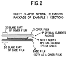
Fig. 2 is a sectional view of a sheet shaped optical element package of example
1 of the present invention.
Fig. 3 illustrates an embodiment of a supplying form of a package of example 1
of the present invention ( single reel form and z-shaped folding form).
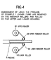
Fig. 4 illustrates an embodiment of using the package of example 1 of the present
invention ( cover films are removed by the remover rollers and rolled up by the rollers).
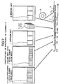
Fig. 5 illustrates a construction of packaging ofthe sheet shaped optical elements
in example 2 of the present invention.
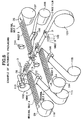
Fig. 6 illustrates an example of automatic packaging of the sheet shaped optical
elements, and illustrates a device for manufacturing a sheet shaped optical element
package.
Fig. 7 illustrates a construction of packaging of example 3 of the present
invention.
Fig. 8 illustrates a prior art.
Fig. 9 is a front view of a prior art package construction.
Fig. 10 is a sectional view of a prior art package construction.
Fig. 11 is a sectional view of a sheet shaped optical element package of example
4 of the present invention.
Fig. 12 illustrates a construction of packaging of the sheet shaped optical
elements in example 4 of the present invention.
Fig. 13 is a fragmentary view of a device for manufacturing a sheet shaped optical
element package of example 4 of the present invention.
Fig. 14 illustrates a sheet shaped optical element used in examples of the present
invention.
Below, the preferred embodiments are described in detail referring to the
drawings. The embodiments described hereafter, however, do not limit the present
invention.
The first example is an embodiment in which the present invention is applied to
a sheet shaped optical element package used in a back light system. The back light system
lights a panel of liquid crystal display of a mobile phone, a hand terminal of the
information system (i.e., PDA), a digital camera, a hand game machine, and the like. In
this example, a prism sheet, having light collecting effects and light refracting effects, is
used as a sheet shaped optical element. The collecting effects and the light refracting
effects of the sheet shaped optical element (prism sheet) used in this example are
designed in such a manner that the light from the source is distributed throughout the
whole surface of the display equally. It is possible, however, to design the effects in order
to obtain any other desired light distribution on the display surface according to necessary
specifications.
The first embodiment is depicted in figures 1 to 4. In this example, each of the
package products has a form in which element(s) between protection sheets (base film
2 and cover film 3) are arranged in a same direction. In this embodiment, sheet shaped
optical elements are all arranged all in the same direction as shown in Fig. 1, and are
packaged like a wrapper form between the-protection sheets.
As shown in Figs. 1 and 2, in the sheet shaped optical element package P, plural
sheet shaped optical elements 1 are arranged in the form of a line on a base film 2 as
mentioned above. The base film 2 is tape shaped, and it carries the arranged sheet shaped
optical elements in a manner as discussed next. Namely, the part other than a part where
the sheet shaped optical elements are placed, is kept as a blank part (margin) 20 on the
surface of the base film 2. Likewise, the cover film 3 covers the arranged sheet shaped
optical elements kept as the blank part (margin) 30. That is, each sheet shaped optical
element is wrapped by the cover film 3 having the blank part (margin) 30. Consequently,
it is easy to take out the sheet shaped optical element from the wrapper by removing the
cover film 3. Similarly, it is easy to separate the base film from the sheet shaped optical
element.
The base film 2 and the cover film 3 used in this example are the same size both
in width and length. Between the base film 2 and the cover film 3, both having the same
shape, sheet shaped optical elements are placed like a sandwich construction.
As mentioned earlier, since the base film 2 and the cover film 3 carry sheet shaped optical
elements with blank parts.(margins) 20, 30, the sheet shaped optical elements never lay
bare. In addition, it is possible that the sheet shaped optical elements are protected against
outside contamination. They are surely protected in this example.
Each sheet shaped optical element 1 in the sheet shaped optical element package
P in this example is a prism sheet as constructed below. The prism sheet has a certain
specific light direction for the following reason.
Referring to Fig. 14, on one side surface of each sheet shaped optical element 1
used in this example, there are formed plural prisms 131a, 131b, tc., each sectional view
of which is a triangle. The ridge (edge) 132a, 132b, tc., corresponding to an apex of the
triangle of each prism faces toward the opposite side to the sheet shaped substrate 130.
That is to say, each prism faces toward the upper side of the drawing. The surface of the
prism against the ridge (edge) is combined with the sheet shaped substrate 130 as one
body. In this example, many prisms 131a, 131b, tc., having a triangle shape in sectional
view, are formed on the sheet shaped substrate 130, and are formed into a prism sheet.
The ridge (edge) 132a, 132b, tc., of each prism runs parallel to one another. Each
sheet shaped optical, element 1 is supported in such a way that the base film 2 carries it.
The surface on which the prisms 131a, 131b, tc., are formed is located in the sheet
shaped optical element package on the opposite side to the base film 2. That is, the
surface on which prisms are formed is located on the upper side of Fig.2.
The detailed structure of the sheet shaped optical element 1 used in this example
is as follows. The summit angle of the prism is 90°. The summit angle is an angle of the
triangle in the sectional view corresponding to the ridge (edge) 132a, 132b, tc., of prism
131a, 131b, tc. The prism pitch is 50 µm. That is to say, twenty prisms are formed within
one mm. A large number of prisms are formed in such a manner. The sheet shaped
substrate 130 is made from transparent resin such as polyester resin. Each prism
131a, 131b, tc., is-made-from resin-having an excellent optical nature such as transparent
acrylic resin. The prisms 131a, 131b, tc., made from transparent resin-are formed as one
body on the shaped substrate 130 which is made from resin. Consequently, the sheet
shaped optical element, 1 in this example is formed. The thickness of the sheet shaped
substrate 130 is approximately 120 µm, and the thickness of the sheet shaped substrate
130 containing prisms 131a, 131b, tc., is 150 µm.
The sheet shaped optical element 1 is constructed in such a manner that the light
from the back light source (from the direction of the shaped substrate 130) is, after
refraction and reflection, collected mainly to the ridge (edge) 132a, 132b, tc., of prism
131a, 131b, tc. Consequently, the light is controlled and collected on the ridge (edge)
132a, 132b, tc., of prism 131a, 131b, tc. As a result, brightness on it is enhanced in the
direction that is orthogonal to the ridge (edge), i.e the Y direction in the drawing. In the
distribution of light in the direction along the ridge of the triangular prism, i.e. the X
direction in the drawing, the effect of the collection of light is rather weak.
The ratio of advance of the brightness of the light, is set as 1.5. In this
specification, the ratio of advance of the brightness of the light means a rate of advance
of the brightness in comparison with the brightness of the light when the sheet shaped
optical element 1 is not used. Therefore, the collecting effect in this example gives
enhancement of 50% of the brightness of the light.
As described later, there is a case in which two sheets of the sheet shaped optical
element 1 are used in such a manner that the optical directions are orthogonal to each
other, namely the ridges 132a, 132b, tc., of prisms 131a, 131b, tc., make a right angle
to each other. By using such a manner, the ratio of advance of the brightness of the
light is 2.0. That is, the brightness is doubled.
It is possible to adjust the angle of the field of view by using the sheet shaped
optical element 1 with a specific optical direction. In this example, when the sheet shaped
optical element 1 is used in such a manner that the direction of the ridges 132a, 132b,
tc., of prisms 131a, 131b, tc., as mentioned above, is arranged along the up and down
direction on the display, the angle of the field of view can be adjusted to ±50° in the
horizon. In other words, within the view scope between 50° right or left from the normal
position, from any direction, the display can be seen clearly.
Perpendicularly, the angle of the field of view is within ±35° in this example. The
angle of the field of view, in this specification, is determined by brightness that is
50% lower compared with the brightness given when seeing the display squarely.
The sheet shaped optical element package P in this example can be conveyed,
stocked, and delivered as follows.
The embodiment shown in Fig. 3(a) is an example in which the optical element
package P is arranged in the form of a single line film, and is rolled up into a reel shape.
The embodiment shown in Fig. 3(b) is an example in which the optical element
package P is folded into a form of a Z shape, in which a unit of it contains one set of
sheet shaped optical element 1, base film 2, and cover film 3.
In both embodiments, the optical element package P can be stocked and kept, and
they are easily conveyed and delivered. The embodiments are both very convenient.
Fig.4 shows an example of the state when the sheet shaped optical element 1 is
taken out, in order to use the element 1 to be assembled, from the sheet shaped optical
element package P. In this example, the upper roller 91 used to roll up the cover film 3
is placed above the sheet shaped optical element package P, and the lower roller 92 used
to roll up the base film 2 is placed below the sheet shaped optical element package P, as
shown in the drawing. The sheet shaped optical element package P is located between the
upper remover roller 93 positioned near the cover film 3 side, and the lower remover
roller 92 positioned near the base film 2 side. When the sheet shaped optical element
package P runs between the remover rollers 92, 93, the cover film 3 is removed from the
package P by the upper remover roller 93 and reeled off by the upper roller 91, and at the
same time the base film 2 is removed from the package P by the lower remover roller 92
and reeled off by the lower roller 92.
At that time, as the sheet shaped optical element is carried by the cover film 3 and
the base film 2 each of which has blank part (margin) 20, 30, the blank part (margin) 20,
30 makes room for handling and, as a result, it is easy to remove the films 2, 3 from the
sheet shaped optical element package P. Thus, the films 2, 3 can be removed and the
sheet shaped optical element can be taken out conveniently without difficulties.
By removing the base film 2 and the cover film 3 as described above, the sheet
shaped optical element 1 is taken out to be used.
In this example, the sheet shaped optical element 1 is used to get the liquid crystal
display structure shown in Fig.8. In this example, either one sheet of the sheet shaped
optical element 1 can be used to complete the structure, or two sheets of the sheet shaped
optical element 1 whose optical directions are orthogonal to each other can be used to
complete the structure. In generally, it is effective to use a pair of sheet shaped optical
elements that are, in optical direction, orthogonal to each other. As a result, the brightness
is enhanced and the illumination on the display is made consistent. But, as in this
example, the employment of one sheet of prism, which is efficient in light collecting and
which corresponds to the optical direction, provides satisfactory results to a specific use.
As mentioned above, it is easy to treat the sheet shaped optical element and its
package in this example. The sheet shaped optical element is protected sufficiently and
stably. Supply, assemble, and affixing of the sheet shaped- optical elements can be
conveniently performed. Since they are arranged in one line form, it is advantageous in
regard to space.
Referring to Figs. 5 and 6, provided next is a description of the second example
of the present invention.
In this example, an assembly is provided having at least the first sheet shaped
optical element 1a, and the second sheet shaped optical element 1b whose optical
direction is orthogonal to that of the first sheet shaped optical element 1a. In the
assembly, the second sheet shaped optical element 1b is arranged on the first sheet shaped
optical element 1a.
In this example referring to Fig. 5, the sheet shaped optical element 1a, the sheet
shaped optical element 1b whose optical direction is orthogonal to that of the sheet
-shaped optical element 1 a, and the other elements necessary to construct the sheet shaped
optical element package P, such as the refractory sheet 7, are conveyed in the direction
D2 orthogonally oriented to the direction D 1 of the base film 2 on which the elements are
to be placed. Thus, the sheet shaped optical element 1a, the sheet shaped optical element
1b, and other elements such as the refractory sheet 7 are placed in this order on the base
film 2.
Although each sheet shaped optical element 1a, sheet shaped optical element 1b,
and refractory sheet 7, and other element(s) are delivered in three rows as shown in
the drawing, they can be provided in any number of rows such as, for example, in one
row. The number of row(s) of the sheets can be different from that of another Finally
they must be placed on the base film 2 in proper order.
In this invention, the first sheet shaped optical element 1a and the second sheet
shaped optical element 1b are conveyed or stocked in a condition such that both elements
are in the same optical directions. According to the invention, in this example, the first
sheet shaped optical element 1a and the second sheet shaped optical element 1b are
conveyed in a condition such that both optical directions are all the same.
Both the first sheet shaped optical element 1a and the second sheet shaped optical
element 1b are, as shown by vertical lines in Fig.5, conveyed in a condition such that both
optical directions are all the same.
In this example, the first sheet shaped optical element 1a, conveyed in the
direction D2, is rotated 90° to the conveyed direction, and then is put on the base film 3.
The second sheet shaped optical element 1b is then placed without rotation on the next
position of the base film 3, and they are formed into one row.
Consequently, the first sheet shaped optical element 1a and the second sheet
shaped optical element 1b are arranged on the base film 3 in a manner such as their
optical directions are orthogonal to each other.
In this example, the first sheet shaped optical element 1a is conveyed along the
direction D2. That is, the longitudinal direction of the element 1a at the time when it
is conveyed is the same as D2. The second sheet shaped optical element 1b is conveyed
across the direction D2. That is, the longitudinal direction of the element 1b at the time
when it is conveyed, is orthogonal to D2. Either of the elements 1a or 1b, and the element
1a in this example is rotated 90° and placed on the base film 2 as mentioned above. As
a result, longitudinal directions of the elements 1a, 1b on the base film are all the same.
Since both sheet shaped optical elements 1a, 1b have the same shape, the two elements
1a, 1b can be piled in the same position on the base film 2. As a result, the obtained
package is convenient to use at the time when the sheet shaped optical elements 1a, 1b
in it are picked up and are assembled afterward.
As shown in the drawing, in this example, the first sheet shaped optical element
1a is rotated 90° when it is picked up and placed on the base film. The second sheet
shaped optical element 1b does not change its direction when it is picked up and put on
the next position on the base film. However, the reverse can be accepted, that is, the first
sheet shaped optical element 1a can be placed on the base film in its direction, and the
second sheet shaped optical element 1b can be rotated 90° and put on the base film.
According to the necessary mechanical specification, convention in the after process,
users demands, and the like of, any embodiment can be accepted.
The refractory sheet 7 which is put on next is rotated 90° in this example. The
necessity of such rotation is also determined by the accepted direction of the sheet 7.
As mentioned above, the sheet shaped optical element 1a, the sheet shaped
optical element 1b, and other elements such as refractory sheet 7 are arranged in one row.
Thus, the sheet shaped optical elements package is obtained.
In order to prepare the light system shown in Fig. 8 by using the above sheet
shaped optical elements package, the process can be completed only by piling the
elements according to their positional order. It is very easy and convenientto assemble
them to get the products. It is possible to prevent damage on the surface of the sheet
shaped optical element 1a, 1b. The rate of occurrence of the defects of an appearance of
the products also decreases. An error in assembling can also be prevented, and the
stability of the quality of the products is enhanced. The time necessary to assemble can
be shortened. For example, when the process is mechanized, the necessary time of the
process can be shortened by several times in comparison with the manual prior process.
The labor cost can be reduced, and thus, the products can be obtained at a much lower
cost.
The following is an explanation concerning optical directions of the sheet shaped
optical element 1a and the sheet shaped optical element 1b used in this example. Both of
the sheet shaped optical element 1a and the sheet shaped optical element 1b are efficient
in light collecting.
An optical direction of an optical element device (i.e., the direction to which the
light, especially the light from the source, is introduced) is provided by any means, for
example, through a refractory material or the like. In this specification, the optical
direction means the direction to which the light is collected.
The nature of the optical direction of the optical element can be employed to give
the equal illumination on the whole display surface when the light is introduced from a
point or a line source. The light from the point source is, for example, a light from an
LED element, of a lamp. The light from the line source is, for example, light from a
fluorescent light tube, or a line shaped LED element. The decision of the optical
direction, namely, from what direction the light should be collected, differs in accordance
with the position of the light source, and with the requested distribution of brightness on
the display. It cannot be determined in one manner. Generally, it is desired to illuminate
the whole surface of display equally with sufficient brightness. Therefore, in this
example, the direction that provides such illumination is accepted. Other manners can be
used such as a certain specific part, for example, the part in which letters appear, or the
part in which images appear, should be specially illuminated. The direction that provides
special brightness to a local area of the display can be employed according to the
specification.
In this example, optical directions of the sheet shaped optical element 1a and the
sheet shaped optical element 1b form a right angle. By the structure, the brightness on the
surface of the display is enhanced. It also provides a desired degree of field of view
necessary to see the display clearly.
Detailed structure of each sheet shaped optical element 1a and the sheet shaped
optical element 1b used in this example is as follows. Each element is a prism sheet
constructed as discussed below. Each has a specific optical direction.
Referring to Fig. 14, each-sheet shaped optical element 1a and the sheet shaped
optical element 1 b used in this example is constructed as shown by sheet shaped optical
element 1. Plural prisms 131 a, 131b, tc., each sectional view of which is a triangle, are
formed on the one side (the upper side) of the sheet shaped substrate 130. The ridge
(edge) 132a, 132b, tc., corresponding to an apex of the triangle of each prism, faces
the side opposite to the sheet shaped substrate 130. That is, it faces the upper side of the
drawing. The surface of the prism against the ridge (edge) is combined with the sheet
shaped substrate 130 as one body. In this example, many prisms 131a, 131b, tc , the
sectional view of each of which is a triangle shape, are formed on the sheet shaped
substrate 130, and are formed into a prism sheet.
The ridge (edge) 132a, 132b, tc., of each prism runs parallel to one another. The
vertical lines illustrated on each sheet shaped optical element 1a and the sheet shaped
optical element 1b in Fig.5 are ridge (edge) lines of the prisms. As-shown in Fig.5, they
are placed on the base film 2 in such a manner so that their optical directions are
orthogonal to each other. The surface side on which the prisms 131a, 131b, tc., are
formed is located on an opposite side of the base film 2 in the sheet shaped optical
element package. That is, the prism side is on the upper side (i.e. on the side of the paper
face on which a drawing is illustrated).
The angle of the prism of this sheet shaped optical element, (i.e. the angle of the
apex of the sectional view, a triangle, corresponding to ridge (edge) 132a, 132b, tc., of
prism 131a, 131b, tc.,) is 90°. The prism pitch is 50 µm. Namely, twenty prisms
131a, 131b, tc., are formed within one mm in width. A large number of prisms are
formed in such a manner. The sheet shaped substrate 130 is made from transparent resin
such as polyester resin. Each prism 131 a, 131b, tc., is -made from resin that has an
excellent optical nature such as transparent acrylic resin. The prisms 131a, 131b, tc.,
made from transparent resin are formed as one body on the sheet shaped substrate 130
made from resin and, as a consequence, the sheet shaped optical element 1 in this
example is formed. The thickness of the sheet shaped substrate 130 is approximately 120
µm. The thickness of the sheet shaped substrate 130 containing prisms 131a, 131 b, tc.,
is 150 µm.
This sheet shaped optical element is constructed in such a manner that the light
from the back light source (from the side of the shaped substrate 130) is, after refraction
and reflection, collected mainly to the ridge (edge) 132a, 132b, tc., of prism 131a, 131b,
tc. Consequently, the light is controlled and collected on'the ridge (edge) 132a, 132b, tc.,
of prism 131a, 131b, tc. As a result, brightness on the ridge (edge) is enhanced. In the
distribution of light in the direction along the ridge of the triangular prism (i.e., the X
direction in the drawing), the effect of the collection of light is rather weak.
In this example, the ratio of advance of the brightness of the light is set as 1.5. A
ratio of advance of the brightness of the light means a rate of advance of the brightness
in, comparison with the brightness of the light when the sheet shaped optical element 1
is not used. Therefore, the collecting effect of the light in this example provides, by using
one sheet of the sheet shaped optical element, an enhancement of 50% of the brightness
of the light. (This data is obtained when an LED is used as a light source.) In addition,
in this example, two sheets of the sheet shaped optical element are used in such a manner
that the optical directions are orthogonal to each other. As a result of this arrangement,
the ratio of an enhancement of the brightness of the light become 2.0. That is, the
brightness becomes doubled. Similarly in a foregoing example, the field of view can be
controlled likewise in this example.
In this example, as shown in Fig 5, two sheets of the sheet shaped optical element
are put on the base film in such a manner that the ridge (edge) 132a, 132b, tc., of prism
131a, 131b, tc., of the one sheet makes a right angle with the ridge (edge) 132a, 132b,
tc., of prism 131a, 131b, tc., of the other sheet. As a result, it become easy to pile the two
sheets of the sheet shaped optical element in such a manner that the ridges (edges)
132a, 132b, tc., of prisms 131a, 131b, tc., make a right angle.
Hereafter, the automatic process of the packaging system is-described referring
to Fig. 6.
Fig. 6 shows a device used in this example for the packaging process. In the
drawing, a base film-2 is provided. In the example shown in Fig. 6, the base film 2, which
is rolled up by the supply roller 101, is conveyed along the direction D3. The base film
2 is plane on the way of transferring. In this condition, a sheet D is put on the base film
2. Then a sheet C is put on the base film 2, then a sheet B is put on the base film 2. Then
a sheet A is put on the base film 2. As a result, the construction in which the sheets A, B,
C, and D are arranged in a line on the base film 2 in this order is obtained. Further, the
cover film is placed on the obtained construction. The obtained construction is rolled up
by the reel up roller 102 again, and is stocked or delivered as a complete packaging
product.
The sheet D is stocked in a storage box 103, and is picked up from the box 103,
then is rotated as needed, and is placed on the base film.
The sheet C is supplied in such a condition that the sheet C is placed on an
original belt C. The original belt C runs from the roller 104, that rolled up the original
belt C, to the base film 2 in the direction D4. The direction D4 forms a right angle with
the direction D4 in which the base film runs. Near the base film 2, a sheet C on the
original belt C is picked up, then is rotated as needed, and then is placed on the base film
2. After the sheet C is picked up, the original belt C is turned in its direction and rolled
up by the roller 105. A feed roller 106 introduces the original belt C to the roller 105.
The sheet B is supplied similarly as the aforementioned sheet C to the base film
2. In the drawing, the original belt B, on which the sheet B is placed, is supplied from the
opposite or counter side to that of the original belt C of the base film 2 because the
positions from which the original belt B, C is supplied are located on the opposite or
counter sides of the base film from each other. In this example, the sheet B is supplied
to-the base film 2 from the right side of the drawing, and the sheets A and C are supplied
to the base film 2 from the left side, namely, the sheets are supplied from both sides
alternately.
The sheet B is supplied in the condition that the sheet B is put on the original belt
B. The original belt B runs from the roller 107 which rolled up the original belt B, to the
base film 2 in the direction D5. The direction D3, in which the base film runs, and the
direction D5 of the original belt B form a right angle. As the sheet B is positioned in the
opposite side to the sheet C, the sheet B runs from the opposite position to that of the
sheet C. Near the base film 2, a sheet B on the original belt B is picked up, then is
rotated as needed, and then is placed on the base film 2. After the sheet B is picked up,
the original belt B is turned in its direction and rolled up by the roller 108. A feed
roller 109 introduces the original belt B to the roller 108.
The sheet A is supplied along the same direction as the sheet C, and placed on
the base film similarly as the sheet C mentioned above.
That is to say, the sheet A is supplied in the condition that it is put on an original
belt A. The original belt A runs from the roller 110, which rolled up the original belt A,
to the base film 2 in the direction D6. The direction D3, in which the base film runs, and
the direction D6 of the original belt A form a right angle. Near the base film 2, the sheet
A on the original belt A is picked up, then is rotated as needed, and then is put on the
base film 2. After the sheet A is picked up, the original belt A is turned in its direction
and rolled up by the roller 111. A feed roller 112 introduces the original belt A to the
roller 111.
Any means can be used to pick up the sheets A to D. For example, a chucking
machine by vacuum can be accepted to pick up the sheets. Each of the sheets A to D can
be rotated or turned through necessary angles as needed. For instance, this can be through
right angles, or other desired angles. This rotation can be performed by any kind of robot
arm mechanism.
In the drawing, an image pickup device 113 is provided to watch the sheet
A being placed on the original belt A. As the image pickup device, a CCD can be used.
Similarly, an image pickup device 114 is provided to watch the sheet B being placed on
the original belt B, and an image pickup device 115 is provided to watch the sheet
C being placed on the original belt C. As each of the image pick up devices, a CCD can
be-used. These image pickup devices watch the sheets A to D on the original belts A to
D so as to exclude the defective sheets. Those sheets placed in an unsuitable condition
can be detected by the image pickup devices and can be excluded For example, a sheet
place in an inclined state that provides difficulties in the process can be excluded. The
image pickup-device can also be used to bring the sheets to right conditions.
Reference is next made to Figs. 5 and 6. By using the sheet C in Fig. 6 as the
diffusion sheet 7 in Fig. 5, using the sheet B in Fig. 6 as the back side sheet shaped
optical element 1b in Fig. 5, and using the sheet A in Fig 6 as the surface side sheet
shaped optical element 1a in Fig. 5, the mechanism can be obtained for automatic
packaging system to get the construction of the sheet shaped optical elements shown in
Fig. 5 by using the device shown in Fig. 6.
As explained before referring to Fig. 5, in the embodiment shown in Fig. 5, the
sheet shaped optical element 1a and the diffusion sheet 7 is rotated through 90°, and then
each of the element 1a and sheet 7 is placed on the base film 2. The sheet shaped optical
element 1b is also placed on the base film 2 without rotation. Therefore, the above
structure of Fig. 6 can be applied to get the package shown in Fig. 5 by using the
following procedure. In applying the structure of Fig. 6, the sheets A and C are picked up
and are rotated through 90° and then placed on the base film 2. And the sheet B is put on
the base film 2 without rotation. Thus, the optical elements package shown in Fig. 5 is
obtained by using the structure of Fig. 6.
By using the sheet D in Fig. 6 as the light guide 6, the structure of Fig. 6 can be
used to obtain the sheet packaging as a complete product. The complete sheet packaging
comprises the surface side sheet shaped optical element 1a (sheet A in Fig. 6), the back
side sheet shaped optical element 1b (sheet B in Fig. 6), diffusion sheet 7 (sheet C in Fig.
6), and light guide 6 (sheet D in Fig. 6).
This example has the same effect as the above mentioned example, and further
has the effect that brings a certain satisfactory degree of automatization.
The following is a description of the third example of the present invention.
In this example, the sheet shaped optical elements package that can bring the light
system such as shown in Fig. 8 is produced. By using the package, the sheet shaped
optical elements assembly as mentioned below canbe obtained. Namely, the sheet shaped
optical elements assembly can be obtained, as illustrated in Fig. 8. The assembly at least
comprises the structure in which the first sheet shaped optical element 1a (surface side),
and the second sheet shaped optical element 1b (back side), whose optical direction forms
a right angle with the optical direction of the first sheet shaped optical element 1a, are
piled in the order. In this-example, the sheet shaped optical elements package is produced,
which gives the light system shown in Fig. 8. The light system further has the diffusion
sheet 7, light guide 6, and reflection sheet 5 in this order.
Reference is next made to Fig. 7. In this example, the tray 10 that has plural
concave parts as storage parts 10a~10e is used. The sheet shaped optical element 1a, the
sheet shaped optical element 1b, whose optical direction forms a right angle with the
optical direction of the sheet shaped optical element 1a, and other sheet shaped optical
elements (diffusion sheet 7, light guide 6, and reflection sheet 5) are stored in this order
in the storage parts 10a~10e. As a result, the sheet shaped optical elements package P is
constructed and obtained.
First, the prism sheet as the first sheet shaped optical element 1a (surface side)
is placed in the storage part of the tray 10. The storage part 10a is in this state. Then, the
prism sheet as the second sheet shaped optical element 1b (backside), whose optical
direction forms right angle with the optical direction of the first,sheet shaped optical
element 1a, is placed in the storage part of the tray 10, in which the first sheet shaped
optical element 1a is placed. Consequently, the structure where the first sheet shaped
optical element 1a and the second sheet shaped optical element 1b are piled is obtained.
The storage part shown by the code 10b is in this state.
Then, the diffusion sheet 7 is placed in the storage part in which the first sheet
shaped optical element 1a, 1b are put. As a result, the structure where the first sheet
shaped optical element 1a, second sheet shaped optical element 1b, and the diffusion
sheet 7 are piled in this order is obtained. The storage part 10c is in this state.
Then, the light guide 6 is placed in the storage part with the first and the second
sheet shaped optical elements 1a,1b and the diffusion sheet 7. As a result, the structure
where the first sheet shaped optical element 1a, second sheet shaped optical element 1b,
the diffusion sheet 7 and the light guide 6 are piled in this order is obtained. The storage
part 10d is in this state.
Then, the reflector sheet 5 is placed in the storage part with the first and the
second sheet shaped optical elements 1a, 1b, the diffusion sheet 7, and the light guide 6.
As a result, the structure where the first sheet shaped optical element 1a, second sheet
shaped optical element 1b, the diffusion sheet 7, light guide 6, and the reflector sheet 5
are piled in this order is obtained. The storage part 10e is in this state. At this time, the
construction of the sheet shaped optical elements package P is completed. Finally, the
obtained assembly is sealed with the cover film 3 and is stocked or delivered as a
complete product. A roller 8 is provided for supplying the, cover film 3.
As a matter of convenience, Fig.7 shows each state of the production process.
That is, as a drawing of the sheet shaped optical elements package P, the state 1 0a where
the first sheet shaped optical element 1a is stored in the storage part, the state 10b
where the second sheet shaped optical element 1b is piled, the state 10c where the
diffusion sheet 7 is further piled, the state 1 0d where the light guide 6 is further piled, and
the state 10e where the reflection sheet 5 is further piled are shown, respectively. The
complete product has, of course, elements 1a, 1b, 7, 6, 5. The complete product
comprises the elements 1a, 1b, 7, 6, 5 piled, and is arranged in each of the storage parts
10a~10e.
To produce the sheet shaped optical elements package P, the same process as
explained in the Example 2 can be accepted. Namely, in the process, the first sheet
shaped optical element 1a is picked up and is rotated, and is placed, then the second sheet
shaped optical element 1b is picked up, and is placed without rotation, and then the
diffusion sheet 7 is placed with rotation.
In this example, the sheet shaped optical elements with the prism explained by
referring Fig. 14 can be employed as the first and the second sheet shaped optical elements
1a, 1b, similarly as in the example 2.
The above mentioned sheet shaped optical elements package P can be produced
by the automatic assembly system shown in Fig. 6. When the system shown in Fig. 6 is
employed, instead of the base film 2 in Fig. 6, the tray 10 that has plural concave parts
as storage parts 10a~10e is used. The tray is used in a belt state similarly as the base film
2 in Fig. 6, and each sheet is placed in the storage parts in the order.
Further, the structure shown in Fig. 6 can have the part on which the sheet E can
be put. Thus, the sheet E as the reflector sheet 5, the sheet C as the diffusion sheet 7, the
sheet B as the second sheet shaped optical element 1b, and the sheet A as the first sheet
shaped optical element 1a are put and piled in the storage part, and then the sheet shaped
optical elements package P shown in Fig. 7 can be obtained.
This example has the same effects as the above mentioned examples, and further,
has the effect that brings satisfactory degree of automatization.
In this example, by using the system shown in Fig.6, the construction comprising
the structure where the first sheet shaped optical element 1a, second sheet shaped optical
element 1b, the diffusion sheet 7, light guide 6, and the reflector sheet 5 are piled on the
base film 2 as shown in Fig.7 is directly obtained.
In this example, instead of tray 10 shown in Fig.7, base film 2 is used. By the
system, the structure where the first sheet shaped optical element 1 a, second sheet shaped
optical element 1b, the diffusion sheet 7, light guide 6, and the reflection sheet 5 are piled
on the base film 2 can be directly obtained. The construction comprising such structure
is stocked or delivered.
In this example, the base film 2 shown in Fig.6 is conveyed, and on the base film
2, each element (i.e., the reflector sheet 5, the light guide 6, the diffusion sheet 7, the
second sheet shaped optical element 1b, and the first sheet shaped optical element 1a) are
piled in-this order. Thus, the package can be obtained. First, the reflector sheet 5 is placed
on the base film 2. Then the light guide 6 is placed and piled on the reflector sheet 5.
Then the diffusion sheet 7 is placed and piled on the light guide 6. Then the second sheet
shaped optical element 1b is placed and piled on the diffusion sheet 7. Then the first sheet
shaped optical element 1a is placed and piled on the second sheet shaped optical element
1b. Thus, the package is completed and the product is obtained.
In this example, different from the tray 10 shown in Fig.7, on base film 2, there
is no part corresponding to the concave storage part. Therefore, displacement may occur
at the time when each of the elements is piled. As a result, in this example, as shown in
Fig.11, adhesive parts that connect elements to each other are provided. The embodiment
shown in Fig.11 has an adhesive part 5G on the surface (upper side of the drawing) of the
reflector sheet 5. By using the adhesive part 5G, the positions of the reflector sheet 5 and
the upper light guide 6 are fixed to each other. Consequently, the reflector sheet 5 and the
light guide 6 are arranged without displacement. Also, adhesive part 7G is provided on
the surface (lower side of the drawing) of the diffusion sheet 7. By using the adhesive part
7G, the positions of the diffusion sheet 7 and the lower light guide 6 are fixed to each
other. Consequently, the diffusion sheet 7 and the lower light guide 6 are arranged
without displacement. Also, adhesive part 1G is provided on the surface (lower side of
the drawing) of the sheet shaped optical element 1a. By using the adhesive part 1G, the
positions of the sheet shaped optical element 1a and the lower sheet shaped optical
element 1 b are fixed to each other. Consequently, the sheet shaped optical element 1a and
the sheet shaped optical element 1b are arranged without displacement.
Although, in the structure shown in Fig.11, each adhesive part 1G, 5G, 7G is
formed on each edge part (on one side), the adhesive parts' may be less than that shown
in the drawing. They may be formed on all circumference, may be formed in manner of
a horseshoe; or may be formed on opposite two sides. As a material to form the adhesive
parts, double sided adhesive tape is used conveniently in this example.
In the embodiment shown in Fig.11, adhesive parts 1G, 5G, 7G are formed
alternately. Thus, when one adhesive part is made per two elements, all elements can be
fixed by using the adhesive part(s).
In this example, at the time when the reflector sheet 5 is placed on the base film
2 in the first step, the surface on which the reflector sheet. 5 is placed is, given slight
adhesion properties. As a result, the displacement of the reflector sheet 5 on the base film
2 may not occur.
Fig. 12 is the corresponding drawing to Fig. 7 used in the explanation of Example
3. The position of all of the elements with respect to the base film 2 when the elements
are conveyed are the same as shown in Fig. 7. The sheet shaped optical element 1a, the
diffusion sheet 7, and reflector sheet 5 are rotated through 90° and are placed, and the
sheet shaped optical element 1b is placed on without rotation. On the contrary, the
manner in which the sheet shaped optical element 1a, the diffusion sheet 7 and reflector
sheet 5 are placed without rotation, and the sheet shaped optical element 1b is placed on
after rotation through 90°, can be accepted.
In this example, each element of the sheet shaped optical element 1a, the sheet
shaped optical element 1b, the diffusion sheet 7, and reflector sheet 5 are covered with
and protected by the surface protection sheet S. The surface protection sheet S'has slight
adhesion properties. Refer to Fig.13. As shown in the drawing, sheet B (corresponding
to the sheet shaped optical element 1b), for example, is put on the original belt B, and,
further, is protected by the surface protection sheet S, and is then delivered to the base
film 2. Near the base film 2, the surface protection sheet S is stripped As shown by the
code 121, film for stripping is supplied to the original belt B. The film for stripping
adheres and catches the surface protection sheet S that is slightly adhered to the original
belt B, and thus, the surface protection sheet S is stripped. As shown by reference number
120,-the surface protection sheet S is rolled up together with the film for stripping. After
the process mentioned above, the sheet B, uncovered from the surface protection sheet
S, can be put on the base film 2. The reference numbers in Fig. 13 correspond to those
of Fig. 6. The surface protection sheet S can also be used in delivering the elements
described in Examples 2 and 3.
In this example, as the element of the sheet shaped optical elements 1a, 1b, the
sheet shaped optical element explained referring Fig.14 can be used.
According to this example, the package that has the structure where the first sheet
shaped optical element 1a, the second sheet shaped optical element 1b, the diffusion sheet
7, the light guide 6, and the reflector sheet 5 are piled on the base film 2 directly, is
conveniently obtained.
As described above in detail, according to the present invention, a sheet shaped
optical element package, a method of use of sheet shaped optical elements, a method of
manufacturing a sheet shaped optical element package, and a device for manufacturing
a sheet shaped optical element package, which overcome the aforementioned difficulties
and drawbacks of the prior art can be provided. Namely, the present invention
provides sheet shaped optical elements which are convenient to deliver and supply, easy
to treat and pick up, easy to process and manufacture, and can be used in automatic lines,
and which are advantageous with regard to the amount of required space.
Claims (30)
- A sheet shaped optical element package comprising:wherein:a base film, plural sheet shaped optical elements carried on said base film, and a cover film formed on said plural sheet shaped optical elements;said plural sheet shaped optical elements are arranged on said base film in a row;each of said sheet shaped optical elements have an optical direction; andthe above surface of said plural sheet shaped optical elements are covered by said cover film in a manner such that said cover film covers said sheet shaped optical elements having a blank part on it.
- A sheet shaped optical element package according to claim 1,wherein:each of said sheet shaped optical elements has plural prisms having a sectional view which is a triangle;the ridge corresponding to an apex of the triangle of each prism faces an opposite side to a sheet shaped substrate;the surface of the prism against the ridge is combined with the sheet shaped substrate as one body;the ridge of each prism runs parallel with each other;each sheet shaped optical element is supported by being carried by the base film;
andthe surface of each sheet shaped optical element on which said plural prisms are formed is positioned on the opposite(far) side to said base film. - A sheet shaped optical element package comprising:wherein:a base film, and plural sheet shaped optical elements carried on said base film;said plural sheet shaped optical elements are arranged on said base film in a row;each of said sheet shaped optical elements has plural prisms having a sectional view which is a triangle;the ridge corresponding to an apex of the triangle of each prism faces an opposite side to a sheet shaped substrate;the surface of the prism against the ridge is combined with the sheet shaped substrate as one body;the ridge of each prism runs parallel with each other;each sheet shaped optical element is supported by being carried by the base film; andthe surface of each sheet shaped optical element on which said plural prisms are formed is positioned on the opposite side to said base film.
- A sheet shaped optical element package comprising:wherein:a base film, plural sheet shaped optical elements carried on said base film, and a cover film formed on said plural sheet shaped optical elements;said plural sheet shaped optical elements are arranged on said base film in a row;said base film being tape shaped carries said sheet shaped optical elements having a blank part on it;each of said sheet shaped optical elements have an optical direction;the above surface of said plural sheet shaped optical elements are covered by said cover film in a manner such that said cover film covers said sheet shaped optical elements having a blank part on it; andsaid cover film and said base film hold said plural sheet shaped optical elements between them.
- A sheet shaped optical element package according to claim 4, wherein:each of said sheet shaped optical elements has plural prisms having a sectional view which is a triangle;the ridge corresponding to an apex of the triangle of each prism faces an opposite side to a sheet shaped substrate;the surface of the prism against the ridge is combined with the sheet shaped substrate as one body;the ridge of each prism runs parallel with each other;each sheet shaped optical element is supported by being carried by said base film; andthe surface of each sheet shaped optical element on which said plural prisms are formed is positioned on the opposite(far) side to said base film.
- A sheet shaped optical element package according to claim 4 , wherein:said base film is equal in size to said cover film; andsaid base film and said cover film hold said plural sheet shaped optical elements between them in a sandwich structure.
- A sheet shaped optical element package comprising:wherein:a base film, plural sheet shaped optical elements carried on said base film, and a cover film supplied on said plural sheet shaped optical elements; andan upper roller to roll up said cover film and -a lower roller to role up said cover film;saidplural sheet shaped optical elements are arranged on said base film in a row;said base film and said cover film hold said sheet shaped optical elements between them; andby rolling up by said upper and lower rollers, said sheet shaped optical elements can be picked out
- A sheet shaped optical element-package according to claim 7, wherein:the above surface of said plural sheet shaped optical elements in a row are covered by said cover film in a manner such that said cover film covers the said sheet shaped optical elements having a blank part on it; andsaid cover film and said base film hold said plural sheet shaped optical elements between them.
- A sheet shaped optical element package according to claim 7 , wherein:said base film is equal in size to said cover film; andsaid base film and said cover film hold said plural sheet shaped optical elements between them in a sandwich structure.
- A sheet shaped optical element package according to claim 7, wherein each of said sheet shaped optical elements has an optical direction.
- A sheet shaped optical element package according to claim 7, wherein:each of said sheet shaped optical elements has plural prisms having a sectional view which is a triangle;the ridge corresponding to an apex- of the triangle of each prism faces an opposite side to a sheet shaped substrate;the surface of the prism against the ridge is combined with the sheet shaped substrate as one body;the ridge of each prism runs parallel with each other;each sheet shaped optical element is supported by being carried by the base film; andthe surface of each sheet shaped optical element on which said plural prisms are formed is positioned on the opposite side to said base film.
- A sheet shaped optical element package according to claim 7, wherein:said structure in which said plural sheet shaped optical elements are arranged on said base film in a row, and said base film and said cover film which hold said sheet shaped optical elements between them, is rolled up to form reel shape, or said structure is folded to form a Z shape in a unit of each sheet shaped optical element.
- A method for use of sheet shaped optical elements by using a sheet shaped optical element package, the package comprising a base film, plural sheet shaped optical elements carried on the base film, and a cover film formed on the plural sheet shaped optical elements, and the base film and the cover film hold the sheet shaped optical elements between them, said method comprising:rolling up the cover film by an upper roller, rolling up the base film by a lower roller, and through-these processes picking up the sheetshaped optical elements to deliver them to the next process.
- A method for use of sheet shaped optical elements according to claim 13, wherein:the above surface of the plural sheet shaped optical elements in a row are covered by the cover film in a manner such that the cover film covers the sheet shaped optical elements having a blank part on it; andthe cover film and the base film hold the plural sheet shaped optical elements between them.
- A method for use of sheet shaped optical elements according to claim 13, wherein:the base film is equal in size to the cover film; andand the base film and the cover film hold the plural sheet shaped optical elements between them in a sandwich structure.
- A method for use of sheet shaped optical elements according to claim 13, wherein:each of the sheet shaped optical elements have an optical direction.
- A method for use of sheet shaped optical elements according to claim 13, wherein:each of the sheet shaped optical elements has plural prisms having a sectional view which is a triangle;the ridge corresponding to an apex of the triangle of each prism faces the opposite side to a sheet shaped substrate;the surface of the prism against the ridge is combined with the sheet shaped substrate as one body;the ridge of each prism runs parallel with each other;each sheet shaped optical element is supported by being carried by the base film;
andthe surface of each sheet shaped optical element on which the plural prisms are formed is positioned on the opposite side to the base film. - A method for use of sheet shaped optical elements according to claim 13, wherein:the structure in which the plural sheet shaped optical elements are arranged on the base film in a row, and the base film and the cover film hold the sheet shaped optical elements between them, is rolled up to form a reel shape, or the structure is folded to form a Z shape in a unit of each sheet shaped optical element.
- A method of manufacturing a sheet shaped optical element package to use for producing a sheet shaped optical elements assembly comprising at least a structure in which a first sheet shaped optical element and a second sheet shaped optical element, whose optical direction makes a right angle with an optical direction of the first sheet shaped optical element are piled in this order, said method comprising:wherein:conveying or stocking the first sheet shaped optical element and the second sheet shaped optical element in a condition such that both optical directions are the same;turning the first sheet shaped optical element 90- and placing it on the base film; andplacing the second sheet shaped optical element on the base film without changing its direction;
or;placing the first sheet shaped optical element on the base film without changing its direction; andturning the second sheet shaped optical element 90- and placing it on the base film;through said processes, the first sheet shaped optical element and the second sheet shaped optical element are placed on the base film in this order in such a manner that the second sheet shaped optical element has an optical direction which makes a right angle with an optical direction of the first sheet shaped optical element;the base film on which the first sheet shaped optical element and the second sheet shaped optical element are placed is covered by a cover film; anda sheet shaped optical element package is obtained in which the first sheet shaped optical element and -the second sheet shaped optical element, whose optical direction makes a right angle with the optical direction of the first sheet shaped optical element, are piled in this order between the base film and the cover film along the longitudinal direction of the films. - A method of manufacturing a sheet shaped optical element package according to claim 19, wherein:the first sheet shaped optical element and the second sheet shaped optical element both have plural prisms having a sectional view which is a triangle, the ridge corresponding to an apex of the triangle of each prism faces the opposite side to a sheet shaped substrate, the surface of the prism against the ridge is combined with the sheet shaped substrate as one body, and the ridge of each prism runs parallel with each other; andthe first sheet shaped optical element and the second sheet shaped optical element are conveyed or stocked in a condition such that the directions of the ridges of the prisms are in the same.
- A method of manufacturing a sheet shaped optical element package according to claim 20, wherein:the other element(s) necessary to be constructed into the sheet shaped optical elements assembly is (are) placed in a position next to the second sheet shaped optical element on the base film in the order corresponding to the pile order; andthe sheet shaped optical element package is obtained in which the first sheet shaped optical element, the second sheet shaped optical element whose optical direction makes a right angle with the optical direction of the first sheet shaped optical element, and the other necessary element(s) are piled in this order between the base film and the cover film.
- A method of manufacturing a sheet shaped optical element package according to claim 20, wherein:at least one of the diffusion sheet, light guide, and reflector sheet is placed in a position next to the second sheet shaped optical element on the base film; andthe sheet shaped optical element package is obtained in- which the first sheet shaped optical element, the second sheet shaped optical element whose optical direction makes a right angle with the optical direction of the first-sheet shaped optical element, and at least one of the diffusion sheet, light guide, and reflector sheet are piled in this order between the base film and the cover film.
- A device for manufacturing a sheet shaped optical element package to use for producing a sheet shaped optical elements assembly comprising at least a structure in which a first sheet shaped optical element, and a second sheet shaped optical element, whose optical direction makes a right angle with the optical direction of the first sheet shaped optical element, are piled in this order, said device comprises:plural means for picking up and placing the sheet shaped optical elements;each of said plural means is constructed in such a manner that it can turn the sheet shaped optical elements-around a desired angle after picking up and placing them on the base film;the first sheet shaped optical element and the second sheet shaped optical element are picked up in a condition such that both optical directions are the same;either the first sheet shaped optical element or the second sheet shaped optical element is picked up and turned by said plural means ground 90- and is placed on the base film; andthrough the processes, said device places the first sheet shaped optical element and the second sheet shaped optical element on the base film in this order along the longitudinal duection of the film.
- A device for manufacturing a sheet shaped optical element package according to claim 23, wherein:the first sheet shaped optical element and the second sheet shaped optical element both have plural prisms having a sectional view which is a triangle, a ridge corresponding to an apex of the triangle of each prism faces the opposite side to a sheet shaped substrate, a surface of the prism against the ridge is combined with a sheet shaped substrate as one body, and the ridge of each prism runs parallel with each other; andthe first sheet shaped optical element and the second sheet shaped optical element are placed on the base film in a condition such that the directions of the ridges of the prisms of the second sheet shaped optical element make a right angle with the ridges of the prisms of the first sheet shaped optical element.
- A method of manufacturing a sheet shaped optical element package, said method comprising:on a predetermined position on a film or on a sheet shaped tray, a first sheet shaped optical element and a second sheet shaped optical element, whose optical direction makes a right angle with an optical direction of the first sheet shaped optical element, are piled in this order;covering by the cover film; andthrough the processes, obtaining the sheet shaped optical element package in which the first sheet shaped optical element and the second sheet shaped optical element, whose optical direction makes a right angle with the optical direction of the first sheet shaped optical element, are piled between the film or the sheet shaped tray and the cover film.
- A method of manufacturing a sheet shaped optical element package according to claim 25, wherein:the first sheet shaped optical element and the second sheet shaped optical element both have plural prisms whose sectional view is a triangle, a ridge corresponding to an apex of the triangle of each prism faces the opposite side to a sheet shaped substrate, a surface of the prism against the ridge is, combined with the sheet shaped substrate as one body, and the ridge of each prism runs parallel with each other; andthe first sheet shaped optical element and the second sheet shaped optical element are piled between the tray and the cover film in a condition such that the directions of the ridges of the prisms of the second sheet shaped optical element make a right angle with the ridges of the prisms of the first sheet shaped optical element.
- A device for manufacturing a sheet shaped optical element package to use for producing a sheet shaped optical elements assembly comprising at least a structure in which a first sheet shaped optical element, and a second sheet shaped optical element, whose optical direction makes right angle with an optical direction of the first sheet shaped optical element, are piled in this order, said device comprising:plural means for picking up and placing the sheet shaped optical elements;each of the plural means is constructed in such a manner such that it can turn the sheet shaped optical elements around a desired angle after picking up and placing them on a predetermined position on the base film or on the sheet shaped tray;the first sheet shaped optical element and the second sheet shaped optical element are picked up in a condition such that both optical directions are in the same;either the first sheet shaped optical element or the second sheet shaped optical element is picked up and turned by said plural means around 90- and is placed on the base film; andthe first sheet shaped optical element and the second sheet shaped optical element are piled in a condition such that a direction of the second sheet shaped optical element makes a right angle with an optical direction of the first sheet shaped optical element.
- A device for manufacturing a sheet shaped optical element package according to claim 27, wherein:the first sheet shaped optical element and the second sheet shaped optical element both have plural prisms having a sectional view which is a triangle, a ridge corresponding to an apex of the triangle of each prism faces an opposite side to a sheet shaped substrate, a surface of the prism against the ridge is combined with the sheet shaped substrate as one body, and the ridge of each prism runs parallel with each other; andthe first sheet shaped optical element and the second sheet shaped optical element are piled between the tray and the cover film in a condition such that the directions of the ridges of the prisms of the second sheet shaped optical element make a right angle with the ridges of the prisms of the first sheet shaped optical element.
- A method of manufacturing a sheet shaped optical element package, said method comprising:on a predetermined position of a base film, a first sheet shaped optical element and a second sheet shaped optical element, whose optical direction makes a right angle with an optical direction of the first sheet shaped optical element, are piled in this order, order;covering by the cover film; andthrough the processes, obtaining the sheet shaped optical element package in which the first sheet shaped optical element and the second sheet shaped optical element, whose optical direction makes a right angle with the optical direction of the first sheet shaped optical element, are pilled between the base film and the cover film.
- A method of manufacturing a sheet shaped optical element package, said method comprising:on a predetermined position of a base film, a first sheet shaped optical element and a second sheet shaped optical element are piled in this order;each of the sheet shaped optical elements has plural prisms having a sectional view which is a triangle, a ridge corresponding to an apex of the triangle of each prism faces an opposite side to a sheet shaped substrate, a surface ofthe prism against the ridge is combined with the sheet shaped substrate as one body, and the ridge of eachprism runs parallel with each other;the first sheet shaped optical element and the second sheet shaped optical element are piled in a condition such that the directions of the ridges of the prisms of the second sheet shaped optical element make right angle with the ridges of the prisms of the first sheet shaped optical element;covering by the cover film; andthrough the processes, obtaining the sheet shaped optical element package in which the first sheet shaped-optical element and the second sheet shaped optical element, are piled between the base film and the cover film.
Applications Claiming Priority (3)
| Application Number | Priority Date | Filing Date | Title |
|---|---|---|---|
| JP2002349459 | 2002-12-02 | ||
| JP2002349459A JP4424904B2 (en) | 2002-12-02 | 2002-12-02 | Manufacturing method and manufacturing apparatus for sheet-like optical element package |
| PCT/JP2003/015333 WO2004051324A1 (en) | 2002-12-02 | 2003-12-01 | Sheet-form optical element package body, method of using sheet-form optical element, production method for sheet-form optical element package body, and production device for the same |
Publications (1)
| Publication Number | Publication Date |
|---|---|
| EP1571466A1 true EP1571466A1 (en) | 2005-09-07 |
Family
ID=32463040
Family Applications (1)
| Application Number | Title | Priority Date | Filing Date |
|---|---|---|---|
| EP03775981A Withdrawn EP1571466A1 (en) | 2002-12-02 | 2003-12-01 | Sheet-form optical element package body, method of using sheet-form optical element, production method for sheet-form optical element package body, and production device for the same |
Country Status (8)
| Country | Link |
|---|---|
| US (1) | US7085061B2 (en) |
| EP (1) | EP1571466A1 (en) |
| JP (1) | JP4424904B2 (en) |
| KR (1) | KR20040048293A (en) |
| CN (1) | CN100367048C (en) |
| AU (1) | AU2003284507A1 (en) |
| TW (1) | TWI301113B (en) |
| WO (1) | WO2004051324A1 (en) |
Cited By (1)
| Publication number | Priority date | Publication date | Assignee | Title |
|---|---|---|---|---|
| TWI483037B (en) * | 2007-09-07 | 2015-05-01 | Innolux Corp | Optical films auto-assembly system and assembly method thereof |
Families Citing this family (34)
| Publication number | Priority date | Publication date | Assignee | Title |
|---|---|---|---|---|
| JP4615936B2 (en) * | 2004-08-30 | 2011-01-19 | 日本電波工業株式会社 | Method for manufacturing laminated optical element |
| EP1662278A1 (en) * | 2004-11-27 | 2006-05-31 | Leica Geosystems AG | Plano-convex or plano-concave lens with beam deflecting means attached thereto |
| US20090098789A1 (en) * | 2005-09-12 | 2009-04-16 | Fujifilm Corporation | Equipment and method for producing optical sheet for display |
| JP2007078882A (en) * | 2005-09-12 | 2007-03-29 | Fujifilm Corp | Optical sheet for display |
| US20100165466A1 (en) * | 2005-12-01 | 2010-07-01 | Fujifilm Corporation | Optical sheet for display, and manufacturing method and apparatus therefor |
| EP1969578A4 (en) * | 2005-12-01 | 2010-05-05 | Fujifilm Corp | Optical sheet for display, and manufacturing method and apparatus therefor |
| US20070154681A1 (en) * | 2005-12-29 | 2007-07-05 | Hsin-Chin Lee | Optical film delivery unit |
| US7486854B2 (en) | 2006-01-24 | 2009-02-03 | Uni-Pixel Displays, Inc. | Optical microstructures for light extraction and control |
| US8590271B2 (en) * | 2006-04-13 | 2013-11-26 | Sabic Innovative Plastics Ip B.V. | Multi-wall structural components having enhanced radiatransmission capability |
| US7992361B2 (en) * | 2006-04-13 | 2011-08-09 | Sabic Innovative Plastics Ip B.V. | Polymer panels and methods of making the same |
| JP4175433B2 (en) * | 2007-02-09 | 2008-11-05 | ソニー株式会社 | Optical element package, backlight, and liquid crystal display device |
| WO2008099834A1 (en) * | 2007-02-13 | 2008-08-21 | Sony Corporation | Optical sheet package product, optical sheet unit, lighting source and display device |
| JP4148299B1 (en) * | 2007-02-13 | 2008-09-10 | ソニー株式会社 | Optical package and manufacturing method thereof, lighting device, and display device |
| JP2008261961A (en) * | 2007-04-10 | 2008-10-30 | Sony Corp | Optical element package, backlight, and liquid crystal display device |
| JP4251225B2 (en) * | 2007-04-10 | 2009-04-08 | ソニー株式会社 | Optical element package, backlight and liquid crystal display device |
| JP2008261959A (en) * | 2007-04-10 | 2008-10-30 | Sony Corp | Optical element package, backlight and liquid crystal display device |
| US20090034268A1 (en) * | 2007-08-01 | 2009-02-05 | 3M Innovative Properties Company | Light management assembly |
| JP4175431B1 (en) * | 2007-09-21 | 2008-11-05 | ソニー株式会社 | Optical element package, backlight, and liquid crystal display device |
| JP2009076405A (en) * | 2007-09-21 | 2009-04-09 | Sony Corp | Optical element package, backlight, and liquid crystal display device |
| JP4135118B1 (en) * | 2007-09-21 | 2008-08-20 | ソニー株式会社 | Liquid crystal display |
| JP2009163150A (en) * | 2008-01-09 | 2009-07-23 | Sharp Corp | Optical sheet laminate and backlight unit manufacturing method, optical sheet laminate and backlight unit obtained by the manufacturing method, and optical sheet stacking apparatus |
| JP2009300801A (en) * | 2008-06-13 | 2009-12-24 | Sony Corp | Optical package, manufacturing method thereof, backlight, and liquid crystal display device |
| AU2009333311B2 (en) * | 2008-12-31 | 2016-03-03 | Johnson & Johnson Vision Care, Inc. | An apparatus and method for distributing ophthalmic lenses |
| RU2494201C2 (en) * | 2009-03-31 | 2013-09-27 | Андрей Виленович Любомирский | Facing panel (versions) |
| RU2494202C2 (en) * | 2009-03-31 | 2013-09-27 | Андрей Виленович Любомирский | Facing panel (versions) |
| CN103472509B (en) * | 2012-06-08 | 2016-03-30 | 京东方科技集团股份有限公司 | Optical film material |
| CN104071452A (en) * | 2013-04-22 | 2014-10-01 | 深圳市长盈精密技术股份有限公司 | Package for thin type products and packing method thereof |
| JP5943354B2 (en) * | 2013-07-23 | 2016-07-05 | 住友化学株式会社 | Optical display device production system |
| CN105290749A (en) * | 2015-11-04 | 2016-02-03 | 武汉华星光电技术有限公司 | Assembling and fitting equipment |
| CN105564707A (en) * | 2015-12-24 | 2016-05-11 | 信利光电股份有限公司 | Packaging tool of silkscreen optical filter and use method |
| KR102013422B1 (en) * | 2018-12-05 | 2019-08-22 | 주식회사 성신테크 | Metal sheet socket inserting device |
| CN111017352A (en) * | 2019-12-25 | 2020-04-17 | 黄静 | Composite membrane and method for removing centrifugal membrane by using same |
| JP7668643B2 (en) * | 2021-02-09 | 2025-04-25 | 日東電工株式会社 | Adhesive tape for optical components |
| CN113291620B (en) * | 2021-05-25 | 2022-11-15 | 成都宏明双新科技股份有限公司 | Nickel-plated metal sheet packaging method |
Family Cites Families (13)
| Publication number | Priority date | Publication date | Assignee | Title |
|---|---|---|---|---|
| JPS60432B2 (en) * | 1978-03-27 | 1985-01-08 | 凸版印刷株式会社 | Partially colored metal decorative board |
| US5234105A (en) * | 1990-02-22 | 1993-08-10 | Matsushita Electric Industrial Co., Ltd. | Packages for circuit boards for preventing oxidation thereof |
| US5552907A (en) * | 1992-01-27 | 1996-09-03 | Sekisui Chemical Co., Ltd. | Light adjusting sheet having a sinusoidal surface and a non-optically flat surface and useable with an LCD |
| US5394255A (en) * | 1992-01-27 | 1995-02-28 | Sekisui Kagaku Kogyo Kabushiki Kaisha | Liquid crystal display using a plurality of light adjusting sheets angled at 5 degrees or more |
| JP2723414B2 (en) * | 1992-01-27 | 1998-03-09 | 積水化学工業 株式会社 | Planar light emitting device |
| US5764315A (en) * | 1992-01-27 | 1998-06-09 | Sekisui Chemical Co., Ltd. | Light adjusting sheet for a planar lighting device and a planar lighting device and a liquid crystal display using the sheet |
| CN1151022A (en) * | 1995-11-18 | 1997-06-04 | 施帕发斯国际有限公司 | Method of making optical component having specular reflective properties and optical component formed thereby |
| JPH1179235A (en) * | 1997-09-02 | 1999-03-23 | Shin Etsu Polymer Co Ltd | Pressure-sensitive adhesive sheet packaging body |
| JP3048826U (en) * | 1997-11-13 | 1998-05-29 | パウダーテック株式会社 | Oxygen absorber composite continuous package |
| JP2000180613A (en) * | 2000-01-31 | 2000-06-30 | Mitsubishi Rayon Co Ltd | Backlight |
| JP2001287868A (en) | 2000-04-06 | 2001-10-16 | Toshiba Corp | Sheet peeling device and plate member supply system using the same |
| JP2002082388A (en) | 2000-09-08 | 2002-03-22 | Mitsubishi Rayon Co Ltd | Method of manufacturing transmission screen |
| JP4306940B2 (en) | 2000-09-19 | 2009-08-05 | 三菱レイヨン株式会社 | Cylindrical mold cleaning method for optical sheet manufacturing |
-
2002
- 2002-12-02 JP JP2002349459A patent/JP4424904B2/en not_active Expired - Fee Related
-
2003
- 2003-03-07 TW TW092104905A patent/TWI301113B/en active
- 2003-03-07 CN CNB031071376A patent/CN100367048C/en not_active Expired - Fee Related
- 2003-08-08 KR KR1020030054937A patent/KR20040048293A/en not_active Ceased
- 2003-10-28 US US10/693,918 patent/US7085061B2/en not_active Expired - Fee Related
- 2003-12-01 AU AU2003284507A patent/AU2003284507A1/en not_active Abandoned
- 2003-12-01 WO PCT/JP2003/015333 patent/WO2004051324A1/en not_active Ceased
- 2003-12-01 EP EP03775981A patent/EP1571466A1/en not_active Withdrawn
Non-Patent Citations (1)
| Title |
|---|
| See references of WO2004051324A1 * |
Cited By (1)
| Publication number | Priority date | Publication date | Assignee | Title |
|---|---|---|---|---|
| TWI483037B (en) * | 2007-09-07 | 2015-05-01 | Innolux Corp | Optical films auto-assembly system and assembly method thereof |
Also Published As
| Publication number | Publication date |
|---|---|
| TW200409719A (en) | 2004-06-16 |
| AU2003284507A1 (en) | 2004-06-23 |
| WO2004051324A1 (en) | 2004-06-17 |
| CN100367048C (en) | 2008-02-06 |
| US20040257659A1 (en) | 2004-12-23 |
| JP4424904B2 (en) | 2010-03-03 |
| JP2004184572A (en) | 2004-07-02 |
| TWI301113B (en) | 2008-09-21 |
| CN1504768A (en) | 2004-06-16 |
| KR20040048293A (en) | 2004-06-07 |
| US7085061B2 (en) | 2006-08-01 |
Similar Documents
| Publication | Publication Date | Title |
|---|---|---|
| US7085061B2 (en) | Sheet shaped optical element package, a method of use of sheet shaped optical elements, a method of manufacturing a sheet shaped optical element package, and a device for manufacturing a sheet shaped optical element package | |
| US7520654B2 (en) | Adhesive stacking for multiple optical films | |
| CN101910925B (en) | Method and apparatus for continuous manufacturing of liquid crystal display elements | |
| US5035929A (en) | Three dimensional picture | |
| EP2437049A1 (en) | Method and system for laminating optical elements | |
| CN102105824A (en) | Manufacturing system and manufacturing method of optical display device | |
| JP5837396B2 (en) | Optical sheet laminating method and apparatus, and pressure-sensitive adhesive sheet used therefor | |
| JPH10501900A (en) | Complex used for light control or privacy | |
| EP0766320A3 (en) | Solar cell module having a surface side covering material provided with means for indicatively forming a display pattern | |
| JP2003528346A (en) | Optical waveguide with protective outer sleeve | |
| US4937960A (en) | Picture display and apparatus for making the same | |
| EP0978757A3 (en) | Rear projection screen and method for producing it | |
| CN102095138A (en) | Liquid crystal display device and backlight module thereof | |
| JP2009294645A (en) | Production management system and production management method applied to optical display device production system | |
| CN110941116A (en) | Backlight module and its manufacturing method, display device | |
| JP2005306413A (en) | Method and device for placing sheet-like element, and method and device for manufacturing sheet-like optical element package using the same | |
| TWI800435B (en) | Continuous inspection method and continuous inspection device for optical display panel, and continuous manufacturing method and continuous manufacturing system for optical display panel | |
| US20040109314A1 (en) | Backlight module | |
| JPH0566478A (en) | Reflective screen and method of manufacturing the same | |
| CN221199984U (en) | Robot reflective film sensing patch set with arrow pointing | |
| CN221507179U (en) | Vehicle-mounted screen protection device | |
| US5632376A (en) | Film slide storing device | |
| CN113334467A (en) | Optical film coiled material processing method and optical film coiled material | |
| JPH07101262B2 (en) | Backlight sheet | |
| JPH0739941B2 (en) | Appearance inspection device |
Legal Events
| Date | Code | Title | Description |
|---|---|---|---|
| PUAI | Public reference made under article 153(3) epc to a published international application that has entered the european phase |
Free format text: ORIGINAL CODE: 0009012 |
|
| 17P | Request for examination filed |
Effective date: 20050701 |
|
| AK | Designated contracting states |
Kind code of ref document: A1 Designated state(s): AT BE BG CH CY CZ DE DK EE ES FI FR GB GR HU IE IT LI LU MC NL PT RO SE SI SK TR |
|
| AX | Request for extension of the european patent |
Extension state: AL LT LV MK |
|
| DAX | Request for extension of the european patent (deleted) | ||
| STAA | Information on the status of an ep patent application or granted ep patent |
Free format text: STATUS: THE APPLICATION HAS BEEN WITHDRAWN |
|
| 18W | Application withdrawn |
Effective date: 20080307 |