EP1571446A1 - Method for manufacturing tool for analysis - Google Patents
Method for manufacturing tool for analysis Download PDFInfo
- Publication number
- EP1571446A1 EP1571446A1 EP03812694A EP03812694A EP1571446A1 EP 1571446 A1 EP1571446 A1 EP 1571446A1 EP 03812694 A EP03812694 A EP 03812694A EP 03812694 A EP03812694 A EP 03812694A EP 1571446 A1 EP1571446 A1 EP 1571446A1
- Authority
- EP
- European Patent Office
- Prior art keywords
- reagent
- analytical tool
- manufacturing
- material liquid
- tool according
- Prior art date
- Legal status (The legal status is an assumption and is not a legal conclusion. Google has not performed a legal analysis and makes no representation as to the accuracy of the status listed.)
- Granted
Links
Images



Classifications
-
- A—HUMAN NECESSITIES
- A21—BAKING; EDIBLE DOUGHS
- A21C—MACHINES OR EQUIPMENT FOR MAKING OR PROCESSING DOUGHS; HANDLING BAKED ARTICLES MADE FROM DOUGH
- A21C11/00—Other machines for forming the dough into its final shape before cooking or baking
- A21C11/16—Extruding machines
- A21C11/163—Applying co-extrusion, i.e. extruding two or more plastic substances simultaneously, e.g. for making filled dough products; Making products from two or more different substances supplied to the extruder
-
- B—PERFORMING OPERATIONS; TRANSPORTING
- B01—PHYSICAL OR CHEMICAL PROCESSES OR APPARATUS IN GENERAL
- B01L—CHEMICAL OR PHYSICAL LABORATORY APPARATUS FOR GENERAL USE
- B01L3/00—Containers or dishes for laboratory use, e.g. laboratory glassware; Droppers
- B01L3/50—Containers for the purpose of retaining a material to be analysed, e.g. test tubes
- B01L3/508—Rigid containers without fluid transport within
- B01L3/5085—Rigid containers without fluid transport within for multiple samples, e.g. microtitration plates
-
- B—PERFORMING OPERATIONS; TRANSPORTING
- B01—PHYSICAL OR CHEMICAL PROCESSES OR APPARATUS IN GENERAL
- B01L—CHEMICAL OR PHYSICAL LABORATORY APPARATUS FOR GENERAL USE
- B01L2200/00—Solutions for specific problems relating to chemical or physical laboratory apparatus
- B01L2200/12—Specific details about manufacturing devices
-
- B—PERFORMING OPERATIONS; TRANSPORTING
- B01—PHYSICAL OR CHEMICAL PROCESSES OR APPARATUS IN GENERAL
- B01L—CHEMICAL OR PHYSICAL LABORATORY APPARATUS FOR GENERAL USE
- B01L2200/00—Solutions for specific problems relating to chemical or physical laboratory apparatus
- B01L2200/16—Reagents, handling or storing thereof
-
- B—PERFORMING OPERATIONS; TRANSPORTING
- B01—PHYSICAL OR CHEMICAL PROCESSES OR APPARATUS IN GENERAL
- B01L—CHEMICAL OR PHYSICAL LABORATORY APPARATUS FOR GENERAL USE
- B01L2300/00—Additional constructional details
- B01L2300/08—Geometry, shape and general structure
- B01L2300/0809—Geometry, shape and general structure rectangular shaped
- B01L2300/0816—Cards, e.g. flat sample carriers usually with flow in two horizontal directions
-
- B—PERFORMING OPERATIONS; TRANSPORTING
- B01—PHYSICAL OR CHEMICAL PROCESSES OR APPARATUS IN GENERAL
- B01L—CHEMICAL OR PHYSICAL LABORATORY APPARATUS FOR GENERAL USE
- B01L2400/00—Moving or stopping fluids
- B01L2400/04—Moving fluids with specific forces or mechanical means
- B01L2400/0403—Moving fluids with specific forces or mechanical means specific forces
- B01L2400/0406—Moving fluids with specific forces or mechanical means specific forces capillary forces
Definitions
- the present invention relates to a method of manufacturing an analytical tool used for analyzing a specific component contained in a sample.
- the analytical tool to be made includes a reagent member provided with a reagent that reacts with the specific component.
- sample-analyzing methods employs an optical technique for analyzing reaction liquid resulting from the reaction between the sample and a reagent.
- an analytical tool that provides a reaction field.
- a micro device formed with a narrow flow path is used as the analytical tool.
- the reaction between the sample and the reagent on the analytical tool can be caused by supplying the sample to a reagent member formed on the analytical tool.
- the reagent member of the analytical tool is formed by providing a reaction site 90 with material liquid 92 containing the reagent, as shown in Fig. 11A, and then drying the material liquid 92, as shown in Fig. 11B.
- a dispenser 91 for supplying the material liquid 92 to the reaction site 90.
- the material liquid 92 can also be supplied using an inkjet-type dispenser (refer to JP-A-2000-229245, for example).
- the drying of the material liquid 92 held in the reaction site 90 proceeds in a manner such that the material liquid 92 evaporates actively at the central part of the reaction site 90, thereby increasing the density of the solid.
- the material liquid 92 comes into contact with the side surfaces 90a of the reaction site 90 and remains there, even in drying, due to the surface tension (capillary action) of the material liquid 92.
- the evaporation rate in drying the material liquid 92 is greater for the material liquid 92 at the central part of the reaction site 90 than for the material liquid 92 at the circumferential part of the reaction site 90.
- the resultant reagent member 93 has a smaller thickness at the central part and a larger thickness at the circumferential part contacting with the side surface 90a.
- the analytical tool such as a micro device
- the method of forming the reagent member 93 using the dispenser 91 gives rise to irregularities in the thickness of the reagent member 93.
- the density of the reagent over the reaction site varies.
- a solution to this problem may be, as shown in Fig. 12, to use a pressure rod 94 for putting pressure on the surface of the material liquid 92 held in the reaction site 90, and in this state, to dry the material liquid 92 for forming the reagent member (refer to JP-A-H9-101297, for example).
- the reagent member By drying the material liquid 92, with the surface of the material liquid 92 pressurized by the pressure rod 94, the reagent member may have a uniformed thickness over the contacting area with the pressure rod 94, thereby preventing the variation in the concentration of the reagent.
- the circumferential part at the reaction site 90 may have a thickness larger than at the central part, as when the pressure rod 94 is not used.
- the size of the pressing portion 94a of the pressure rod 94 should be close to the size of the reaction site 90.
- the reaction site 90 of the micro device is small.
- forming a pressing portion 94a having a size close to that of the reaction site 90 requires the attainment of close tolerance. Due to this, the production of the pressure rod 94 becomes difficult, and disadvantageous in terms of production cost.
- the reagent member of the micro device may be formed as a thin layer having a thickness of no greater than 10 ⁇ m.
- the pressure rod 94 needs to be made with high processing accuracy.
- the pressure rod 94 also needs to be positioned with high accuracy in pressurizing the material liquid 92. Accordingly, the surface pressurizing technique with respect to the material liquid 92 by using the pressure rod 94 is disadvantageous for forming a reagent member in terms of workability and operationality.
- An obj ect of the present invention is to provide a method of manufacturing an analytical tool having a reagent member, whereby even a small reagent member can be made at low cost and with minimum irregularities in thickness.
- a method of manufacturing an analytical tool comprising a reagent member forming process for providing a base plate with a reagent member containing a reagent that reacts with a specific component contained in sample liquid.
- the forming process includes a plurality of applying and drying steps in which material liquid containing the reagent is applied and then the material liquid is dried.
- the plurality of applying and drying steps may be performed 2-200 times with use of material liquid containing the same reagent.
- the material liquid may contain 0.1-60wt% of reagent.
- the analytical tool to be made by the method of the present invention may include a base plate provided with a reagent holding portion at which a reagent member is formed.
- the reagent holding portion may be formed as a recess having a bottom surface and a side surface, and the reagent member may be formed in contact with the bottom surface of the reagent holding portion.
- the reagent holding portion may have a depth of 50-200 ⁇ m, for example.
- the reagent member may be formed apart from the side surface of the reagent holding portion.
- the material liquid is applied to an area of the bottom surface apart from the side surface by a constant distance. The distance between the side surface and the area applied with the material liquid may be no smaller than 0.1 ⁇ m.
- the reagent holding portion may have a volume of 0.05-5 ⁇ L, for example.
- the material liquid may be applied with use of an inkjet-type dispenser.
- the dispenser may be designed to dispense a droplet of 10-2000pL.
- the application of the material liquid may be performed by using the dispenser in a manner such that a plurality of droplets are attached to an application target portion.
- the amount of the material liquid applied in each of the applying and drying steps may be 1-200nL.
- the drying process of the material liquid may be attained by supply of heat energy for example.
- the heat energy may be supplied by utilizing a radiant heat by irradiating infrared rays to be applied from above the material liquid, or by holding a heat source in contact with the rear surface of the base plate.
- the material liquid may be dried by air blowing.
- a thin layer having a thickness of 0.1-5.0 ⁇ m may be formed in each of the applying and drying steps.
- the resultant reagent member may be formed to have a thickness of 1.0-50.0 ⁇ m after the reagent member forming process is completed.
- the analytical tool to be made by the method according to the present invention may include a reagent member formed by laminating a plurality of reagent layers containing different reagents.
- the present invention may also employed to make an analytical tool provided with an assembly of separate reagent members containing different reagents, or to make an analytical tool provided with a plurality of reagent members that contain different reagents and are spaced from each other in a plane.
- the present invention relates to a method of manufacturing analyzing tools. Before the description of the method, an example of the analyzing tool made by the method is described referring to Figs. 1 and 2.
- Figs. 1 and 2 illustrate an analytical tool 1 which is a micro device adapted for analyzing a very small amount of sample.
- the sample liquid is caused to move by capillary action, and provides a reaction field.
- the analytical tool 1 includes a base plate 2 formed with a very narrow path 20 and a cover 3 arranged on the base plate for covering the path 20.
- the path 20 includes a liquid receiving portion 21 and a reagent holding portion 22, and is open at an end face 10 of the analytical tool 1.
- the reagent holding portion 22 is provided with a reagent member 4 containing a reagent that reacts with a specific component in the sample liquid.
- the cover 3 is formed with an inlet port 30 communicating with the liquid receiving portion 21 of the base plate 2 for introducing the sample into the path 20.
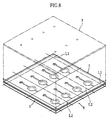
- the aggregate plate 5 comprises a plurality of base plate forming areas 50 comparted by virtual cutting lines L1, L2. Each base plate forming area 50 is formed with a path 20 including a reagent holding portion 22.
- the reagent holding portion 22 has a depth D1 of 50-200 ⁇ m and a volume of 0.05-5 ⁇ L, for example.
- the aggregate plate 5 may be made by molding a resin material. Alternatively, the aggregate plate 5 may be made by laser processing or etching with respect to a resin board.
- each reagent holding portion 22 of the aggregate plate 5 is provided with a reagent member 4.
- the reagent member 4 may be made by repeating a coating and drying procedure whereby material liquid is applied to the reagent holding portion 22 and then dried.
- the coating process of the material liquid is performed by an inkjet-type dispenser 6.
- the dispenser 6 is designed to dispense a droplet of 10-2000pL, for example.
- droplets 60 of the material liquid are dispensed from the dispenser 6 while the dispenser 6 is moved, so that a number of droplets 60 are applied to the bottom surface 22A of each reagent holding portion 22.
- this coating method for material liquid it is possible to apply the material liquid to a region that is apart from the side surfaces 22b of the reagent holding portion 22 by a constant distance (a region of the bottom surface 22A of the reagent holding portion 22 except a peripheral area) .
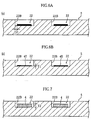
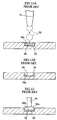
- Fig. 6A illustrates an example where the material liquid is applied on an area apart from the side surface 22B, where the distance D2 between the area to be coated with the material liquid and the side surface 22B is no smaller than 0.1 ⁇ m, for example.
- the drying of the material liquid may be performed by heating or air-blowing.
- the material liquid which is desirable to be dried within as short time as possible, can be dried within about 0.5-30 seconds by supplying heat energy, for example.
- the heat energy is supplied by applying radiant heat from above the sample liquid, for example.
- the radiant heat is applied by irradiating rays such as infrared rays or near-infrared rays, using an oscillator for oscillating infrared rays or near-infrared rays.
- a ray of wavelength different from infrared rays or near-infrared rays can be irradiated to apply radiant heat to the sample liquid.
- the heat energy can also be supplied by heat conduction from a heat source held in contact with the rear surface of the aggregate plate 5.
- the drying of the material liquid produces a thin layer 40 having a thickness T1 smaller than that of the applied material liquid, as shown in Fig. 6B, due to the evaporation of the moisture contained in the material liquid.
- the material liquid is prepared by dispersing a reagent in a solvent.
- concentration of the reagent in the material liquid is 0.1-60wt%, for example.
- Water is typically used as the solvent.
- An organic solvent may be used depending on the kinds of the reagents.
- the amount of the material liquid applied in each coating-drying process is 1-200nL, for example.
- the thin layer 40 having the thickness T1 of 0.1-5 ⁇ m is formed at each coating-drying process. As described above, such coating-drying process is performed an appropriate number of times, typically 2-200 times.
- the reagent member 4 is formed to a thickness T2 of 1-50 ⁇ m (see Fig. 7).
- a cover sheet 7 is adhered to the aggregate plate 5 to form an analytical tool collection 8. Thereafter, the analytical tool collection 8 is cut along the cutting lines L1, L2 to make individual analytical tools 1 shown in Figs. 1 and 2.
- the forming procedure of the reagent member is divided into a plurality of steps of applying and drying material liquids.
- the material liquid is dried quickly to form the thin layer 40 as shown in Fig. 6B, and finally the reagent member 4 is formed of laminated thin layers 40 as shown in Fig. 7.
- the thin layer 40 formed in each coating-drying process has a small thickness and thus has less irregularities in thickness. Accordingly, the resultant reagent member 4 also has less irregularities in thickness.
- the material liquid is applied to the reagent holding portion 22 at a portion apart from the side surfaces 22B (see Fig. 6A). In this way, as shown in Fig. 6B and 7, the material liquid is prevented from sticking to the side surfaces 22B in drying. As a result, the thin layer 40 has less irregularities in thickness, thereby reducing irregularities in thickness of the reagent member 4.
- the present embodiment is advantageous in utilizing the inkjet-type dispenser, which supplies a very small amount of droplet for applying the material liquid, so that the thin layer 40 is formed at the very small reagent holding portion 22 without contacting with the side surface 22B.
- the thickness irregularities of the reagent member 4 can be reduced, even when the reagent member 4 is very small.
- This advantage can be obtained without performing the conventional drying process of the material liquid where the material liquid is pressurized by a pressure rod.
- the reagent member 4 and hence the analytical tool 1 can be manufactured at advantageously low costs, since there is no cost for producing a pressure rod and no need to operate a pressure rod precisely.
- the production method according to the present invention is applicable not only to the production of the analytical tool 1 shown in Figs. 1 and 2, but also to other types of analytical tools provided with reagent members.
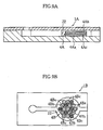
- Other typical examples to which the present invention is applicable are shown in Figs. 9A-9B, and Figs. 10A-10B, for example.
- the reagent member 4A has a stacking structure, at the reagent holding portion 22, which is composed of first and second reagent layers 4Aa, 4Ab containing different reagents, respectively.
- the second reagent layer 4Ab is laminated on the first reagent layer 4Aa via a water-soluble separation layer 4Ac.
- the separation layer 4Ac typically formed of CMC (carboxymethylcellulose), prevents the reagent of the first reagent layer 4Aa and the reagent of the second reagent layer 4Ab from blending before the sample is supplied to the reagent holding portion 22.
- the analytical tool 1A when the sample is supplied to the reagent holding portion 22, the reagent of the first reagent layer 4Aa, the reagent of the second reagent layer 4Ab and the sample react.
- a production method similar to the above-described method may be applied to the analytical tool 1A for forming the reagent layers 4Aa, 4Ab.
- the analytical tool 1B shown in Fig. 9B includes a reagent member 4B made up of several kinds of separate reagent members 4Ba, 4Bb, 4Bc (three kinds in the figure). In the figure, for convenience of illustration, the size of each reagent member 4Ba, 4Bb, 4Bc is significantly exaggerated. In the reagent holding portion 22, the reagent members 4Ba, 4Bb, 4Bc may overlap with each other.
- Such a reagent member 4B can be formed by applying and drying a material liquid including a first reagent, and then applying and drying a material liquid including a second reagent, and finally applying and drying a material liquid including a third reagent.
- the analytical tool 1C shown in Fig. 10A includes a plurality of reagent members 4Ca, 4Cb, 4Cc containing different reagents and being formed apart from each other in a plane.
- the analytical tool 1D shown in Fig. 10B is not formed with a recess (reagent holding portion), but provided with a plurality of reagent members 4D on a base plate whose surfaces are flat.
- a manufacturing method similar to the one described above may be employed to produce the reagent members 4Ca, 4Cb, 4Cc and 4D.
Landscapes
- Health & Medical Sciences (AREA)
- Chemical & Material Sciences (AREA)
- Analytical Chemistry (AREA)
- General Health & Medical Sciences (AREA)
- Hematology (AREA)
- Clinical Laboratory Science (AREA)
- Chemical Kinetics & Catalysis (AREA)
- Life Sciences & Earth Sciences (AREA)
- Engineering & Computer Science (AREA)
- Food Science & Technology (AREA)
- Investigating Or Analysing Biological Materials (AREA)
- Investigating Or Analyzing Non-Biological Materials By The Use Of Chemical Means (AREA)
- Sampling And Sample Adjustment (AREA)
- Analysing Materials By The Use Of Radiation (AREA)
- Investigating Or Analysing Materials By The Use Of Chemical Reactions (AREA)
Abstract
Description
Claims (19)
- A method of manufacturing an analytical tool, the method comprising a reagent member forming process for providing a base plate with a reagent member containing a reagent that reacts with a specific component contained in sample liquid,
wherein the reagent member forming process comprises a plurality of applying and drying steps in which material liquid containing the reagent is applied and then the material liquid is dried. - The method of manufacturing an analytical tool according to claim 1, wherein the plurality of applying and drying steps are performed with use of material liquid containing a same reagent.
- The method of manufacturing an analytical tool according to claim 1, wherein the plurality of applying and drying steps are performed 2-200 times.
- The method of manufacturing an analytical tool according to claim 1, wherein the material liquid contains 0.1-60wt% of the reagent.'
- The method of manufacturing an analytical tool according to claim 1, wherein the base plate comprises a reagent holding portion formed as a recess including a bottom surface and a side surface,
wherein the reagent member is formed in contact with the bottom surface. - The method of manufacturing an analytical tool according to claim 5, wherein the material liquid is applied to an area of the bottom surface spaced from the side surface by a constant distance.
- The method of manufacturing an analytical tool according to claim 6, wherein the distance between the side surface and the area applied with the material liquid is no smaller than 0.1µm.
- The method of manufacturing an analytical tool according to claim 5, wherein the reagent holding portion has a depth of 50-200µm.
- The method of manufacturing an analytical tool according to claim 5, wherein the recess has a volume of 0.05-5µL.
- The method of manufacturing an analytical tool according to claim 1, wherein the material liquid is applied with use of an inkjet-type dispenser.
- The method of manufacturing an analytical tool according to claim 10, wherein the dispenser is designed to dispense a droplet of 10-2000pL,
wherein the dispenser is used for applying the material liquid in a manner such that a plurality of droplets are attached to an application target portion. - The method of manufacturing an analytical tool according to claim 1, wherein an amount of the material liquid applied in each of the applying and drying steps is 1-200nL.
- The method of manufacturing an analytical tool according to claim 1, wherein the material liquid is dried by supply of heat energy.
- The method of manufacturing an analytical tool according to claim 13, wherein the supply of heat energy is performed by utilizing radiant heat applied from above the material liquid.
- The method of manufacturing an analytical tool according to claim 13, wherein the supply of heat energy is attained by holding a heat source in contact with a rear surface of the base plate.
- The method of manufacturing an analytical tool according to claim 1, wherein a thin layer having a thickness of 0.1-5.0µm is formed at each of the applying and drying steps,
wherein the reagent member is formed to have a thickness of 1.0-50.0µm upon completion of the reagent member forming process. - The method of manufacturing an analytical tool according to claim 1, wherein the reagent member is formed by a stack of a plurality of reagent layers containing different reagents.
- The method of manufacturing an analytical tool according to claim 1, wherein the reagent member comprises an assembly of separate reagent members containing different reagents.
- The method of manufacturing an analytical tool according to claim 1, wherein the analytical tool comprises a plurality of reagent members that contain different reagents and are spaced from each other in a plane.
Applications Claiming Priority (3)
| Application Number | Priority Date | Filing Date | Title |
|---|---|---|---|
| JP2002350197 | 2002-12-02 | ||
| JP2002350197A JP4253178B2 (en) | 2002-12-02 | 2002-12-02 | Method for manufacturing analytical tool |
| PCT/JP2003/015357 WO2004053480A1 (en) | 2002-12-02 | 2003-12-01 | Method for manufacturing tool for analysis |
Publications (3)
| Publication Number | Publication Date |
|---|---|
| EP1571446A1 true EP1571446A1 (en) | 2005-09-07 |
| EP1571446A4 EP1571446A4 (en) | 2006-02-22 |
| EP1571446B1 EP1571446B1 (en) | 2011-03-02 |
Family
ID=32500748
Family Applications (1)
| Application Number | Title | Priority Date | Filing Date |
|---|---|---|---|
| EP03812694A Expired - Lifetime EP1571446B1 (en) | 2002-12-02 | 2003-12-01 | Method for manufacturing tool for analysis |
Country Status (8)
| Country | Link |
|---|---|
| US (1) | US20060057740A1 (en) |
| EP (1) | EP1571446B1 (en) |
| JP (1) | JP4253178B2 (en) |
| CN (1) | CN1742199B (en) |
| AT (1) | ATE500500T1 (en) |
| AU (1) | AU2003302816A1 (en) |
| DE (1) | DE60336261D1 (en) |
| WO (1) | WO2004053480A1 (en) |
Cited By (1)
| Publication number | Priority date | Publication date | Assignee | Title |
|---|---|---|---|---|
| WO2010005467A2 (en) | 2008-07-09 | 2010-01-14 | Micropoint Bioscience Inc | Analytical cartridge with fluid flow control |
Families Citing this family (10)
| Publication number | Priority date | Publication date | Assignee | Title |
|---|---|---|---|---|
| WO2006137334A1 (en) * | 2005-06-23 | 2006-12-28 | Arkray, Inc. | Analytical implement |
| JP4721414B2 (en) * | 2005-08-15 | 2011-07-13 | キヤノン株式会社 | REACTION CARTRIDGE, REACTOR, AND METHOD FOR TRANSFERRING REACTION CARTRIDGE SOLUTION |
| JPWO2007052647A1 (en) * | 2005-11-01 | 2009-04-30 | パナソニック株式会社 | Sample solution analysis disk and mixed sample solution analysis method |
| JP2008128907A (en) * | 2006-11-22 | 2008-06-05 | Fujifilm Corp | Microchannel chip |
| JP5205922B2 (en) * | 2007-11-07 | 2013-06-05 | セイコーエプソン株式会社 | Biological material detection chip and method for manufacturing biological material detection chip |
| CN101623660B (en) * | 2008-07-09 | 2014-04-02 | 微点生物技术有限公司 | Analysis spraying canister having liquid stream control |
| WO2012001972A1 (en) * | 2010-06-30 | 2012-01-05 | 株式会社メタボスクリーン | Microchemical chip, method for producing same, and method for using same |
| JP5698085B2 (en) | 2010-07-12 | 2015-04-08 | アークレイ株式会社 | Biosensor and manufacturing method thereof |
| JP5545255B2 (en) * | 2011-03-31 | 2014-07-09 | 株式会社島津製作所 | Microchip and manufacturing method thereof |
| JP7206645B2 (en) * | 2018-06-08 | 2023-01-18 | 株式会社島津製作所 | Fluidic device manufacturing method and fluidic device |
Family Cites Families (35)
| Publication number | Priority date | Publication date | Assignee | Title |
|---|---|---|---|---|
| US4025669A (en) * | 1973-11-15 | 1977-05-24 | Owens-Illinois, Inc. | Multiple pass method of applying printing paste upon a substrate |
| US3975162A (en) * | 1974-03-13 | 1976-08-17 | Marine Colloids, Inc. | Applying reagent to medium and device therefor |
| CA1054034A (en) * | 1975-06-20 | 1979-05-08 | Barbara J. Bruschi | Multilayer analytical element |
| US4234316A (en) * | 1979-04-02 | 1980-11-18 | Fmc Corporation | Device for delivering measured quantities of reagents into assay medium |
| US4258000A (en) * | 1979-08-02 | 1981-03-24 | Obermayer Arthur S | Toxic-monitoring badge and method of use |
| US4387164A (en) * | 1980-11-05 | 1983-06-07 | Fmc Corporation | Method and apparatus for chemical analysis using reactive reagents dispersed in soluble film |
| US4753531A (en) * | 1983-11-29 | 1988-06-28 | Fuji Photo Film Co., Ltd. | Flat container type analytical instrument |
| US5178831A (en) * | 1986-10-08 | 1993-01-12 | Dai Nippon Insatsu Kab Ushiki Kaisha | Device for testing body fluids |
| US5047206A (en) * | 1987-03-11 | 1991-09-10 | Wayne State University | Reagent test strip |
| DE3902402C1 (en) * | 1989-01-27 | 1990-06-13 | Draegerwerk Ag, 2400 Luebeck, De | |
| JPH0331749A (en) * | 1989-06-29 | 1991-02-12 | Fuji Photo Film Co Ltd | Biochemical analysis apparatus and method for using this apparatus |
| US5212060A (en) * | 1990-04-27 | 1993-05-18 | Genesis Labs, Inc. | Dry test strip comprising a dextran barrier for excluding erythrocytes |
| DE4024544A1 (en) * | 1990-08-02 | 1992-02-06 | Boehringer Mannheim Gmbh | ANALYZING ELEMENT AND METHOD FOR THE PRODUCTION THEREOF |
| DE4303860C2 (en) * | 1993-02-10 | 1995-11-09 | Draegerwerk Ag | Carrier for colorimetric gas detection in composite film construction |
| JP3470973B2 (en) * | 1993-08-31 | 2003-11-25 | ロシュ ダイアグノスティックス コーポレーション | Reagents and their use |
| GB9405744D0 (en) * | 1994-03-23 | 1994-05-11 | Rolls Royce Plc | A multilayer erosion resistant coating and a method for its production |
| US5639428A (en) * | 1994-07-19 | 1997-06-17 | Becton Dickinson And Company | Method and apparatus for fully automated nucleic acid amplification, nucleic acid assay and immunoassay |
| CA2156226C (en) * | 1994-08-25 | 1999-02-23 | Takayuki Taguchi | Biological fluid analyzing device and method |
| JPH08247946A (en) * | 1995-03-14 | 1996-09-27 | Kdk Corp | Test piece used for reflectometer |
| EP0790861A1 (en) * | 1995-09-12 | 1997-08-27 | Becton, Dickinson and Company | Device and method for dna amplification and assay |
| US5916524A (en) * | 1997-07-23 | 1999-06-29 | Bio-Dot, Inc. | Dispensing apparatus having improved dynamic range |
| US6113855A (en) * | 1996-11-15 | 2000-09-05 | Biosite Diagnostics, Inc. | Devices comprising multiple capillarity inducing surfaces |
| EP1046912A1 (en) * | 1997-10-27 | 2000-10-25 | Idexx Laboratories, Inc. | Device and methods for determination of analyte in a solution |
| JP3350421B2 (en) * | 1997-11-06 | 2002-11-25 | 日立ソフトウエアエンジニアリング株式会社 | Biochip reader and biochip reading method |
| US6117396A (en) * | 1998-02-18 | 2000-09-12 | Orchid Biocomputer, Inc. | Device for delivering defined volumes |
| US6830934B1 (en) * | 1999-06-15 | 2004-12-14 | Lifescan, Inc. | Microdroplet dispensing for a medical diagnostic device |
| US6296811B1 (en) * | 1998-12-10 | 2001-10-02 | Aurora Biosciences Corporation | Fluid dispenser and dispensing methods |
| JP2000229245A (en) * | 1999-02-09 | 2000-08-22 | Seiko Epson Corp | Micro chemical reaction device |
| DE19923761C1 (en) * | 1999-05-21 | 2001-02-08 | Bruker Daltonik Gmbh | Processing of sample molecules of liquids, involves making the sample droplets stand or suspend from lyophilic or lyophobic anchors on flat support surfaces |
| US6696240B1 (en) * | 1999-10-26 | 2004-02-24 | Micronix, Inc. | Capillary test strip to separate particulates |
| US6420180B1 (en) * | 2000-01-26 | 2002-07-16 | Agilent Technologies, Inc. | Multiple pass deposition for chemical array fabrication |
| JP2002144555A (en) * | 2000-08-31 | 2002-05-21 | Riso Kagaku Corp | Ink jet printer and thick film printing method of the printer |
| JP2002340914A (en) * | 2001-03-14 | 2002-11-27 | Kawamura Inst Of Chem Res | Micronozzle, method for manufacturing the same, spotting method and spotter |
| JP2003133691A (en) * | 2001-10-22 | 2003-05-09 | Seiko Epson Corp | Film pattern forming method, film pattern forming apparatus, conductive film wiring, electro-optical device, electronic equipment, and non-contact card medium |
| US20030157503A1 (en) * | 2003-04-04 | 2003-08-21 | Mcgarry Mark W | Compositions and methods for performing biological reactions |
-
2002
- 2002-12-02 JP JP2002350197A patent/JP4253178B2/en not_active Expired - Lifetime
-
2003
- 2003-12-01 EP EP03812694A patent/EP1571446B1/en not_active Expired - Lifetime
- 2003-12-01 WO PCT/JP2003/015357 patent/WO2004053480A1/en not_active Ceased
- 2003-12-01 US US10/537,391 patent/US20060057740A1/en not_active Abandoned
- 2003-12-01 AU AU2003302816A patent/AU2003302816A1/en not_active Abandoned
- 2003-12-01 DE DE60336261T patent/DE60336261D1/en not_active Expired - Lifetime
- 2003-12-01 AT AT03812694T patent/ATE500500T1/en not_active IP Right Cessation
- 2003-12-01 CN CN2003801048741A patent/CN1742199B/en not_active Expired - Lifetime
Cited By (5)
| Publication number | Priority date | Publication date | Assignee | Title |
|---|---|---|---|---|
| WO2010005467A2 (en) | 2008-07-09 | 2010-01-14 | Micropoint Bioscience Inc | Analytical cartridge with fluid flow control |
| EP2304445A4 (en) * | 2008-07-09 | 2012-11-21 | Micropoint Bioscience Inc | ANALYTICAL CARTRIDGE WITH FLUID FLOW ADJUSTMENT |
| US8551422B2 (en) | 2008-07-09 | 2013-10-08 | Micropoint Bioscience, Inc. | Analytical cartridge with fluid flow control |
| US10001479B2 (en) | 2008-07-09 | 2018-06-19 | Micropoint Bioscience Inc. | Analytical cartridge with fluid flow control |
| US11181522B2 (en) | 2008-07-09 | 2021-11-23 | Micropoint Bioscience Inc. | Analytical cartridge with fluid flow control |
Also Published As
| Publication number | Publication date |
|---|---|
| CN1742199B (en) | 2012-06-13 |
| EP1571446A4 (en) | 2006-02-22 |
| EP1571446B1 (en) | 2011-03-02 |
| DE60336261D1 (en) | 2011-04-14 |
| ATE500500T1 (en) | 2011-03-15 |
| JP2004184180A (en) | 2004-07-02 |
| AU2003302816A1 (en) | 2004-06-30 |
| JP4253178B2 (en) | 2009-04-08 |
| CN1742199A (en) | 2006-03-01 |
| WO2004053480A1 (en) | 2004-06-24 |
| US20060057740A1 (en) | 2006-03-16 |
Similar Documents
| Publication | Publication Date | Title |
|---|---|---|
| EP1571446B1 (en) | Method for manufacturing tool for analysis | |
| US5605838A (en) | Method for the quantitative analysis of sample liquid | |
| JP3914806B2 (en) | Analysis chip | |
| CN1182600C (en) | Methods of Manufacturing Analyzers | |
| US9535028B2 (en) | Biosensors and methods of preparing same | |
| US8647589B2 (en) | Flow cell and method for manufacturing the same | |
| TWI641359B (en) | Test element for detecting at least one analyte in a body fluid | |
| WO2004046018A1 (en) | Micro fluid control device and process for producing the same | |
| JP2009128342A (en) | Microchip and its manufacturing method | |
| CN107199060A (en) | It is a kind of for three-dimensional electrofocusing's micro-fluidic chip of SPME and preparation method thereof | |
| US8129195B2 (en) | Method for the production of an analytical element | |
| US6121052A (en) | Reflectance sampler and method of use | |
| US8277761B2 (en) | Channelless fluidic sample transport medium | |
| EP1442854B1 (en) | Recycled lumber producing method | |
| JP4009683B2 (en) | Method for manufacturing analytical tool | |
| JP2004243193A (en) | Lab-on-a-chip, manufacturing method and device thereof | |
| JP4283512B2 (en) | Test tool and method of manufacturing the same | |
| EP4488691A1 (en) | Liquid sample analysis microchip and method for manufacturing same | |
| CA2542897A1 (en) | Optical cuvette with platform-and-well construction | |
| JP2009128341A (en) | Microchip and manufacturing method thereof | |
| HK1142296B (en) | Method for the production of an analytical element |
Legal Events
| Date | Code | Title | Description |
|---|---|---|---|
| PUAI | Public reference made under article 153(3) epc to a published international application that has entered the european phase |
Free format text: ORIGINAL CODE: 0009012 |
|
| 17P | Request for examination filed |
Effective date: 20050617 |
|
| AK | Designated contracting states |
Kind code of ref document: A1 Designated state(s): AT BE BG CH CY CZ DE DK EE ES FI FR GB GR HU IE IT LI LU MC NL PT RO SE SI SK TR |
|
| AX | Request for extension of the european patent |
Extension state: AL LT LV MK |
|
| A4 | Supplementary search report drawn up and despatched |
Effective date: 20060109 |
|
| RIC1 | Information provided on ipc code assigned before grant |
Ipc: G01N 31/22 20060101AFI20040629BHEP Ipc: B01J 19/00 20060101ALI20060102BHEP Ipc: G01N 37/00 20060101ALI20060102BHEP Ipc: B01L 3/00 20060101ALI20060102BHEP |
|
| DAX | Request for extension of the european patent (deleted) | ||
| 17Q | First examination report despatched |
Effective date: 20080917 |
|
| GRAP | Despatch of communication of intention to grant a patent |
Free format text: ORIGINAL CODE: EPIDOSNIGR1 |
|
| GRAS | Grant fee paid |
Free format text: ORIGINAL CODE: EPIDOSNIGR3 |
|
| GRAA | (expected) grant |
Free format text: ORIGINAL CODE: 0009210 |
|
| AK | Designated contracting states |
Kind code of ref document: B1 Designated state(s): AT BE BG CH CY CZ DE DK EE ES FI FR GB GR HU IE IT LI LU MC NL PT RO SE SI SK TR |
|
| REG | Reference to a national code |
Ref country code: GB Ref legal event code: FG4D |
|
| REG | Reference to a national code |
Ref country code: CH Ref legal event code: EP |
|
| REG | Reference to a national code |
Ref country code: IE Ref legal event code: FG4D |
|
| REF | Corresponds to: |
Ref document number: 60336261 Country of ref document: DE Date of ref document: 20110414 Kind code of ref document: P |
|
| REG | Reference to a national code |
Ref country code: DE Ref legal event code: R096 Ref document number: 60336261 Country of ref document: DE Effective date: 20110414 |
|
| REG | Reference to a national code |
Ref country code: NL Ref legal event code: VDEP Effective date: 20110302 |
|
| PG25 | Lapsed in a contracting state [announced via postgrant information from national office to epo] |
Ref country code: GR Free format text: LAPSE BECAUSE OF FAILURE TO SUBMIT A TRANSLATION OF THE DESCRIPTION OR TO PAY THE FEE WITHIN THE PRESCRIBED TIME-LIMIT Effective date: 20110603 Ref country code: SE Free format text: LAPSE BECAUSE OF FAILURE TO SUBMIT A TRANSLATION OF THE DESCRIPTION OR TO PAY THE FEE WITHIN THE PRESCRIBED TIME-LIMIT Effective date: 20110302 Ref country code: ES Free format text: LAPSE BECAUSE OF FAILURE TO SUBMIT A TRANSLATION OF THE DESCRIPTION OR TO PAY THE FEE WITHIN THE PRESCRIBED TIME-LIMIT Effective date: 20110613 |
|
| PG25 | Lapsed in a contracting state [announced via postgrant information from national office to epo] |
Ref country code: BG Free format text: LAPSE BECAUSE OF FAILURE TO SUBMIT A TRANSLATION OF THE DESCRIPTION OR TO PAY THE FEE WITHIN THE PRESCRIBED TIME-LIMIT Effective date: 20110602 Ref country code: AT Free format text: LAPSE BECAUSE OF FAILURE TO SUBMIT A TRANSLATION OF THE DESCRIPTION OR TO PAY THE FEE WITHIN THE PRESCRIBED TIME-LIMIT Effective date: 20110302 Ref country code: SI Free format text: LAPSE BECAUSE OF FAILURE TO SUBMIT A TRANSLATION OF THE DESCRIPTION OR TO PAY THE FEE WITHIN THE PRESCRIBED TIME-LIMIT Effective date: 20110302 Ref country code: NL Free format text: LAPSE BECAUSE OF FAILURE TO SUBMIT A TRANSLATION OF THE DESCRIPTION OR TO PAY THE FEE WITHIN THE PRESCRIBED TIME-LIMIT Effective date: 20110302 Ref country code: CY Free format text: LAPSE BECAUSE OF FAILURE TO SUBMIT A TRANSLATION OF THE DESCRIPTION OR TO PAY THE FEE WITHIN THE PRESCRIBED TIME-LIMIT Effective date: 20110302 Ref country code: FI Free format text: LAPSE BECAUSE OF FAILURE TO SUBMIT A TRANSLATION OF THE DESCRIPTION OR TO PAY THE FEE WITHIN THE PRESCRIBED TIME-LIMIT Effective date: 20110302 |
|
| PG25 | Lapsed in a contracting state [announced via postgrant information from national office to epo] |
Ref country code: BE Free format text: LAPSE BECAUSE OF FAILURE TO SUBMIT A TRANSLATION OF THE DESCRIPTION OR TO PAY THE FEE WITHIN THE PRESCRIBED TIME-LIMIT Effective date: 20110302 |
|
| PG25 | Lapsed in a contracting state [announced via postgrant information from national office to epo] |
Ref country code: EE Free format text: LAPSE BECAUSE OF FAILURE TO SUBMIT A TRANSLATION OF THE DESCRIPTION OR TO PAY THE FEE WITHIN THE PRESCRIBED TIME-LIMIT Effective date: 20110302 Ref country code: PT Free format text: LAPSE BECAUSE OF FAILURE TO SUBMIT A TRANSLATION OF THE DESCRIPTION OR TO PAY THE FEE WITHIN THE PRESCRIBED TIME-LIMIT Effective date: 20110704 |
|
| PG25 | Lapsed in a contracting state [announced via postgrant information from national office to epo] |
Ref country code: RO Free format text: LAPSE BECAUSE OF FAILURE TO SUBMIT A TRANSLATION OF THE DESCRIPTION OR TO PAY THE FEE WITHIN THE PRESCRIBED TIME-LIMIT Effective date: 20110302 Ref country code: SK Free format text: LAPSE BECAUSE OF FAILURE TO SUBMIT A TRANSLATION OF THE DESCRIPTION OR TO PAY THE FEE WITHIN THE PRESCRIBED TIME-LIMIT Effective date: 20110302 Ref country code: CZ Free format text: LAPSE BECAUSE OF FAILURE TO SUBMIT A TRANSLATION OF THE DESCRIPTION OR TO PAY THE FEE WITHIN THE PRESCRIBED TIME-LIMIT Effective date: 20110302 |
|
| PLBE | No opposition filed within time limit |
Free format text: ORIGINAL CODE: 0009261 |
|
| STAA | Information on the status of an ep patent application or granted ep patent |
Free format text: STATUS: NO OPPOSITION FILED WITHIN TIME LIMIT |
|
| 26N | No opposition filed |
Effective date: 20111205 |
|
| PG25 | Lapsed in a contracting state [announced via postgrant information from national office to epo] |
Ref country code: DK Free format text: LAPSE BECAUSE OF FAILURE TO SUBMIT A TRANSLATION OF THE DESCRIPTION OR TO PAY THE FEE WITHIN THE PRESCRIBED TIME-LIMIT Effective date: 20110302 |
|
| REG | Reference to a national code |
Ref country code: DE Ref legal event code: R097 Ref document number: 60336261 Country of ref document: DE Effective date: 20111205 |
|
| PG25 | Lapsed in a contracting state [announced via postgrant information from national office to epo] |
Ref country code: MC Free format text: LAPSE BECAUSE OF NON-PAYMENT OF DUE FEES Effective date: 20111231 |
|
| REG | Reference to a national code |
Ref country code: CH Ref legal event code: PL |
|
| REG | Reference to a national code |
Ref country code: IE Ref legal event code: MM4A |
|
| PG25 | Lapsed in a contracting state [announced via postgrant information from national office to epo] |
Ref country code: LI Free format text: LAPSE BECAUSE OF NON-PAYMENT OF DUE FEES Effective date: 20111231 Ref country code: IE Free format text: LAPSE BECAUSE OF NON-PAYMENT OF DUE FEES Effective date: 20111201 Ref country code: CH Free format text: LAPSE BECAUSE OF NON-PAYMENT OF DUE FEES Effective date: 20111231 |
|
| PG25 | Lapsed in a contracting state [announced via postgrant information from national office to epo] |
Ref country code: LU Free format text: LAPSE BECAUSE OF NON-PAYMENT OF DUE FEES Effective date: 20111201 |
|
| PG25 | Lapsed in a contracting state [announced via postgrant information from national office to epo] |
Ref country code: TR Free format text: LAPSE BECAUSE OF FAILURE TO SUBMIT A TRANSLATION OF THE DESCRIPTION OR TO PAY THE FEE WITHIN THE PRESCRIBED TIME-LIMIT Effective date: 20110302 |
|
| PG25 | Lapsed in a contracting state [announced via postgrant information from national office to epo] |
Ref country code: HU Free format text: LAPSE BECAUSE OF FAILURE TO SUBMIT A TRANSLATION OF THE DESCRIPTION OR TO PAY THE FEE WITHIN THE PRESCRIBED TIME-LIMIT Effective date: 20110302 |
|
| REG | Reference to a national code |
Ref country code: FR Ref legal event code: PLFP Year of fee payment: 13 |
|
| REG | Reference to a national code |
Ref country code: FR Ref legal event code: PLFP Year of fee payment: 14 |
|
| REG | Reference to a national code |
Ref country code: FR Ref legal event code: PLFP Year of fee payment: 15 |
|
| REG | Reference to a national code |
Ref country code: DE Ref legal event code: R082 Ref document number: 60336261 Country of ref document: DE Representative=s name: DEHNSGERMANY PARTNERSCHAFT VON PATENTANWAELTEN, DE |
|
| PGFP | Annual fee paid to national office [announced via postgrant information from national office to epo] |
Ref country code: GB Payment date: 20221222 Year of fee payment: 20 Ref country code: FR Payment date: 20221222 Year of fee payment: 20 Ref country code: DE Payment date: 20221213 Year of fee payment: 20 |
|
| PGFP | Annual fee paid to national office [announced via postgrant information from national office to epo] |
Ref country code: IT Payment date: 20221228 Year of fee payment: 20 |
|
| REG | Reference to a national code |
Ref country code: DE Ref legal event code: R071 Ref document number: 60336261 Country of ref document: DE |
|
| REG | Reference to a national code |
Ref country code: GB Ref legal event code: PE20 Expiry date: 20231130 |
|
| PG25 | Lapsed in a contracting state [announced via postgrant information from national office to epo] |
Ref country code: GB Free format text: LAPSE BECAUSE OF EXPIRATION OF PROTECTION Effective date: 20231130 |
|
| PG25 | Lapsed in a contracting state [announced via postgrant information from national office to epo] |
Ref country code: GB Free format text: LAPSE BECAUSE OF EXPIRATION OF PROTECTION Effective date: 20231130 |