EP1571422A2 - Method and apparatus for automatic remote utility meter reading, utility shut off and hazard warning and correction - Google Patents
Method and apparatus for automatic remote utility meter reading, utility shut off and hazard warning and correction Download PDFInfo
- Publication number
- EP1571422A2 EP1571422A2 EP05251234A EP05251234A EP1571422A2 EP 1571422 A2 EP1571422 A2 EP 1571422A2 EP 05251234 A EP05251234 A EP 05251234A EP 05251234 A EP05251234 A EP 05251234A EP 1571422 A2 EP1571422 A2 EP 1571422A2
- Authority
- EP
- European Patent Office
- Prior art keywords
- utility
- data
- usage
- gas
- utility usage
- Prior art date
- Legal status (The legal status is an assumption and is not a legal conclusion. Google has not performed a legal analysis and makes no representation as to the accuracy of the status listed.)
- Granted
Links
Images


Classifications
-
- G—PHYSICS
- G08—SIGNALLING
- G08B—SIGNALLING SYSTEMS, e.g. PERSONAL CALLING SYSTEMS; ORDER TELEGRAPHS; ALARM SYSTEMS
- G08B17/00—Fire alarms; Alarms responsive to explosion
- G08B17/06—Electric actuation of the alarm, e.g. using a thermally-operated switch
-
- G—PHYSICS
- G01—MEASURING; TESTING
- G01D—MEASURING NOT SPECIALLY ADAPTED FOR A SPECIFIC VARIABLE; ARRANGEMENTS FOR MEASURING TWO OR MORE VARIABLES NOT COVERED IN A SINGLE OTHER SUBCLASS; TARIFF METERING APPARATUS; MEASURING OR TESTING NOT OTHERWISE PROVIDED FOR
- G01D4/00—Tariff metering apparatus
- G01D4/002—Remote reading of utility meters
- G01D4/004—Remote reading of utility meters to a fixed location
-
- G—PHYSICS
- G08—SIGNALLING
- G08B—SIGNALLING SYSTEMS, e.g. PERSONAL CALLING SYSTEMS; ORDER TELEGRAPHS; ALARM SYSTEMS
- G08B25/00—Alarm systems in which the location of the alarm condition is signalled to a central station, e.g. fire or police telegraphic systems
-
- G—PHYSICS
- G08—SIGNALLING
- G08B—SIGNALLING SYSTEMS, e.g. PERSONAL CALLING SYSTEMS; ORDER TELEGRAPHS; ALARM SYSTEMS
- G08B25/00—Alarm systems in which the location of the alarm condition is signalled to a central station, e.g. fire or police telegraphic systems
- G08B25/002—Generating a prealarm to the central station
-
- Y—GENERAL TAGGING OF NEW TECHNOLOGICAL DEVELOPMENTS; GENERAL TAGGING OF CROSS-SECTIONAL TECHNOLOGIES SPANNING OVER SEVERAL SECTIONS OF THE IPC; TECHNICAL SUBJECTS COVERED BY FORMER USPC CROSS-REFERENCE ART COLLECTIONS [XRACs] AND DIGESTS
- Y02—TECHNOLOGIES OR APPLICATIONS FOR MITIGATION OR ADAPTATION AGAINST CLIMATE CHANGE
- Y02B—CLIMATE CHANGE MITIGATION TECHNOLOGIES RELATED TO BUILDINGS, e.g. HOUSING, HOUSE APPLIANCES OR RELATED END-USER APPLICATIONS
- Y02B90/00—Enabling technologies or technologies with a potential or indirect contribution to GHG emissions mitigation
- Y02B90/20—Smart grids as enabling technology in buildings sector
-
- Y—GENERAL TAGGING OF NEW TECHNOLOGICAL DEVELOPMENTS; GENERAL TAGGING OF CROSS-SECTIONAL TECHNOLOGIES SPANNING OVER SEVERAL SECTIONS OF THE IPC; TECHNICAL SUBJECTS COVERED BY FORMER USPC CROSS-REFERENCE ART COLLECTIONS [XRACs] AND DIGESTS
- Y04—INFORMATION OR COMMUNICATION TECHNOLOGIES HAVING AN IMPACT ON OTHER TECHNOLOGY AREAS
- Y04S—SYSTEMS INTEGRATING TECHNOLOGIES RELATED TO POWER NETWORK OPERATION, COMMUNICATION OR INFORMATION TECHNOLOGIES FOR IMPROVING THE ELECTRICAL POWER GENERATION, TRANSMISSION, DISTRIBUTION, MANAGEMENT OR USAGE, i.e. SMART GRIDS
- Y04S20/00—Management or operation of end-user stationary applications or the last stages of power distribution; Controlling, monitoring or operating thereof
- Y04S20/30—Smart metering, e.g. specially adapted for remote reading
Definitions
- This invention relates generally to the remote sensing art, and more specifically to apparatus for remote utility meter reading, including responses at the premises to fires, gas leaks, and other hazards, by sending alarms to utility companies, the fire department, and other emergency responders, and also emergency adjustment of electricity and gas connections.
- the present invention includes the capability of automatic activation of strategically placed fire extinguishers.
- electrical power since insulation burns and electrical shorts can create even more fire, the continued presence of live electrical power in the context of a fire can be dangerous, both as to adding more fire and, perhaps by inadvertent contact with the house wiring, to the firefighters that will be arriving to get the fire under control.
- the heat of a fire may break a gas line, and the release of such gas would undoubtedly increase the fire substantially, and even more dangerously may bring about an explosion.
- the present invention thus provides a method and apparatus by which either or both the electrical and gas services would be shut off automatically at the outbreak of a fire or occurrence of a gas leak, while at the same time providing remote notice both of the existence of the fire or gas leak and of the status of the electric and gas utility.
- Such an early warning would permit an earlier intervention in the fire or gas leak, so as to bring the particular circumstance under control and indeed to put out the fire or repair the gas leak, and the initial and dangerous step of turning off the electric power and gas in the midst of actual fire fighting would be avoided.
- a utility meter that measures either electrical power or gas consumption either has a dedicated telephone connected thereto or preferably the telephone is integral to the meter, but in either case also having a modem within or connected to the meter so that either upon command or on a predetermined schedule, preferably at off-peak hours, the telephone will dial the phone number of the responsible electrical power or gas companies and in some cases various emergency responders such as the fire department and transmit to that company or other entity a report of the current readings on the gas or electric meter, and other information as the situation may require.
- the meter preferably includes the ability to "break in” on any telephone call that was in process and carry out the various functions set out below.
- such services as "call waiting” and the like are preferably excluded from the line in order that its constant availability can be assured, and in a preferred embodiment a line is used that is dedicated entirely to use by the invention and has no other function.
- meter or a “meter/modem” will mean the same in either case, i.e., the meter itself, together with a modem and connection to a telephone line, either integrally within the meter or separately connected.
- telephone by itself will mean a connection from that modem to a line, i.e., an ordinary telephone line or by cable or other such means, including a meter antenna in the case of cellular phone transmission, through which a computer at the relevant utility company and the fire department can be contacted.
- the programming of a command schedule is carried out by a computer owned by the responsible utility company, or that programming could be carried out at the meter itself using installed programming means. Whether the programming is carried out at a remote computer or locally, that program will also include the periodic running of self-diagnostics both of the data transmission facilities and the operability of various sensors as a "backup" procedure for ensuring system reliability.
- a customer number or other such identification that has been assigned to the meter at a particular house or business, perhaps by way of the meter telephone number of the telephone attached thereto, or the address of the location at which the meter is installed, is registered in the computer at each relevant utility company so that the location of the meter from which a call has been received is immediately and automatically recorded.
- the total usage of electricity or gas is transmitted to the utility company computer, from which the usage over some preceding period, typically a month, can be calculated, and the billing for such usage can then be carried out, based on the identification of the customer using information previously stored in the computer that pertain to the phone number or address from which the call was made, or by other identifying information.
- the meter may instead or also have an incremental meter scale that will record only the usage over such preceding period, being reset to zero upon a scheduled reading, so that only the electricity or gas usage during that period would be sent to the company computer.
- the scheduling of meter readings, on a basis such as monthly, can also be done automatically by way of a clock, either the clock associated with the utility company computer or one contained within the meter. That clock could also be used to generate a command to read the meter at the time of startup or cutoff of service, or for similar such reasons.
- the utility company computer, as well as the on-site computer system, e.g. the microprocessor and associated memory and the like at the meter as will be described in more detail below, are entirely conventional in design, use conventional programming, data transmission and other procedures, and will be known to a person of ordinary skill in the art.
- the programming of the on-site device can be, and preferably is, carried out from the main utility company computer that also has complete access to the premises device in other respects.
- the company computer Upon receipt of a meter reading from a meter at some home or business, either of total or incremental usage, the company computer will transmit back a confirmation of such receipt, and reset to zero the incremental meter if that type of reading had been used. Upon the computer failing to receive any transmission in response to its command, or at the time that the transmission had been scheduled, that computer will first check as to whether or not it had properly sent its command or transmission schedule to the meter, and make whatever adjustments of the computer as may be necessary to accomplish a successful command or schedule transmission.
- the meter since transmission by the meter of the meter readings should result in the receipt by the meter telephone of the confirmation of receipt of the usage data by the company computer, and upon any failure to receive such confirmation, the meter would likewise carry out a predetermined number of attempts at such transmission, and the identification and repair of any equipment failure, or in some cases merely postpone the transmission if it were found that the problem was simply one of temporary noise on the lines.
- the electricity or gas meter is also connected to an appropriate "on/off" switch or valve that controls the electricity or gas, and in some cases would turn such utility on or off upon receipt of a command so to do from the remote utility computer.
- Manual operation of such controls is also provided, but the principal means of operation of the meter and related switching so as to cut off the electricity or gas derives from connection to alarms within the facility, whether a home or a business, warehouse, etc.
- the meter can also be activated locally, either manually or automatically by command from the alarm(s) installed within the house or business to which alarm(s) the meter/modem is also connected.
- manual activation is by way of an array of pre-programmed phone numbers, e.g., for the fire department, police, gas company, ambulance service, etc., that would be selected by the user based on the nature of the need.
- This feature would be an equivalent of a "911" call, except that the remote recipient of the call would be selected, and in the event the user was not able to converse, a pre-recorded message containing the identity of the caller and other relevant information would be sent to that call recipient.
- the same "outside" line can be used for the electricity and gas meters and various hazard detectors, selection among these being made by the telephone numbers that a microprocessor in the respective meters had been programmed to call, and by separate lines from sensors that will detect a fire or gas leak at appropriate locations in the home, office or other facility to those meter/modems, given that the gas and electric meters will often have different physical locations.
- provision would be made by which the automatic shutoff of the electricity could be locally overridden.
- notice of the fire only would be sent by the meter telephone to the fire station computer, wherein the fire station would have direct telephone connection through the meter telephone to the "on/off" switch or valve by which the electrical power and gas are controlled, so the fire fighter personnel could themselves decide whether or not to shut off either or both the electrical power or the gas, based either on their own knowledge of the particular situation at the indicated household or business or from their access to that same information in the remote computer. If not already done, fire department personnel would also send notice to the utility companies both of the fire and of any actions that the fire fighters might have taken in response to that fire, including shutting off either or both the electricity and/or the gas.
- a first embodiment of the invention includes data transmission system 10 shown in Fig. 1 that carries out first process 20 shown in the flow chart of Fig. 2, thus to transmit from meter/modem 12 through telephone line 14 to utility company computer 16 (e.g., an electric or a gas utility), the information listed in Fig. 3, which includes identification data for the meter, the current meter reading, and other relevant information, either listed as such or having memory space allocated therefor as indicated by the ellipsis at the bottom of Fig. 3.
- a remote recipient for hazard notices and the like, such as the fire department, is also represented by computer 16.
- the ellipsis at the bottom of Fig. 3 is intended to indicate that other information than that explicitly shown in Fig. 3 can also be included.
- Telephone line 14 can be of the ordinary type, or may be an optical "light pipe," a cable, cellular antenna or any other such means of communication, but since the data to be transmitted is to be in digital form, the line must be of a quality to carry such data, and meter/modem 12 and computer 16 must of course include a modem. Ensuing processes then occur as noted below so as to place data sent from the meter/modem 12 to computer 16 to be entered into computer 16, and computer 16 is correspondingly adapted to receive, store and act on such data, and send commands to meter/modem 12, all of which employs standard equipment and occurs in the ordinary manner as will be known to a person of ordinary skill in the art. In case of a power failure, Fig. 1 shows meter/modem 12 backed up by battery 18.
- computer 16 will draw on its historical data as held in memory therein to obtain the previous meter reading, and then calculate the amount of usage since that last meter reading, for purposes of billing. (By "current” reading is meant, of course, not electrical current, but rather the reading on the meter at the particular time.)
- the "Transmit Complete Data" box 28 is connected to "Extract Current Reading” box 26 for purposes of receiving not only that current meter reading but also all of the prior-listed data in Fig. 3.
- the "Usage for Period” entry in Fig. 3 could also be calculated within meter/modem 12 from the total usage reading, could be read directly by an incremental meter, could be calculated by computer 16 upon receipt thereto of the total usage data and then sent back to meter 12, or that "Usage for Period” could be deleted entirely, with the calculation of incremental usage data taking place only in company computer 16 as was previously described.
- meter/modem 12 With all equipment operating and the various steps being properly carried out, meter/modem 12 would have been at the "Await Confirmation” box 34 connected below “Transmit Complete Data” box 28 in the “Meter” sequence, the "Receive Complete Data” box 32 on the “Utility” side then connecting on a "Yes” line to "Send Confirmation” box 36 which in turn connects back to the "Receive Confirmation” box 38 in the "Meter” sequence, which in turn connects along another "Yes" line in the "Meter” sequence to the "End Call” box 40.
- Computer 16 would then have the data necessary to calculate out and otherwise administer a new billing to the customer indicated in the data sent by meter/modem 12. An operational error at any point in that course of events will bring forth alternative events that will now be described.
- the first external indication of an operational error would appear as a failure of computer 16 to receive the meter reading from meter/modem 12, although of course that failure may not lie in computer 16 itself but instead either in meter/modem 12 or line 14.
- Computer 16 has an ordinary screen display (not shown) onto which, in the event of such event, computer 16 will "post” a notice that an anticipated data reception had not been received, so that the utility company personnel will be made aware that an operational error has occurred hence the action indicated by "Repair” box 44 should be carried out.
- "Receive Confirmation" box 38 besides having a "Yes” line that ends the call at "End Call” box 38, also has a "No" line that extends to another "2 Min. Delay” box 46. From there another line extends upwardly and back to the "Transmit Complete Data” box 28, from which a second attempt at sending the data from meter/modem 12 to computer 16 is carried out. Although computer 16 may in fact have received the complete data but yet failed to notify meter/modem 12 of that fact, such retransmission of that data would indicate at computer 16 that the confirmation had either not been properly sent or at least had not been received at meter/modem 12, and that meter/modem 12 was still seeking such a confirmation.
- Repetition of the confirmation process at meter/modem 12 can be used to "trouble-shoot" the operation, since a case in which meter/modem 12 kept repeating the sending of data, but yet the data in computer 16 were found by examination to be new data actually received, the problem would then have been isolated to the confirmation process. It is important that confirmation be properly carried out, since that step is used not only to terminate a given transmission of data, but also, in the event that the data sent pertained not to total usage but to incremental usage, that confirmation must also "zero" that incremental meter for the next reading.
- metering mechanism 50 represents the device that actually measures either the usage of electrical power or the gas consumption, as attached to the lines carrying the electricity or gas.
- the structure and function of such meters is well known to a person of ordinary skill in the art and need not be discussed further, except to point out that the result of a reading, although often shown for view by a dial or the like on the meter itself, for reading by the human eye, must for present purposes also have been converted to digital form as in ordinary binary code, binary coded decimal (BCD) or the like, likewise in a manner that will be well known to a person of ordinary skill in that art.
- the data so recorded are transferred from metering mechanism 50 by microprocessor 52 into memory 54.
- microprocessor is meant here in a general sense and can, for example, include an Application Specific Integrated Circuit (ASIC), a “System on a Chip” (SoC), a Field Programmable Gate Array (FPGA) or the like, provided that provision is also made to carry out the functions to be described below, and providing further that preferably microprocessor 52 includes a crystal clock 56 or the like for purposes of defining a time schedule (e.g., monthly) of meter readings. Battery 59 provides backup power in the event of a power failure to the microprocessor 52, memory 54, clock 56 and modem 58. Microprocessor 52 is further programmed to transmit notice to the electric utility computer 16 (Fig. 1) of a power failure.
- ASIC Application Specific Integrated Circuit
- SoC System on a Chip
- FPGA Field Programmable Gate Array
- Fireboy® and of Quincy, MA both (1) an automatic fire extinguisher in its HFC-227ea model that uses heptafluoropropane as the smothering agent, and discharge is initiated at 175° F; and (2) an automatic engine shutoff/override system in their series 3000, 5000 and 8000 series systems, both of which devices are deemed to be applicable to and operable in the system of hazard protection set out herein as concerns fires.
- This particular Fireboy® fire extinguisher can be operated manually as well as automatically, and such manual operation can easily be modified to be operable remotely under the control of microprocessor 52 under a programming process such as that of Schultz et al. '151, since the tire pressure sensor noted in that patent is operable by a microprocessor (Col. 4, lines 16 - 17).
- a microprocessor An example of such a microprocessor is given in Schultz et al. '151 as the HMOS-E single component 8-bit microcomputer 8748H from Intel (Col. 4, lines 63 - 65), and specific examples of other components are also set forth that would be under the remote control of microprocessor 52 under a programming process such as that of Schultz et al.
- IR emitters Model No. LD271 from Seimens-Litronix (Col. 5, lines 13 - 14), photo transistor No. Model BP103-B from Seimens-Litronix (Col. 5 lines 28, 29), comparator Model No. LM339 from National Semiconductor (Col. 5, lines 41 - 42), a BCD-to-7 segment latch/decoder Model No. MC54/74H4511 from Motorola (Col. 5, lines 59 - 60), segment display Model. No. FNF500 from Fairchild Semiconductor (Col. 5, lines 64 - 65), tone decoder Model No. LM567 also from Fairchild Semiconductor (Col. 6, lines 49 - 51), pressure sensor Model No.
- the Shultz et al. infrared receiver can receive signals at distances of approximately 3 - 5 feet (Col. 23, lines 38 - 41) from the sensor, which could be installed to read water pressure in lines to a water sprinkler system, and hence could be used in the present invention to detect the turning on of a water sprinkler in lieu of the "moisture detector,” humidity meter, or oximeter adaptations as discussed further below.
- a CPU based system as is well known in the art comprises: a control circuit for maintaining the proper sequence of events with regard to interrupts, instructions, wait requests, and timing functions, an arithmetic logic unit (ALU) for performing arithmetic and logic operations, and various registers for program counting, an instruction decoder, and addressing unit.”
- ALU arithmetic logic unit
- registers for program counting, an instruction decoder, and addressing unit.
- modem 58 Upon command from computer 16 in accordance with a pre-programmed schedule, by manual intervention, or in response to an emergency situation as will be described below, modem 58 will be provided with the current reading as stored in memory 54, together with the other data listed in Fig. 3 as shown in the "Extract Current Reading” box 26 in Fig. 2, and then transmit the entirety of that data to computer 16 in accordance with the "Transmit Complete Data” box 28 of Fig. 2. Modem 58 will of course be configured to dial the proper utility company telephone number for the modem that serves as an input port to computer 16. The other activities outlined in Fig. 2 will of course proceed as before, the present description being intended only to provide more detail as to the functioning of whatever modem may be in use.
- Figure 5 now shows a second embodiment of the invention wherein two or more utility companies are configured to receive meter readings.
- Both first metering mechanism 60 and second metering mechanism 62 are seen to collect usage data from respective first and second lines (which respectively could be electricity and gas lines, or both could be gas lines or both electric lines), whereupon microprocessor 64 and clock 66 then cause the data so received to be sent to memory 68.
- first and second lines which respectively could be electricity and gas lines, or both could be gas lines or both electric lines
- microprocessor 64 and clock 66 then cause the data so received to be sent to memory 68.
- Those data will of course be stored and otherwise treated as separate and distinguishable entries into memory 68.
- memory 68 will have had stored therewithin the respective phone numbers of the computers at the two utilities, if two are involved, so that the usage data recorded by first and second metering mechanisms 60, 62 will be sent by modem 70 to the proper utility, i.e., to first utility 72 and second utility 74, respectively.
- the procedures set out in Fig. 2, adapted to serve two or utility companies, will of course proceed as before.
- the two ellipses 76 shown (vertically) on respective sides of microprocessor 64 and clock 66 are intended to show that additional power usage data from other meters could be gathered and transmitted to the proper utility companies. Such a procedure need not involve any more utility companies, but could instead involve a number of different meter readings from different meters that would be sent to a single utility. This could be the case, e.g., in an apartment building in which the several apartments were individually metered for electricity usage.
- Battery 78 in Fig. 5 provides backup power in the event of a power failure to microprocessor 64, clock 66, memory 68, and modem 70.
- Microprocessor 64 is further programmed to transmit notice to the electric utility computer 16 (Fig. 1) of any such power failure, i.e., the discontinuance of any use of electricity.
- microprocessor 64 be programmed to show as well any surge of power usage beyond that, say, of the startup of an electric motor, such as to show a level of current flow that would indicate a short circuit.
- a warning if heeded by identifying and eliminating the source of such a short circuit, might indeed forestall the development of a fire, or perhaps at least "catch it" before it has reached a point of a fire that would set off the alarm.
- the metering mechanism would be taking readings continually in any event, and it would be well within the knowledge of a person of ordinary skill in the art to program into microprocessor 52 in Fig. 4 or microprocessor 64 in Fig.
- an important additional function of the invention lies in providing notice to both the fire company and the (respective) utility company(ies) of the outbreak of a fire, or of a gas leak, at a home or at other buildings.
- the occurrence of a fire or gas leak, or even a power failure or sudden electrical current surge, would constitute a "hazard" in the premises itself as opposed to an operational error in the system described above that reports on the normal course of events.
- one or more fire alarms and/or gas detectors are also connected to the utility usage meter, whereby to send notice that a fire or a gas leak has occurred, but further in the electrical system to record the current being drawn, which could fall to zero or be excessive.
- Figure 6 thus shows an embodiment of the invention that for purposes of simplicity will treat only a single utility, but may be applied to several utilities and/or companies in the manner of Fig. 5, and in addition to the routine provision of utility usage data will also send notice, upon such event occurring, that a fire has broken out, a gas leak has been detected, or there is an abnormal draw of electrical current at the premises - or again, preferably all of those functions can be employed.
- a burglar alarm system can also be connected to meter/modem 58, 70, or 72 for like purposes, in which case the microprocessor 52, 64 would need to be programmed accordingly, including provision in meter/modem 58, 70, or 82, for calling the police and/or a private security company.
- Such usage could employ a motion detector such as that described by U. S. Patent No. 6,650,242 issued Nov. 18, 2003, to Clerk et al.
- This patent relates directly to providing warnings in a warehouse or the like of the movement of vehicles or people relative to injury hazards, using a rotatable infrared (IR) fan beam derived from light emitting diodes (LEDs) directed from a mobile vehicle to warn of the approach thereof, but would equally apply to having that fan beam emission at a fixed site to warn of the approach of a person.
- IR infrared
- LEDs light emitting diodes
- '242 itself is by way of an IR detector device worn either by company personnel or placed at strategic plant locations that will respond with an audible or visible warning upon coming into contact with the IR beam from the vehicle as that vehicle approaches, but it could be possible to mount the detector near the IR source and rely on reflection from a person approaching to detect that person's presence, or of course other motion detector devices might be employed instead.
- hazards In such a fixed site situation, connection would be made to meter/modem 12 as in the other cases described.
- the present invention provides not only the recording and reporting of utility usage data, but is broad enough in design to encompass the wide range of additional hazard warning functions as described herein.
- microprocessor 64 is programmed to store within memory 68, which may be a hard drive, for example, a permanent record both of utility usage data and any fire, gas leak, or other hazard events and the like for accounting, administrative, insurance, legal, or other purposes.
- memory 68 may be a hard drive, for example, a permanent record both of utility usage data and any fire, gas leak, or other hazard events and the like for accounting, administrative, insurance, legal, or other purposes.
- microprocessor 64 Among the events automatically reported on, for which operations the necessary programming within microprocessor 64 is provided, are included the occurrence of any extremes in the usage of either or both electrical power and gas.
- Zero electrical power usage i.e., a "power failure”
- excessive electrical power usage can mean the occurrence of a "short" from which may come the outbreak of a fire.
- the Thermo Electron Corporation provides an FX-IR Single Gas Transmitter, Model 67-0022-1, that detects gas at the "trace" level and can be adapted for the detection of a gas leak in a manner appropriate to this particular remote warning context. That is, this instrument operates on 3-phase power, possibly providing analog data with a response time of 12 seconds, and hence, in that case, microprocessor 64, for example, must be provided with an analog-to-digital converter ("A/D" or "ADC”) in order to provide a reading that will generate a warning signal from microprocessor 64.
- A/D analog-to-digital converter
- That feature of proving digital data is in fact an option available to the hazard detector, and since the addition of a switch or relay to the detector is also an option, this detector can also, and preferably will, be used to turn off the gas supply upon the occurrence of a gas leak, provided that the gas line itself has been provided with a valve that is operable by such a switch or relay.
- a valve that provided by OMEGA Engineering, Inc., in its model SV-300 supplied under the name "OMEGA-FLOTM 2-Way General Purpose,” which is manually set but can then be "tripped" (i.e., closed) electrically, as would occur upon receiving a signal so to do from the aforesaid gas leak detector.
- CCI Controls provides a gas leak detector that incorporates either an alarm only facility in its model 7773, or both the alarm and valve shutoff of the gas supply in its model 7239, and up to three such units can be interconnected so as to operate in tandem on a single output line.
- the valve sizes range from 3/8 inch to one inch, and hence can be used in either a household or an industrial context. Included in these instruments is the facility to analyze the ambient weather and seasonal weather conditions so as to adjust the sensor threshold point in order to avoid “false alarms.” Once the gas supply is turned off at the valve, that gas will remain off until manually turned back on.
- These detectors also have a battery backup in the event of an electrical power failure.
- Fig. 6 shows in block diagram form a simplified version of such an arrangement
- Fig. 7 is a flow chart that demonstrates the procedures carried out by the apparatus of Fig. 6.
- the apparatus is similar to that shown in Fig. 1, but with the addition of connections either or both to a fire alarm device and a gas leak detector, or to other such hazard detectors. That is, meter/alarm system 80 of Fig.
- meter/modem 82 is seen to include the usual meter/modem 82, a telephone line (which as noted earlier could be a cable, a cellular antenna, etc.), and utility company computer 86, but now with the addition of alarm 88 that upon responding, say, to smoke as with a smoke alarm, or the detection of a gas leak, would transmit a "fire” or "gas leak” signal to meter/modem 82.
- the manner that is used by meter/modem 82 to receive an alarm signal of any type can be direct and automatic, wherein alarm 88 sends a signal to meter/modem 82 immediately upon detection of a hazard, or meter/modem 82 can periodically query alarm 88 for the presence of an alarm indication, the former method being preferred.
- hazard detector 90 that may detect smoke, a gas leak, etc., that connects to alarm 88.
- hazard detector 90 that may detect smoke, a gas leak, etc., that connects to alarm 88.
- the "hazard" detected would not be the fire as such but rather the fact that the water sprinkler system had been turned on to spray water because of a local fire, as noted below.
- Fig. 6 Also shown in Fig. 6 is a line from "Alarm" box 88 to "Power" box 92, at which the utility in question can be shut off as will be described further below.
- notification of a fire can arise not only from an ordinary smoke detector, typically of an electronic type, but also by the activation of a water sprinkler system, if appropriate detectors are provided at a sprinkler outlet that water has begun to course therefrom.
- a detector might possibly be provided, for example, by adaptation of the "moisture detector” described in U. S. Patent No. 4,377,783 issued Mar. 22, 1983, to Wagner, which patent is by this reference incorporated herein in its entirety as though fully set forth.
- An ordinary humidity detector would serve the same purpose, one example of such a humidity probe being the HUMICAP® thin-film polymer sensor offered by the Vaisala Group of Vantaa, Finland.
- the Silent Knight company of Maple Grove, MN provides its SK-5208 Fire Alarm Control Communicator that is specifically adapted to control water sprinkler systems as installed in manufacturing plants, warehouses, schools, and the like, and also provides its SK-5235 Remote Annunciator that allows remote programming along with other accessories.
- the device would need to include means for recognizing a hazard, e.g., by including means for entering a predefined threshold value, the later measurement of which would be taken to be an indication of a reportable hazard, and such alarm would then be sent to meter/modem 82 immediately upon detection of a hazard, and meter/modem 82 would then carry out the several processes as have previously been described.
- the alarm device be it a smoke detector, a sprinkler system, a gas leak detector, humidity or moisture detector or the like
- appropriate indicator means by which a query sent to it by meter/modem 82 would yield a measurement response, or such device on its own volition, will provide different indications depending upon whether or not the sensor device has responded to the occurrence of whatever stimulus to which the device was designed to respond.
- the one could be a smoke detector, as noted above, or a water sprinkler system would include a sensor that would detect the ejection of water from a sprinkler such as that just noted, and the same procedure would apply to a gas leak detector.
- FIG. 7 The rightward part of Figure 7 is essentially a duplicate of Fig. 2, and indeed retains the same reference numerals, but has had added thereto the steps involved in responding to an alarm in accordance with Fig. 6. That is, the right side of Fig. 7 includes everything in the flow diagram shown in Fig. 2, but with alarm system 100 now shown on the left side of Fig. 7.
- the normal operations as previously described with reference to Fig. 2 will be carried out as before, independently of the operations of the attached alarm system 100. Consequently, no further description of the first process 20 of Fig. 2 and now shown again in Fig. 7 is necessary here, and only alarm system 100 will be described, but to include the fact that the processes of alarm system 100 may serve also to terminate those of Fig. 2 as shown on the right side of Fig. 7 - continued readings of meter/modem 82 in Fig. 6 would clearly be inapplicable if alarm system 100 had turned off the utility - and hence the two processes are shown to be linked.
- meter/modem 82 automatically receives "status reports" from the alarm system will now be described, commencing with the "Signal From Alarm” box 102.
- the arrow that connects alarm box 88 to meter/modem 82 is bidirectional, meaning that queries can be sent from meter/modem 82 to alarm box 88, which in turn can send a response back to meter/modem 82, either in response to a query or on its own volition.
- the system can be programmed to send a query to alarm box 88 only on initial startup, the processes shown on the left side of Fig.
- alarm box 88 can be "self-starting" and then automatic so that no queries at all were used; or at the other extreme repetitive queries from meter/modem 82 to alarm 88 might be used.
- the "Signal From Alarm" box 102 in Fig. 7 is bidirectional with respect to its connection to the "Send Command" box 22 of Fig. 7 for the same reason. It should be emphasized that all of first process 20 continues as before, with first process 20 being carried out in the apparatus of Fig. 6, while at the same time the alarm process 100 shown to the left in Fig. 7 likewise proceeds, also using the apparatus of Fig. 6, and quite independently of first process 20 that is taking place on the right side of Fig. 7 (other than to terminate the first process 20 in the event the utility referred to is turned off by second process 100).
- Fig. 4 The devices shown in Fig. 4 are taken here to represent as well the structure that is applicable to meter/modem 82 of Fig. 6 and hence to the operations shown in Fig. 7. At the same time, the operations of Fig. 7 also depend on the elements of Fig. 6, especially alarm 88.
- "Send Command" box 22 is initiating process 20 because of having received either an internal, timed command from microprocessor 52 of Fig. 4 so to transmit that had been programmed within microprocessor 52 or had received a command from the utility company computer 16
- microprocessor 52 of Fig. 4 has also sent a query to alarm 88 of Fig. 6 as to whether or not alarm 88 has detected a fire or gas leak. That query step is shown by the leftward pointing arrow head of Fig.
- That short delay is to determine whether or not that first alarm might have been a "false alarm,” that would be shown by there being no repetition of that alarm in the second "Signal from Alarm?" box 104 that connects to the bottom of "45 Sec. Delay” box 104. If there is no such second alarm, the "No" line extending from second "Signal from Alarm?" box 104 back up to first "Signal from Alarm?" box 102 then continues the routine monitoring for an alarm. A "Yes" response in second "Signal from Alarm?" box 104, however, indicates that the first such alarm was not a false alarm, and hence a hazard reporting sequence is commenced. That 45 second delay could of course be set by microprocessor 52 of Fig.
- the fire department is called first, through the programming of microprocessor 52 of Fig. 4, and at the same time the electrical power is shut off by that same programming, as indicated by the branch line of that "Yes" line that extends down to "Shut Off Electricity” box 110.
- the connection required to cause that shut down is shown by the line that extends from “Alarm” box 88 down to "Power” box 92, wherein by “Power” is generally meant either the electrical power or the gas supply.
- the third priority of action following the detection of a gas leak is shown by "Notify Fire Department of Gas Leak" box 120, for the purpose of warning that facility that there may be an impending disaster at the premises, although nothing had yet occurred, and the fire department could then respond as deemed appropriate.
- Asterisks 122 in Fig. 7 are intended to show, as was shown by ellipses 76 in Fig. 5, that additional utilities, whether electric or gas, can also be accepted by the system described with proper programming of microprocessor 52.
Landscapes
- Physics & Mathematics (AREA)
- General Physics & Mathematics (AREA)
- Business, Economics & Management (AREA)
- Emergency Management (AREA)
- Arrangements For Transmission Of Measured Signals (AREA)
- Alarm Systems (AREA)
- Radar Systems Or Details Thereof (AREA)
- Selective Calling Equipment (AREA)
Abstract
Description
the status of the electric and gas utility. Such an early warning would permit an earlier intervention in the fire or gas leak, so as to bring the particular circumstance under control and indeed to put out the fire or repair the gas leak, and the initial and dangerous step of turning off the electric power and gas in the midst of actual fire fighting would be avoided. It would also be appropriate for the respective utility companies to provide, to the owner of the home or other building, instructions that announce the presence of this shutoff capability, actions with respect to such facilities that such owner either should take or would not be allowed to take, and the circumstances under which the equipment would be used, as part of the service contract.
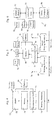
In the drawings:
- Figure 1
- is a block diagram of a system from the prior art having a meter/modem unit that encompasses just the meter reading function as to a single utility.
- Figure 2
- is a flow chart that outlines a first implementation of the invention shown in Fig. 1 involving only the meter reading aspect of either an electric or a gas utility.
- Figure 3
- indicates from the prior art an example of the kind of information to be transmitted between the meter and the utility company.
- Figure 4
- is a more detailed block diagram of the meter/modem unit of Fig. 1 that includes aspects of the invention.
- Figure 5
- is a block diagram of an alternative embodiment of the meter/modem of Fig. 4, including the addition of one or more metering mechanisms and corresponding means for transmitting data to the relevant utility company.
- Figure 6
- is a block diagram of a second aspect of the invention that includes
giving notice of the outbreak of a fire or gas leak at the premises,
and - Figure 7
- is a flow chart outlining the functioning of the apparatus of Fig. 6 as to two or more different or similar utilities.
Claims (44)
- Utility monitoring apparatus comprising:utility usage metering means;utility usage reporting means;utility hazard detection means; andutility hazard reporting means.
- The apparatus of claim 30 wherein said utility comprises electrical power.
- The apparatus of claim 30 wherein said utility comprises natural gas and said hazard further comprises other dangerous gases and liquids.
- The apparatus of claim 30 wherein said hazard detection means comprises a fire alarm.
- The apparatus of claim 4 further comprising means for transmitting a report to one or more remote recipients the fact that a fire has occurred at a premises at which said utility monitoring means is located.
- The apparatus of claim 5 wherein said apparatus automatically transmits a report to one or more remote recipients the fact that a fire has occurred at a premises at which said utility monitoring means is located.
- The apparatus of claim 3 wherein said hazard detection means comprises a gas leak detector.
- The apparatus of claim 7 further comprising means for transmitting a report to one or more remote recipients the fact that a gas leak has occurred at a premises at which said utility monitoring means is located.
- The apparatus of claim 8 wherein said apparatus automatically transmits a report to one or more remote recipients the fact that a gas leak has been detected at a premises at which said utility monitoring means is located.
- The apparatus of claim 30 wherein said hazard detection means comprises electrical current monitoring means.
- The apparatus of claim 10 wherein said electrical current monitoring means further comprises means for detecting zero electrical current and means for transmitting notice of said zero electrical current to an electrical utility company.
- The apparatus of claim 11 wherein said apparatus automatically transmits notice of said zero electrical current to an electrical utility company.
- The apparatus of claim 10 wherein said electrical current monitoring means further comprises means for detecting excessive electrical current and means for transmitting notice of said excessive electrical current to an electrical utility company.
- The apparatus of claim 13 wherein said apparatus automatically transmits notice of said excessive electrical current to an electrical utility company.
- The apparatus of claim 3 wherein said utility usage metering means and utility usage reporting means further comprise means for reporting zero gas usage upon the occurrence of zero gas usage.
- The apparatus of claim 3 wherein said utility usage metering means and utility usage reporting means further comprise automatic means for reporting zero gas usage upon the occurrence of zero gas usage.
- The apparatus of claim 30 wherein said utility usage and utility hazard reporting means comprise sensor means, data collection means, data transmission means, data reception means, data processing means, error detection means, and error correction means.
- The apparatus of claim 17 wherein said error detection means further comprises means for sending confirmation data from said data reception means to said data collection means confirming that utility usage data from said data collection means had been successfully reported to said data reception means.
- The apparatus of claim 17 wherein said error resolution means further comprises means for repetitive use of said error detection means a predetermined number of times, followed by identification and repair of any malfunction in the operation of said sensor means, data collection means, data transmission means, data reception means, and data processing means.
- A method of reporting utility usage comprising:providing utility usage monitoring means to establish utility usage data;providing utility usage data processing means;providing means for transmitting said utility usage data from said utility usage data processing means to a remote data receiving apparatus;providing access means to said means for transmitting said utility usage data in the event said means for transmitting said utility usage data is found to be in use;transmitting confirmation from said data receiving apparatus to said utility usage processing means of the reception of said utility usage data; andrepeating said transmission of said utility usage data to said data receiving apparatus a predetermined number of times in the event said confirmation is not received by said utility usage processing means; and in the event said transmission of said utility usage data to said data receiving apparatus is not thereby successful, initiating the identification and repair of any malfunction in said utility usage monitoring means, utility usage data processing means, andsaid means for transmitting said utility usage data from said utility usage data processing means to a remote data receiving apparatus.
- The method of claim 20 wherein said access means comprises providing a bypass line and switching means therefor by which a telephone line to which said means for transmitting said utility usage data is connected can be disconnected, andupon a finding that said outside line to a utility company was being otherwise used.a) disconnecting with said switching means said telephone line from connection thereof to an outside line to a utility company, andb) connecting with said switching means said bypass line to said outside line to a utility company
- The method of claim 20 wherein said utility usage data processing means comprises programmable microprocessor means and memory, anda) programming said microprocessor means to receive and store utility usage data;b) storing in said memory the telephone numbers of computers of those utility companies whose services are being utilized;c) storing in said memory said utility usage data; andd) transmitting said utility usage data to that selected one of said those utility companies whose services are being utilized that had provided the utility for which said utility usage data had been utilized.
- The apparatus of claim 30 further comprising hazard correction means.
- The apparatus of claim 23 wherein said hazard correction means comprises fire suppressant means and the automatic activation of said fire suppressant means upon the detection of a fire.
- The apparatus of claim 23 wherein said hazard correction means comprises gas shutoff means and the automatic activation of said gas shutoff means upon the detection of a gas leak.
- The apparatus of claim 30 further comprising self-diagnostic means adapted to test and report on the operational capability of said utility usage metering means, utility usage reporting means, utility hazard detection means, and utility hazard reporting means at the time of any such test.
- The apparatus of claim 30 further comprising means for turning off and on from a remote source the provision of electrical power at a premises receiving said electrical power.
- The apparatus of claim 30 further comprising means for turning off and on from a remote source the provision of gas at a premises receiving said gas.
- The apparatus of claim 16 wherein said utility usage metering means and utility usage reporting means further comprises automatic means for reporting excessive gas usage upon the occurrence of excessive gas usage.
- The apparatus of claim 1 further comprising data recording means adapted to receive digital data, wherein said digital data may be provided from either or both of said utility usage metering means and/or said utility hazard detection means, and placing into digital memory a record of said digital data as obtained from using either or both of said utility usage metering means and/or said utility hazard detection means.
- The apparatus of claim 30 wherein said hazard detection means further comprise burglar alarm means.
- The apparatus of claim 17 wherein said utility hazard detection means comprises water sprinkler means adapted to detect and report the turning on of a water sprinkler system.
- The apparatus of claim 32 wherein said water sprinkler means comprises water sprinkler detection means and water sprinkler reporting means.
- The apparatus of claim 32 wherein said water sprinkler detection means comprises sensor means.
- The apparatus of claim 32 wherein said water sprinkler detection means comprises data collection means.
- The apparatus of claim 32 wherein said water sprinkler reporting means comprises data transmission means.
- The apparatus of claim 32 wherein said water sprinkler reporting means comprises data reception means.
- The apparatus of claim 32 wherein said water sprinkler reporting means comprises data processing means.
- The apparatus of claim 32 wherein said water sprinkler detection means comprises error detection means.
- The apparatus of claim 32 wherein said water sprinkler detection means comprises error correction means.
- The apparatus of claim 6 wherein following a predetermined delay said apparatus will automatically recheck to determine whether said alarm has continued to generate a report, and if not will foreclose the transmittal of said report as first generated.
- The apparatus of claim 9 wherein following a predetermined delay said apparatus will automatically recheck to determine whether said alarm has continued to generate a report, and if not will foreclose the transmittal of said report as first generated.
- The apparatus of claim 5 wherein, at the time of sending said report that a fire had occurred, a second action taken is to shut off the electrical power in the premises.
- The apparatus of claim 5 wherein, at the time of sending said report that a fire had occurred, a second action taken is to shut off the natural gas in the premises.
Applications Claiming Priority (2)
| Application Number | Priority Date | Filing Date | Title |
|---|---|---|---|
| US792482 | 1991-11-15 | ||
| US10/792,482 US7088239B2 (en) | 2004-03-02 | 2004-03-02 | Method and apparatus for all-purpose, automatic remote utility meter reading, utility shut off, and hazard warning and correction |
Publications (3)
| Publication Number | Publication Date |
|---|---|
| EP1571422A2 true EP1571422A2 (en) | 2005-09-07 |
| EP1571422A3 EP1571422A3 (en) | 2005-12-14 |
| EP1571422B1 EP1571422B1 (en) | 2007-06-13 |
Family
ID=34750604
Family Applications (1)
| Application Number | Title | Priority Date | Filing Date |
|---|---|---|---|
| EP05251234A Expired - Lifetime EP1571422B1 (en) | 2004-03-02 | 2005-03-02 | Method and apparatus for automatic remote utility meter reading, utility shut off and hazard warning and correction |
Country Status (6)
| Country | Link |
|---|---|
| US (1) | US7088239B2 (en) |
| EP (1) | EP1571422B1 (en) |
| AT (1) | ATE364831T1 (en) |
| CA (1) | CA2498965C (en) |
| DE (1) | DE602005001334D1 (en) |
| MX (1) | MXPA05002347A (en) |
Cited By (8)
| Publication number | Priority date | Publication date | Assignee | Title |
|---|---|---|---|---|
| ITBS20090070A1 (en) * | 2009-04-14 | 2010-10-15 | Enolgas Bonomi S P A | DEVICE FOR THE DETECTION OF LOSSES OF FLUIDS |
| WO2010039313A3 (en) * | 2008-06-27 | 2011-02-03 | Klein Michael J | Systems and methods for monitoring, controlling and limiting usage of utilities |
| EP2290329A1 (en) * | 2009-08-31 | 2011-03-02 | Honeywell International Inc. | Alarm reporting through utility meter reading infrastructure |
| WO2012015784A1 (en) * | 2010-07-29 | 2012-02-02 | Cellnet Innovations, Inc. | Methods and systems for sending messages regarding an emergency that occurred at a facility |
| WO2012064474A1 (en) * | 2010-11-09 | 2012-05-18 | Cellnet Innovations, Inc. | Systems for detecting, collecting, communicating, and using information about environmental conditions and occurrences |
| FR2980281A1 (en) * | 2011-09-19 | 2013-03-22 | Voltalis | SYSTEM FOR MODULATING AND MANAGING FLUID |
| CN105446249A (en) * | 2015-12-31 | 2016-03-30 | 凯明威(天津)电气设备科技有限公司 | Self-locking type fire-fighting power monitoring system based on IOT (Internet of Things) |
| GB2575081A (en) * | 2018-06-28 | 2020-01-01 | Shen Jiahai | An energy consumption monitoring application system |
Families Citing this family (61)
| Publication number | Priority date | Publication date | Assignee | Title |
|---|---|---|---|---|
| US7385524B1 (en) | 2001-09-21 | 2008-06-10 | James Robert Orlosky | Automated meter reading, billing and payment processing system |
| US7444401B1 (en) | 2002-11-18 | 2008-10-28 | Arkion Systems Llc | Method and apparatus for inexpensively monitoring and controlling remotely distributed appliances |
| US7412304B2 (en) * | 2004-03-25 | 2008-08-12 | Ip Power Systems Corporation | Power system for area containing a set of power consumers |
| US20050217872A1 (en) * | 2004-03-30 | 2005-10-06 | Oh Jong H | Fire-alarm system having self-test function |
| US20060229484A1 (en) * | 2005-03-25 | 2006-10-12 | Dolphin Software, Inc. | Potentially hazardous material management methods and apparatuses |
| AU2006304756B2 (en) * | 2005-10-20 | 2010-12-23 | Itron, Inc. | Automatic detection of unusual consumption by a utility meter |
| US7928854B2 (en) * | 2006-03-20 | 2011-04-19 | Gary Martino | Techniques for smoke detection |
| WO2007131169A2 (en) * | 2006-05-04 | 2007-11-15 | Capstone Mobile Technologies, Llc | System and method for remotely monitoring and controlling a water meter |
| US8690117B2 (en) | 2006-05-04 | 2014-04-08 | Capstone Metering Llc | Water meter |
| US7889718B2 (en) * | 2006-05-10 | 2011-02-15 | Microsoft Corporation | Determining physical location of network devices |
| US20100163634A1 (en) * | 2006-05-18 | 2010-07-01 | Klein Michael J | Systems and methods for monitoring, controlling and limiting usage of utilities |
| FI118865B (en) * | 2006-05-19 | 2008-04-15 | Valtion Teknillinen | Procedure and apparatus for monitoring property |
| US8332142B2 (en) * | 2006-12-26 | 2012-12-11 | Rohm Co., Ltd. | Position display apparatus |
| US8667978B2 (en) * | 2007-04-12 | 2014-03-11 | Michael Brent Ford | Method and system for detecting water system leaks |
| US8844835B2 (en) * | 2007-04-12 | 2014-09-30 | Michael Brent Ford | Method and system for reliably detecting structure and water system leaks |
| US20080319768A1 (en) * | 2007-06-19 | 2008-12-25 | At&T Intellectual Property, Inc. | Methods, apparatuses, and computer program products for device management |
| US8026791B2 (en) * | 2007-06-19 | 2011-09-27 | At&T Intellectual Property I, L.P. | Methods, apparatuses, and computer program products for implementing remote control processes |
| US9830804B2 (en) * | 2007-06-19 | 2017-11-28 | At & T Intellectual Property, I, L.P. | Methods, apparatuses, and computer program products for implementing situational control processes |
| US8996183B2 (en) | 2007-08-28 | 2015-03-31 | Consert Inc. | System and method for estimating and providing dispatchable operating reserve energy capacity through use of active load management |
| US8855279B2 (en) * | 2007-08-28 | 2014-10-07 | Consert Inc. | Apparatus and method for controlling communications to and from utility service points |
| NZ562200A (en) * | 2007-10-04 | 2008-11-28 | Arc Innovations Ltd | Method and system for updating a stored data value in a non-volatile memory |
| US8054048B2 (en) * | 2007-10-04 | 2011-11-08 | GM Global Technology Operations LLC | Power grid load management for plug-in vehicles |
| US20090212962A1 (en) * | 2008-02-22 | 2009-08-27 | Delphi Technologies, Inc. | Oxygen Generating System with Self-Contained Electronic Diagnostics and Fault-Tolerant Operation |
| US20100330515A1 (en) * | 2008-02-26 | 2010-12-30 | Panasonic Corporation | Gas shutoff device and alarm-compatible system meter |
| US8395464B2 (en) | 2008-05-30 | 2013-03-12 | Itron, Inc. | Actuator/wedge improvements to embedded meter switch |
| US7859403B2 (en) * | 2008-08-06 | 2010-12-28 | Elecsys Corporation | Monitoring and alarming system and method |
| US9202362B2 (en) | 2008-10-27 | 2015-12-01 | Mueller International, Llc | Infrastructure monitoring system and method |
| US8294292B2 (en) * | 2009-04-22 | 2012-10-23 | Rain Bird Corporation | Power supply system |
| JP2012527706A (en) | 2009-05-22 | 2012-11-08 | ミューラー インターナショナル インコーポレイテッド | Infrastructure monitoring apparatus, system, and method |
| US8890711B2 (en) * | 2009-09-30 | 2014-11-18 | Itron, Inc. | Safety utility reconnect |
| CA2715934A1 (en) * | 2009-09-30 | 2011-03-30 | Itron, Inc. | Utility meter with flow rate sensitivity shut off |
| EP2483638A4 (en) * | 2009-09-30 | 2017-03-08 | Itron, Inc. | Utility remote disconnect from a meter reading system |
| CA2716046C (en) * | 2009-09-30 | 2016-11-08 | Itron, Inc. | Gas shut-off valve with feedback |
| US9030329B2 (en) * | 2010-04-12 | 2015-05-12 | Heath Consultants, Inc. | Smart methane monitor |
| WO2011159403A1 (en) | 2010-06-16 | 2011-12-22 | Mueller International, Llc | Infrastructure monitoring devices, systems, and methods |
| US20120274440A1 (en) * | 2011-04-29 | 2012-11-01 | General Electric Company | Method and system to disconnect a utility service based on seismic activity |
| US8833390B2 (en) | 2011-05-31 | 2014-09-16 | Mueller International, Llc | Valve meter assembly and method |
| US20120330615A1 (en) * | 2011-06-24 | 2012-12-27 | Itron Inc. | Forensic analysis of resource consumption data |
| US8740177B2 (en) | 2011-07-05 | 2014-06-03 | Rain Bird Corporation | Eccentric diaphragm valve |
| US8660134B2 (en) | 2011-10-27 | 2014-02-25 | Mueller International, Llc | Systems and methods for time-based hailing of radio frequency devices |
| US8855569B2 (en) | 2011-10-27 | 2014-10-07 | Mueller International, Llc | Systems and methods for dynamic squelching in radio frequency devices |
| US9110108B2 (en) * | 2012-05-04 | 2015-08-18 | Landis+Gyr, Inc. | Power management arrangement and method in a utility meter |
| US9005423B2 (en) | 2012-12-04 | 2015-04-14 | Itron, Inc. | Pipeline communications |
| EP2972139A4 (en) | 2013-03-15 | 2016-10-12 | Mueller Int Llc | SYSTEMS FOR MEASURING WATER PROPERTIES IN A WATER DISTRIBUTION SYSTEM |
| US10949923B1 (en) | 2013-09-16 | 2021-03-16 | Allstate Insurance Company | Home device sensing |
| US10430887B1 (en) | 2014-02-21 | 2019-10-01 | Allstate Insurance Company | Device sensing |
| US10380692B1 (en) * | 2014-02-21 | 2019-08-13 | Allstate Insurance Company | Home device sensing |
| US10467701B1 (en) | 2014-03-10 | 2019-11-05 | Allstate Insurance Company | Home event detection and processing |
| US9494249B2 (en) | 2014-05-09 | 2016-11-15 | Mueller International, Llc | Mechanical stop for actuator and orifice |
| US9565620B2 (en) | 2014-09-02 | 2017-02-07 | Mueller International, Llc | Dynamic routing in a mesh network |
| US11041839B2 (en) | 2015-06-05 | 2021-06-22 | Mueller International, Llc | Distribution system monitoring |
| JP2016076238A (en) * | 2015-11-25 | 2016-05-12 | ホーチキ株式会社 | Cooperation system |
| DE102016004696A1 (en) * | 2016-04-20 | 2017-10-26 | Robert M. Seidl | Energy meter with sensors |
| WO2018013857A1 (en) | 2016-07-13 | 2018-01-18 | Rain Bird Corporation | Flow sensor |
| US10473494B2 (en) | 2017-10-24 | 2019-11-12 | Rain Bird Corporation | Flow sensor |
| US11147490B2 (en) * | 2018-09-25 | 2021-10-19 | Rsc Associates, Inc. | Monitoring devices, systems, and methods for detecting wetness in a garment |
| US11662242B2 (en) | 2018-12-31 | 2023-05-30 | Rain Bird Corporation | Flow sensor gauge |
| US11536754B2 (en) | 2019-08-15 | 2022-12-27 | Landis+Gyr Innovations, Inc. | Electricity meter with fault tolerant power supply |
| US11725366B2 (en) | 2020-07-16 | 2023-08-15 | Mueller International, Llc | Remote-operated flushing system |
| US12443208B2 (en) | 2023-02-08 | 2025-10-14 | Rain Bird Corporation | Control zone devices, systems and methods |
| US12498049B2 (en) | 2024-03-29 | 2025-12-16 | Rain Bird Corporation | Zone control devices, systems and methods |
Family Cites Families (29)
| Publication number | Priority date | Publication date | Assignee | Title |
|---|---|---|---|---|
| US4086434A (en) * | 1976-09-07 | 1978-04-25 | Leo P. Christiansen | Remote condition reporting system |
| US4642635A (en) | 1981-11-30 | 1987-02-10 | Snaper Alvin A | Remote meter reading system |
| US6485413B1 (en) * | 1991-04-29 | 2002-11-26 | The General Hospital Corporation | Methods and apparatus for forward-directed optical scanning instruments |
| WO1993016125A1 (en) * | 1992-02-18 | 1993-08-19 | Matsushita Electric Works, Ltd. | Process for producing hydrophobic aerogel |
| US5537029A (en) | 1992-02-21 | 1996-07-16 | Abb Power T&D Company Inc. | Method and apparatus for electronic meter testing |
| US5381462A (en) | 1992-05-29 | 1995-01-10 | Datran Systems Corporation | Utility monitor communications systems |
| US5438329A (en) | 1993-06-04 | 1995-08-01 | M & Fc Holding Company, Inc. | Duplex bi-directional multi-mode remote instrument reading and telemetry system |
| US5619192A (en) | 1994-06-14 | 1997-04-08 | Logicon, Inc. | Apparatus and method for reading utility meters |
| DE4441567A1 (en) * | 1994-11-23 | 1996-05-30 | Hoechst Ag | Airgel-containing composite material, process for its production and its use |
| US6069571A (en) | 1995-10-06 | 2000-05-30 | Motorola, Inc. | Apparatus and method for collecting meter data |
| WO1997013803A1 (en) * | 1995-10-11 | 1997-04-17 | Hoechst Research & Technology | Aerogel-coated sheet |
| DE19548128A1 (en) * | 1995-12-21 | 1997-06-26 | Hoechst Ag | Nonwoven airgel composite material containing at least one thermoplastic fiber material, process for its production and its use |
| US5680713A (en) * | 1996-03-05 | 1997-10-28 | Hoechst Aktiengesellschaft | Process for the subcritical drying of aerogels |
| US5748104A (en) * | 1996-07-11 | 1998-05-05 | Qualcomm Incorporated | Wireless remote telemetry system |
| US6705340B1 (en) * | 1997-02-21 | 2004-03-16 | Mcgill James C. | Emergency gas and electricity shutoff apparatus and control system |
| US6538577B1 (en) | 1997-09-05 | 2003-03-25 | Silver Springs Networks, Inc. | Electronic electric meter for networked meter reading |
| US5940009A (en) | 1997-09-08 | 1999-08-17 | Abb Power T&D Company Inc. | Apparatus and method to detect tampering with an electronic utility meter |
| US6485805B1 (en) * | 1998-01-15 | 2002-11-26 | Cabot Corporation | Multilayer insulation composite |
| WO1999047864A1 (en) | 1998-03-16 | 1999-09-23 | Asyst Technologies, Inc. | Intelligent minienvironment |
| US6181294B1 (en) | 1998-03-17 | 2001-01-30 | Transdata, Inc. | Antenna for electric meter and method of manufacture thereof |
| US5943394A (en) * | 1998-03-19 | 1999-08-24 | Detection Systems, Inc. | Event detection system with dialer intercept |
| US6078255A (en) | 1998-06-23 | 2000-06-20 | The Gleason Agency, Inc. | System for logging premises hazard inspections |
| US6122920A (en) * | 1998-12-22 | 2000-09-26 | The United States Of America As Represented By The United States Department Of Energy | High specific surface area aerogel cryoadsorber for vacuum pumping applications |
| US6563105B2 (en) * | 1999-06-08 | 2003-05-13 | University Of Washington | Image acquisition with depth enhancement |
| US6975898B2 (en) * | 2000-06-19 | 2005-12-13 | University Of Washington | Medical imaging, diagnosis, and therapy using a scanning single optical fiber system |
| US6650242B2 (en) | 2001-05-25 | 2003-11-18 | Embridge Lake Pty Ltd | Mobile plant proximity detection and warning system |
| US6860288B2 (en) * | 2001-12-21 | 2005-03-01 | Kenneth J. Uhler | System and method for monitoring and controlling utility systems |
| US8423110B2 (en) * | 2002-01-09 | 2013-04-16 | Boston Scientific Scimed, Inc. | Imaging device and related methods |
| US6892751B2 (en) * | 2002-02-28 | 2005-05-17 | Mark Sanders | System and method for protecting a building |
-
2004
- 2004-03-02 US US10/792,482 patent/US7088239B2/en not_active Expired - Lifetime
-
2005
- 2005-03-01 MX MXPA05002347A patent/MXPA05002347A/en unknown
- 2005-03-01 CA CA2498965A patent/CA2498965C/en not_active Expired - Fee Related
- 2005-03-02 DE DE602005001334T patent/DE602005001334D1/en not_active Expired - Lifetime
- 2005-03-02 EP EP05251234A patent/EP1571422B1/en not_active Expired - Lifetime
- 2005-03-02 AT AT05251234T patent/ATE364831T1/en not_active IP Right Cessation
Cited By (14)
| Publication number | Priority date | Publication date | Assignee | Title |
|---|---|---|---|---|
| WO2010039313A3 (en) * | 2008-06-27 | 2011-02-03 | Klein Michael J | Systems and methods for monitoring, controlling and limiting usage of utilities |
| ITBS20090070A1 (en) * | 2009-04-14 | 2010-10-15 | Enolgas Bonomi S P A | DEVICE FOR THE DETECTION OF LOSSES OF FLUIDS |
| EP2290329A1 (en) * | 2009-08-31 | 2011-03-02 | Honeywell International Inc. | Alarm reporting through utility meter reading infrastructure |
| US8054199B2 (en) | 2009-08-31 | 2011-11-08 | Honeywell International Inc. | Alarm reporting through utility meter reading infrastructure |
| US8710982B2 (en) | 2010-07-29 | 2014-04-29 | Landis+Gyr Innovations, Inc. | Methods and systems for sending messages regarding an emergency that occurred at a facility |
| WO2012015784A1 (en) * | 2010-07-29 | 2012-02-02 | Cellnet Innovations, Inc. | Methods and systems for sending messages regarding an emergency that occurred at a facility |
| WO2012064474A1 (en) * | 2010-11-09 | 2012-05-18 | Cellnet Innovations, Inc. | Systems for detecting, collecting, communicating, and using information about environmental conditions and occurrences |
| CN103477606A (en) * | 2010-11-09 | 2013-12-25 | 兰迪斯+盖尔创新有限公司 | Systems for detecting, collecting, communicating, and using information about environmental conditions and occurrences |
| US8624730B2 (en) | 2010-11-09 | 2014-01-07 | Landis+Gyr Innovations, Inc. | Systems for detecting, collecting, communicating, and using information about environmental conditions and occurrences |
| AU2011326689B2 (en) * | 2010-11-09 | 2014-09-18 | Landis+Gyr Technology, Inc. | Systems for detecting, collecting, communicating, and using information about environmental conditions and occurrences |
| CN103477606B (en) * | 2010-11-09 | 2017-02-22 | 兰迪斯+盖尔创新有限公司 | Systems for Detecting, Collecting, Communicating, and Using Information About Environmental Conditions and Occurrences |
| FR2980281A1 (en) * | 2011-09-19 | 2013-03-22 | Voltalis | SYSTEM FOR MODULATING AND MANAGING FLUID |
| CN105446249A (en) * | 2015-12-31 | 2016-03-30 | 凯明威(天津)电气设备科技有限公司 | Self-locking type fire-fighting power monitoring system based on IOT (Internet of Things) |
| GB2575081A (en) * | 2018-06-28 | 2020-01-01 | Shen Jiahai | An energy consumption monitoring application system |
Also Published As
| Publication number | Publication date |
|---|---|
| DE602005001334D1 (en) | 2007-07-26 |
| MXPA05002347A (en) | 2005-12-22 |
| EP1571422A3 (en) | 2005-12-14 |
| US7088239B2 (en) | 2006-08-08 |
| ATE364831T1 (en) | 2007-07-15 |
| CA2498965A1 (en) | 2005-09-02 |
| CA2498965C (en) | 2014-06-03 |
| EP1571422B1 (en) | 2007-06-13 |
| US20050195078A1 (en) | 2005-09-08 |
Similar Documents
| Publication | Publication Date | Title |
|---|---|---|
| EP1571422B1 (en) | Method and apparatus for automatic remote utility meter reading, utility shut off and hazard warning and correction | |
| US11145173B2 (en) | Evacuation system with sensors | |
| US20230230174A1 (en) | Notification of the condition of a property | |
| CN107369006B (en) | Community fire fighting dynamic management and control system and management and control method | |
| KR102008472B1 (en) | Real Time Remote Management and Alarm Call out System of Electrical Consumers Type based on IoT | |
| US9171446B2 (en) | Shelter evacuation response system | |
| EP4270344A1 (en) | Self-testing fire sensing device for confirming a fire | |
| AU2018354716A1 (en) | Fire detection system, automatic data capture, remote testing, analysis, apparatus and methods | |
| KR101775489B1 (en) | Monitoring system of power supply apparatus for fire fighting equipment | |
| CN210324484U (en) | A manhole cover monitoring system | |
| JP2001283353A (en) | Security system | |
| EP4310810A1 (en) | Performing a self-clean of a fire sensing device | |
| KR102792256B1 (en) | Integrated facility management system | |
| KR20090074317A (en) | Risk Management Integrated Control System | |
| CN117475595A (en) | A smart campus building security method and system | |
| KR101758100B1 (en) | One-click water management automation system using green energy | |
| KR200363893Y1 (en) | Total unmanned management system for provisional water supply facilities | |
| KR101142849B1 (en) | Method and system for preventing fire of sooden building | |
| Chow et al. | Analysis of unwanted fire alarm: Case study | |
| CN119633283A (en) | Fire protection system of underground comprehensive pipe gallery | |
| CN117214937A (en) | Large-area warehouse radiation monitoring system | |
| CN109471387A (en) | Intelligent fire-pretection system based on platform courses | |
| RU135437U1 (en) | ELECTRIC METER-DETECTOR OF FIRE AND ELECTRIC HARM | |
| CN109481878A (en) | Intelligent fire-pretection system based on wireless telecommunications | |
| KR20150093296A (en) | apparatus and method of monitoring |
Legal Events
| Date | Code | Title | Description |
|---|---|---|---|
| PUAI | Public reference made under article 153(3) epc to a published international application that has entered the european phase |
Free format text: ORIGINAL CODE: 0009012 |
|
| AK | Designated contracting states |
Kind code of ref document: A2 Designated state(s): AT BE BG CH CY CZ DE DK EE ES FI FR GB GR HU IE IS IT LI LT LU MC NL PL PT RO SE SI SK TR |
|
| AX | Request for extension of the european patent |
Extension state: AL BA HR LV MK YU |
|
| RIC1 | Information provided on ipc code assigned before grant |
Ipc: 7G 01D 4/00 A Ipc: 7G 08B 25/00 B Ipc: 7G 08B 17/06 B |
|
| PUAL | Search report despatched |
Free format text: ORIGINAL CODE: 0009013 |
|
| AK | Designated contracting states |
Kind code of ref document: A3 Designated state(s): AT BE BG CH CY CZ DE DK EE ES FI FR GB GR HU IE IS IT LI LT LU MC NL PL PT RO SE SI SK TR |
|
| AX | Request for extension of the european patent |
Extension state: AL BA HR LV MK YU |
|
| 17P | Request for examination filed |
Effective date: 20060601 |
|
| AKX | Designation fees paid |
Designated state(s): AT BE BG CH CY CZ DE DK EE ES FI FR GB GR HU IE IS IT LI LT LU MC NL PL PT RO SE SI SK TR |
|
| GRAP | Despatch of communication of intention to grant a patent |
Free format text: ORIGINAL CODE: EPIDOSNIGR1 |
|
| GRAS | Grant fee paid |
Free format text: ORIGINAL CODE: EPIDOSNIGR3 |
|
| GRAA | (expected) grant |
Free format text: ORIGINAL CODE: 0009210 |
|
| AK | Designated contracting states |
Kind code of ref document: B1 Designated state(s): AT BE BG CH CY CZ DE DK EE ES FI FR GB GR HU IE IS IT LI LT LU MC NL PL PT RO SE SI SK TR |
|
| PG25 | Lapsed in a contracting state [announced via postgrant information from national office to epo] |
Ref country code: CH Free format text: LAPSE BECAUSE OF FAILURE TO SUBMIT A TRANSLATION OF THE DESCRIPTION OR TO PAY THE FEE WITHIN THE PRESCRIBED TIME-LIMIT Effective date: 20070613 Ref country code: LI Free format text: LAPSE BECAUSE OF FAILURE TO SUBMIT A TRANSLATION OF THE DESCRIPTION OR TO PAY THE FEE WITHIN THE PRESCRIBED TIME-LIMIT Effective date: 20070613 |
|
| REG | Reference to a national code |
Ref country code: GB Ref legal event code: FG4D |
|
| REG | Reference to a national code |
Ref country code: CH Ref legal event code: EP |
|
| REG | Reference to a national code |
Ref country code: IE Ref legal event code: FG4D |
|
| REF | Corresponds to: |
Ref document number: 602005001334 Country of ref document: DE Date of ref document: 20070726 Kind code of ref document: P |
|
| PG25 | Lapsed in a contracting state [announced via postgrant information from national office to epo] |
Ref country code: SE Free format text: LAPSE BECAUSE OF FAILURE TO SUBMIT A TRANSLATION OF THE DESCRIPTION OR TO PAY THE FEE WITHIN THE PRESCRIBED TIME-LIMIT Effective date: 20070913 |
|
| PG25 | Lapsed in a contracting state [announced via postgrant information from national office to epo] |
Ref country code: AT Free format text: LAPSE BECAUSE OF FAILURE TO SUBMIT A TRANSLATION OF THE DESCRIPTION OR TO PAY THE FEE WITHIN THE PRESCRIBED TIME-LIMIT Effective date: 20070613 Ref country code: PL Free format text: LAPSE BECAUSE OF FAILURE TO SUBMIT A TRANSLATION OF THE DESCRIPTION OR TO PAY THE FEE WITHIN THE PRESCRIBED TIME-LIMIT Effective date: 20070613 |
|
| NLV1 | Nl: lapsed or annulled due to failure to fulfill the requirements of art. 29p and 29m of the patents act | ||
| REG | Reference to a national code |
Ref country code: CH Ref legal event code: PL |
|
| PG25 | Lapsed in a contracting state [announced via postgrant information from national office to epo] |
Ref country code: BE Free format text: LAPSE BECAUSE OF FAILURE TO SUBMIT A TRANSLATION OF THE DESCRIPTION OR TO PAY THE FEE WITHIN THE PRESCRIBED TIME-LIMIT Effective date: 20070613 |
|
| PG25 | Lapsed in a contracting state [announced via postgrant information from national office to epo] |
Ref country code: BG Free format text: LAPSE BECAUSE OF FAILURE TO SUBMIT A TRANSLATION OF THE DESCRIPTION OR TO PAY THE FEE WITHIN THE PRESCRIBED TIME-LIMIT Effective date: 20070913 Ref country code: ES Free format text: LAPSE BECAUSE OF FAILURE TO SUBMIT A TRANSLATION OF THE DESCRIPTION OR TO PAY THE FEE WITHIN THE PRESCRIBED TIME-LIMIT Effective date: 20070924 Ref country code: SI Free format text: LAPSE BECAUSE OF FAILURE TO SUBMIT A TRANSLATION OF THE DESCRIPTION OR TO PAY THE FEE WITHIN THE PRESCRIBED TIME-LIMIT Effective date: 20070613 Ref country code: CZ Free format text: LAPSE BECAUSE OF FAILURE TO SUBMIT A TRANSLATION OF THE DESCRIPTION OR TO PAY THE FEE WITHIN THE PRESCRIBED TIME-LIMIT Effective date: 20070613 Ref country code: PT Free format text: LAPSE BECAUSE OF FAILURE TO SUBMIT A TRANSLATION OF THE DESCRIPTION OR TO PAY THE FEE WITHIN THE PRESCRIBED TIME-LIMIT Effective date: 20071113 Ref country code: NL Free format text: LAPSE BECAUSE OF FAILURE TO SUBMIT A TRANSLATION OF THE DESCRIPTION OR TO PAY THE FEE WITHIN THE PRESCRIBED TIME-LIMIT Effective date: 20070613 Ref country code: IS Free format text: LAPSE BECAUSE OF FAILURE TO SUBMIT A TRANSLATION OF THE DESCRIPTION OR TO PAY THE FEE WITHIN THE PRESCRIBED TIME-LIMIT Effective date: 20071013 |
|
| EN | Fr: translation not filed | ||
| PG25 | Lapsed in a contracting state [announced via postgrant information from national office to epo] |
Ref country code: SK Free format text: LAPSE BECAUSE OF FAILURE TO SUBMIT A TRANSLATION OF THE DESCRIPTION OR TO PAY THE FEE WITHIN THE PRESCRIBED TIME-LIMIT Effective date: 20070613 Ref country code: LT Free format text: LAPSE BECAUSE OF FAILURE TO SUBMIT A TRANSLATION OF THE DESCRIPTION OR TO PAY THE FEE WITHIN THE PRESCRIBED TIME-LIMIT Effective date: 20070613 |
|
| PLBE | No opposition filed within time limit |
Free format text: ORIGINAL CODE: 0009261 |
|
| STAA | Information on the status of an ep patent application or granted ep patent |
Free format text: STATUS: NO OPPOSITION FILED WITHIN TIME LIMIT |
|
| PG25 | Lapsed in a contracting state [announced via postgrant information from national office to epo] |
Ref country code: GR Free format text: LAPSE BECAUSE OF FAILURE TO SUBMIT A TRANSLATION OF THE DESCRIPTION OR TO PAY THE FEE WITHIN THE PRESCRIBED TIME-LIMIT Effective date: 20070914 Ref country code: IT Free format text: LAPSE BECAUSE OF FAILURE TO SUBMIT A TRANSLATION OF THE DESCRIPTION OR TO PAY THE FEE WITHIN THE PRESCRIBED TIME-LIMIT Effective date: 20070613 Ref country code: DE Free format text: LAPSE BECAUSE OF FAILURE TO SUBMIT A TRANSLATION OF THE DESCRIPTION OR TO PAY THE FEE WITHIN THE PRESCRIBED TIME-LIMIT Effective date: 20070914 Ref country code: DK Free format text: LAPSE BECAUSE OF FAILURE TO SUBMIT A TRANSLATION OF THE DESCRIPTION OR TO PAY THE FEE WITHIN THE PRESCRIBED TIME-LIMIT Effective date: 20070613 |
|
| 26N | No opposition filed |
Effective date: 20080314 |
|
| PG25 | Lapsed in a contracting state [announced via postgrant information from national office to epo] |
Ref country code: RO Free format text: LAPSE BECAUSE OF FAILURE TO SUBMIT A TRANSLATION OF THE DESCRIPTION OR TO PAY THE FEE WITHIN THE PRESCRIBED TIME-LIMIT Effective date: 20070613 |
|
| PG25 | Lapsed in a contracting state [announced via postgrant information from national office to epo] |
Ref country code: FR Free format text: LAPSE BECAUSE OF FAILURE TO SUBMIT A TRANSLATION OF THE DESCRIPTION OR TO PAY THE FEE WITHIN THE PRESCRIBED TIME-LIMIT Effective date: 20080208 |
|
| PG25 | Lapsed in a contracting state [announced via postgrant information from national office to epo] |
Ref country code: MC Free format text: LAPSE BECAUSE OF NON-PAYMENT OF DUE FEES Effective date: 20080331 |
|
| PG25 | Lapsed in a contracting state [announced via postgrant information from national office to epo] |
Ref country code: IE Free format text: LAPSE BECAUSE OF NON-PAYMENT OF DUE FEES Effective date: 20080303 Ref country code: EE Free format text: LAPSE BECAUSE OF FAILURE TO SUBMIT A TRANSLATION OF THE DESCRIPTION OR TO PAY THE FEE WITHIN THE PRESCRIBED TIME-LIMIT Effective date: 20070613 |
|
| PG25 | Lapsed in a contracting state [announced via postgrant information from national office to epo] |
Ref country code: FI Free format text: LAPSE BECAUSE OF FAILURE TO SUBMIT A TRANSLATION OF THE DESCRIPTION OR TO PAY THE FEE WITHIN THE PRESCRIBED TIME-LIMIT Effective date: 20070613 |
|
| PGFP | Annual fee paid to national office [announced via postgrant information from national office to epo] |
Ref country code: GB Payment date: 20090227 Year of fee payment: 5 |
|
| PG25 | Lapsed in a contracting state [announced via postgrant information from national office to epo] |
Ref country code: CY Free format text: LAPSE BECAUSE OF FAILURE TO SUBMIT A TRANSLATION OF THE DESCRIPTION OR TO PAY THE FEE WITHIN THE PRESCRIBED TIME-LIMIT Effective date: 20070613 |
|
| PG25 | Lapsed in a contracting state [announced via postgrant information from national office to epo] |
Ref country code: LU Free format text: LAPSE BECAUSE OF NON-PAYMENT OF DUE FEES Effective date: 20080302 Ref country code: HU Free format text: LAPSE BECAUSE OF FAILURE TO SUBMIT A TRANSLATION OF THE DESCRIPTION OR TO PAY THE FEE WITHIN THE PRESCRIBED TIME-LIMIT Effective date: 20071214 |
|
| PG25 | Lapsed in a contracting state [announced via postgrant information from national office to epo] |
Ref country code: TR Free format text: LAPSE BECAUSE OF FAILURE TO SUBMIT A TRANSLATION OF THE DESCRIPTION OR TO PAY THE FEE WITHIN THE PRESCRIBED TIME-LIMIT Effective date: 20070613 |
|
| GBPC | Gb: european patent ceased through non-payment of renewal fee |
Effective date: 20100302 |
|
| PG25 | Lapsed in a contracting state [announced via postgrant information from national office to epo] |
Ref country code: GB Free format text: LAPSE BECAUSE OF NON-PAYMENT OF DUE FEES Effective date: 20100302 |