EP1571132A2 - Method and apparatus for drawing an optical fibre - Google Patents
Method and apparatus for drawing an optical fibre Download PDFInfo
- Publication number
- EP1571132A2 EP1571132A2 EP04021568A EP04021568A EP1571132A2 EP 1571132 A2 EP1571132 A2 EP 1571132A2 EP 04021568 A EP04021568 A EP 04021568A EP 04021568 A EP04021568 A EP 04021568A EP 1571132 A2 EP1571132 A2 EP 1571132A2
- Authority
- EP
- European Patent Office
- Prior art keywords
- optical fiber
- coating
- spin
- unit
- viscosity
- Prior art date
- Legal status (The legal status is an assumption and is not a legal conclusion. Google has not performed a legal analysis and makes no representation as to the accuracy of the status listed.)
- Withdrawn
Links
Images


Classifications
-
- C—CHEMISTRY; METALLURGY
- C03—GLASS; MINERAL OR SLAG WOOL
- C03C—CHEMICAL COMPOSITION OF GLASSES, GLAZES OR VITREOUS ENAMELS; SURFACE TREATMENT OF GLASS; SURFACE TREATMENT OF FIBRES OR FILAMENTS MADE FROM GLASS, MINERALS OR SLAGS; JOINING GLASS TO GLASS OR OTHER MATERIALS
- C03C25/00—Surface treatment of fibres or filaments made from glass, minerals or slags
- C03C25/10—Coating
- C03C25/12—General methods of coating; Devices therefor
-
- A—HUMAN NECESSITIES
- A47—FURNITURE; DOMESTIC ARTICLES OR APPLIANCES; COFFEE MILLS; SPICE MILLS; SUCTION CLEANERS IN GENERAL
- A47J—KITCHEN EQUIPMENT; COFFEE MILLS; SPICE MILLS; APPARATUS FOR MAKING BEVERAGES
- A47J43/00—Implements for preparing or holding food, not provided for in other groups of this subclass
- A47J43/28—Other culinary hand implements, e.g. spatulas, pincers, forks or like food holders, ladles, skimming ladles, cooking spoons; Spoon-holders attached to cooking pots
-
- C—CHEMISTRY; METALLURGY
- C03—GLASS; MINERAL OR SLAG WOOL
- C03B—MANUFACTURE, SHAPING, OR SUPPLEMENTARY PROCESSES
- C03B37/00—Manufacture or treatment of flakes, fibres, or filaments from softened glass, minerals, or slags
- C03B37/01—Manufacture of glass fibres or filaments
- C03B37/02—Manufacture of glass fibres or filaments by drawing or extruding, e.g. direct drawing of molten glass from nozzles; Cooling fins therefor
- C03B37/025—Manufacture of glass fibres or filaments by drawing or extruding, e.g. direct drawing of molten glass from nozzles; Cooling fins therefor from reheated softened tubes, rods, fibres or filaments, e.g. drawing fibres from preforms
- C03B37/027—Fibres composed of different sorts of glass, e.g. glass optical fibres
- C03B37/02745—Fibres having rotational spin around the central longitudinal axis, e.g. alternating +/- spin to reduce polarisation mode dispersion
-
- C—CHEMISTRY; METALLURGY
- C03—GLASS; MINERAL OR SLAG WOOL
- C03B—MANUFACTURE, SHAPING, OR SUPPLEMENTARY PROCESSES
- C03B37/00—Manufacture or treatment of flakes, fibres, or filaments from softened glass, minerals, or slags
- C03B37/01—Manufacture of glass fibres or filaments
- C03B37/02—Manufacture of glass fibres or filaments by drawing or extruding, e.g. direct drawing of molten glass from nozzles; Cooling fins therefor
- C03B37/03—Drawing means, e.g. drawing drums ; Traction or tensioning devices
- C03B37/032—Drawing means, e.g. drawing drums ; Traction or tensioning devices for glass optical fibres
-
- C—CHEMISTRY; METALLURGY
- C03—GLASS; MINERAL OR SLAG WOOL
- C03C—CHEMICAL COMPOSITION OF GLASSES, GLAZES OR VITREOUS ENAMELS; SURFACE TREATMENT OF GLASS; SURFACE TREATMENT OF FIBRES OR FILAMENTS MADE FROM GLASS, MINERALS OR SLAGS; JOINING GLASS TO GLASS OR OTHER MATERIALS
- C03C25/00—Surface treatment of fibres or filaments made from glass, minerals or slags
- C03C25/10—Coating
- C03C25/104—Coating to obtain optical fibres
- C03C25/1065—Multiple coatings
-
- A—HUMAN NECESSITIES
- A47—FURNITURE; DOMESTIC ARTICLES OR APPLIANCES; COFFEE MILLS; SPICE MILLS; SUCTION CLEANERS IN GENERAL
- A47J—KITCHEN EQUIPMENT; COFFEE MILLS; SPICE MILLS; APPARATUS FOR MAKING BEVERAGES
- A47J43/00—Implements for preparing or holding food, not provided for in other groups of this subclass
- A47J43/04—Machines for domestic use not covered elsewhere, e.g. for grinding, mixing, stirring, kneading, emulsifying, whipping or beating foodstuffs, e.g. power-driven
- A47J43/07—Parts or details, e.g. mixing tools, whipping tools
- A47J43/075—Safety devices
-
- C—CHEMISTRY; METALLURGY
- C03—GLASS; MINERAL OR SLAG WOOL
- C03B—MANUFACTURE, SHAPING, OR SUPPLEMENTARY PROCESSES
- C03B2203/00—Fibre product details, e.g. structure, shape
- C03B2203/10—Internal structure or shape details
- C03B2203/18—Axial perturbations, e.g. in refractive index or composition
- C03B2203/20—Axial perturbations, e.g. in refractive index or composition helical
-
- C—CHEMISTRY; METALLURGY
- C03—GLASS; MINERAL OR SLAG WOOL
- C03B—MANUFACTURE, SHAPING, OR SUPPLEMENTARY PROCESSES
- C03B2203/00—Fibre product details, e.g. structure, shape
- C03B2203/36—Dispersion modified fibres, e.g. wavelength or polarisation shifted, flattened or compensating fibres (DSF, DFF, DCF)
-
- G—PHYSICS
- G02—OPTICS
- G02B—OPTICAL ELEMENTS, SYSTEMS OR APPARATUS
- G02B6/00—Light guides; Structural details of arrangements comprising light guides and other optical elements, e.g. couplings
- G02B6/02—Optical fibres with cladding with or without a coating
- G02B6/02214—Optical fibres with cladding with or without a coating tailored to obtain the desired dispersion, e.g. dispersion shifted, dispersion flattened
- G02B6/02285—Characterised by the polarisation mode dispersion [PMD] properties, e.g. for minimising PMD
Definitions
- the present invention relates to an apparatus and a method for fabricating an optical fiber from an optical fiber preform and, more particularly, to an apparatus and a method for drawing an optical fiber.
- Optical fibers are advantageous in that they provide a high transmission rate and transmit/receive a large amount of optical signals. However, they are vulnerable to a polarization mode dispersion phenomenon, which disperses optical signals that are propagating inside the fiber. This increases a bit error rate of the optical signals and limits the capacity and rate for transmitting optical signals.
- the polarization mode dispersion is caused by geometrical deformation in the optical fiber structure, residual stress therein, and the like. These factors cause a deformation in the optical fibers, the refractive index of which is changed irregularly. When the optical signals propagate through the abnormal areas, the refractive index of which is changed irregularly, and the angle and velocity of the components, which compose the optical signals, undergo irregular changes. Such changes in the angle and velocity of the components, which compose the optical signals, is one of the factors that cause the polarization mode dispersion phenomenon on the optical signals.
- the polarization mode dispersion is also caused by external environmental factors, such as changes in external temperature.
- an optical fiber is made to incorporate a twist during a drawing process to suppress the polarization mode dispersion of the optical fiber.
- the present invention has been made to solve the above-mentioned problems occurring in the prior art and provides additional advantages, by providing a method of drawing an optical fiber, wherein the polarization mode dispersion of the optical fiber is suppressed and the geometrical structure thereof is improved.
- a method for drawing an optical fiber by heating one end of an optical fiber preform and drawing an optical fiber from the heated preform includes: a coating step for forming a plurality of coating layers, which have different viscosity, on the outer peripheral surface of a first optical fiber, which is drawn from the optical fiber preform; and a twisting step for drawing a second optical fiber, which has coating layers formed thereon in a direction slanted relative to the drawing axis of the first optical fiber to form a third optical fiber incorporating a twist.
- a method for drawing an optical fiber by heating one end of an optical fiber preform and drawing an optical fiber from the heated preform involves a coating step and a twisting step.
- a first optical fiber is coated.
- the second optical fiber having coating layers is drawn with a predetermined angle slanted relative to the drawing axis of the first optical fiber to form a third optical fiber incorporating a twist.
- the first optical fiber is an optical fiber just drawn from an optical fiber preform and includes a core, which is positioned in its center portion, and a clad, which surrounds the outer peripheral surface of the core.
- the second optical fiber includes coating layers, which are formed on the outer peripheral surface of the first optical fiber.
- the third optical fiber is obtained by making the second optical fiber incorporate a twist, which has the coating layers formed thereon.
- the outer peripheral surface of the first optical fiber is coated with coating liquids having a different viscosity a number of times to obtain a second optical fiber, which has coating layers formed thereon. If a coating layer, which has the same viscosity as that of the first optical fiber, is formed on the outer peripheral surface of the first optical fiber, every twist that is applied to the second optical fiber, during the twisting step, is supposed to be applied to the clad. Accordingly, the coating layers should include a plurality of layers, which have a different viscosity, so that the degree of twist that is applied to the second optical fiber is regulated. By regulating the viscosity of each of the coating layers, the residual twist applied to the third optical fiber is regulated accordingly.
- Each of the coating layers of the second optical fiber is formed using a coating liquid, the viscosity of which is gradually decreased as the layer is positioned farther from the center of the second optical fiber, respectively.
- the residual twist applied to the second optical fiber is increased, while the polarization mode dispersion thereof is decreased.
- the polarization mode dispersion of optical fibers which is a phenomenon caused by birefringence, is due to internal factors, including the non-circle ratio of a core, the difference in the refractive index, and the application of asymmetric stress during drawing, as well as external factors, including the optical fibers' bending, torsion, temperature, and humidity. Specifically, if the number of turns exceeds a critical point, the polarization mode dispersion is increased due to shear stress. According to a recent international standard, ITU-T, it is recommended to restrict the cable polarization mode dispersion link design value (Cable PMDg), regarding optical fibers of G.652.B and G.652.D, within 0.2ps / km .
- Cable PMDg cable polarization mode dispersion link design value
- a spin that is applied to the second optical fiber will be referred to as a "residual twist,” and the number of residual twists per unit length that is applied to the third optical fiber will be referred to as “number of turns.”
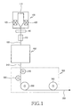
- FIG. 1 shows the construction of an apparatus for drawing an optical fiber according to the present invention.
- the apparatus comprises a heating furnace 100 for heating an optical fiber preform 110; a coating unit 200 for forming a second optical fiber 240, which has at least one coating layer formed thereon; a spin unit 300 for forming a third optical fiber 350, which incorporates a twist in a predetermined direction; an outer diameter measuring device 140; and, a cooler 150.
- the heating furnace 100 includes at least one heater 120, 130 for heating a lower portion of the optical fiber preform 110.
- the coating unit 200 may be configured either as a wet-on-wet type or as a wet-on-dry type, according to how the coating layers, which are formed on the first optical fiber 160, are cured. The construction of each of the coating units 200 will now be described with reference to FIGs. 3 and 4, respectively.
- FIG. 3 shows the wet-on-wet type construction of the coating unit 200 shown in FIG. 1.
- the coating unit 200 includes a first coating machine 210 for passing the first optical fiber 160 through a coating liquid consisting of a UV-curable polymer material; a second coating machine 220 for passing the first optical fiber 160 through a coating liquid consisting of a UV-curable polymer material with the viscosity lower than that of the first coating machine 210; and, a UV lamp 230 for curing the coating layer of the first optical fiber 160 to form a second optical fiber 240, which has coating layers of a multi-layered structure.
- FIG. 4 shows the wet-on-dry type construction of the coating unit 200 shown in FIG. 1.
- the coating unit 200 includes a first coating machine 210 for passing the first optical fiber 160 through a coating liquid consisting of a UV-curable polymer material; a first UV lamp 230a for curing the coating layer of the first optical fiber 160, which has passed the first coating machine 210; a second coating machine 220 for passing the first optical fiber 160 through a coating liquid consisting of a UV-curable polymer material and the viscosity of which is lower than that of the first coating machine 210; and, a second UV lamp 230b for curing the coating layer of the first optical fiber 160 to form a second optical fiber 240, which has coating layers of a multi-layered structure.
- the UV-curable polymer may include a acrylate-based material or a vinyl-based material.
- a viscosity of each of the coating liquids in a different manner, which are injected to the first and second coating machines 210 and 220 respectively, it is possible to regulate the degree of residual twist, which is applied to the second optical fiber 240 via a spin wheel.
- the intensity of the UV lamps 230, 230a, 230b it is also possible to regulate the degree of residual twist, which is applied to the second optical fiber 240 via a spin wheel 330, as well as the degree of the polarization mode dispersion of the third optical fiber 350.
- FIG. 9 is a graph illustrating the relationship between the polarization mode dispersion and the number of turns according to changes in the intensity of a UV lamp. As shown, as the intensity of the UV lamp increases, the residual twist applied to the second optical fiber is increased, while the polarization mode dispersion of the third optical fiber is decreased.
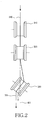
- FIG. 2 shows the construction of the spin unit 300 shown in FIG. 1.
- the spin unit 300 includes a spin wheel 330, a guide wheel 320, an auxiliary wheel 310, and a capstan for controlling the drawing rate of the first, second, and third optical fibers 160, 240, and 350.
- the spin wheel 330 is adapted to draw the second optical fiber 240 in a predetermined direction slanted relative to a drawing axis 401 of the first optical fiber 160, so that the second optical fiber 240 is made to incorporate a residual twist in a direction to obtain the third optical fiber 350.
- the spin wheel 330 is slanted at an angle clockwise or counterclockwise about the drawing axis 401, along which the first and second optical fibers 160, 240 are drawn, so that the second optical fiber 240 is made to incorporate a residual twist to obtain the third optical fiber 350.
- the guide wheel 320 is positioned parallel to the drawing axis 401 between the spin wheel 330 and the coating unit 200 to guide the second optical fiber 240, which is inputted to the spin unit 330 from the coating unit 200, so that it does not to go out of its path along the drawing axis 401 due to the spin wheel 330.
- the guide wheel 320 guides the second optical fiber 240 to travel along the drawing axis 401 between the spin wheel 330 and the coating unit 200.
- the auxiliary wheel 310 is positioned parallel to the drawing axis 401 between the guide wheel 320 and the coating unit 200, and is adapted to control excessive rotational force caused by an angle difference between the spin wheel 330 and the drawing axis 401.
- FIG. 5 is a sectional diagram showing the first optical fiber shown in FIG. 1.
- the first optical fiber 160 includes a core 161, which is positioned in its center portion, and a clad 162, which surrounds the outer peripheral surface of the core 161.
- FIG. 6 is a sectional diagram showing the second optical fiber shown in FIG. 1.
- the second optical fiber 240 includes a first optical fiber 160, as well as first and second coating layers 241 and 242, which surround the outer peripheral surface of the clad 162.
- FIG. 7 is a graph illustrating the distribution of the means and the standard deviations of the polarization mode dispersion values of optical fibers according to the present invention.
- FIG. 7 presents the measurements of the polarization mode dispersion of a plurality of optical fibers fabricated according to the present invention, and shows the change in polarization mode dispersion vs. number of turns which the optical fibers have. As the number of turns is increased, the polarization mode dispersion is decreased. However, if the number of turns exceeds a critical point, the polarization mode dispersion is increased due to shear stress.
- FIG. 8 is a graph illustrating the difference between the present invention and the prior art in terms of changes in diameter vs. length of optical fibers. As shown, optical fibers according to the present invention exhibit an even distribution with a standard deviation of ⁇ 0.04 ⁇ m, while optical fibers fabricated according to the prior art exhibit severe irregularity with a standard deviation of ⁇ 0.15 ⁇ m.
- the present invention is advantageous in that it is possible to regulate the degree of twist applied to optical fibers, by coating the optical fibers with a plurality of coating liquids with different viscosity and selectively adjusting the viscosity of the coating liquids.
Abstract
Description
Claims (14)
- A method for drawing an optical fiber, the method comprising the steps of:(a) heating one end of an optical fiber preform to draw an optical fiber;(b) coating a plurality of layers having a different viscosity on an outer peripheral surface of the optical fiber; and,(c) by drawing the coated optical fiber in a slated direction by a predetermined angle.
- The method as claimed in claim 1, wherein the step (b) of coating the outer peripheral surface of the optical fiber with a different viscosity is performed a predetermined number of times.
- The method as claimed in claim 1, wherein each of the coating layers is formed with a coating liquid, the viscosity of which is gradually decreased as the layer is positioned farther from the center of the optical fiber.
- The method as claimed in claim 3, wherein the coating liquids include polymer acrylate materials having a different viscosity.
- The method as claimed in claim 3, wherein the coating liquids include curable polymer materials having a different viscosity.
- The method as claimed in claim 3, wherein the coating liquids include polymer vinyl materials having a different viscosity.
- An apparatus for drawing an optical fiber, comprising:a heating furnace for heating an optical fiber preform;a coating unit for coating a first optical fiber, which is drawn from the heating furnace, and providing it with at least one coating layer having a different viscosity on its outer peripheral surface to form a second optical fiber; and,a spin unit for making the second optical fiber incorporate a twist in a direction to form a third optical fiber, the spin unit having a spin wheel for drawing the second optical fiber with a predetermined angle slanted relative to a drawing axis of the first optical fiber to form the third optical fiber.
- The apparatus as claimed in claim 7, wherein the spin unit further includes:a guide wheel positioned parallel to the drawing axis between the spin wheel and the coating unit to guide the second optical fiber, which is inputted to the spin unit from the coating unit, so that it travels along the drawing axis and does not go out of its path due to the spin wheel;an auxiliary wheel positioned parallel to the drawing axis between the guide wheel and the coating unit to apply a constant twist to the second optical fiber from the spin wheel; and,a capstan for controlling the drawing rate of the first, second, and third optical fibers.
- The apparatus as claimed in claim 7, further comprising:an outer diameter measuring device for measuring the outer diameter of the first optical fiber, which is drawn from the heating furnace; anda cooler for cooling the first optical fiber, which has passed the outer diameter measuring device.
- The apparatus as claimed in claim 7, wherein the coating unit includes:a first coating machine for moving the first optical fiber through a coating liquid, which consists of a UV-curable polymer material;a second coating machine for moving the first optical fiber, which has passed the first coating machine, through a coating liquid, which consists of a UV-curable polymer material and the viscosity of which is lower than that of the first coating machine; and,a UV lamp for curing the coating layer of the first optical fiber, which has passed the second coating machine, to form a second optical fiber, which has coating layers of a multi-layered structure.
- The apparatus as claimed in claim 10, wherein the UV-curable polymer includes an acrylate-based material or a vinyl-based material.
- The apparatus as claimed in claim 7, wherein the coating unit includes:a first coating machine for coating the first optical fiber with a coating liquid, which consists of a UV-curable polymer material;a first UV lamp for curing the coating layer of the first optical fiber, which has passed the first coating machine;a second coating machine for coating the first optical fiber, which has passed the first UV lamp, with a coating liquid, which consists of a UV-curable polymer material and the viscosity of which is lower than that of the first coating machine; and,a second UV lamp for curing the coating layer of the first optical fiber, which has passed the second coating machine, to form a second optical fiber, which has coating layers of a multi-layered structure.
- The apparatus as claimed in claim 7, wherein the residual twist of the third optical fiber is selectively controlled to be under 1.5 turn/M.
- The apparatus as claimed in claim 7, wherein the third optical fiber has a cable polarization mode dispersion link design value of 0.2 ps /
Applications Claiming Priority (2)
| Application Number | Priority Date | Filing Date | Title |
|---|---|---|---|
| KR1020040013921A KR100566218B1 (en) | 2004-03-02 | 2004-03-02 | Apparatus and method for drawing optical fiber |
| KR2004013921 | 2004-03-02 |
Publications (2)
| Publication Number | Publication Date |
|---|---|
| EP1571132A2 true EP1571132A2 (en) | 2005-09-07 |
| EP1571132A3 EP1571132A3 (en) | 2006-04-26 |
Family
ID=34747974
Family Applications (1)
| Application Number | Title | Priority Date | Filing Date |
|---|---|---|---|
| EP04021568A Withdrawn EP1571132A3 (en) | 2004-03-02 | 2004-09-10 | Method and apparatus for drawing an optical fibre |
Country Status (5)
| Country | Link |
|---|---|
| US (1) | US20050194704A1 (en) |
| EP (1) | EP1571132A3 (en) |
| JP (1) | JP2005247683A (en) |
| KR (1) | KR100566218B1 (en) |
| CN (1) | CN1664629A (en) |
Families Citing this family (5)
| Publication number | Priority date | Publication date | Assignee | Title |
|---|---|---|---|---|
| FR2967155B1 (en) * | 2010-11-08 | 2017-12-15 | Delachaux Sa | IMPROVED OPTICAL FIBER GUIDING DEVICE |
| JP5948136B2 (en) * | 2011-05-27 | 2016-07-06 | 株式会社フジクラ | Optical fiber and manufacturing method thereof |
| US10036108B2 (en) * | 2013-11-26 | 2018-07-31 | Corning Incorporated | Apparatus and method for applications of optical fiber coatings |
| WO2017088167A1 (en) * | 2015-11-27 | 2017-06-01 | 住友电气工业株式会社 | Optical fibre swinging device and method for manufacturing optical fibre |
| CN106772856A (en) * | 2016-12-28 | 2017-05-31 | 谢建毫 | A kind of optical fiber is around fine device |
Citations (10)
| Publication number | Priority date | Publication date | Assignee | Title |
|---|---|---|---|---|
| EP0582405A1 (en) * | 1992-08-03 | 1994-02-09 | AT&T Corp. | Method of drawing an optical fibre and fibre produced thereby |
| WO1997030945A1 (en) * | 1996-02-26 | 1997-08-28 | Corning Incorporated | Method and apparatus for providing controlled spin in optical fiber |
| EP0795521A1 (en) * | 1996-03-14 | 1997-09-17 | Sumitomo Electric Industries, Ltd | Method and apparatus for drawing an optical fiber of reduced polarisation mode dispersion from a preform |
| US5704960A (en) * | 1995-12-20 | 1998-01-06 | Corning, Inc. | Method of forming an optical fiber for reduced polarization effects in amplifiers |
| EP1116701A1 (en) * | 1998-09-24 | 2001-07-18 | Sumitomo Electric Industries, Ltd. | Method for producing optical fiber |
| US6324872B1 (en) * | 1996-04-12 | 2001-12-04 | Corning Incorporated | Method and apparatus for introducing controlled spin in optical fibers |
| US6427044B1 (en) * | 1999-06-23 | 2002-07-30 | Sumitomo Electric Industries, Ltd. | Optical fiber |
| CN1472153A (en) * | 2003-03-28 | 2004-02-04 | �ӳɹ� | Manufacture of low polarization mode dispersion single mode optical fibers and products thereby |
| US20040042747A1 (en) * | 2002-08-31 | 2004-03-04 | Kim Chul-Min | Method for monitoring spin imparted on optical fiber and method for making optical fiber by using the same |
| WO2005063640A1 (en) * | 2003-12-26 | 2005-07-14 | Fujikura Ltd. | Optical fiber twisting device, method of manufacturing optical fiber, and optical fiber |
-
2004
- 2004-03-02 KR KR1020040013921A patent/KR100566218B1/en not_active IP Right Cessation
- 2004-08-06 US US10/913,212 patent/US20050194704A1/en not_active Abandoned
- 2004-09-09 CN CN2004100770402A patent/CN1664629A/en active Pending
- 2004-09-10 EP EP04021568A patent/EP1571132A3/en not_active Withdrawn
-
2005
- 2005-02-28 JP JP2005053121A patent/JP2005247683A/en not_active Abandoned
Patent Citations (10)
| Publication number | Priority date | Publication date | Assignee | Title |
|---|---|---|---|---|
| EP0582405A1 (en) * | 1992-08-03 | 1994-02-09 | AT&T Corp. | Method of drawing an optical fibre and fibre produced thereby |
| US5704960A (en) * | 1995-12-20 | 1998-01-06 | Corning, Inc. | Method of forming an optical fiber for reduced polarization effects in amplifiers |
| WO1997030945A1 (en) * | 1996-02-26 | 1997-08-28 | Corning Incorporated | Method and apparatus for providing controlled spin in optical fiber |
| EP0795521A1 (en) * | 1996-03-14 | 1997-09-17 | Sumitomo Electric Industries, Ltd | Method and apparatus for drawing an optical fiber of reduced polarisation mode dispersion from a preform |
| US6324872B1 (en) * | 1996-04-12 | 2001-12-04 | Corning Incorporated | Method and apparatus for introducing controlled spin in optical fibers |
| EP1116701A1 (en) * | 1998-09-24 | 2001-07-18 | Sumitomo Electric Industries, Ltd. | Method for producing optical fiber |
| US6427044B1 (en) * | 1999-06-23 | 2002-07-30 | Sumitomo Electric Industries, Ltd. | Optical fiber |
| US20040042747A1 (en) * | 2002-08-31 | 2004-03-04 | Kim Chul-Min | Method for monitoring spin imparted on optical fiber and method for making optical fiber by using the same |
| CN1472153A (en) * | 2003-03-28 | 2004-02-04 | �ӳɹ� | Manufacture of low polarization mode dispersion single mode optical fibers and products thereby |
| WO2005063640A1 (en) * | 2003-12-26 | 2005-07-14 | Fujikura Ltd. | Optical fiber twisting device, method of manufacturing optical fiber, and optical fiber |
Also Published As
| Publication number | Publication date |
|---|---|
| EP1571132A3 (en) | 2006-04-26 |
| CN1664629A (en) | 2005-09-07 |
| US20050194704A1 (en) | 2005-09-08 |
| JP2005247683A (en) | 2005-09-15 |
| KR20050088551A (en) | 2005-09-07 |
| KR100566218B1 (en) | 2006-03-29 |
Similar Documents
| Publication | Publication Date | Title |
|---|---|---|
| EP1325894B1 (en) | Multimode optical fibers with increased bandwith | |
| EP0582405B1 (en) | Method of drawing an optical fibre and fibre produced thereby | |
| CA1175268A (en) | Fiber optic cable and method of manufacture | |
| US20090052853A1 (en) | Holey fiber and method of manufacturing the same | |
| AU2007361213B2 (en) | Process for manufacturing an optical fiber and an optical fiber so obtained | |
| CN108089259A (en) | Multi-core optical fiber | |
| CA1204594A (en) | Process for obtaining an object with a chiralic structure resulting from drawing from a softened material source and device for performing this process | |
| EP1571132A2 (en) | Method and apparatus for drawing an optical fibre | |
| CN1531664A (en) | Method for producing optical fiber telecommunications cable with reduced polarization mode dispersion | |
| KR100547755B1 (en) | Optical fiber manufacturing apparatus and method using spin | |
| JP3952949B2 (en) | Optical fiber and manufacturing method thereof | |
| US20040179799A1 (en) | Fiber optic cable comprising a core surrounded by coating having a radially-varying elastic modulus | |
| CA2301033A1 (en) | Draw constant downfeed process | |
| US11518709B2 (en) | Optical fiber coating die assembly having inlet tube | |
| US20030108660A1 (en) | Device/method to improve coating diameter and uniformity with adjustable sizing die | |
| JP2004175611A (en) | Method and apparatus for manufacturing optical fiber | |
| KR100642378B1 (en) | A device for decreasing pmd by changing pressure around optical fiber and apparatus for making an optical fiber having low polarization mode dispersion by using the same | |
| EP0842909A1 (en) | Apparatus and method for forming an optical fiber | |
| CN217323881U (en) | Special optical fiber drawing device | |
| KR100872235B1 (en) | Single mode optical fiber drawing method for polarization mode dispersion reduction and Optical fiber using the same | |
| JP3895583B2 (en) | Optical fiber drawing method | |
| JP2003212588A (en) | Production method of optical fiber | |
| JPS61249008A (en) | Optical fiber | |
| JP2003040639A (en) | Production method for single mode optical fiber | |
| JP2002189154A (en) | Coated optical fiber tape |
Legal Events
| Date | Code | Title | Description |
|---|---|---|---|
| PUAI | Public reference made under article 153(3) epc to a published international application that has entered the european phase |
Free format text: ORIGINAL CODE: 0009012 |
|
| 17P | Request for examination filed |
Effective date: 20040910 |
|
| AK | Designated contracting states |
Kind code of ref document: A2 Designated state(s): AT BE BG CH CY CZ DE DK EE ES FI FR GB GR HU IE IT LI LU MC NL PL PT RO SE SI SK TR |
|
| AX | Request for extension of the european patent |
Extension state: AL HR LT LV MK |
|
| PUAL | Search report despatched |
Free format text: ORIGINAL CODE: 0009013 |
|
| AK | Designated contracting states |
Kind code of ref document: A3 Designated state(s): AT BE BG CH CY CZ DE DK EE ES FI FR GB GR HU IE IT LI LU MC NL PL PT RO SE SI SK TR |
|
| AX | Request for extension of the european patent |
Extension state: AL HR LT LV MK |
|
| AKX | Designation fees paid |
Designated state(s): DE FR GB |
|
| STAA | Information on the status of an ep patent application or granted ep patent |
Free format text: STATUS: THE APPLICATION HAS BEEN WITHDRAWN |
|
| 18W | Application withdrawn |
Effective date: 20070820 |