EP1571066A2 - Pressure yoke for automotive rack-and-pinion steering gear - Google Patents
Pressure yoke for automotive rack-and-pinion steering gear Download PDFInfo
- Publication number
- EP1571066A2 EP1571066A2 EP05002859A EP05002859A EP1571066A2 EP 1571066 A2 EP1571066 A2 EP 1571066A2 EP 05002859 A EP05002859 A EP 05002859A EP 05002859 A EP05002859 A EP 05002859A EP 1571066 A2 EP1571066 A2 EP 1571066A2
- Authority
- EP
- European Patent Office
- Prior art keywords
- rack
- pinion steering
- pressure piece
- pinion
- steering system
- Prior art date
- Legal status (The legal status is an assumption and is not a legal conclusion. Google has not performed a legal analysis and makes no representation as to the accuracy of the status listed.)
- Ceased
Links
Images


Classifications
-
- B—PERFORMING OPERATIONS; TRANSPORTING
- B62—LAND VEHICLES FOR TRAVELLING OTHERWISE THAN ON RAILS
- B62D—MOTOR VEHICLES; TRAILERS
- B62D3/00—Steering gears
- B62D3/02—Steering gears mechanical
- B62D3/12—Steering gears mechanical of rack-and-pinion type
- B62D3/123—Steering gears mechanical of rack-and-pinion type characterised by pressure yokes
-
- Y—GENERAL TAGGING OF NEW TECHNOLOGICAL DEVELOPMENTS; GENERAL TAGGING OF CROSS-SECTIONAL TECHNOLOGIES SPANNING OVER SEVERAL SECTIONS OF THE IPC; TECHNICAL SUBJECTS COVERED BY FORMER USPC CROSS-REFERENCE ART COLLECTIONS [XRACs] AND DIGESTS
- Y10—TECHNICAL SUBJECTS COVERED BY FORMER USPC
- Y10T—TECHNICAL SUBJECTS COVERED BY FORMER US CLASSIFICATION
- Y10T74/00—Machine element or mechanism
- Y10T74/19—Gearing
- Y10T74/19623—Backlash take-up
-
- Y—GENERAL TAGGING OF NEW TECHNOLOGICAL DEVELOPMENTS; GENERAL TAGGING OF CROSS-SECTIONAL TECHNOLOGIES SPANNING OVER SEVERAL SECTIONS OF THE IPC; TECHNICAL SUBJECTS COVERED BY FORMER USPC CROSS-REFERENCE ART COLLECTIONS [XRACs] AND DIGESTS
- Y10—TECHNICAL SUBJECTS COVERED BY FORMER USPC
- Y10T—TECHNICAL SUBJECTS COVERED BY FORMER US CLASSIFICATION
- Y10T74/00—Machine element or mechanism
- Y10T74/19—Gearing
- Y10T74/19642—Directly cooperating gears
- Y10T74/1967—Rack and pinion
Definitions
- the invention relates to a rack and pinion steering for a motor vehicle, with a Steering housing, in which a rack is mounted longitudinally displaceable, as well a meshing with the rack pinion and a pressure piece on the one of an engagement side with the pinion opposite side of Rack is arranged and with the help of a spring in the axial direction against the rack is biased, wherein the pressure piece in its interior a the contour of the rack adapted, rotatable guide roller with a support surface having, at the rack with a corresponding support surface is applied, wherein the wings are arranged to each other so that a Rotation of the rack in the circumferential direction is prevented.
- Such rack and pinion steering systems are known from the prior art for a long time previously known.
- the rack is in the longitudinal direction slidably guided in a steering box.
- a rotatable in the steering housing stored pinion engages the toothing of the rack and causes at Rotation of the rotatably connected to the pinion steering column, the lateral displacement the rack, in turn, via tie rods and stub axles leads to a pivoting of the steered wheels of the motor vehicle.
- Engage the pinion in the rack is held backlash by one opposite the pinion on the rack fitting pressure piece under spring preload push the rack against the pinion.
- the pressure piece must be there on the one hand can transmit the required contact pressure and on the other provide a bearing surface, which when moving the rack on the Pressure piece no significant frictional forces and no significant wear causes.
- Such a rack and pinion steering is known from DE 82 03 943 U.
- the rack has two wings on, which are inclined symmetrically against the toothing plane.
- to Rack and pinion steering continues to be a leader in a pressure piece is arranged and also has two wings.
- the wings of the Rack are made by cutting material removal in the initial state generated round rack.
- the wings of the leadership are by two arranged in the pressure piece outer rings of a ball bearing, whose Lateral surfaces forming the wings, also symmetrically inclined the toothing plane are arranged. It is obvious, that by such a position of the wings of the rack and guide roller a rotation of the rack is prevented in the circumferential direction.
- the disadvantage here is the complex design of the wings of Rack and guide roller. For one, the machining of the Rack expensive and therefore expensive, because a significant amount of material to remove is. On the other hand, the pressure piece is very complicated and constructed thus also costly. So have two ball bearings on each one Bolt can be accommodated in the pressure piece, which makes great demands on the Mounting poses and also claimed additional space.
- this object is achieved by the characterizing part of Claim 1 in conjunction with the preamble thereof achieved in that the Support surface of the rack as one within the circular rack lying recess is formed.
- the Support surface of the rack as one within the circular rack lying recess is formed.
- the invention is intended to be understood be that in the lower part of the rack, that is in the range of Guide roller whose circle or periphery only very slightly interrupted is.
- the bearing surface of the Rack should be semicircular or V-shaped. Both variants stand equally side by side and can be based on Their uncomplicated geometric cross-sectional shape also simpler Insert the way into the rack.
- the leadership role be designed as a rotationally symmetrical body, which is to his Rotation axis symmetrically inclined wings, whose extensions meet in a radially outer point.
- the pressure piece should be in two parts be formed and either by a fixing screw or by a fastening pin held together. In the sense of the invention is thereby under fastening screw to see a connecting element, the is inserted outside, while a connecting pin is inserted from the inside.
- the pressure piece from a Be made of plastic.
- Such plungers have a specific one lighter weight and have to others also relatively good sliding properties in a surrounding bore hole.
- both halves of the pressure piece a career for the spaced apart angular contact bearings in the form of an insert form.
- From claim 10 shows another type of leadership role, as a two-part rotationally symmetrical body is formed, to its axis of rotation symmetrically inclined wings, whose extensions meet in a radially inward point, the two-part rotationally symmetric trained body concentrically enclosed by an outer ring, the corresponding, also symmetrical to the axis of rotation having inclined wings.
- the pressure piece on its lateral surface with a circumferential recess be provided, in which an O-ring is inserted.
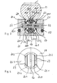
- FIG. 5 shows a housing 1 in which a pinion 2, which merges into a steering shaft 3, is mounted.
- a pressure piece 5 is arranged, which is the from the pinion 2 on the rack 4 transmitted force is substantially supported.
- the pressure piece 5 is in an unspecified receiving bore of the housing 1 housed. It is of a between the pressure piece 5 and a rigidly connected to the housing 1 cover 6 arranged spring. 7 biased in the direction of the rack 4.
- a guide roller 8 is housed, consisting of two as deep groove ball bearings trained rolling bearings 9 is made, each on a support shaft 10 are held.
- the support shafts 10 and thus the bearings 9 are under arranged at a certain angle to the toothing plane, so that the inclined bearing outer rings of the bearings 9 with their wings 12th abut the designated 11 wings of the rack 4. It lies obvious that the rack 4 do not move in the circumferential direction can, if a moment, for example, by a ball screw, applied would.
- FIG. 1 shows an arrangement according to the invention of a pressure piece 14 and a rack 13, whereby according to known prior art the rack 13 at its side facing away from the pressure piece 14 side with a Gearing is provided 13.1, in which engages an unillustrated pinion.
- the rack 13th At her the toothing 13.1 opposite side, the rack 13th a recess 13.2, which in the exemplary embodiment is V-shaped is, so that two wings 13.3, 13.4 are formed, which are symmetrical to Teeth 13.1 are inclined.
- the pressure piece 14 consists of the two Halves 14.1, 14.2, which are held together by a fastening screw 15 are.
- the guide roller 19 is rotatably mounted, wherein the axis of rotation 19.1 at the same time the center axis of the fastening screw 15 is.
- the guide roller 19 is as a rotationally symmetrical body formed, the symmetrically inclined to its axis of rotation 19.1 Has wings 19.2, 19.3, located in a radially outer Unite point.
- the leading role 19 in their midst the largest diameter, continuous in both axial direction drops.
- the guide roller 19 is in the pressure piece 14 via the two spaced angular needle bearings 16, 17 rotatable held, the bearing needles 16.1, 17.1 in a cage 16.2, 17.2 out are.
- the raceways of the angular needle bearings 16, 17 are on the one hand of the Wings 19.2, 19.3 of the guide roller 19 and on the other hand of the likewise symmetrically inclined surfaces 14.1.1, 14.2.1 of Pressure piece halves 14.1, 14.2 formed.
- the helical needle bearings 16, 17 are mutually set in X-arrangement, d. h., Their pressure lines are inclined from outside inward toward the center of the guide roller 19.
- To the arrangement heard further includes a spring 18, the pressure member 14 against the rack 13 presses, and an O-ring 20 in a groove 14.3 of the pressure piece 14 is arranged.
- a desired bearing preload can be adjusted by tightening the mounting screw 15 the two halves 14.1, 14.2 of the pressure piece 14, and thus the wings 19.2, 19.3 and the tracks 14.1.1, 14.2.1, are moved towards each other.
- the pressure piece 14 shown in FIG. 2 differs from that in FIG. 1 shown only in that the tracks 14.1.1, 14.2.1 not from the two halves 14.1, 14.2 of the pressure piece 14 are formed, but by Insert parts in the form of metal discs 16.3, 17.3. These will especially when the pressure piece 14 from a non-metallic material, for example made of a plastic is.
- the provided in Figures 3 and 4 with the reference numeral 21 pressure piece is formed in one piece and has a guide roller 25 by means of fastening pin 22 is held within the pressure piece 21.
- This is in two parts formed and consists of the two parts 25.1, 25.2, their wings 25.1.1, 25.2.1 are symmetrically inclined to each other and in a radial meet inside point.
- the guide roller 25 decreases in diameter from outside to inside. Belongs to the pressure piece 21 also the outer ring 26, which has a prismatic profile, on the one hand the wings 13.3, 13.4 of the rack 13 and on the other hand the wings 25.1.1, 25.2.1 of parts 25.1, 25.2.
- inner and outer wings 26.1, 26.2, 26.3, 26.4 of the outer ring 26 are formed, which also run symmetrically inclined to each other.
- the wings 25.1.1, 25.2.1, 26.1, 26.2 are arranged at both helical needle bearings 23, 24, which are set to each other in O arrangement, that is, their printing lines run diagonally from inside to outside.
- the spring element belongs 27 in the form of a plate spring for inventively designed Pressure piece 21, which arranged on both sides spring elements 27 the two halves 25.1 and 25.2 of the guide roller 25 to move each other and these on their wings 25.1.1, 25.2.1 the bearing needles 23.1, 24.1 against Press the inner wings 26.1, 26.2 of the outer ring.
Abstract
Description
Die Erfindung betrifft eine Zahnstangenlenkung für ein Kraftfahrzeug, mit einem Lenkgehäuse, in dem eine Zahnstange längsverschieblich gelagert ist, sowie einem mit der Zahnstange kämmenden Ritzel und einem Druckstück, das auf einer einer Eingriffsseite mit dem Ritzel gegenüberliegenden Seite der Zahnstange angeordnet ist und mit Hilfe einer Feder in axialer Richtung gegen die Zahnstange vorgespannt ist, wobei das Druckstück in seinem Inneren eine der Kontur der Zahnstange angepaßte, drehbare Führungsrolle mit einer Tragfläche aufweist, an der die Zahnstange mit einer korrespondierenden Tragfläche anliegt, wobei die Tragflächen zueinander so angeordnet sind, dass ein Verdrehen der Zahnstange in Umfangrichtung verhindert ist.The invention relates to a rack and pinion steering for a motor vehicle, with a Steering housing, in which a rack is mounted longitudinally displaceable, as well a meshing with the rack pinion and a pressure piece on the one of an engagement side with the pinion opposite side of Rack is arranged and with the help of a spring in the axial direction against the rack is biased, wherein the pressure piece in its interior a the contour of the rack adapted, rotatable guide roller with a support surface having, at the rack with a corresponding support surface is applied, wherein the wings are arranged to each other so that a Rotation of the rack in the circumferential direction is prevented.
Derartige Zahnstangenlenkungen sind aus dem Stand der Technik seit längerem vorbekannt. Bei diesen Lenkungen wird die Zahnstange in Längsrichtung verschiebbar in einem Lenkgehäuse geführt. Ein in dem Lenkgehäuse drehbar gelagertes Ritzel greift in die Verzahnung der Zahnstange ein und bewirkt bei Drehung der mit dem Ritzel drehfest verbundenen Lenksäule die seitliche Verlagerung der Zahnstange, die wiederum über Spurstangen und Achsschenkel zu einer Verschwenkung der gelenkten Räder des Kraftfahrzeuges führt. Der Eingriff des Ritzels in die Zahnstange wird spielfrei gehalten, indem ein gegenüber dem Ritzel an der Zahnstange anliegendes Druckstück unter Federvorspannung die Zahnstange gegen das Ritzel drückt. Das Druckstück muß dabei zum einen die erforderliche Anpreßkraft übertragen können und zum anderen eine Lagerfläche bieten, die bei der Verschiebung der Zahnstange auf dem Druckstück keine nennenswerten Reibkräfte und keinen wesentlichen Verschleiß hervorruft. Wird nun die über das Ritzel von der Hand des Fahrers aufgebrachte Lenkkraft durch einen Kugelgewindetrieb verstärkt, so wird durch die Momentübertragung die Zahnstange versucht sein, sich über ihre axiale Länge in Umfangsrichtung zu verdrehen. Dies versucht man dadurch zu verhindern, indem die Tragflächen von Führungsrolle und Zahnstange so zueinander angeordnet sind, dass sie sich einem Verdrehen der Zahnstange entgegen stellen.Such rack and pinion steering systems are known from the prior art for a long time previously known. In these steering, the rack is in the longitudinal direction slidably guided in a steering box. A rotatable in the steering housing stored pinion engages the toothing of the rack and causes at Rotation of the rotatably connected to the pinion steering column, the lateral displacement the rack, in turn, via tie rods and stub axles leads to a pivoting of the steered wheels of the motor vehicle. Of the Engage the pinion in the rack is held backlash by one opposite the pinion on the rack fitting pressure piece under spring preload push the rack against the pinion. The pressure piece must be there on the one hand can transmit the required contact pressure and on the other provide a bearing surface, which when moving the rack on the Pressure piece no significant frictional forces and no significant wear causes. Will now be applied over the pinion from the driver's hand Steering force amplified by a ball screw, so is by the Moment transfer the rack is trying to get over its axial length to twist in the circumferential direction. This is an attempt to prevent this by the wings of leadership and rack so arranged to each other are that they oppose a twisting of the rack.
Eine derartige Zahnstangenlenkung ist aus der DE 82 03 943 U bekannt. Wie Figur 5 dieser Vorveröffentlichung zeigt, weist die Zahnstange zwei Tragflächen auf, die symmetrisch gegen die Verzahnungsebene geneigt sind. Zur Zahnstangenlenkung gehört weiter eine Führungsrolle, die in einem Druckstück angeordnet ist und ebenfalls zwei Tragflächen aufweist. Die Tragflächen der Zahnstange werden durch spanenden Materialabtrag der im Ausgangszustand runden Zahnstange erzeugt. Die Tragflächen der Führungsrolle werden durch zwei im Druckstück angeordnete Außenringe eines Kugellagers gebildet, deren Mantelflächen, die die Tragflächen bilden, ebenfalls symmetrisch geneigt gegenüber der Verzahnungsebene angeordnet sind. Es liegt auf der Hand, dass durch eine solche Stellung der Tragflächen von Zahnstange und Führungsrolle ein Verdrehen der Zahnstange in Umfangsrichtung verhindert ist.Such a rack and pinion steering is known from DE 82 03 943 U. As Figure 5 shows this prior publication, the rack has two wings on, which are inclined symmetrically against the toothing plane. to Rack and pinion steering continues to be a leader in a pressure piece is arranged and also has two wings. The wings of the Rack are made by cutting material removal in the initial state generated round rack. The wings of the leadership are by two arranged in the pressure piece outer rings of a ball bearing, whose Lateral surfaces forming the wings, also symmetrically inclined the toothing plane are arranged. It is obvious, that by such a position of the wings of the rack and guide roller a rotation of the rack is prevented in the circumferential direction.
Nachteilig dabei ist die aufwendige Ausgestaltung der Tragflächen von Zahnstange und Führungsrolle. Zum einen ist die spanende Bearbeitung der Zahnstange aufwendig und damit teuer, weil ein erheblicher Materialanteil abzutragen ist. Zum anderen ist das Druckstück sehr kompliziert aufgebaut und damit ebenfalls kostenaufwendig. So müssen zwei Kugellager über je einen Bolzen im Druckstück untergebracht werden, was große Anforderungen an die Montage stellt und darüber hinaus zusätzlichen Bauraum beansprucht.The disadvantage here is the complex design of the wings of Rack and guide roller. For one, the machining of the Rack expensive and therefore expensive, because a significant amount of material to remove is. On the other hand, the pressure piece is very complicated and constructed thus also costly. So have two ball bearings on each one Bolt can be accommodated in the pressure piece, which makes great demands on the Mounting poses and also claimed additional space.
Ausgehend von den Nachteilen des bekannten Standes der Technik ist es daher Aufgabe der Erfindung, eine wesentlich vereinfachte Zahnstangenlenkung mit Druckstück bereit zu stellen, die sich einfach fertigen lässt und Drehmomente, Radial- und Axialkräfte bei einer hohen Tragfähigkeit sicher aufnehmen kann.Based on the disadvantages of the known prior art, it is therefore Object of the invention, a much simplified rack and pinion steering with pressure piece that is easy to manufacture and torques, Safely absorb radial and axial forces at a high load capacity can.
Erfindungsgemäß wird diese Aufgabe nach dem kennzeichnenden Teil von
Anspruch 1 in Verbindung mit dessen Oberbegriff dadurch gelöst, daß die
Tragfläche der Zahnstange als eine innerhalb der kreisförmigen Zahnstange
liegende Ausnehmung ausgebildet ist. Im Sinne der Erfindung soll dabei verstanden
werden, dass im unteren Teil der Zahnstange, also im Bereich der
Führungsrolle, deren Kreislinie oder Peripherie nur sehr geringfügig unterbrochen
ist.According to the invention, this object is achieved by the characterizing part of
Dabei ist von Vorteil, dass die als Tragfläche dienende Ausnehmung durch einen einfachen spangebenden Prozess, beispielsweise durch Fräsen, in die Zahnstange eingearbeitet werden kann. Das runde Querschnittsprofil der Zahnstange bleibt dabei im wesentlichen erhalten. Es ist also gemäß dem bisherigen Stand der Technik nicht mehr erforderlich, zur Herstellung der Tragflächen Unmengen von Material spanend abzutragen.It is advantageous that serving as a support surface recess through a simple cutting process, for example, by milling, in the Rack can be incorporated. The round cross-sectional profile of Rack remains essentially preserved. So it is according to the previous one The prior art is no longer necessary for the production of the wings To remove tons of material by machining.
Weitere vorteilhafte Ausgestaltungen der Erfindung sind in den Unteransprüchen beschrieben.Further advantageous embodiments of the invention are in the subclaims described.
So geht aus den Ansprüchen 2 und 3 hervor, daß die Tragfläche der
Zahnstange halbkreisförmig oder V-förmig ausgebildet sein soll. Beide Ausführungsvarianten
stehen gleichberechtigt nebeneinander und lassen sich aufgrund
ihrer unkomplizierten geometrischen Querschnittsform auch in einfacher
Weise in die Zahnstange einbringen. It is apparent from the
Nach einem weiteren Merkmal der Erfindung gemäß Anspruch 4 ist vorgesehen,
daß die Führungsrolle über zwei in axialer Richtung voneinander
beabstandete Schrägwälzlager gehalten ist, wobei diese gemäß Anspruch 5
als Schrägnadellager ausgebildet sein sollen, die zueinander in O- oder X-Anordnung
angestellt sind. Durch diese gegeneinander angestellten Schrägwälzlager
lassen sich sowohl Radial- als auch Axialkräfte und auch Drehmomente
sicher aufnehmen.According to a further feature of the invention according to claim 4 is provided
that the leadership about two in the axial direction from each other
spaced skew bearings is held, this according to
Nach einem weiteren Merkmal der Erfindung gemäß Anspruch 6 soll die Führungsrolle
als ein rotationssymmetrischer Körper ausgebildet sein, der zu seiner
Rotationsachse symmetrisch geneigte Tragflächen aufweist, deren Verlängerungen
sich in einem radial außen liegenden Punkt treffen.According to a further feature of the invention according to
Nach einem weiterer Merkmal gemäß Anspruch 7 soll das Druckstück zweiteilig
ausgebildet sein und entweder durch eine Befestigungsschraube oder durch
einen Befestigungsstift zusammengehalten sein. Im Sinn der Erfindung ist dabei
unter Befestigungsschraube ein Verbindungselement zu sehen, das von
außen eingesetzt ist, während ein Verbindungsstift von innen eingeführt ist.According to a further feature according to
Nach einem anderen Merkmal der Erfindung soll das Druckstück aus einem Kunststoff hergestellt sein. Derartige Druckstücke haben zu einen ein spezifisch leichteres Gewicht und weisen zu anderen auch relativ gute Gleiteigenschaften in einer sie umgebenden Aufnahmebohrung auf.According to another feature of the invention, the pressure piece from a Be made of plastic. Such plungers have a specific one lighter weight and have to others also relatively good sliding properties in a surrounding bore hole.
Ist ein solches Druckstück aus Kunststoff gefertigt, so kann es gemäß Anspruch 9 zweckmäßig sein, dass beide Hälften des Druckstückes eine Laufbahn für die voneinander beabstandeten Schrägwälzlager in Form eines Einlegeteils bilden.If such a pressure piece made of plastic, it may according to claim 9 be expedient that both halves of the pressure piece a career for the spaced apart angular contact bearings in the form of an insert form.
Aus Anspruch 10 geht eine andere Art einer Führungsrolle hervor, die als ein
zweiteiliger rotationssymmetrischer Körper ausgebildet ist, der zu seiner Rotationsachse
symmetrisch geneigte Tragflächen aufweist, deren Verlängerungen
sich in einem radial innen liegenden Punkt treffen, wobei der zweiteilige rotationssymmetrisch
ausgebildete Körper konzentrisch von einem Außenring umschlossen,
der korrespondierende, ebenfalls zur Rotationsachse symmetrisch
geneigte Tragflächen aufweist.From
Gemäß Anspruch 11 ist zu dieser zweiteiligen rotationssymmetrisch ausgebildeten
Führungsrolle in vorteilhafter Weise beidseitig ein Federelement angeordnet,
das dieses mit einer axialen Kraft beaufschlagt. Auf diese Weise lässt
sich die gewünschte Lagervorspannung unkompliziert einstellen.According to
Schließlich soll nach einem letzten Merkmal der Erfindung gemäß Anspruch 12 das Druckstück an seiner Mantelfläche mit einer umlaufenden Ausnehmung versehen sein, in die ein O-Ring eingesetzt ist.Finally, according to a last feature of the invention according to claim 12 the pressure piece on its lateral surface with a circumferential recess be provided, in which an O-ring is inserted.
Die Erfindung wird an nachstehenden Ausführungsbeispielen näher erläutert.The invention will be explained in more detail in the following embodiments.
Es zeigen:
Figur - einen Längsschnitt durch ein erfindungsgemäß ausgestaltetes Druckstück mit Zahnstange,
- Figur 4
- eine Draufsicht auf ein Druckstück gemäß
Figur 3 und Figur 5- einen Längsschnitt durch ein Druckstück mit Zahnstange nach dem bisherigen Stand der Technik
- FIGS. 1, 2 and 3
- a longitudinal section through an inventively designed pressure piece with rack,
- FIG. 4
- a plan view of a pressure piece according to Figure 3 and
- FIG. 5
- a longitudinal section through a pressure piece with rack according to the prior art
Zur Darstellung des Gesamtzusammenhanges sei zunächst auf den Stand der
Technik gemäß Figur 5 verwiesen. Diese zeigt ein Gehäuse 1, in dem ein Ritzel
2, das in eine Lenkspindel 3 übergeht, gelagert ist. In die Verzahnung des
Ritzels 2 greift die Verzahnung einer Zahnstange 4 ein, die quer zum Ritzel 2
verläuft. Auf der der Eingriffsseite des Ritzels 2 mit der Zahnstange 4 gegenüberliegenden
Seite der Zahnstange 4 ist ein Druckstück 5 angeordnet, das die
vom Ritzel 2 auf die Zahnstange 4 übertragene Kraft im wesentlichen abstützt.
Das Druckstück 5 ist in einer nicht bezeichneten Aufnahmebohrung des Gehäuses
1 untergebracht. Es wird von einer zwischen dem Druckstück 5 und
einem starr mit dem Gehäuse 1 verbundenen Deckel 6 angeordneten Feder 7
in Richtung auf die Zahnstange 4 vorgespannt.To illustrate the overall context, let us first look at the state of
Reference is made to the technique according to FIG. 5. This shows a
Im Druckstück 5 ist eine Führungsrolle 8 untergebracht, die aus zwei als Rillenkugellager
ausgebildeten Wälzlagern 9 besteht, die auf je einer Tragachse
10 gehalten sind. Die Tragachsen 10 und damit die Wälzlager 9 sind unter
einem bestimmten Winkel zur Verzahnungsebene angeordnet, so dass die
schräg gestellten Lageraußenringe der Wälzlager 9 mit ihren Tragflächen 12
an den mit 11 bezeichneten Tragflächen der Zahnstange 4 anliegen. Es liegt
auf der Hand, dass sich die Zahnstange 4 in Umfangsrichtung nicht bewegen
kann, falls ein Moment, beispielsweise durch einen Kugelgewindetrieb, aufgebracht
würde.In the
In Figur 1 ist eine erfindungsgemäßes Anordnung von einem Druckstück 14
und einer Zahnstange 13 gezeigt, wobei nach bekanntem Stand der Technik
die Zahnstange 13 an ihrer vom Druckstück 14 abgewandten Seite mit einer
Verzahnung 13.1 versehen ist, in die ein nicht dargestelltes Ritzel eingreift. An
ihrer der Verzahnung 13.1 gegenüberliegenden Seite weist die Zahnstange 13
eine Ausnehmung 13.2 auf, die im Ausführungsbeispiel V-förmig ausgebildet
ist, so dass zwei Tragflächen 13.3, 13.4 gebildet sind, die symmetrisch zur
Verzahnung 13.1 geneigt sind. Das Druckstück 14 besteht aus den beiden
Hälften 14.1, 14.2, die durch eine Befestigungsschraube 15 zusammengehalten
sind. Im Druckstück 14 ist die Führungsrolle 19 drehbar gelagert, wobei
deren Rotationsachse 19.1 gleichzeitig die Mittenachse der Befestigungsschraube
15 ist. Die Führungsrolle 19 ist als ein rotationssymmetrischer Körper
ausgebildet, der zu seiner Rotationsachse 19.1 symmetrisch zueinander geneigte
Tragflächen 19.2, 19.3 aufweist, die sich in einem radial außen liegenden
Punkt vereinen. Wie die Figur weiter erkennen lässt, weist die Führungsrolle
19 in ihrer Mitte den größten Durchmesser auf, der kontinuierlich in beiden
axialen Richtung abfällt. Die Führungsrolle 19 ist im Druckstück 14 über
die beiden voneinander beabstandeten Schrägnadellager 16, 17 drehbar
gehalten, wobei die Lagernadeln 16.1, 17.1 in je einem Käfig 16.2, 17.2 geführt
sind. Die Laufbahnen der Schrägnadellager 16, 17 sind einerseits von den
Tragflächen 19.2, 19.3 der Führungsrolle 19 und andererseits von den ebenfalls
symmetrisch zueinander geneigt verlaufenden Flächen 14.1.1, 14.2.1 der
Druckstückhälften 14.1, 14.2 gebildet. Die Schrägnadellager 16, 17 sind zueinander
in X-Anordnung angestellt, d. h., ihre Drucklinien verlaufen schräg von
außen nach innen in Richtung Mittelpunkt der Führungsrolle 19. Zur Anordnung
gehört weiter eine Feder 18, die das Druckstück 14 gegen die Zahnstange
13 andrückt, sowie ein O-Ring 20, der in einer Nut 14.3 des Druckstückes
14 angeordnet ist. Wird nun über ein nicht dargestelltes Ritzel die
Zahnstange 13 seitlich verschoben, so stützt sie sich auf der Führungsrolle 19
ab, die dadurch um die sie durchdringende Befestigungsschraube 15 in Rotation
versetzt wird, wobei die Abstützung über die beiden Schrägnadellager 16,
17 realisiert ist.FIG. 1 shows an arrangement according to the invention of a
Wie die Figur 1 weiter erkennen lässt, kann eine gewünschte Lagervorspannung
eingestellt werden, indem durch Anziehen der Befestigungsschraube 15
die beiden Hälften 14.1, 14.2 des Druckstückes 14, und damit die Tragflächen
19.2, 19.3 und die Laufbahnen 14.1.1, 14.2.1, aufeinander zu bewegt werden.As the figure 1 can be seen further, a desired bearing preload
can be adjusted by tightening the mounting
Auf diese Weise ist eine aus Druckstück 14 und Zahnstange 13 bestehende Einheit geschaffen, die sich durch folgende Vorteile auszeichnet:
- kostengünstige Herstellung und Montage
- geringe Verlustreibung und hohe Laufruhe
- sichere Aufnahme von axialen- und radialen Kräften und von einwirkenden Drehmomenten
- hohe Tragfähigkeit
- cost-effective production and assembly
- low loss of friction and high smoothness
- safe absorption of axial and radial forces and acting torques
- high load capacity
Das in Figur 2 gezeigte Druckstück 14 unterscheidet sich von dem in Figur 1
gezeigten lediglich dadurch, dass die Laufbahnen 14.1.1, 14.2.1 nicht von den
beiden Hälften 14.1, 14.2 des Druckstückes 14 gebildet werden, sondern durch
Einlegeteile in Form von metallischen Laufscheiben 16.3, 17.3. Diese werden
insbesondere dann zur Anwendung kommen, wenn das Druckstück 14 aus
einem nichtmetallischen Material, beispielsweise aus einem Kunststoff, gefertigt
ist.The
Das in den Figuren 3 und 4 mit der Bezugszahl 21 versehene Druckstück ist
einteilig ausgebildet und weist eine Führungsrolle 25 auf, die mittels Befestigungsstift
22 innerhalb des Druckstückes 21 gehalten ist. Diese ist zweiteilig
ausgebildet und besteht aus den beiden Teilen 25.1, 25.2, deren Tragflächen
25.1.1, 25.2.1 symmetrisch zueinander geneigt sind und sich in einem radial
innen liegenden Punkt treffen. Anders ausgedrückt, die Führungsrolle 25 nimmt
in ihrem Durchmesser von außen nach innen ab. Zum Druckstück 21 gehört
auch der Außenring 26, der ein prismatisches Profil aufweist, das einerseits
den Tragflächen 13.3, 13.4 der Zahnstange 13 und anderseits den Tragflächen
25.1.1, 25.2.1 der Teile 25.1, 25.2 angepasst ist. Auf diese Weise sind innere
und äußere Tragflächen 26.1, 26.2, 26.3, 26.4 des Außenringes 26 gebildet,
die ebenfalls symmetrisch zueinander geneigt verlaufen. Zwischen den Tragflächen
25.1.1, 25.2.1, 26.1, 26.2 sind bei beiden Schrägnadellager 23, 24 angeordnet,
die zu einander in O-Anordnung angestellt sind, d.h., deren Drucklinien
verlaufen schräg von innen nach außen. Schließlich gehört das Federelement
27 in Form einer Tellerfeder zum erfindungsgemäß ausgebildeten
Druckstück 21, wobei diese beidseitig angeordneten Federelemente 27 die
beiden Hälften 25.1 und 25.2 der Führungsrolle 25 auf einander zu bewegen
und diese über ihre Tragflächen 25.1.1, 25.2.1 die Lagernadeln 23.1, 24.1 gegen
die inneren Tragflächen 26.1, 26.2 des Außenrings drücken. Somit ist in
einfacher Weise in der Führungsrolleneinheit eine gewünschte Vorspannung
einstellbar. The provided in Figures 3 and 4 with the
- 11
- Gehäusecasing
- 22
- Ritzelpinion
- 33
- Lenkspindelsteering shaft
- 44
- Zahnstangerack
- 55
- DruckstückPressure piece
- 66
- Deckelcover
- 77
- Federfeather
- 88th
- Führungsrolleleadership
- 99
- Wälzlagerroller bearing
- 1010
- Tragachsecarrying axle
- 1111
- Tragflächewing
- 1212
- Tragflächewing
- 1313
- Zahnstangerack
- 13.113.1
- Verzahnunggearing
- 13.213.2
- Ausnehmungrecess
- 13.313.3
- Tragflächewing
- 13.413.4
- Tragflächewing
- 1414
- DruckstückPressure piece
- 14.114.1
- Teilpart
- 14.1.114.1.1
- Laufbahncareer
- 14.214.2
- Teilpart
- 14.2.114.2.1
- Laufbahncareer
- 14.314.3
- Nutgroove
- 1515
- Befestigungsschraubefixing screw
- 1616
- SchrägnadellagerAngular needle bearings
- 16.116.1
- Lagernadelbearing needle
- 16.216.2
- KäfigCage
- 16.316.3
- Laufscheibesheave
- 1717
- SchrägnadellagerAngular needle bearings
- 17.117.1
- Lagernadelbearing needle
- 17.217.2
- KäfigCage
- 17.317.3
- Laufscheibesheave
- 1818
- Federfeather
- 1919
- Führungsrolleleadership
- 19.119.1
- Rotationsachseaxis of rotation
- 19.219.2
- Tragflächewing
- 19.319.3
- Tragflächewing
- 2020
- O-RingO-ring
- 2121
- DruckstückPressure piece
- 21.121.1
- Nutgroove
- 2222
- Befestigungsstiftfastening pin
- 2323
- SchrägnadellagerAngular needle bearings
- 23.123.1
- Lagernadelbearing needle
- 23.223.2
- KäfigCage
- 2424
- SchrägnadellagerAngular needle bearings
- 24.124.1
- Lagernadelbearing needle
- 24.224.2
- KäfigCage
- 2525
- Führungsrolleleadership
- 25.125.1
- Teilpart
- 25.1.125.1.1
- Tragflächewing
- 25.225.2
- Teilpart
- 25.2.125.2.1
- Tragflächewing
- 25.325.3
- Rotationsachseaxis of rotation
- 2626
- Außenringouter ring
- 26.126.1
- Tragflächewing
- 26.226.2
- Tragflächewing
- 26.326.3
- Tragflächewing
- 26.426.4
- Tragflächewing
- 2727
- Federelementspring element
Claims (12)
Applications Claiming Priority (2)
| Application Number | Priority Date | Filing Date | Title |
|---|---|---|---|
| DE102004010819A DE102004010819A1 (en) | 2004-03-05 | 2004-03-05 | Rack and pinion steering |
| DE102004010819 | 2004-03-05 |
Publications (2)
| Publication Number | Publication Date |
|---|---|
| EP1571066A2 true EP1571066A2 (en) | 2005-09-07 |
| EP1571066A3 EP1571066A3 (en) | 2008-05-28 |
Family
ID=34745405
Family Applications (1)
| Application Number | Title | Priority Date | Filing Date |
|---|---|---|---|
| EP05002859A Ceased EP1571066A3 (en) | 2004-03-05 | 2005-02-11 | Pressure yoke for automotive rack-and-pinion steering gear |
Country Status (3)
| Country | Link |
|---|---|
| US (1) | US20050229733A1 (en) |
| EP (1) | EP1571066A3 (en) |
| DE (1) | DE102004010819A1 (en) |
Cited By (1)
| Publication number | Priority date | Publication date | Assignee | Title |
|---|---|---|---|---|
| US20210291891A1 (en) * | 2018-08-21 | 2021-09-23 | Robert Bosch Gmbh | Twist Prevention of the Rack by Complementary Shapes |
Families Citing this family (6)
| Publication number | Priority date | Publication date | Assignee | Title |
|---|---|---|---|---|
| DE502005006463D1 (en) * | 2004-01-26 | 2009-03-05 | Schmittergroup Ag | WIRE ADJUSTABLE BEARING FOR A MOTOR VEHICLE STEERING GEAR |
| DE102004010821A1 (en) * | 2004-03-05 | 2005-09-22 | Ina-Schaeffler Kg | Rack and pinion steering |
| DE102004013167A1 (en) * | 2004-03-18 | 2005-10-06 | Ina-Schaeffler Kg | Rack and pinion steering |
| DE102008041068A1 (en) | 2008-08-07 | 2010-02-11 | Zf Lenksysteme Gmbh | Device for pressing toothed rack into pinion in toothed rack steering mechanism of motor vehicle, has thrust piece guided in direction of toothed rack by thrust piece spring, where spring is supported at end that is turned away from rack |
| DE102012108423A1 (en) | 2012-09-10 | 2014-03-13 | Thyssenkrupp Presta Aktiengesellschaft | Rack for a steering system of a motor vehicle, steering gear and pressure piece |
| US10899380B2 (en) * | 2018-11-30 | 2021-01-26 | Steering Solutions Ip Holding Corporation | Steering assembly |
Citations (5)
| Publication number | Priority date | Publication date | Assignee | Title |
|---|---|---|---|---|
| GB2036240A (en) * | 1978-11-27 | 1980-06-25 | Cam Gears Ltd | Variable ratio rack and pinion gear |
| US4215591A (en) * | 1977-02-09 | 1980-08-05 | Bishop Arthur E | Low friction rack and pinion steering gear |
| DE2913641A1 (en) * | 1979-04-05 | 1980-10-16 | Schaeffler Ohg Industriewerk | Bearing for steering rack - has ball bearing races with bearing shells used as rolling supports |
| US20020084136A1 (en) * | 2000-12-29 | 2002-07-04 | Fowlkes Edward Taylor | Power steering system with roller yoke |
| WO2002085687A2 (en) * | 2001-04-20 | 2002-10-31 | Trw Inc. | Rack and pinion steering gear with low friction roller yoke design |
Family Cites Families (18)
| Publication number | Priority date | Publication date | Assignee | Title |
|---|---|---|---|---|
| GB1168191A (en) * | 1968-04-29 | 1969-10-22 | Cam Gears Ltd | Improvements in or relating to Rack and Pinion Assemblies |
| FR2180157A5 (en) * | 1972-04-10 | 1973-11-23 | Gemmer France | |
| DE8203943U1 (en) * | 1981-02-24 | 1982-07-01 | RIV-SKF Officine di Villar Perosa S.p.A., 10123 Torino | STEERING GEARBOX FOR MOTOR VEHICLES WITH A BACK PRESSURE ELEMENT FOR THE RACK |
| KR900002221B1 (en) * | 1984-07-09 | 1990-04-06 | 미쯔비시지도오샤고오교오 가부시기가이샤 | Steering gear mechanism |
| IT8453881V0 (en) * | 1984-10-02 | 1984-10-02 | Riv Officine Di Villar Perosa | STEERING BOX FOR A VEHICLE |
| US5058448A (en) * | 1988-10-27 | 1991-10-22 | Koyo Seiko Co., Ltd. | Rack and pinion steering device |
| US5161926A (en) * | 1991-08-21 | 1992-11-10 | Xermac, Inc. | Precision head for a machine tool |
| JPH05341202A (en) * | 1992-06-08 | 1993-12-24 | Nikon Corp | Device for guiding straight line |
| US5622085A (en) * | 1995-08-15 | 1997-04-22 | Trw Inc. | Rack and pinion steering gear with improved yoke |
| US5983742A (en) * | 1998-02-05 | 1999-11-16 | Oiles America Corporation | Rack and pinion steering device with split roller rack bar support |
| DE19936539B4 (en) * | 1999-08-03 | 2005-10-27 | Daimlerchrysler Ag | Rack and pinion of a rack and pinion steering |
| US6408708B1 (en) * | 2000-08-10 | 2002-06-25 | Trw Inc. | Rack and pinion steering gear with low friction yoke assembly |
| US6467366B1 (en) * | 2000-10-26 | 2002-10-22 | Trw Inc. | Yoke bearing assembly for hydraulic power assist rack and pinion power steering system |
| US6619420B1 (en) * | 2002-04-16 | 2003-09-16 | Trw Inc. | Rack and pinion steering gear with hydraulic yoke assembly |
| DE10225718A1 (en) * | 2002-06-11 | 2004-01-08 | Zf Lenksysteme Gmbh | Rack and pinion steering |
| JP2004034829A (en) * | 2002-07-03 | 2004-02-05 | Nsk Ltd | Method for manufacturing steering device and rack spindle |
| JP2004075000A (en) * | 2002-08-22 | 2004-03-11 | Nsk Ltd | Steering device |
| US7281444B1 (en) * | 2003-12-05 | 2007-10-16 | Trw Automotive U.S. Llc | Rack and pinion gear yoke assembly |
-
2004
- 2004-03-05 DE DE102004010819A patent/DE102004010819A1/en not_active Withdrawn
-
2005
- 2005-02-11 EP EP05002859A patent/EP1571066A3/en not_active Ceased
- 2005-03-07 US US11/074,171 patent/US20050229733A1/en not_active Abandoned
Patent Citations (5)
| Publication number | Priority date | Publication date | Assignee | Title |
|---|---|---|---|---|
| US4215591A (en) * | 1977-02-09 | 1980-08-05 | Bishop Arthur E | Low friction rack and pinion steering gear |
| GB2036240A (en) * | 1978-11-27 | 1980-06-25 | Cam Gears Ltd | Variable ratio rack and pinion gear |
| DE2913641A1 (en) * | 1979-04-05 | 1980-10-16 | Schaeffler Ohg Industriewerk | Bearing for steering rack - has ball bearing races with bearing shells used as rolling supports |
| US20020084136A1 (en) * | 2000-12-29 | 2002-07-04 | Fowlkes Edward Taylor | Power steering system with roller yoke |
| WO2002085687A2 (en) * | 2001-04-20 | 2002-10-31 | Trw Inc. | Rack and pinion steering gear with low friction roller yoke design |
Cited By (1)
| Publication number | Priority date | Publication date | Assignee | Title |
|---|---|---|---|---|
| US20210291891A1 (en) * | 2018-08-21 | 2021-09-23 | Robert Bosch Gmbh | Twist Prevention of the Rack by Complementary Shapes |
Also Published As
| Publication number | Publication date |
|---|---|
| US20050229733A1 (en) | 2005-10-20 |
| DE102004010819A1 (en) | 2005-09-22 |
| EP1571066A3 (en) | 2008-05-28 |
Similar Documents
| Publication | Publication Date | Title |
|---|---|---|
| EP0770538B1 (en) | Rack and pinion gear | |
| EP2233381B1 (en) | Cost-effective gear rack steering gear | |
| EP1273812B1 (en) | Playless radial ball bearing | |
| EP0518052A1 (en) | Bearing assembly | |
| EP1571066A2 (en) | Pressure yoke for automotive rack-and-pinion steering gear | |
| DE102006031956A1 (en) | Double-row ball bearing for motor vehicle, has rows of bearing balls rolling between inner and outer rings, where row of balls are assigned to four-point-ball bearing and angular ball bearing, and inner ring is divided into path areas | |
| EP1807633A1 (en) | Pin cage, particularly for larger radial or axial roller bearings | |
| DE102016007542A1 (en) | Ball screw drive of an electromechanical power steering with deflecting body for a ball return | |
| DE102017209563A1 (en) | Floating bearing, steering gear and steering system | |
| DE112016002670T5 (en) | Gear arrangement for electric power steering | |
| DE2253460B1 (en) | Constant velocity swivel | |
| EP3982005B1 (en) | Coaxial transmission | |
| DE102005025051A1 (en) | Steering column assembly and bearings for this purpose | |
| DE10301082A1 (en) | Rolling bearing for linear movements has guide rods fitted coaxially to each other and tracks for roll bodies between guide rods and a guide sleeve | |
| DE102012108423A1 (en) | Rack for a steering system of a motor vehicle, steering gear and pressure piece | |
| DE102006043578A1 (en) | Rack pressing device for motor vehicle, has pressure piece movably guided into housing hole, loaded in direction of rack provided with pivoted shaft, and guiding unit e.g. guiding roll, rolling on shaft | |
| DE2913641A1 (en) | Bearing for steering rack - has ball bearing races with bearing shells used as rolling supports | |
| DE202016103794U1 (en) | Transmission unit for a motor vehicle | |
| EP1577192A2 (en) | Pressure yoke for automotive rack-and-pinion steering gear | |
| DE102005027516A1 (en) | Bicycle pedal has two sets of conical needle bearings both directed towards the pedal mid-point | |
| EP1571065B1 (en) | Rack-and-pinion steering gear for motor vehicles | |
| DE10314358B4 (en) | Rack and pinion steering | |
| DE102005027520A1 (en) | bottom bracket | |
| EP3819136A1 (en) | Wheel bearing unit for a motor vehicle and method for manufacturing a wheel bearing unit | |
| EP2331836B1 (en) | Universal joint, particularly for a steering column for a motor vehicle |
Legal Events
| Date | Code | Title | Description |
|---|---|---|---|
| PUAI | Public reference made under article 153(3) epc to a published international application that has entered the european phase |
Free format text: ORIGINAL CODE: 0009012 |
|
| 17P | Request for examination filed |
Effective date: 20050211 |
|
| AK | Designated contracting states |
Kind code of ref document: A2 Designated state(s): AT BE BG CH CY CZ DE DK EE ES FI FR GB GR HU IE IS IT LI LT LU MC NL PL PT RO SE SI SK TR |
|
| AX | Request for extension of the european patent |
Extension state: AL BA HR LV MK YU |
|
| RAP1 | Party data changed (applicant data changed or rights of an application transferred) |
Owner name: SCHAEFFLER KG |
|
| PUAL | Search report despatched |
Free format text: ORIGINAL CODE: 0009013 |
|
| AK | Designated contracting states |
Kind code of ref document: A3 Designated state(s): AT BE BG CH CY CZ DE DK EE ES FI FR GB GR HU IE IS IT LI LT LU MC NL PL PT RO SE SI SK TR |
|
| AX | Request for extension of the european patent |
Extension state: AL BA HR LV MK YU |
|
| 17Q | First examination report despatched |
Effective date: 20080716 |
|
| AKX | Designation fees paid |
Designated state(s): DE FR GB IT |
|
| STAA | Information on the status of an ep patent application or granted ep patent |
Free format text: STATUS: THE APPLICATION HAS BEEN REFUSED |
|
| 18R | Application refused |
Effective date: 20090109 |
|
| P01 | Opt-out of the competence of the unified patent court (upc) registered |
Effective date: 20230522 |