EP1570676B1 - Verfahren und system zur schätzung der globalen bewegung in videosequenzen - Google Patents
Verfahren und system zur schätzung der globalen bewegung in videosequenzen Download PDFInfo
- Publication number
- EP1570676B1 EP1570676B1 EP03775589A EP03775589A EP1570676B1 EP 1570676 B1 EP1570676 B1 EP 1570676B1 EP 03775589 A EP03775589 A EP 03775589A EP 03775589 A EP03775589 A EP 03775589A EP 1570676 B1 EP1570676 B1 EP 1570676B1
- Authority
- EP
- European Patent Office
- Prior art keywords
- frame
- motion
- motion vectors
- estimation
- panoramic image
- Prior art date
- Legal status (The legal status is an assumption and is not a legal conclusion. Google has not performed a legal analysis and makes no representation as to the accuracy of the status listed.)
- Expired - Lifetime
Links
Images




Classifications
-
- H—ELECTRICITY
- H04—ELECTRIC COMMUNICATION TECHNIQUE
- H04N—PICTORIAL COMMUNICATION, e.g. TELEVISION
- H04N19/00—Methods or arrangements for coding, decoding, compressing or decompressing digital video signals
- H04N19/20—Methods or arrangements for coding, decoding, compressing or decompressing digital video signals using video object coding
- H04N19/23—Methods or arrangements for coding, decoding, compressing or decompressing digital video signals using video object coding with coding of regions that are present throughout a whole video segment, e.g. sprites, background or mosaic
-
- H—ELECTRICITY
- H04—ELECTRIC COMMUNICATION TECHNIQUE
- H04N—PICTORIAL COMMUNICATION, e.g. TELEVISION
- H04N19/00—Methods or arrangements for coding, decoding, compressing or decompressing digital video signals
- H04N19/50—Methods or arrangements for coding, decoding, compressing or decompressing digital video signals using predictive coding
- H04N19/503—Methods or arrangements for coding, decoding, compressing or decompressing digital video signals using predictive coding involving temporal prediction
- H04N19/51—Motion estimation or motion compensation
- H04N19/513—Processing of motion vectors
-
- H—ELECTRICITY
- H04—ELECTRIC COMMUNICATION TECHNIQUE
- H04N—PICTORIAL COMMUNICATION, e.g. TELEVISION
- H04N19/00—Methods or arrangements for coding, decoding, compressing or decompressing digital video signals
- H04N19/50—Methods or arrangements for coding, decoding, compressing or decompressing digital video signals using predictive coding
- H04N19/503—Methods or arrangements for coding, decoding, compressing or decompressing digital video signals using predictive coding involving temporal prediction
- H04N19/51—Motion estimation or motion compensation
- H04N19/527—Global motion vector estimation
Definitions
- the present invention relates to a method and system for estimating the global motion between frames in a video sequence, and also to a method and system for generating panoramic images from video sequences using the global motion estimations.
- global motion estimations and panoramic images are produced from video sequences comprising motion-compensated and inter-frame encoded image frames.
- video contains the richest source of information while it demands the largest storage and network bandwidth due to spatial and temporal redundancy.
- MPEG1, MPEG2 and MPEG4 try to exploit the redundancy by using motion-compensated coding scheme.
- the conventional scheme to store and encode video data is based on a sequence of 2D image frames. Obviously, this kind of representation intrinsically separates the spatio-temporal connection of the content.
- information has to be represented redundantly in many frames, it also brings a heavy burden to computation, storage and transmission.
- Panoramic scene reconstruction has been an interesting research topic for several decades. By warping a sequence of images onto a single reference mosaic image, we not only obtain an overview of the content across the whole sequence but also reduce the spatio-temporal redundancy in the original sequence of images.
- An example of how frames can be built up to provide a panoramic image is shown in Figure 1
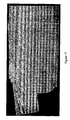
- an example panoramic image generated using a prior art technique is shown in Figure 2 .
- FIG. 1 here we show a series of consecutive image frames from a video sequence, and which have been consecutively numbered from 2 to 8.
- Frame 2 is the initial frame in the sequence, followed by frame 3, frame 4, and so on in order until frame 8.
- the different positions of the frames as represented on the page represent the movement of the camera used to take the frames. That is, in the example, the camera is panning from right to left, as shown.
- the increasingly smaller size of frames 3 to 8 with respect to each other and to frame 2 indicates that the camera was also progressively zooming in, such that the image obtained in any of frames 3 to 8 with respect to the first image of frame 2 is smaller.
- the increasing angle of frames 6 to 8 shows that for these frames the camera was also tilting in addition to zooming and panning.
- Figure 2 illustrates an example panoramic image generated using a prior art "least mean squares" approach, which will be described later.
- the image is a background panorama of a football match, and specifically, that of the Brazil v. Morocco match of the FIFA 1998 World Cup Finals, held in France.
- all Figures illustrating a video frame are taken from source MPEG video of this match.
- Figure 2 it will be seen that a panorama of one half of a football pitch is shown.
- Many errors occur in the image, however, and in particular in respect of the lines which should be present on the pitch, in respect of the depiction of the goal, and in the depiction of the far side of the pitch. As will become apparent later, the present invention overcomes many of these errors.
- image registration i.e. establishing the correspondence between images
- image registration is one of the most computationally intensive stages for the problem of panorama. If we bypass this process, the problem can be simplified considerably.
- MPEG video has pre-encoded macroblock based motion vectors that are potentially useful for image registration, as discussed in more detail next.
- MPEG Motion Picture Experts Group
- I, P and B-pictures Three types of pictures, I, P and B-pictures are defined by MPEG.
- GoP concatenated Groups of Pictures
- Figure 3 shows an example of a GoP and the forward/backward motion prediction used in MPEG encoding.
- An I-picture is coded entirely in intra mode which is similar to JPEG. That is, an encoded I picture contains all the data necessary to reconstruct the picture independently from any other frame, and hence these constitute entry points at which the compressed form can be entered and decoding commenced. Random access to any picture is by entering at the previous I-picture and decoding forwards.
- a P-picture is coded using motion prediction from the previous I or P-picture.
- a residual image is obtained using motion compensation, and is then coded using Discrete Cosine Transform (DCT) and Variable Length Coding (VLC).
- Motion vectors are then computed on the basis of 16x16 macroblocks with half pel resolution. These motion vectors are usually called forward motion vectors.
- a B-picture is coded similarly to a P-picture except that it is predicted from either the previous or next I or P-picture or from both. It is the bi-directional aspect which gives rise to the term B-picture. Therefore both the forward (from the previous frame) and backward (from the future frame) motion vectors may be contained in a B-picture.
- the arrows on Figure 3 illustrate which motion vectors are contained in which frame (the notation convention in Figure 3 is that the vectors are contained in the frame at which the arrowhead points), and by way of example it can be seen that the I-frame I1 has no motion vectors; the B-frame B2 has a set of forward motion vectors from I1 and backward motion vectors to P4; the B-frame B3 also has a set of forward motion vectors from I1 and backward motion vectors to P4; and the P-frame P4 has a single set of forward motion vectors from I1.
- the frame from or to which a set of motion vectors contained within another frame relate as the "anchor frame" for that other frame.
- the anchor frame for P4 in Figure 3 is I1, as it is I1 to which the forward motion vectors in P4 relate.
- I- and P-frames can be anchor frames.
- B-frames may have two different anchor frames, one for each of the sets of forward and backward motion vectors respectively.
- Figures 5 and 6 Example forward and backward motion vectors from a real MPEG encoded video sequence are illustrated in Figures 5 and 6 . More particularly, Figure 5 shows a decoded B-frame taken from an MPEG video sequence of the football match mentioned earlier. Overlaid over the image is a graphical representation of the forward motion vectors encoded within the B-frame for each macroblock of the image. The direction and length of the lines gives an indication of the direction and magnitude of the motion vector for each macroblock. In Figure 6 the overlaid lines represent the backward motion vectors for each macroblock.
- a typical 18-picture GoP may look like IBBPBBPBBPBBPBBPBB.
- I-pictures are entirely intra-coded, the motion continuity in a MPEG video may be broken at an I-picture.
- the immediate preceding frames before the I-picture are one or more consecutive B-pictures and at least one of the B-pictures is coded with backward motion prediction, the motion continuity can be maintained.
- MPEG encoded video has been widely available as both live stream and static media storage in many applications such as teleconferencing, visual surveillance, video-on-demand and VCDs/DVDs. For this reason, there has been considerable effort in the research on MPEG domain motion estimation, as outlined next.
- CVEPS compressed video editing and parsing system
- the present invention provides a method and system which overcomes the noise present in inter-frame encoded motion vectors to allow for global motion estimations between frames to be performed. This is achieved by using a robust least median of squares approach for finding the global motion estimation, and which can accommodate up to 50% of the motion vectors being noisy. Thus, global motion estimation can be performed accurately for frames whose motion vectors are subject to high levels of noise.
- the present invention provides a method of global motion estimation between frames of a motion-compensated inter-frame encoded video sequence, each inter-frame encoded frame of the sequence having a plurality of motion vectors encoded therein relating the frame to a preceding and/or succeeding frame of the sequence; the method comprising, for a particular inter-frame encoded frame:
- the first aspect of the invention provides a highly robust global motion estimation method which can perform motion estimation even though the motion vectors being used for the estimation are susceptible to high levels of noise.
- any particular motion estimation is in reality a set of transformation parameters describing an affine or other transform representative of the motion.
- the method further comprises the step of excluding certain motion vectors with predetermined characteristics from being selected as a member of one of the N sets.
- This has the advantage that motion vectors that can be predetermined in advance as being noisy vectors can be excluded from the motion estimation process, thereby improving the accuracy of the process.
- the excluded motion vectors include those motion vectors from one or more areas substantially around the boundary of the frame, as these have been found to have a high probability of being noisy.
- the excluded motion vectors include those motion vectors whose value is substantially zero. These motion vectors are excluded because they do not contribute to the estimate of global motion.
- the selecting step b) preferably further comprises randomly selecting s motion vectors from the available motion vectors for each of the N sets, wherein s is the minimum number for sufficiently estimating a geometrical transformation.
- s is the minimum number for sufficiently estimating a geometrical transformation.
- the use of three motion vectors in each set is the minimum number allowable to produce a global motion estimation based on an affine transformation. Other geometrical transformations may also be used, which may require a different minimum number of motion vectors.
- p and hence N is selected to allow a computer system to perform global motion estimation in real-time.
- the embodiments of the invention further comprise the steps of:
- the method if the test is failed, the method preferably further comprises:
- the method further comprises interpolating between the motion estimations of adjacent frames to give an interpolated motion estimation which is then output as the motion estimation representative of the global motion of the frame.
- an interpolated motion estimation which is then output as the motion estimation representative of the global motion of the frame.
- the present invention also provides a method of generating panoramic images from a motion-compensated inter-frame encoded video sequence, the method comprising:
- the second aspect of the invention allows panoramic images to be generated using the global motion estimations provided by the first aspect.
- the panoramic images produced by the second aspect are of improved quality with respect to some prior art images.
- the generating step further comprises:
- the selecting step comprises selecting a substantially median pixel value from the available pixel values for use in a background panoramic image, and/or selecting a substantially most different pixel value from the available pixel values for use in a foreground panoramic image.
- a substantially median pixel value from the available pixel values for use in a background panoramic image
- a substantially most different pixel value from the available pixel values for use in a foreground panoramic image.
- the selecting step comprises:
- the present invention also provides a system for global motion estimation between frames of a motion-compensated inter-frame encoded video sequence, each inter-frame encoded frame of the sequence having a plurality of motion vectors encoded therein relating the frame to a preceding and/or succeeding frame of the sequence; the system comprising:
- a system for generating panoramic images from a motion-compensated inter-frame encoded video sequence comprising:
- the present invention also provides a computer program or suite of programs arranged such that when executed on a computer system the program or suite of programs causes the computer system to perform the method of any of the first or second aspect.
- a computer readable storage medium storing a computer program or suite of programs according to the fifth aspect.
- the computer readable storage medium may be any suitable data storage device or medium known in the art, such as, as a non-limiting example, any of a magnetic disk, DVD, solid state memory, optical disc, magneto-optical disc, or the like.
- Figure 7 illustrates a general purpose computer system which provides the operating environment of the embodiment of the present invention. Later, the operation of the invention will be described in the general context of computer executable instructions, such as program modules, being executed by a computer.
- program modules may include processes, programs, objects, components, data structures, data variables, or the like that perform tasks or implement particular abstract data types.
- the invention may be embodied within other computer systems other than those shown in Figure 7 , and in particular hand held devices, notebook computers, main frame computers, mini computers, multi processor systems, distributed systems, mobile telephones, and the like.
- multiple computer systems may be connected to a communications network and individual program modules of the invention may be distributed amongst the computer systems.
- a general purpose computer system 1 which may form the operating environment of the embodiment of an invention, and which is generally known in the art comprises a desk-top chassis base unit 100 within which is contained the computer power unit, mother board, hard disk drive or drives, system memory, graphics and sound cards, as well as various input and output interfaces. Furthermore, the chassis also provides a housing for an optical disk drive 110 which is capable of reading from and/or writing to a removable optical disk such as a CD, CDR, CDRW, DVD, or the like. Furthermore, the chassis unit 100 also houses a magnetic floppy disk drive 112 capable of accepting and reading from and/or writing to magnetic floppy disks.
- the base chassis unit 100 also has provided on the back thereof numerous input and output ports for peripherals such as a monitor 102 used to provide a visual display to the user, a printer 108 which may be used to provide paper copies of computer output, and speakers 114 for producing an audio output.
- peripherals such as a monitor 102 used to provide a visual display to the user, a printer 108 which may be used to provide paper copies of computer output, and speakers 114 for producing an audio output.
- a user may input data and commands to the computer system via a keyboard 104, or a pointing device such as the mouse 106.
- Figure 7 illustrates an exemplary embodiment only, and that other configurations of computer systems are possible which can be used with the present invention.
- the base chassis unit 100 may be in a tower configuration, or alternatively the computer system 1 may be portable in that it is embodied in a lap-top or note-book configuration.
- Other configurations such as personal digital assistants or even mobile phones may also be possible.
- Figure 8 illustrates a system block diagram of the system components of the computer system 1. Those system components located within the dotted lines are those which would normally be found within the chassis unit 100.
- the internal components of the computer system 1 include a mother board upon which is mounted system memory 118 which itself comprises random access memory 120, and read only memory 130.
- a system bus 140 is provided which couples various system components including the system memory 118 with a processing unit 152.
- a graphics card 150 for providing a video output to the monitor 102; a parallel port interface 154 which provides an input and output interface to the system and in this embodiment provides a control output to the printer 108; and a floppy disk drive interface 156 which controls the floppy disk drive 112 so as to read data from any floppy disk inserted therein, or to write data thereto.
- a sound card 158 which provides an audio output signal to the speakers 114; an optical drive interface 160 which controls the optical disk drive 110 so as to read data from and write data to a removable optical disk inserted therein; and a serial port interface 164, which, similar to the parallel port interface 154, provides an input and output interface to and from the system.
- the serial port interface provides an input port for the keyboard 104, and the pointing device 106, which may be a track ball, mouse, or the like.
- a network interface 162 in the form of a network card or the like arranged to allow the computer system 1 to communicate with other computer systems over a network 190.
- the network 190 may be a local area network, wide area network, local wireless network, or the like.
- the network interface 162 allows the computer system 1 to form logical connections over the network 190 with other computer systems such as servers, routers, or peer-level computers, for the exchange of programs or data.
- a hard disk drive interface 166 which is coupled to the system bus 140, and which controls the reading from and writing to of data or programs from or to a hard disk drive 168. All of the hard disk drive 168, optical disks used with the optical drive 110, or floppy disks used with the floppy disk 112 provide non-volatile storage of computer readable instructions, data structures, program modules, and other data for the computer system 1. Although these three specific types of computer readable storage media have been described here, it will be understood by the intended reader that other types of computer readable media which can store data may be used, and in particular magnetic cassettes, flash memory cards, tape storage drives, digital versatile disks, or the like.
- Each of the computer readable storage media such as the hard disk drive 168, or any floppy disks or optical disks, may store a variety of programs, program modules, or data.
- the hard disk drive 168 in the embodiment particularly stores a number of application programs 175, application program data 174, other programs required by the computer system 1 or the user 173, a computer system operating system 172 such as Microsoft® Windows®, LinuxTM, UnixTM, or the like, as well as user data in the form of files, data structures, or other data 171.
- the hard disk drive 168 provides non volatile storage of the aforementioned programs and data such that the programs and data can be permanently stored without power. The specific programs required by the embodiment of the invention and stored on the hard disk drive 168 will be described later.
- the system memory 118 provides the random access memory 120, which provides memory storage for the application programs, program data, other programs, operating systems, and user data, when required by the computer system 1.
- the random access memory 120 provides memory storage for the application programs, program data, other programs, operating systems, and user data, when required by the computer system 1.
- a specific portion of the memory 125 will hold the application programs, another portion 124 may hold the program data, a third portion 123 the other programs, a fourth portion 122 the operating system, and a fifth portion 121 may hold the user data.
- the various programs and data may be moved in and out of the random access memory 120 by the computer system as required. More particularly, where a program or data is not being used by the computer system, then it is likely that it will not be stored in the random access memory 120, but instead will be returned to non-volatile storage on the hard disk 168.
- the system memory 118 also provides read only memory 130, which provides memory storage for the basic input and output system (BIOS) containing the basic information and commands to transfer information between the system elements within the computer system 1.
- BIOS basic input and output system
- the BIOS is essential at system start-up, in order to provide basic information as to how the various system elements communicate with each other and allow for the system to boot-up.
- Figure 8 illustrates one embodiment of the invention, it will be understood by the skilled man that other peripheral devices may be attached to the computer system, such as, for example, microphones, joysticks, game pads, scanners, or the like.
- this may be a wireless LAN network card, or GSM cellular card, although equally it should also be understood that the computer system 1 may be provided with a modem attached to either of the serial port interface 164 or the parallel port interface 154, and which is arranged to form logical connections from the computer system 1 to other computers via the public switched telephone network (PSTN).
- PSTN public switched telephone network
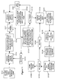
- FIG. 9 this illustrates the hard disk drive 168 in block diagram form so as to enable illustration of the programs and data provided by the embodiment of the invention and which are stored thereon. More particularly, there is first provided a control program 90, which acts when executed to control the overall operation of the system, to call and oversee the operation of the other programs, and to provide a user interface to allow a user to control the overall operation of the embodiment. Examples of the operations performed by the control program 90 are such things as allowing a user to enter the file name of an MPEG video sequence which is to be processed, decoding and displaying the MPEG sequence to the user and allowing the user to specify which parts of the sequence are to be created into a panorama. In addition, basic program control commands such as Start, Stop, Suspend, and the like are also provided by the control program 90 as part of the user interface to the system.
- basic program control commands such as Start, Stop, Suspend, and the like are also provided by the control program 90 as part of the user interface to the system.
- a global motion estimator program 92 which acts to take a video sequence as an input under the command of the control program 90, and to process the frames of the sequence so as to generate transformation parameters for each frame indicative of the global motion between each frame and its respective anchor frame. The transformation parameters may then be stored for each frame if necessary.
- the global motion estimator program may also be run under the control of a panoramic image generator program 94 (described next), to calculate transformation parameters for frames passed to the program from the panoramic image generator program.
- the panoramic image generator program 94 acts under the command of the control program 90 to take a video sequence as input (the sequence having been indicated to the control program 90 by a user), and to generate a panoramic image of the indicated sequence. It should be noted here that a single panoramic image can be generated for each sequence in which there is continuous motion, that is, for each individual "shot” or "edit” in the sequence. Each shot may contain multiple Groups of Pictures, and preferably each GoP ends with a B-frame to allow the global motion of the following I frame to be estimated. This is not essential, however, as where a GoP does not end with a B-frame the other techniques such as interpolation can be used to estimate a global motion estimation for the I-frame.
- the panoramic image generator program Once the panoramic image generator program has generated a panoramic image from the indicated sequence, the generated image is stored in a panoramic image data area 96 of the hard disk. The panoramic images may then be accessed and displayed by any suitable imaging applications as appropriate.
- the hard disk drive 168 also has an area 98 in which is stored the original MPEG video data in the form of MPEG files which are used as input to the system.
- the global motion estimator program 92 can be executed independently so as to simply produce global motion estimations for whatever use, or can be called by the panoramic image generator program 94 as part of its own operation. The following description assumes that the global motion estimator program has been launched independently.
- a human user would first use the control program 90 to select an MPEG video sequence for processing, and to command that it be subject to global motion estimation. Then, the control program 90 launches the global motion estimator program 92, and passes the program the MPEG encoded video sequence with an indication of for which frame or frames the global motion estimator program is to calculate the transformation parameters representative of the global motion in the indicated frame or frames. Where multiple frames are indicated, the global motion estimator program processes each frame in turn.
- the global motion estimator program 92 After receiving a frame as input, the global motion estimator program 92 then commences its processing at step 10.2, by decoding the motion vectors from the input frame. In the case of a P-frame there will only be forward motion vectors from the previous I-frame or P-frame. In the case of B-frames, there will be both forward and backward motion vectors, and both sets are decoded. Initially, however, only the set of forward motion vectors are used at first.
- step 10.4 the set of decoded motion vectors is subject to some filtering, in that those motion vectors with a zero value and those motion vectors located substantially at the boundaries of an image are removed.
- filtering for global motion estimation from MPEG video
- the reader is referred once again to the sets of typical motion vectors from a B-frame in a football video as shown in Figures 5 and 6 .
- these images are taken from a long distance and contain a dominant static ground-plane, most motion vectors reflect the global camera motion. However, a few motion vectors look different from the majority owing to the foreground object motion or MPEG encoding efficiency. These extraordinary motion vectors should be treated as outliers for global motion estimation.
- the outlier vectors are more likely to have large magnitudes, therefore may easily skew the solution from the desired one if they are not dealt with appropriately. Therefore, the vectors substantially at the boundaries of the image are removed, as these are more likely to be outlier vectors. With respect to the zero vectors, these are excluded as they usually do not specify a static macroblock in MPEG.
- step 10.6 the global motion estimator program acts to control the computer system to randomly select N sets of motion vectors, each set having 3 motion vectors therein. The reason for this step (and indeed for several of the subsequent steps) is as follows.
- MPEG motion vectors There are basically two types of motion in a video sequence: the global camera motion and the local object motion. Given a MPEG video clip with a dominant static background, most of the MPEG motion vectors may appear to reflect the global camera motion. Although these MPEG motion vectors are encoded on the purpose of video compression and may not be the "real" motion vectors, we would argue that, given a MPEG video with reasonable image and compression quality, the MPEG motion vectors are most likely to reflect the underlying motion in a video. Therefore it is possible to estimate the global motion from MPEG motion vectors.
- the whole video sequence can be warped to a reference frame, e.g. the first frame of the sequence, although other frames may also be used.
- the pixel value of x 0 in the first frame is taken as that of x n in the n-th frame.
- N log ⁇ 1 - p / log ⁇ 1 - 1 - ⁇ s
- p the probability of at least one of the N random samples is free from outliers
- ⁇ the expected proportion of outliers in the training data, i.e. the probability of a data point being an outlier
- s the sample size.
- the global motion estimator program controls the computer to randomly select 34 sets of motion vectors from the available motion vectors remaining after the filtering step of 10.4. Each set has three motion vectors, being the minimum sample size required to compute the affine transformation parameters representative of the global motion for the frame. It should be noted that in other embodiments N may be a different number, depending on the values set for p and ⁇ .
- the global motion estimator program controls the computer system to calculate the affine transformation for each of the N (in this case 34) sample sets, using the equations set out above.
- N in this case 34
- step 10.10 the program controls the computer to compute the median of squared error for each of the N transformations, and then next at step 10.12 the transformation with the smallest median value is selected as the transformation which is deemed representative of the global motion of the image. Subject to a test to be described next, this transformation is returned by the program as the global motion estimation for the particular frame being processed.
- the Least Median Squares (LmedS) method is very simple and does not need any prior knowledge of the problem.
- its main shortcoming is that when more than half of the training data are outliers, i.e. ⁇ > 50%, the data point with the median value may be an outlier, and therefore the returned transform parameters would not represent the true global motion of the frame.
- T the threshold
- various strategies may be employed to compute an alternative solution, as will be described later, suffice to say for the moment that if the median error is greater than the threshold then the transformation is discarded and the parameters are not output by the program.
- T 18, which means less than 3 pixel's displacement in both horizontal and vertical direction is acceptable (3 2 +3 2 ), proved to work fairly well in our experiments.
- T may take any value in an acceptable range of for example, 2 to 32, which represents a pixel displacement in the horizontal and vertical directions of between 1 and 4. This range may be extended further if a larger pixel displacement is acceptable.
- step 10.24 the selected transformation's parameters are returned as the output of the global motion estimator program, and the program then ends.
- processing proceeds to step 10.16, wherein an evaluation is made as to whether all the possible routes from the frame being processed back to the anchor frame for that frame have been processed.
- step 10.16 an evaluation is made as to whether all the possible routes from the frame being processed back to the anchor frame for that frame have been processed.
- step 10.18 and 10.20 are based on the inventors' realisation that the bi-directional nature of the motion vectors within the B-frames provide multiple global motion estimation routes from a frame back to its anchor frame, via one or more other frames.
- the motion vectors which directly relate the frame being processed to its anchor frame do not provide a transformation which meets the thresholding step described above, then the motion vectors between the frame being processed and another frame can be used to compute the relative global motion estimation between the frame being processed and the other frame, and then the motion vectors between the other frame and the original anchor frame can be used to compute a global motion estimation between the other frame and the anchor frame. Having obtained these two respective estimations, the estimations can be accumulated to give an overall estimation of the global motion between the original frame being processed and the anchor frame.
- an I-frame we first select its immediate preceding B-frame, and decode the backward motion vectors of this B-frame to estimate the global motion. If a failure is raised at step 10.14, we then select the second immediate preceding B-frame, and so on.
- the order is its preceding anchor frame, first immediate preceding B-frame, second immediate preceding B-frame and so on.
- a B-frame is usually directly warped to its preceding anchor frame, but may be warped to its succeeding anchor frame if this produces better results than the warping to the preceding frame.
- B-frames may also be warped via their succeeding anchor frames, and hence for any type of frame there are always multiple routes along which a global motion estimation may be found for the frame.
- I-frame in B 3 B 2 B 1 I order B 1 B 2 B 3 P-frame in IB 2 B 1 P, order IB 1 B 2 B-frames in IB 2 B 1 P, order IP
- Figures 12, to 16 demonstrate the situation of motion estimation along multiple routes.
- frame numbers 144-147 (IBBP) of a video sequence to produce a panoramic image.
- the forward motion vectors of frame 147 (P-frame) to the previous anchor frame (frame 144, I-frame) contain too many outliers for a reasonable estimation as shown in Figure 12
- the least median of squared error Med 791.8, meaning that the threshold at step 10.14 was exceeded. This meant that we could not warp the current frame to its previous anchor frame directly.
- both the backward and forward motion vectors in frame 146, its immediate preceding B-frame as shown in Figures 13 and 14 are sufficiently clean.
- step 10.16 if the evaluation at step 10.16 returns a negative then not all of the available routes from the frame being processed back to it's anchor frame have been processed, and processing proceeds to step 10.18, wherein the next available route is selected in accordance with the route ordering described previously. Then, at step 10.20 the entire process is repeated for each frame in the new route. That is, the entire process of steps 10.2 to 10.14 is repeated to find the global motion transformation between the original frame and another frame, and then repeated again to find the global motion transformation between the other frame and the original anchor frame. If during these iterations of the process the found transformations do not meet the threshold value, then another route is selected and processing repeats again for that route. Once a cumulative transformation has been found which meets the threshold, however, the parameters of that transformation are returned at step 10.24, and processing then ends.
- step 10.16 the evaluation at step 10.16 will return a positive result, and in such a case processing proceeds to step 10.22, where an interpolation is performed between the affine transformation parameters of adjacent frames to the frame being processed, to generate interpolated affine transformation parameters for the present frame. These interpolated affine transformation parameters are then output at step 10.24, and processing then ends.
- the operation of the global motion estimation program 92 can be summarised as follows: Coarse macroblock motion vectors can be extracted from MPEG video with a minimal decompression. With a reasonable MPEG encoder, most motion vectors may reflect the complex motion in a video scene although they are coded for compression purposes. Based on this idea, motion estimation from MPEG motion vectors can be formulated as a robust parameter estimation problem which treats the "good" motion vectors as inliers and "bad" ones outliers. The global motion estimation program 92 uses motion vectors in both P and B-frames of an MPEG video for global motion estimation.
- a Least Median of Squares based algorithm is adopted for robust motion estimation, but it is also recognised that the bi-directional information in B-frames provides multiple routes to warp a frame to its previous anchor frame. In the case of a large proportion of outliers, we detect possible algorithm failure and perform re-estimation along a different route. Where all available routes fail a motion estimation can be obtained through interpolation.
- the global motion estimation program 92 may be operated independently to simply find global motion estimations for other uses, or may be operated by the panoramic image generation program 92, as described next.
- Other uses of global motion estimations other than for producing panoramic images include moving-object image tracking applications, where in addition to the tracked object moving, the tracking image capture apparatus must also move. Global motion estimations can be useful here in compensating for the movement of the camera, in order to allow the true object movement to be found.
- the embodiment of the invention also provides the panoramic image generation program 94, and the operation of this program will be described next with respect to Figure 11 .
- the control program 90 launches the panoramic image generator program 94, and passes to the program the sequence of MPEG encoded video frames which the user has selected to be used to create the panoramic image.
- the panoramic image generator program 92 performs at step 11.2 is to set the first frame in the received sequence as a reference image. In other embodiments other frames in the sequence may be used as the reference frame.
- the plane of the first frame becomes a reference plane, which can be considered analogous to a "canvas" for a panoramic image onto which pixel values may be "painted". That is, the reference plane established by the first frame is also the plane of the panoramic image that is to be produced.
- a FOR processing loop is commenced, which acts to process every frame in the received video sequence according to the steps contained within the loop, and notably step 11.6.
- the panoramic image generator program 94 acts to launch the global motion estimator program 92, and passes to the estimator program 92 the frame presently being processed by the FOR loop, as well as the other frames in the video sequence.
- the global motion estimator program then operates as previously described to determine the transformation parameters for the present frame representative of the global motion of the frame, and these parameters are then passed back to the panoramic image generator program 94.
- step 11.7 an evaluation is undertaken to determine if all the frames in the sequence have been processed according to step 11.6, and if not at step 11.13 the next frame in the sequence is selected, and the FOR loop commences again for the next frame in the sequence.
- the FOR loop of steps 11.4, 11.6, 11.7, and 11.13 causes the global motion estimator program to determine global motion estimations for every frame in the sequence.
- step 111.7 returns positive, and processing proceeds to step 11.8, where a second FOR processing loop is started for each subsequent frame in the sequence other than the reference frame.
- This second FOR loop comprises steps 11.10 and 11.11. More particularly, at step 11.10 all of the determined affine transformations from the present frame being processed by the FOR loop back to the reference frame are accumulated, and then at step 11.11 the image of the present frame is warped onto the plane of the reference image using the accumulated affine transformations. The pixel values for each visible pixel of the frame are then stored for future use. It will be appreciated that where frames overlap due to the warping function there will be as many pixel values for a single pixel position on the reference plane as there are overlapping frames at that position.
- step 11.12 an evaluation is undertaken to determine if all the frames in the sequence have been processed according to steps 11.10 and 11.11, and if not at step 11.9 the next frame in the sequence is selected and steps 11.10 and 11.11 repeated in respect of that frame.
- the evaluation returns a positive result and processing proceeds to step 11.14.
- all of the frames in the sequence have been warped back to the reference plane. This has the practical effect that image registration between the frames is achieved, and the images within the frames are warped onto the plane of the reference frame. The processing has therefore reached the stage where panoramic images can be generated by selecting the appropriate pixel value to use for each pixel position.
- the content contained in a video sequence includes the static (background) and dynamic (foreground) information.
- static (background) and dynamic (foreground) information When constructing image panoramas from video sequences, it naturally leads to the concepts of background and foreground panoramas.
- foreground panoramas were constructed by taking the mismatched pixels (or groups of pixels) as foreground, and other pixels as background, but the embodiment of the invention uses a simpler and more efficient method to solve this problem.
- a pixel in the panoramic background is constructed from substantially the median of the pixels from all frames of a video sequence that are mapped to the same pixel position, while the foreground panorama is made up of substantially the most different pixel of the available pixels mapped to the same position. This is explained in more detail next.
- a further FOR processing loop is initiated, which acts to process every pixel position in the reference image, so as to find the pixel value from the available pixel values for each position which should be used in each of a foreground and a background panoramic image.
- the FOR loop comprises steps 11.16, 11.18. 11.20. and 11.22 as the main processing steps therein, and which embody the process described above, as described next.
- the equation (8) above is used to compute the mean pixel value for the particular pixel position being processed by the FOR loop of all of the available pixel values for that position.
- the mean pixel value would be found of those five frames.
- step 11.18 the L1 distance from the mean pixel value is found for each of the available pixel values for the present pixel position, using equation (9) above.
- Each L1 distance for each pixel is stored in an array, and once the distance has been found for each available pixel value, the array of L1 distance values is sorted into order.
- a pixel value for use at the present pixel position in a background panorama is selected by taking that pixel value with the median distance value in the sorted array. This is relatively straightforward where there are an odd number of distance values in the array, the median value being the (( n +1)/2)th distance value, where n is the number of distance values in the array.
- n /2th distance value may be taken as the median, or the ( n /2 + 1)th distance value, and this is a matter of design choice.
- a median pixel value may be obtained by interpolating between the pixel values respectively relating to the n /2th distance value and the ( n /2 + 1)th distance value.
- the pixel value is selected which has the maximum L1 distance of the available pixels (i.e. the largest distance value located at the end of the sorted array) for use at the present pixel position.
- step 11.24 an evaluation is undertaken to determine whether all the pixel positions necessary for the panoramic images (i.e. all the pixel positions in the reference image taking into the warping of the other frames thereto) have been processed, and respective foreground and background pixel values selected for each pixel position. If this evaluation returns negative then at step 11.26 the next pixel position is selected, and the procedure of steps 11.16, 11.18., 11.20, and 11.22 is repeated for this next pixel position. This process is repeated until all the pixel positions have had foreground and background pixel values selected therefor, whereupon the evaluation will then return a positive result.
- step 11.28 processing proceeds to step 11.28, wherein the pixel values selected for each pixel position in the foreground panorama are then written to a foreground panorama image file, and then the pixel values selected for each pixel position in the background panorama are then written to a background panorama image file.
- a foreground and a background panoramic image can be generated and stored by the panoramic image generator program 94 for each video sequence input thereto.
- the invention may be used to provide mosaic based video compression.
- the static scene can be represented efficiently using JPEG style compression techniques, and especially when a video contains a dominant static scene. Only the segmented foreground objects/activities, or even more simply, only the difference between a frame and its reference region in the panoramic scene, need to be coded. This should prove very useful for very low bit-rate transmission and video storage.
- the invention may also be used for mosaic based visualisation.
- the panoramic background and foreground images are used to provide a better understanding about both the static scene and the whole event that takes place in a video.
- a video sequence can be visualised as a set of "key frame mosaics", each encodes a continuous clip of the video. Obviously this is more representative than the conventional key frames.
- a further use is in video synthesis.
- the foreground activities as apparent from a foreground panorama can be extracted from a video against the panoramic background, the background panorama having been generated using the present invention. It is then possible to replace the background of the video with a different image therefore making the events in the video look as if they are taking place in another situation.
- Another use of the invention is as a virtual camera. While an original video may not be taken in the perfect camera set-up (e.g. camera jigging or over-zooming), the ability to warp images to a reference frame and to perform accurate image registration as provided by the invention can allow a video image to be re-constructed from an ideal "virtual view”.
- the perfect camera set-up e.g. camera jigging or over-zooming
- the ability to warp images to a reference frame and to perform accurate image registration as provided by the invention can allow a video image to be re-constructed from an ideal "virtual view”.
- the encoded video sequence being an MPEG encoded sequence, encoded according to any one of the MPEG standards. It is not, however, essential that the encoded video sequence be strictly MPEG encoded, as all that is required is an encoded video sequence which has been inter-frame encoded to produce motion vectors indicative of the general motion of a number of macroblocks which make up a frame with respect to a preceding or succeeding frame. Therefore, whilst the development of the invention has been based upon and is intended to encompass MPEG encoded video sequences, other video coding methods which provided the necessary motion vector information, but which may not be MPEG compliant may also be used to provide the encoded video sequence used by the invention.
Landscapes
- Engineering & Computer Science (AREA)
- Multimedia (AREA)
- Signal Processing (AREA)
- Compression Or Coding Systems Of Tv Signals (AREA)
- Image Analysis (AREA)
- Closed-Circuit Television Systems (AREA)
- Color Television Systems (AREA)
Claims (33)
- Verfahren zur globalen Bewegungsschätzung zwischen Einzelbildern einer bewegungskompensierten kodierten Zwischenrahmen-Videosequenz, wobei jedes Einzelbild der Sequenz mehrere in ihr kodierte Bewegungsvektoren aufweist, die das Einzelbild zu einem vorhergehenden und/oder darauffolgenden Einzelbild der Sequenz in Beziehung setzen; wobei das Verfahren für ein bestimmtes kodiertes Zwischenrahmen-Einzelbild umfasst:a) Dekodieren der Bewegungsvektoren des Einzelbilds (S.10.2);
gekennzeichnet durchb) Auswählen von N Sätzen von Bewegungsvektoren, wobei jeder Satz aus s ausgewählten Bewegungsvektoren des Einzelbilds umfasst ist, wobei N ein ganzzahliger Wert größer als 1 ist (S.10.6);c) Berechnen einer Bewegungsschätzung für jeden Satz (S.10.8);d) Berechnen eines Medianwerts des quadratischen Fehlerwerts für jede Bewegungsschätzung (S.10.10); unde) Auswählen der Bewegungsschätzung mit dem kleinsten Medianwert des quadratischen Fehlerwerts wie demjenigen, der die globale Bewegung des Einzelbilds in Bezug auf ein vorhergehendes oder darauffolgendes Ankereinzelbild darstellt (S.10.12). - Verfahren nach Anspruch 1, und weiterhin mit dem Schritt, bestimmte Bewegungsvektoren mit vorgegebenen Eigenschaften davon aufzuschließen, als Element eines der N Sätze ausgewählt zu werden.
- Verfahren nach Anspruch 2, wobei die ausgeschlossenen Bewegungsvektoren jene Bewegungsvektoren aus einem oder mehreren Bereichen im Wesentlichen rund um die Grenze des Einzelbilds einschließen.
- Verfahren nach Anspruch 2 oder 3, wobei die ausgeschlossenen Bewegungsvektoren jene Bewegungsvektoren einschließen, deren Wert im Wesentlichen Null ist.
- Verfahren nach irgendeinem der vorhergehenden Ansprüche, wobei der Auswahlschritt b) weiterhin das zufällige Auswählen von s Bewegungsvektoren aus den verfügbaren Bewegungsvektoren für jeden der N Sätze umfasst, wobei s die minimale Anzahl ist, um eine geometrische Umformung ausreichend abzuschätzen.
- Verfahren nach irgendeinem der vorhergehenden Ansprüche, und weiterhin mit den folgenden Schritten:c) Überprüfen der für die globale Bewegung stellvertretenden ausgewählten Bewegungsschätzung; undd) Ausgeben der ausgewählten Bewegungsschätzung als stellvertretend für die globale Bewegung des Einzelbilds, wenn die Überprüfung bestanden wird.
- Verfahren nach Anspruch 6, wobei die Überprüfung das Vergleichen der ausgewählten Bewegungsschätzung mit einem Schwellwert umfasst wobei die Überprüfung bestanden ist, wenn die Parameter den Schwellwert nicht überschreiten.
- Verfahren nach den Ansprüchen 6 oder 7, wobei, wenn die Überprüfung nicht bestanden wird, das Verfahren weiterhin umfasst:e) Bestimmen einer Bewegungsschätzung, die für die globale Bewegung des Einzelbilds in Bezug auf ein vorhergehendes oder darauffolgendes anderes Einzelbild stellvertretend ist;f) Bestimmen einer Bewegungsschätzung, die für die globale Bewegung des anderen Einzelbilds in Bezug auf das Ankereinzelbild stellvertretend ist; undg) Akkumulieren der Bewegungsschätzungen, um eine Gesamtbewegungsschätzung zu geben, die im Wesentlichen für die globale Bewegung des Einzelbilds in Bezug auf das Ankereinzelbild stellvertretend ist.
- Verfahren nach Anspruch 8, wobei die Bestimmungsschritte e) und f) jeweils ein Verfahren umfassen, das im Wesentlichen irgendeinem der vorhergehenden Ansprüche entspricht.
- Verfahren nach irgendeinem der Ansprüche 6 bis 9, wobei, wenn die Überprüfung nicht bestanden wird, das Verfahren weiterhin umfasst:Interpolieren zwischen den Bewegungsschätzungen nebeneinander liegender Einzelbilder, um eine interpolierte Bewegungsschätzung zu geben, die dann als die Bewegungsschätzung, die für die globale Bewegung des Einzelbilds stellvertretend ist, ausgegeben wird.
- Verfahren zum Erzeugen panoramischer Bilder aus einer bewegungskompensierten kodierten Zwischenrahmen-Videosequenz, mit:Bestimmen der globalen Bewegung jedes Einzelbilds in Bezug auf sein Ankerbild für jedes Einzelbild der Sequenz unter Anwendung des Verfahrens nach irgendeinem der vorhergehenden Ansprüche; undErzeugen zumindest eines panoramischen Bilds, das die Einzelbilder der Videosequenz darstellt, unter Verwendung der so bestimmten globalen Bewegungsschätzungen.
- Verfahren nach Anspruch 11, wobei der Erzeugungsschritt weiterhin umfasst:Auswählen eines bestimmten Einzelbilds der Sequenz als Bezugseinzelbild, wobei die Ebene des Bezugseinzelbilds eine Bezugsebene ist;Akkumulieren der globalen Bewegungsschätzungen von jedem Einzelbild zurück zum Bezugseinzelbild für jedes Einzelbild mit Ausnahme des Bezugseinzelbilds;Verformen jedes Einzelbilds mit Ausnahme des Bezugseinzelbilds auf die Bezugsebene unter Verwendung der akkumulierten globalen Bewegungsschätzungen, um einen oder mehrere Pixelwerte für jede Pixelposition in der Bezugsebene zu ergeben; undAuswählen eines der verfügbaren Pixelwerte zur Verwendung als der Pixelwert im panoramischen Bild für jede Pixelposition in der Bezugsebene.
- Verfahren nach Anspruch 12, wobei der Auswählschritt das Auswählen eines im Wesentlichen Medianwerts des Pixelwerts aus den verfügbaren Pixelwerten zur Verwendung in einem panoramischen Hintergrundbild umfasst.
- Verfahren nach den Ansprüchen 12 oder 13, wobei der Auswählschritt das Auswählen eines im Wesentlichen unterschiedlichsten Pixelwerts aus den verfügbaren Pixelwerten zur Verwendung in einem panoramischen Vordergrundbild umfasst.
- Verfahren nach irgendeinem der Ansprüche 12 bis 14, wobei der Auswählschritt umfasst:Berechnen des mittleren Pixelwerts der verfügbaren Pixelwerte,Berechnen des L1-Abstands zwischen jedem verfügbaren Pixelwert und dem berechneten mittleren Pixelwert; undAuswählen des Pixelwerts mit dem Medianwert des L1-Abstands zur Verwendung in einem panoramischen Hintergrundbild.
- Verfahren nach irgendeinem der Ansprüche 12 bis 15, wobei der Auswählschritt umfasst:Berechnen des mittleren Pixelwerts der verfügbaren Pixelwerte;Berechnen des L1-Abstands zwischen jedem verfügbaren Pixelwert und dem berechneten mittleren Pixelwert; undAuswählen des Pixelwerts mit dem maximalen L 1-Abstand zur Verwendung in einem panoramischen Vordergrundbild.
- System zur globalen Bewegungsschätzung zwischen Einzelbildern einer bewegungskompensierten kodierten Zwischenrahmen-Videosequenz, wobei jedes Einzelbild der Sequenz mehrere in ihr kodierte Bewegungsvektoren aufweist, die das Einzelbild zu einem vorhergehenden und/oder darauffolgenden Einzelbild der Sequenz in Beziehung setzen; wobei das System umfasst:a) einen Videodecoder, der dazu angeordnet ist, im Gebrauch die Bewegungsvektoren jedes kodierten Zwischenrahmen-Einzelbilds zu dekodieren;
dadurch gekennzeichnet, dass das System umfasstb) eine Videoverarbeitüngseinrichtung (92), die dazu angeordnet ist, im Gebrauch:i) N Sätze von Bewegungsvektoren auszuwählen, wobei jeder Satz aus s ausgewählten Bewegungsvektoren des Einzelbilds umfasst ist, wobei N ein ganzzahliger Wert größer als 1 ist;ii) eine Bewegungsschätzung für jeden Satz zu berechnen;iii) einen Medianwert des quadratischen Fehlerwerts für jede Bewegungsschätzung zu berechnen; undiv) die Bewegungsschätzung mit dem kleinsten Medianwert des quadratischen Fehlerwerts als denjenigen auszuwählen, der für die globale Bewegung des Einzelbilds in Bezug auf ein vorhergehendes oder darauffolgendes Ankereinzelbild stellvertretend ist. - System nach Anspruch 17, wobei die Videoverarbeitungseinrichtung weiterhin eine Bewegungsvektor-Ausschlusseinrichtung umfasst, um bestimmte Bewegungsvektoren mit vorgegebenen Eigenschaften davon aufzuschließen, als Element eines der N Sätze ausgewählt zu werden.
- System nach Anspruch 18, wobei die ausgeschlossenen Bewegungsvektoren jene Bewegungsvektoren von einem oder mehreren Bereichen im Wesentlichen rund um die Grenze des Bereichs einschießen.
- System nach den Ansprüchen 18 oder 19, wobei die ausgeschlossenen Bewegungsvektoren jene Bewegungsvektoren einschießen, deren Wert im Wesentlichen Null ist.
- System nach irgendeinem der Ansprüche 17 bis 20, wobei die Videoverarbeitungseinrichtung weiterhin dazu angeordnet ist, im Gebrauch:willkürlich s Bewegungsvektoren aus den verfügbaren Bewegungsvektoren für jeden der N Sätze auszuwählen, wobei s die minimale Anzahl ist, um eine geometrische Umformung ausreichend abzuschätzen.
- System nach irgendeinem der Ansprüche 17 bis 21, und weiterhin mit:c) einer Schätzprüfungseinrichtung, die dazu angeordnet ist, im Gebrauch die Bewegungsschätzung zu überprüfen, die als für die globale Bewegung stellvertretend ausgewählt ist; undd) einer Ausgabeeinrichtung zum Ausgeben der Bewegungsschätzung, die als stellvertretend für die globale Bewegung des Einzelbilds ausgewählt wird, wenn die Überprüfung bestanden ist.
- System nach Anspruch 22, wobei die Schätzprüfeinrichtung weiterhin dazu angeordnet ist, die Bewegungsschätzung mit einem Schwellwert zu vergleichen, wobei die Überprüfung bestanden ist, wenn die Bewegungsschätzung den Schwellwert nicht überschreitet.
- System nach den Ansprüchen 22 oder 23, wobei, wenn die Schätzprüfeinrichtung bestimmt, dass die Überprüfung nicht bestanden ist, die Videoverarbeitungseinrichtung weiterhin dazu angeordnet ist,v) eine Bewegungsschätzung zu bestimmen, die für die globale Bewegung des Einzelbilds in Bezug auf ein vorhergehendes oder darauffolgendes anderes Einzelbild stellvertretend ist;vi) eine Bewegungsschätzung zu bestimmen, die für die globale Bewegung des anderen Einzelbilds in Bezug auf das Ankereinzelbild stellvertretend ist; undvii) die Bewegungsschätzungen zu akkumulieren, um eine Gesamtbewegungsschätzung zu geben, die im Wesentlichen für die globale Bewegung des Einzelbilds in Bezug auf das Ankereinzelbild stellvertretend ist.
- System nach irgendeinem der Ansprüche 22 bis 24, und weiterhin mit:einer Schätzinterpolationseinrichtung, die dazu angeordnet ist, zwischen den Bewegungsschätzungen nebeneinander liegender Einzelbilder zu interpolieren, um eine interpolierte Bewegungsschätzung zu ergeben, die dann als die Bewegungsschätzung, die für die globale Bewegung des Einzelbilds stellvertretend ist, ausgegeben wird.
- System zum Erzeugen panoramischer Bilder aus einer bewegungskompensierten kodierten Zwischenrahmen-Videosequenz, mit:einem System zur globalen Bewegungsschätzung zwischen Einzelbildern einer bewegungskompensierten kodierten Zwischenrahmen-Videosequenz nach irgendeinem der Ansprüche 17 bis 25, und das weiterhin dazu angeordnet ist, globale Bewegungsschätzungen für jedes Einzelbild vorzusehen; undeiner Panoramabild-Erzeugungseinrichtung zum Erzeugen zumindest eines panoramischen Bilds, das die Einzelbilder der Videosequenz darstellt, unter Verwendung der so bestimmten globalen Bewegungsschätzungen.
- System nach Anspruch 26, wobei die Panoramabild-Erzeugungseinrichtung weiterhin dazu angeordnet ist, im Gebrauch:ein bestimmtes Einzelbild der Sequenz als Bezugseinzelbild auszuwählen, wobei die Ebene des Bezugseinzelbilds dadurch eine Bezugsebene ist;die globalen Bewegungsschätzungen von jedem Einzelbild zurück zum Bezugseinzelbild für jedes Einzelbild mit Ausnahme des Bezugseinzelbilds zu akkumulieren;jedes Einzelbild mit Ausnahme des Bezugseinzelbilds auf die Bezugsebene unter Verwendung der akkumulierten globalen Bewegungsschätzungen zu verformen, um einen oder mehrere Pixelwerte für jede Pixelposition in der Bezugsebene zu ergeben; undeines der verfügbaren Pixelwerte zur Verwendung als der Pixelwert im panoramischen Bild für jede Pixelposition in der Bezugsebene auszuwählen.
- System nach Anspruch 27, wobei die Panoramabild-Erzeugungseinrichtung weiterhin dazu angeordnet ist, einen im Wesentlichen Medianwert des Pixelwerts aus den verfügbaren Pixelwerten zur Verwendung in einem panoramischen Hintergrundbild auszuwählen.
- System nach den Ansprüchen 26 oder 27, wobei die Panoramabild-Erzeugungseinrichtung weiterhin dazu angeordnet ist, einen im Wesentlichen unterschiedlichsten Pixelwert aus den verfügbaren Pixelwerten zur Verwendung in einem panoramischen Vordergrundbild auszuwählen.
- System nach irgendeinem der Ansprüche 27 bis 29, wobei die Panoramabild-Erzeugungseinrichtung weiterhin dazu angeordnet ist:den mittleren Pixelwert der verfügbaren Pixelwerte zu berechnen,den L1-Abstand zwischen jedem verfügbaren Pixelwert und dem berechneten mittleren Pixelwert zu berechnen; undden Pixelwert mit dem Medianwert des L1-Abstands zur Verwendung in einem panoramischen Hintergrundbild auszuwählen.
- System nach irgendeinem der Ansprüche 27 bis 30, wobei die Panoramabild-Erzeugungseinrichtung weiterhin dazu angeordnet ist:den mittleren Pixelwert der verfügbaren Pixelwerte zu berechnen;den L1-Abstand zwischen jedem verfügbaren Pixelwert und dem berechneten mittleren Pixelwert zu berechnen; undden Pixelwert mit dem maximalen L1-Abstand zur Verwendung in einem panoramischen Vordergrundbild auszuwählen.
- Computerprogramm oder Folge von Programmen, die so angeordnet sind, dass das Programm oder die Folge von Programmen bei Ausführung auf einem Computersystem das Computersystem veranlasst, das Verfahren nach irgendeinem der vorhergehenden Ansprüche durchzuführen.
- Computerlesbares Speichermedium, das ein Computerprogramm oder eine Folge von Programmen nach Anspruch 32 speichert.
Applications Claiming Priority (3)
| Application Number | Priority Date | Filing Date | Title |
|---|---|---|---|
| GB0227570 | 2002-11-26 | ||
| GBGB0227570.9A GB0227570D0 (en) | 2002-11-26 | 2002-11-26 | Method and system for estimating global motion in video sequences |
| PCT/GB2003/005028 WO2004049721A1 (en) | 2002-11-26 | 2003-11-18 | Method and system for estimating global motion in video sequences |
Publications (2)
| Publication Number | Publication Date |
|---|---|
| EP1570676A1 EP1570676A1 (de) | 2005-09-07 |
| EP1570676B1 true EP1570676B1 (de) | 2012-01-04 |
Family
ID=9948538
Family Applications (1)
| Application Number | Title | Priority Date | Filing Date |
|---|---|---|---|
| EP03775589A Expired - Lifetime EP1570676B1 (de) | 2002-11-26 | 2003-11-18 | Verfahren und system zur schätzung der globalen bewegung in videosequenzen |
Country Status (6)
| Country | Link |
|---|---|
| US (1) | US8494051B2 (de) |
| EP (1) | EP1570676B1 (de) |
| AT (1) | ATE540530T1 (de) |
| CA (1) | CA2505624C (de) |
| GB (1) | GB0227570D0 (de) |
| WO (1) | WO2004049721A1 (de) |
Families Citing this family (32)
| Publication number | Priority date | Publication date | Assignee | Title |
|---|---|---|---|---|
| GB0227566D0 (en) | 2002-11-26 | 2002-12-31 | British Telecomm | Method and system for estimating global motion in video sequences |
| US7684628B2 (en) * | 2004-08-12 | 2010-03-23 | Industrial Technology Research Institute | System and method for non-iterative global motion estimation |
| EP1779672A4 (de) * | 2004-08-13 | 2010-10-27 | Ind Academic Coop | Verfahren und vorrichtung zur bewegungsschätzung und kompensation für panoramabild |
| US7471336B2 (en) * | 2005-02-18 | 2008-12-30 | Genesis Microchip Inc. | Global motion adaptive system with motion values correction with respect to luminance level |
| EP1703736A1 (de) * | 2005-03-14 | 2006-09-20 | BRITISH TELECOMMUNICATIONS public limited company | Globale Bewegungsschätzung |
| JP5423948B2 (ja) * | 2006-03-09 | 2014-02-19 | 日本電気株式会社 | 動画像符号化方法、およびこれを用いた装置とプログラム |
| WO2007122584A1 (en) * | 2006-04-24 | 2007-11-01 | Nxp B.V. | Method and device for generating a panoramic image from a video sequence |
| US8139026B2 (en) | 2006-08-02 | 2012-03-20 | Research In Motion Limited | System and method for adjusting presentation of text and images on an electronic device according to an orientation of the device |
| US8493323B2 (en) | 2006-08-02 | 2013-07-23 | Research In Motion Limited | System and method for adjusting presentation of moving images on an electronic device according to an orientation of the device |
| KR100832872B1 (ko) | 2006-12-28 | 2008-05-28 | 충북대학교 산학협력단 | 기하학적 변환을 이용한 영상 부호화 효율 향상 방법 및장치 |
| JP2008219428A (ja) * | 2007-03-02 | 2008-09-18 | Fujifilm Corp | 撮像装置 |
| KR101366242B1 (ko) * | 2007-03-29 | 2014-02-20 | 삼성전자주식회사 | 움직임 모델 파라메터의 부호화, 복호화 방법 및 움직임모델 파라메터를 이용한 영상의 부호화, 복호화 방법 및장치 |
| JP2009077362A (ja) * | 2007-08-24 | 2009-04-09 | Sony Corp | 画像処理装置、動画再生装置、これらにおける処理方法およびプログラム |
| KR101003105B1 (ko) * | 2008-01-29 | 2010-12-21 | 한국전자통신연구원 | 어파인 변환 기반의 움직임 보상을 이용한 비디오 부호화 및 복호화 방법 및 장치 |
| JP4764487B2 (ja) * | 2009-03-02 | 2011-09-07 | 株式会社日立製作所 | 映像監視システム |
| US8301697B2 (en) * | 2009-06-16 | 2012-10-30 | Microsoft Corporation | Adaptive streaming of conference media and data |
| CN102714719A (zh) * | 2010-01-13 | 2012-10-03 | 英特尔公司 | 容错的视频传输方案 |
| US8824554B2 (en) * | 2010-09-02 | 2014-09-02 | Intersil Americas LLC | Systems and methods for video content analysis |
| JP2012191486A (ja) * | 2011-03-11 | 2012-10-04 | Sony Corp | 画像合成装置と画像合成方法およびプログラム |
| WO2014133559A1 (en) * | 2013-02-27 | 2014-09-04 | Blendagram, Inc. | System for and method of augmenting video and images |
| KR102121558B1 (ko) | 2013-03-15 | 2020-06-10 | 삼성전자주식회사 | 비디오 이미지의 안정화 방법, 후처리 장치 및 이를 포함하는 비디오 디코더 |
| TWI489415B (zh) * | 2013-07-17 | 2015-06-21 | Vivotek Inc | 視訊處理方法及系統 |
| KR20170025058A (ko) * | 2015-08-27 | 2017-03-08 | 삼성전자주식회사 | 영상 처리 장치 및 이를 포함하는 전자 시스템 |
| EP3364655A4 (de) | 2015-11-11 | 2018-10-10 | Samsung Electronics Co., Ltd. | Verfahren und vorrichtung zur videodecodierung sowie verfahren und vorrichtung zur videocodierung |
| KR101698314B1 (ko) * | 2015-12-09 | 2017-01-20 | 경북대학교 산학협력단 | 영상 통계정보에 기반한 정지장면 분할장치 및 그 방법 |
| CN109040575B (zh) * | 2017-06-09 | 2020-12-08 | 株式会社理光 | 全景视频的处理方法、装置、设备、计算机可读存储介质 |
| CN109547789B (zh) * | 2019-01-11 | 2022-11-04 | 重庆理工大学 | 一种全局运动补偿算法 |
| JP7093015B2 (ja) * | 2019-04-24 | 2022-06-29 | 日本電信電話株式会社 | パノラマ映像合成装置、パノラマ映像合成方法、及びパノラマ映像合成プログラム |
| CN111369592B (zh) * | 2020-03-13 | 2023-07-25 | 浙江工业大学 | 一种基于牛顿插值的快速全局运动估计方法 |
| CN113411581B (zh) * | 2021-06-28 | 2022-08-05 | 展讯通信(上海)有限公司 | 视频序列的运动补偿方法、系统、存储介质及终端 |
| CN115439926B (zh) * | 2022-08-05 | 2026-01-02 | 武汉大学 | 一种基于关键区域和场景深度的小样本异常行为识别方法 |
| CN120355821B (zh) * | 2025-03-19 | 2025-10-24 | 广东量子起源科技有限公司 | 一种三维虚拟动画设计交互系统 |
Family Cites Families (20)
| Publication number | Priority date | Publication date | Assignee | Title |
|---|---|---|---|---|
| US5473379A (en) | 1993-11-04 | 1995-12-05 | At&T Corp. | Method and apparatus for improving motion compensation in digital video coding |
| DE4405803C2 (de) * | 1994-02-23 | 1997-04-30 | Bosch Gmbh Robert | Verfahren zur Quellcodierung |
| KR0148154B1 (ko) | 1994-06-15 | 1998-09-15 | 김광호 | 움직임크기에 따른 동영상데이타의 부호화방법 및 장치 |
| KR100207390B1 (ko) * | 1995-09-15 | 1999-07-15 | 전주범 | 계층적인 움직임 추정기법을 이용하는 음직임 벡터 검출방법 |
| US5640822A (en) * | 1995-10-02 | 1997-06-24 | Mastercraft Engineering | Truss anchor |
| JPH10191360A (ja) | 1996-08-22 | 1998-07-21 | Cirrus Logic Inc | 動き推定ベクトルを求める方法および動き推定ベクトルを用いて動画像データを圧縮する方法 |
| US6047078A (en) | 1997-10-03 | 2000-04-04 | Digital Equipment Corporation | Method for extracting a three-dimensional model using appearance-based constrained structure from motion |
| US6275527B1 (en) * | 1998-01-14 | 2001-08-14 | Conexant Systems, Inc. | Pre-quantization in motion compensated video coding |
| US6348918B1 (en) * | 1998-03-20 | 2002-02-19 | Microsoft Corporation | Stereo reconstruction employing a layered approach |
| US6646687B1 (en) | 1999-04-16 | 2003-11-11 | Ultimatte Corporation | Automatic background scene defocusing for image compositing |
| CN1166213C (zh) * | 1999-04-30 | 2004-09-08 | 皇家菲利浦电子有限公司 | 选择b帧编码模式的视频编码方法和系统 |
| DE69942157D1 (de) * | 1999-05-13 | 2010-04-29 | St Microelectronics Asia | Adaptiver bewegungsschätzer |
| GB9920256D0 (en) * | 1999-08-26 | 1999-10-27 | Wave Limited M | Motion estimation and compensation in video compression |
| US6977664B1 (en) * | 1999-09-24 | 2005-12-20 | Nippon Telegraph And Telephone Corporation | Method for separating background sprite and foreground object and method for extracting segmentation mask and the apparatus |
| US7084877B1 (en) | 2000-06-06 | 2006-08-01 | General Instrument Corporation | Global motion estimation for sprite generation |
| US7227896B2 (en) * | 2001-10-04 | 2007-06-05 | Sharp Laboratories Of America, Inc. | Method and apparatus for global motion estimation |
| KR100412501B1 (ko) * | 2001-11-30 | 2003-12-31 | 삼성전자주식회사 | 움직임 보상을 위한 화소값 선택 장치 및 방법 |
| US7023921B2 (en) * | 2002-08-06 | 2006-04-04 | Motorola, Inc. | Method and apparatus for determining block match quality |
| GB0227566D0 (en) * | 2002-11-26 | 2002-12-31 | British Telecomm | Method and system for estimating global motion in video sequences |
| GB0227565D0 (en) * | 2002-11-26 | 2002-12-31 | British Telecomm | Method and system for generating panoramic images from video sequences |
-
2002
- 2002-11-26 GB GBGB0227570.9A patent/GB0227570D0/en not_active Ceased
-
2003
- 2003-11-18 CA CA2505624A patent/CA2505624C/en not_active Expired - Lifetime
- 2003-11-18 AT AT03775589T patent/ATE540530T1/de active
- 2003-11-18 EP EP03775589A patent/EP1570676B1/de not_active Expired - Lifetime
- 2003-11-18 WO PCT/GB2003/005028 patent/WO2004049721A1/en not_active Ceased
- 2003-11-18 US US10/535,621 patent/US8494051B2/en active Active
Also Published As
| Publication number | Publication date |
|---|---|
| EP1570676A1 (de) | 2005-09-07 |
| US20060072663A1 (en) | 2006-04-06 |
| WO2004049721A1 (en) | 2004-06-10 |
| ATE540530T1 (de) | 2012-01-15 |
| US8494051B2 (en) | 2013-07-23 |
| GB0227570D0 (en) | 2002-12-31 |
| CA2505624C (en) | 2014-08-12 |
| CA2505624A1 (en) | 2004-06-10 |
Similar Documents
| Publication | Publication Date | Title |
|---|---|---|
| US8494051B2 (en) | Method and system for estimating global motion in video sequences | |
| US20060062296A1 (en) | Method and system for generating panoramic images from video sequences | |
| EP1565886B1 (de) | Verfahren und anordnung zur schätzung globaler bewegung in videosequenzen | |
| Liu et al. | Codingflow: Enable video coding for video stabilization | |
| JP4666784B2 (ja) | ビデオシーケンスのキーフレーム抽出方法及びビデオシーケンスのキーフレーム抽出装置 | |
| US20040126021A1 (en) | Rapid production of reduced-size images from compressed video streams | |
| US20080279280A1 (en) | Moving picture decoding integrated circuit | |
| JP2001527304A (ja) | ディジタル動画の階層的要約及び閲覧方法 | |
| JP2001313956A (ja) | Mpeg圧縮ビデオ環境における階層的混合型ショット変換検出方法 | |
| US5416522A (en) | Motion detection apparatus for moving pictures and encoding and decoding apparatus for picture signals | |
| US20090060359A1 (en) | Method and apparatus for estimating and compensating spatiotemporal motion of image | |
| Chen et al. | Extraction of high-resolution video stills from MPEG image sequences | |
| JP2001526859A (ja) | ワールドワイドウェブ上の圧縮映像の指示及び編集方法及びアーキテクチュア | |
| Yeo | Efficient processing of compressed images and video | |
| US20050123039A1 (en) | Motion estimation method for motion picture encoding and recording medium having program recorded thereon to implement the motion estimation method | |
| US20130028330A1 (en) | Methods and Apparatus for Reducing Vector Quantization Error Through Patch Shifting | |
| US7526725B2 (en) | Context aware video conversion method and playback system | |
| Li et al. | Robust panorama from mpeg video | |
| JP2002514861A (ja) | Mpeg符号化信号のトリックプレイ再生 | |
| US20090080529A1 (en) | Image encoding apparatus, method of controlling therefor, and program | |
| Robertson et al. | Mosaics from MPEG-2 video | |
| Li et al. | A robust, efficient, and fast global motion estimation method from MPEG compressed video | |
| Morimoto et al. | Video coding using hybrid motion compensation | |
| CN1174633C (zh) | 运动画面压缩电路及使用运动矢量的方法 | |
| Zheng et al. | Video error concealment based on implicit motion models |
Legal Events
| Date | Code | Title | Description |
|---|---|---|---|
| PUAI | Public reference made under article 153(3) epc to a published international application that has entered the european phase |
Free format text: ORIGINAL CODE: 0009012 |
|
| 17P | Request for examination filed |
Effective date: 20050502 |
|
| AK | Designated contracting states |
Kind code of ref document: A1 Designated state(s): AT BE BG CH CY CZ DE DK EE ES FI FR GB GR HU IE IT LI LU MC NL PT RO SE SI SK TR |
|
| AX | Request for extension of the european patent |
Extension state: AL LT LV MK |
|
| DAX | Request for extension of the european patent (deleted) | ||
| 17Q | First examination report despatched |
Effective date: 20060622 |
|
| GRAP | Despatch of communication of intention to grant a patent |
Free format text: ORIGINAL CODE: EPIDOSNIGR1 |
|
| RIC1 | Information provided on ipc code assigned before grant |
Ipc: H04N 7/26 20060101AFI20110705BHEP Ipc: G06T 7/20 20060101ALI20110705BHEP Ipc: G06T 3/00 20060101ALI20110705BHEP |
|
| GRAS | Grant fee paid |
Free format text: ORIGINAL CODE: EPIDOSNIGR3 |
|
| GRAA | (expected) grant |
Free format text: ORIGINAL CODE: 0009210 |
|
| AK | Designated contracting states |
Kind code of ref document: B1 Designated state(s): AT BE BG CH CY CZ DE DK EE ES FI FR GB GR HU IE IT LI LU MC NL PT RO SE SI SK TR |
|
| REG | Reference to a national code |
Ref country code: GB Ref legal event code: FG4D |
|
| REG | Reference to a national code |
Ref country code: CH Ref legal event code: EP |
|
| REG | Reference to a national code |
Ref country code: AT Ref legal event code: REF Ref document number: 540530 Country of ref document: AT Kind code of ref document: T Effective date: 20120115 |
|
| REG | Reference to a national code |
Ref country code: IE Ref legal event code: FG4D |
|
| REG | Reference to a national code |
Ref country code: DE Ref legal event code: R096 Ref document number: 60339618 Country of ref document: DE Effective date: 20120308 |
|
| REG | Reference to a national code |
Ref country code: NL Ref legal event code: VDEP Effective date: 20120104 |
|
| PG25 | Lapsed in a contracting state [announced via postgrant information from national office to epo] |
Ref country code: SI Free format text: LAPSE BECAUSE OF FAILURE TO SUBMIT A TRANSLATION OF THE DESCRIPTION OR TO PAY THE FEE WITHIN THE PRESCRIBED TIME-LIMIT Effective date: 20120104 |
|
| PG25 | Lapsed in a contracting state [announced via postgrant information from national office to epo] |
Ref country code: BG Free format text: LAPSE BECAUSE OF FAILURE TO SUBMIT A TRANSLATION OF THE DESCRIPTION OR TO PAY THE FEE WITHIN THE PRESCRIBED TIME-LIMIT Effective date: 20120404 Ref country code: NL Free format text: LAPSE BECAUSE OF FAILURE TO SUBMIT A TRANSLATION OF THE DESCRIPTION OR TO PAY THE FEE WITHIN THE PRESCRIBED TIME-LIMIT Effective date: 20120104 Ref country code: BE Free format text: LAPSE BECAUSE OF FAILURE TO SUBMIT A TRANSLATION OF THE DESCRIPTION OR TO PAY THE FEE WITHIN THE PRESCRIBED TIME-LIMIT Effective date: 20120104 |
|
| PG25 | Lapsed in a contracting state [announced via postgrant information from national office to epo] |
Ref country code: PT Free format text: LAPSE BECAUSE OF FAILURE TO SUBMIT A TRANSLATION OF THE DESCRIPTION OR TO PAY THE FEE WITHIN THE PRESCRIBED TIME-LIMIT Effective date: 20120504 Ref country code: GR Free format text: LAPSE BECAUSE OF FAILURE TO SUBMIT A TRANSLATION OF THE DESCRIPTION OR TO PAY THE FEE WITHIN THE PRESCRIBED TIME-LIMIT Effective date: 20120405 Ref country code: FI Free format text: LAPSE BECAUSE OF FAILURE TO SUBMIT A TRANSLATION OF THE DESCRIPTION OR TO PAY THE FEE WITHIN THE PRESCRIBED TIME-LIMIT Effective date: 20120104 |
|
| REG | Reference to a national code |
Ref country code: AT Ref legal event code: MK05 Ref document number: 540530 Country of ref document: AT Kind code of ref document: T Effective date: 20120104 |
|
| PG25 | Lapsed in a contracting state [announced via postgrant information from national office to epo] |
Ref country code: CY Free format text: LAPSE BECAUSE OF FAILURE TO SUBMIT A TRANSLATION OF THE DESCRIPTION OR TO PAY THE FEE WITHIN THE PRESCRIBED TIME-LIMIT Effective date: 20120104 |
|
| PG25 | Lapsed in a contracting state [announced via postgrant information from national office to epo] |
Ref country code: EE Free format text: LAPSE BECAUSE OF FAILURE TO SUBMIT A TRANSLATION OF THE DESCRIPTION OR TO PAY THE FEE WITHIN THE PRESCRIBED TIME-LIMIT Effective date: 20120104 Ref country code: RO Free format text: LAPSE BECAUSE OF FAILURE TO SUBMIT A TRANSLATION OF THE DESCRIPTION OR TO PAY THE FEE WITHIN THE PRESCRIBED TIME-LIMIT Effective date: 20120104 Ref country code: DK Free format text: LAPSE BECAUSE OF FAILURE TO SUBMIT A TRANSLATION OF THE DESCRIPTION OR TO PAY THE FEE WITHIN THE PRESCRIBED TIME-LIMIT Effective date: 20120104 Ref country code: SE Free format text: LAPSE BECAUSE OF FAILURE TO SUBMIT A TRANSLATION OF THE DESCRIPTION OR TO PAY THE FEE WITHIN THE PRESCRIBED TIME-LIMIT Effective date: 20120104 Ref country code: CZ Free format text: LAPSE BECAUSE OF FAILURE TO SUBMIT A TRANSLATION OF THE DESCRIPTION OR TO PAY THE FEE WITHIN THE PRESCRIBED TIME-LIMIT Effective date: 20120104 |
|
| PLBE | No opposition filed within time limit |
Free format text: ORIGINAL CODE: 0009261 |
|
| STAA | Information on the status of an ep patent application or granted ep patent |
Free format text: STATUS: NO OPPOSITION FILED WITHIN TIME LIMIT |
|
| PG25 | Lapsed in a contracting state [announced via postgrant information from national office to epo] |
Ref country code: SK Free format text: LAPSE BECAUSE OF FAILURE TO SUBMIT A TRANSLATION OF THE DESCRIPTION OR TO PAY THE FEE WITHIN THE PRESCRIBED TIME-LIMIT Effective date: 20120104 Ref country code: IT Free format text: LAPSE BECAUSE OF FAILURE TO SUBMIT A TRANSLATION OF THE DESCRIPTION OR TO PAY THE FEE WITHIN THE PRESCRIBED TIME-LIMIT Effective date: 20120104 |
|
| 26N | No opposition filed |
Effective date: 20121005 |
|
| PG25 | Lapsed in a contracting state [announced via postgrant information from national office to epo] |
Ref country code: AT Free format text: LAPSE BECAUSE OF FAILURE TO SUBMIT A TRANSLATION OF THE DESCRIPTION OR TO PAY THE FEE WITHIN THE PRESCRIBED TIME-LIMIT Effective date: 20120104 |
|
| REG | Reference to a national code |
Ref country code: DE Ref legal event code: R097 Ref document number: 60339618 Country of ref document: DE Effective date: 20121005 |
|
| PG25 | Lapsed in a contracting state [announced via postgrant information from national office to epo] |
Ref country code: ES Free format text: LAPSE BECAUSE OF FAILURE TO SUBMIT A TRANSLATION OF THE DESCRIPTION OR TO PAY THE FEE WITHIN THE PRESCRIBED TIME-LIMIT Effective date: 20120415 |
|
| REG | Reference to a national code |
Ref country code: CH Ref legal event code: PL |
|
| PG25 | Lapsed in a contracting state [announced via postgrant information from national office to epo] |
Ref country code: CH Free format text: LAPSE BECAUSE OF NON-PAYMENT OF DUE FEES Effective date: 20121130 Ref country code: LI Free format text: LAPSE BECAUSE OF NON-PAYMENT OF DUE FEES Effective date: 20121130 |
|
| REG | Reference to a national code |
Ref country code: IE Ref legal event code: MM4A |
|
| PG25 | Lapsed in a contracting state [announced via postgrant information from national office to epo] |
Ref country code: IE Free format text: LAPSE BECAUSE OF NON-PAYMENT OF DUE FEES Effective date: 20121118 |
|
| PG25 | Lapsed in a contracting state [announced via postgrant information from national office to epo] |
Ref country code: TR Free format text: LAPSE BECAUSE OF FAILURE TO SUBMIT A TRANSLATION OF THE DESCRIPTION OR TO PAY THE FEE WITHIN THE PRESCRIBED TIME-LIMIT Effective date: 20120104 Ref country code: MC Free format text: LAPSE BECAUSE OF NON-PAYMENT OF DUE FEES Effective date: 20121130 |
|
| PG25 | Lapsed in a contracting state [announced via postgrant information from national office to epo] |
Ref country code: LU Free format text: LAPSE BECAUSE OF NON-PAYMENT OF DUE FEES Effective date: 20121118 |
|
| PG25 | Lapsed in a contracting state [announced via postgrant information from national office to epo] |
Ref country code: HU Free format text: LAPSE BECAUSE OF FAILURE TO SUBMIT A TRANSLATION OF THE DESCRIPTION OR TO PAY THE FEE WITHIN THE PRESCRIBED TIME-LIMIT Effective date: 20031118 |
|
| REG | Reference to a national code |
Ref country code: FR Ref legal event code: PLFP Year of fee payment: 13 |
|
| REG | Reference to a national code |
Ref country code: FR Ref legal event code: PLFP Year of fee payment: 14 |
|
| REG | Reference to a national code |
Ref country code: FR Ref legal event code: PLFP Year of fee payment: 15 |
|
| PGFP | Annual fee paid to national office [announced via postgrant information from national office to epo] |
Ref country code: FR Payment date: 20221021 Year of fee payment: 20 |
|
| PGFP | Annual fee paid to national office [announced via postgrant information from national office to epo] |
Ref country code: GB Payment date: 20221021 Year of fee payment: 20 Ref country code: DE Payment date: 20221020 Year of fee payment: 20 |
|
| REG | Reference to a national code |
Ref country code: DE Ref legal event code: R071 Ref document number: 60339618 Country of ref document: DE |
|
| REG | Reference to a national code |
Ref country code: GB Ref legal event code: PE20 Expiry date: 20231117 |
|
| PG25 | Lapsed in a contracting state [announced via postgrant information from national office to epo] |
Ref country code: GB Free format text: LAPSE BECAUSE OF EXPIRATION OF PROTECTION Effective date: 20231117 |
|
| PG25 | Lapsed in a contracting state [announced via postgrant information from national office to epo] |
Ref country code: GB Free format text: LAPSE BECAUSE OF EXPIRATION OF PROTECTION Effective date: 20231117 |