EP1570586B1 - Method and apparatus to control transmission power and transmssion rate of an air link - Google Patents
Method and apparatus to control transmission power and transmssion rate of an air link Download PDFInfo
- Publication number
- EP1570586B1 EP1570586B1 EP03786897A EP03786897A EP1570586B1 EP 1570586 B1 EP1570586 B1 EP 1570586B1 EP 03786897 A EP03786897 A EP 03786897A EP 03786897 A EP03786897 A EP 03786897A EP 1570586 B1 EP1570586 B1 EP 1570586B1
- Authority
- EP
- European Patent Office
- Prior art keywords
- value
- power level
- data transmission
- link margin
- transmission power
- Prior art date
- Legal status (The legal status is an assumption and is not a legal conclusion. Google has not performed a legal analysis and makes no representation as to the accuracy of the status listed.)
- Expired - Lifetime
Links
Images

Classifications
-
- H—ELECTRICITY
- H04—ELECTRIC COMMUNICATION TECHNIQUE
- H04W—WIRELESS COMMUNICATION NETWORKS
- H04W52/00—Power management, e.g. Transmission Power Control [TPC] or power classes
- H04W52/04—Transmission power control [TPC]
- H04W52/18—TPC being performed according to specific parameters
- H04W52/26—TPC being performed according to specific parameters using transmission rate or quality of service QoS [Quality of Service]
- H04W52/267—TPC being performed according to specific parameters using transmission rate or quality of service QoS [Quality of Service] taking into account the information rate
-
- H—ELECTRICITY
- H04—ELECTRIC COMMUNICATION TECHNIQUE
- H04L—TRANSMISSION OF DIGITAL INFORMATION, e.g. TELEGRAPHIC COMMUNICATION
- H04L1/00—Arrangements for detecting or preventing errors in the information received
- H04L1/0001—Systems modifying transmission characteristics according to link quality, e.g. power backoff
- H04L1/0002—Systems modifying transmission characteristics according to link quality, e.g. power backoff by adapting the transmission rate
-
- H—ELECTRICITY
- H04—ELECTRIC COMMUNICATION TECHNIQUE
- H04W—WIRELESS COMMUNICATION NETWORKS
- H04W52/00—Power management, e.g. Transmission Power Control [TPC] or power classes
- H04W52/04—Transmission power control [TPC]
- H04W52/38—TPC being performed in particular situations
- H04W52/50—TPC being performed in particular situations at the moment of starting communication in a multiple access environment
Definitions
- radio transmitters may transmit at a fixed power level. Transmission at a fixed power level may become excessive when the communication distance between a mobile unit (MU) and an access point (AP) may be reduced. Furthermore, when the communication distance between MU and AP is increased, the transmission signal may be too weak. Thus, transmission data rate may be reduced.
- MU mobile unit
- AP access point
- One way to overcome the above-described disadvantage may be to adjust the transmission power level by using a close loop power control.
- the transmission power level from, for example, an AP may be obtained by exchanging messages between the AP and the MU.
- WLAN standards such as, for example "IEEE 802.11b, 1999 Edition", neither address power control issue nor provide enough information to the MU to utilize the close loop power control method.
- US 2002/0036994 discusses a method for determining a forward data rate and a forward transmission power level in a mobile communication system.
- An access terminal measures a C/I of a forward pilot channel, determines a forward data rate by matching the measured C/I with a reference C/I, creates a difference between the measured C/I and the reference C/I as margin information, and transmits the determined forward data rate and margin information over a reverse transmission channel.
- an access network Upon receipt of the forward data rate and margin information, an access network decreases a transmission power level by power corresponding to the margin information and performs forward transmission at the forward data rate at the decreased transmission power level.
- EP 1207644 discusses a method of link adaptation or a blind type using power offset and multi-codes transmission etc. through acknowledgements (ACK/NAK) in an ARQ System having a Hybrid type as a link adaptation method.
- ACK/NAK acknowledgements
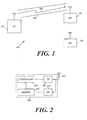
- FIG. 1 is a schematic illustration of a portion of a WLAN communication system according to an exemplary embodiment of the present invention
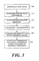
- FIG. 2 is a schematic block diagram of a WLAN transceiver according to exemplary embodiments of the present invention
- FIG. 3 is a schematic flowchart of a method to control transmission according to exemplary embodiments of the present invention.
- FIG. 4 is a schematic flowchart of an iterative method of setting transmission values according to an exemplary embodiment of the present invention.
- the present invention may be used in a variety of applications. Although the present invention is not limited in this respect, the circuits and techniques disclosed herein may be used in many apparatuses such as transmitters of a radio system. Transmitters intended to be included within the scope of the present invention include, by way of example only, wireless local area network (WLAN) transmitters, two-way radio transmitters, digital system transmitters, analog system transmitters, cellular radiotelephone transmitters and the like.
- WLAN wireless local area network
- Types of WLAN transmitters intended to be within the scope of the present invention include, although are not limited to, transmitters for transmitting spread spectrum signals such as, for example.
- FHSS Frequency Hopping Spread Spectrum
- DSSS Direct Sequence Spread Spectrum
- WLAN network 100 may include an access point (AP) 110 and mobile units 120 and 130, although the scope of the present invention is not limited to this example.
- AP 110 may transmit a beacon 150, which may include a broadcast message containing system information, to be received by MU 120.
- Beacon 150 may be transmitted over an air link 140 using a predetermined data transfer rate, such as, for example, 1 Mega bits per second (Mbps), which may be the lowest transmission rate according to a WLAN standard.
- a predetermined data transfer rate such as, for example, 1 Mega bits per second (Mbps), which may be the lowest transmission rate according to a WLAN standard.
- the AP 110 and MU's 120, 130 of WLAN 100 may comply with transmission standards, e.g., "IEEE-Std 802.11, 1999 Edition” standard and/or “IEEE-Std 803.11a, 1999 Edition for 5 Giga Hertz (GHz) frequency band” standard and/or “IEEE-Std 803.11b, 1999 Edition for 2.4 GHz frequency band” standard, as are known in the art.
- transmission standards e.g., "IEEE-Std 802.11, 1999 Edition” standard and/or “IEEE-Std 803.11a, 1999 Edition for 5 Giga Hertz (GHz) frequency band” standard and/or “IEEE-Std 803.11b, 1999 Edition for 2.4 GHz frequency band” standard, as are known in the art.
- mobile unit 200 may include an antenna 210, a transmitter (TX) 220, a receiver (RX) 23 0, a controller 240 and a memory 250.
- TX transmitter
- RX receiver
- antenna 210 for example, a dipole antenna, a shot antenna, or any other suitable type of antenna, may receive a signal from AP 110.
- the received signal which may include beacon 150 may contain information representing transmission data such as, for example, a data rate value, e.g., 1Mbps, and/or other data, such as control messages and the like.
- Receiver 230 may receive beacon 150 and may provide the data rate value to controller 240. Additionally or alternatively, controller 240 may measure a received signal strength (RSS) value of receiver 230 based on received broadcast messages.
- RSS received signal strength
- receiver 230 may include a receiver that is able to receive and demodulate spread spectrum signals that may be in use in the WLAN system, if desired.
- Memory 250 stores values related to the sensitivity of receiver 230.
- the receiver sensitivity values may be arranged in a table and are selected by controller 240 based on the data rate value.
- memory 250 may store a plurality of transmission power values.
- the transmission power values may also be arranged in a table, if desired.
- types of memory may include, for example, a shift register, a flip flop, a Flash memory, a random access memory (RAM), dynamic RAM (DRAM), static RAM (SRAM) and the like.
- RAM random access memory
- DRAM dynamic RAM
- SRAM static RAM
- Controller 240 selects from the table stored in memory 250 the receiver sensitivity value. The selection of the receiver sensitivity value is based on the data rate value. In addition, controller 240 may set a data transmission rate value based on the RSS and the selected receiver sensitivity value. Furthermore, controller 240 may select a transmission power level value and set the selected value to transmitter 220.
- An example of the above-described memory table is provided below.
- controller 240 may include a processor, a digital signal processor and the like. Furthermore, transmitter 220 may transmit data at a data rate substantially equal to the data transmission rate value that may be set by controller 240, if desired. Additionally or alternatively, transmitter 220 may transmit data at transmission power level substantially equal to the selected transmission power value. Although the scope of the present invention is not limited in this respect, transmitter 220 may transmit spread spectrum signal at a predetermined frequency, for example, a 2.4 GHz spread spectrum signal, that may be use in conjunction with the WLAN, if desired.
- FIG. 3 an exemplary flowchart of a method of controlling a transmission power level according to embodiments of the present invention is shown.
- the method may be executed by controller 240.
- the method may begin with receiving the data rate value (block 300).
- the data rate value may be contained in the received beacon 150 transmitted from AP 110.
- the received data rate value may be used as an initial data transmission rate, if desired.
- controller 240 may receive or measure the RSS value from beacon 150, which may be transmitted at a given data transmission rate, for example, at the lowest data transmission rate according to the relevant WLAN standard, e.g., 1 Mbps, if desired. Additionally or alternatively, controller 240 may estimate or measure the RSS value according to parameters of broadcast messages received, for example, at the base-band (not shown) of receiver 230. In addition, controller 240 may receive from memory 250 a sensitivity value of the receiver (block 320). Additionally or alternatively, controller 240 may estimate the receiver sensitivity value based on the received data rate value or may select one of a plurality of pre-stored values of the receiver sensitivity based on the received data rate value, if desired.
- Table 1 shows exemplary pre-stored sensitivity values that may be selected based on the received data rate in embodiments of the invention.
- the pre-stored sensitivity values in Table 1 may be presented in relation to data rate values that may be used with embodiments of the present invention.
- Table 1 Data Rate (Mbps) Sensitivity (dBm) 1 -91 2 -88 5.5 -84 11 -81 In Table 1 the following notation is used:
- Controller 240 calculates a Link-Margin value, which is defined as the selected or measured RSS value minus the selected pre-stored sensitivity value (block 330). As is indicated at block 340, the calculated Link Margin value is compared to Link Margin threshold values that may include, for example, predetermined values based on the WLAN standard, if desired. Based on the Link Margin threshold comparison, controller 240 sets the appropriate data transmission rate and/or the appropriate transmission power level for the Link Margin, as indicated at block 350.
- Link Margin ranges which may be defined by lower and/or upper threshold values.
- the controller 240 performs specified functions, e.g., selecting a certain data transmission rate and/or transmission power level, depending on the Link Margin range of the calculated Link Margin value.
- the Link Margin range may be determined by comparing the calculated Link Margin value to at least one Link Margin threshold value.
- the Link Margin ranges may include open ranges, defined by one threshold value, for example, the range of line 5 in Table 2, and/or closed ranges, for example, the ranges of lines 2-4 in Table 2.
- MU 120 may transmit to AP 110 a control command to transmit data at a data rate of 1 Mpbs.
- MU 120 may transmit to AP 110 a control command that include a control message to transmit data at a data rate of 2 Mbps.
- MU 120 may transmit to AP 110 a control command to transmit data at a data rate of 5.5 Mbps.
- MU 120 may transmit to AP 110 a control command to transmit data at data rate of 11 Mbps.
- the data rate may remain at 11 Mbps and MU 120 may transmit to AP 110 a control command to decrease the transmission power level.
- FIG. 4 a flowchart of an iterative method to set and/or adjust data transmission rate and/or transmission power level according to an embodiment of the present invention is shown.
- MU 120 may receive a data rate value (block 400).
- Controller 240 may calculate the Link Margin, compare the calculated Link Margin to a Link Margin threshold and may set a control value, for example, a data transmission rate value, to be used by MU 120 (block 410).
- MU 120 may transmit data to AP 110 with the selected data transmission rate.
- AP 110 may reply with an acknowledgement message. If the transmission was not successful, the data transmission rate may be reduced to the lower value (block 430), if desired. If the transmission was successful, and the data rate being used is not the highest (diamond 440) the data rate may remain unchanged for a predetermined time period until next iteration (block 480). Varying the data transmission rate value may be repeated until the highest data rate is being used as indicated by diamond 440 block 450 and diamond 460.
- the transmission power level may be reduced by controller 240 (block 450). For example, if desired controller 240 may repeatedly reduce the transmission power level, e.g., in 3 dB increments, until AP 110 no longer responds with an acknowledgement message. Then controller 240 may increase the transmission power level (block 470), for example, in 6 dB increments, and may continue to transmit at the same power level for a predetermined time period (block 480).
Landscapes
- Engineering & Computer Science (AREA)
- Computer Networks & Wireless Communication (AREA)
- Signal Processing (AREA)
- Quality & Reliability (AREA)
- Mobile Radio Communication Systems (AREA)
- Transmitters (AREA)
- Agricultural Machines (AREA)
- Cable Transmission Systems, Equalization Of Radio And Reduction Of Echo (AREA)
Abstract
Description
- In modern wireless communication systems such as wireless local area network (WLAN) communication systems, radio transmitters may transmit at a fixed power level. Transmission at a fixed power level may become excessive when the communication distance between a mobile unit (MU) and an access point (AP) may be reduced. Furthermore, when the communication distance between MU and AP is increased, the transmission signal may be too weak. Thus, transmission data rate may be reduced.
- One way to overcome the above-described disadvantage may be to adjust the transmission power level by using a close loop power control. In the close loop power control method, the transmission power level from, for example, an AP may be obtained by exchanging messages between the AP and the MU. However, WLAN standards such as, for example "IEEE 802.11b, 1999 Edition", neither address power control issue nor provide enough information to the MU to utilize the close loop power control method.
- Thus, there is a need for better ways to mitigate the above-described disadvantages of radio transmitters.
-
US 2002/0036994 discusses a method for determining a forward data rate and a forward transmission power level in a mobile communication system. An access terminal measures a C/I of a forward pilot channel, determines a forward data rate by matching the measured C/I with a reference C/I, creates a difference between the measured C/I and the reference C/I as margin information, and transmits the determined forward data rate and margin information over a reverse transmission channel. Upon receipt of the forward data rate and margin information, an access network decreases a transmission power level by power corresponding to the margin information and performs forward transmission at the forward data rate at the decreased transmission power level. -
EP 1207644 discusses a method of link adaptation or a blind type using power offset and multi-codes transmission etc. through acknowledgements (ACK/NAK) in an ARQ System having a Hybrid type as a link adaptation method. - The subject matter regarded as the invention is particularly pointed out and distinctly claimed in the concluding portion of the specification. The invention, however, both as to organization and method of operation, together with objects, features and advantages thereof, may best be understood by reference to the following detailed description when read with the accompanied drawings in which:
-
FIG. 1 is a schematic illustration of a portion of a WLAN communication system according to an exemplary embodiment of the present invention; -
FIG. 2 is a schematic block diagram of a WLAN transceiver according to exemplary embodiments of the present invention; -
FIG. 3 is a schematic flowchart of a method to control transmission according to exemplary embodiments of the present invention; and -
FIG. 4 is a schematic flowchart of an iterative method of setting transmission values according to an exemplary embodiment of the present invention. - It will be appreciated that for simplicity and clarity of illustration, elements shown in the figures have not necessarily been drawn to scale. For example, the dimensions of some of the elements may be exaggerated relative to other elements for clarity. Further, where considered appropriate, reference numerals may be repeated among the figures to indicate corresponding or analogous elements.
- In the following detailed description, numerous specific details are set forth in order to provide a thorough understanding of the invention. However, it will be understood by those of ordinary skill in the art that the present invention may be practiced without these specific details. In other instances, well-known methods, procedures, components and circuits may not have been described in detail so as not to obscure the present invention.
- Some portions of the detailed description, which follow, are presented in terms of algorithms and symbolic representations of operations on data bits or binary digital signals within a computer memory. These algorithmic descriptions and representations may be the techniques used by those skilled in the data processing arts to convey the substance of their work to others skilled in the art.
- Unless specifically stated otherwise, as apparent from the following discussions, it is appreciated that throughout the specification discussions utilizing terms such as "processing," "computing," "calculating," "determining," or the like, refer to the action and/or processes of a computer or computing system, or similar electronic computing device, that manipulate and/or transform data represented as physical, such as electronic, quantities within the computing system's registers and/or memories into other data similarly represented as physical quantities within the computing system's memories, registers or other such information storage, transmission or display devices. In addition, the term "plurality" may be used throughout the specification to describe two or more components, devices, elements, parameters and the like. For example, "plurality of mobile stations" describes two or more mobile stations.
- It should be understood that the present invention may be used in a variety of applications. Although the present invention is not limited in this respect, the circuits and techniques disclosed herein may be used in many apparatuses such as transmitters of a radio system. Transmitters intended to be included within the scope of the present invention include, by way of example only, wireless local area network (WLAN) transmitters, two-way radio transmitters, digital system transmitters, analog system transmitters, cellular radiotelephone transmitters and the like.
- Types of WLAN transmitters intended to be within the scope of the present invention include, although are not limited to, transmitters for transmitting spread spectrum signals such as, for example. Frequency Hopping Spread Spectrum (FHSS), Direct Sequence Spread Spectrum (DSSS) and the like.
- Turning to
FIG. 1 , aWLAN 100 in accordance with the invention is shown.WLAN network 100 may include an access point (AP) 110 andmobile units beacon 150, which may include a broadcast message containing system information, to be received byMU 120. Beacon 150 may be transmitted over anair link 140 using a predetermined data transfer rate, such as, for example, 1 Mega bits per second (Mbps), which may be the lowest transmission rate according to a WLAN standard. Although the scope of the present invention is in no way limited in this respect, the AP 110 and MU's 120, 130 ofWLAN 100 may comply with transmission standards, e.g., "IEEE-Std 802.11, 1999 Edition" standard and/or "IEEE-Std 803.11a, 1999 Edition for 5 Giga Hertz (GHz) frequency band" standard and/or "IEEE-Std 803.11b, 1999 Edition for 2.4 GHz frequency band" standard, as are known in the art. - Turning to
FIG. 2 , a block diagram of amobile unit 200 according to embodiments of the present invention is shown. Although the scope of the present invention is not limited in this respect,mobile unit 200 may include anantenna 210, a transmitter (TX) 220, a receiver (RX) 23 0, acontroller 240 and amemory 250. - In operation,
antenna 210 for example, a dipole antenna, a shot antenna, or any other suitable type of antenna, may receive a signal from AP 110. The received signal, which may includebeacon 150 may contain information representing transmission data such as, for example, a data rate value, e.g., 1Mbps, and/or other data, such as control messages and the like.Receiver 230 may receivebeacon 150 and may provide the data rate value tocontroller 240. Additionally or alternatively,controller 240 may measure a received signal strength (RSS) value ofreceiver 230 based on received broadcast messages. Although the scope of the present invention is not limited in this respect,receiver 230 may include a receiver that is able to receive and demodulate spread spectrum signals that may be in use in the WLAN system, if desired. -
Memory 250 stores values related to the sensitivity ofreceiver 230. The receiver sensitivity values may be arranged in a table and are selected bycontroller 240 based on the data rate value. In addition,memory 250 may store a plurality of transmission power values. The transmission power values may also be arranged in a table, if desired. - Although the scope of the present invention is not limited in this respect, types of memory that may be used with embodiments of the present invention may include, for example, a shift register, a flip flop, a Flash memory, a random access memory (RAM), dynamic RAM (DRAM), static RAM (SRAM) and the like.
-
Controller 240 selects from the table stored inmemory 250 the receiver sensitivity value. The selection of the receiver sensitivity value is based on the data rate value. In addition,controller 240 may set a data transmission rate value based on the RSS and the selected receiver sensitivity value. Furthermore,controller 240 may select a transmission power level value and set the selected value totransmitter 220. An example of the above-described memory table is provided below. - Although the scope of the present invention is not limited in this respect,
controller 240 may include a processor, a digital signal processor and the like. Furthermore,transmitter 220 may transmit data at a data rate substantially equal to the data transmission rate value that may be set bycontroller 240, if desired. Additionally or alternatively,transmitter 220 may transmit data at transmission power level substantially equal to the selected transmission power value. Although the scope of the present invention is not limited in this respect,transmitter 220 may transmit spread spectrum signal at a predetermined frequency, for example, a 2.4 GHz spread spectrum signal, that may be use in conjunction with the WLAN, if desired. - Turning to
FIG. 3 , an exemplary flowchart of a method of controlling a transmission power level according to embodiments of the present invention is shown. Although the scope of the present invention is not limited in this respect, the method may be executed bycontroller 240. The method may begin with receiving the data rate value (block 300). For example, in one embodiment of the present invention, the data rate value may be contained in the receivedbeacon 150 transmitted fromAP 110. Although the scope of the present invention is not limited in this respect, the received data rate value may be used as an initial data transmission rate, if desired. - As shown in
block 310,controller 240 may receive or measure the RSS value frombeacon 150, which may be transmitted at a given data transmission rate, for example, at the lowest data transmission rate according to the relevant WLAN standard, e.g., 1 Mbps, if desired. Additionally or alternatively,controller 240 may estimate or measure the RSS value according to parameters of broadcast messages received, for example, at the base-band (not shown) ofreceiver 230. In addition,controller 240 may receive from memory 250 a sensitivity value of the receiver (block 320). Additionally or alternatively,controller 240 may estimate the receiver sensitivity value based on the received data rate value or may select one of a plurality of pre-stored values of the receiver sensitivity based on the received data rate value, if desired. - Table 1 below shows exemplary pre-stored sensitivity values that may be selected based on the received data rate in embodiments of the invention. The pre-stored sensitivity values in Table 1 may be presented in relation to data rate values that may be used with embodiments of the present invention.
Table 1 Data Rate (Mbps) Sensitivity (dBm) 1 -91 2 -88 5.5 -84 11 -81 - "Data Rate" may represent the data rate received from beacons; and
- "Sensitivity" may represent
receiver 230 factory-calibrated sensitivity values. -
Controller 240 calculates a Link-Margin value, which is defined as the selected or measured RSS value minus the selected pre-stored sensitivity value (block 330). As is indicated atblock 340, the calculated Link Margin value is compared to Link Margin threshold values that may include, for example, predetermined values based on the WLAN standard, if desired. Based on the Link Margin threshold comparison,controller 240 sets the appropriate data transmission rate and/or the appropriate transmission power level for the Link Margin, as indicated atblock 350. - Although the scope of the present invention is not limited in this respect, Table 2 below shows examples of Link Margin ranges, which may be defined by lower and/or upper threshold values. As shown in the example of Table 2, the
controller 240 performs specified functions, e.g., selecting a certain data transmission rate and/or transmission power level, depending on the Link Margin range of the calculated Link Margin value. In exemplary embodiments of the invention, the Link Margin range may be determined by comparing the calculated Link Margin value to at least one Link Margin threshold value. The Link Margin ranges may include open ranges, defined by one threshold value, for example, the range of line 5 in Table 2, and/or closed ranges, for example, the ranges of lines 2-4 in Table 2.Table 2 Line # Link Margin Data Rate
(Mbps)Functional Control 1 - 1 Transmit data rate 2 3dB<= Link Margin <7dB 2 Transmit data rate 3 7dB<= Link Margin <10dB 5.5 Transmit data rate 4 10dB<= Link Margin <13dB 11 Transmit data rate 5 Link Margin >=13dD 11 Transmit power level - "Line #" may represent the table line number;
- "Link Margin" may represent the difference between RSS value to sensitivity value;
- "Data Rate" may represent pro-stored data transmission rate values; and
- "Functional Control" may represent contents of control messages.
- For example, according to the exemplary first line (1) of Table 2,
MU 120 may transmit to AP 110 a control command to transmit data at a data rate of 1 Mpbs. According to the exemplary second line (2) of Table 2, for a Link Margin between 3dB to 7dB,MU 120 may transmit to AP 110 a control command that include a control message to transmit data at a data rate of 2 Mbps. According to the exemplary third line (3) of Table 2, for a Link Margin between 7dB to 10dB,MU 120 may transmit to AP 110 a control command to transmit data at a data rate of 5.5 Mbps. According to the exemplary fourth line (4) of Table 2, for a Link Margin between 10dB to 13dB,MU 120 may transmit to AP 110 a control command to transmit data at data rate of 11 Mbps. Finally, according to the exemplary fifth line (5) of Table 2, for a Link margin equal to or higher than 13dB, the data rate may remain at 11 Mbps andMU 120 may transmit to AP 110 a control command to decrease the transmission power level. - Turning to
FIG. 4 , a flowchart of an iterative method to set and/or adjust data transmission rate and/or transmission power level according to an embodiment of the present invention is shown. Although the scope of the present invention is not limited in this respect, adjustment or setting of the data transmission rate and/or the transmission power level may be performed interactively betweenMU 120 andAP 110. For example,MU 120 may receive a data rate value (block 400).Controller 240 may calculate the Link Margin, compare the calculated Link Margin to a Link Margin threshold and may set a control value, for example, a data transmission rate value, to be used by MU 120 (block 410). - Although the scope of the present invention is not limited in this respect,
MU 120 may transmit data toAP 110 with the selected data transmission rate. In response, if data is received successfully (diamond 420)AP 110 may reply with an acknowledgement message. If the transmission was not successful, the data transmission rate may be reduced to the lower value (block 430), if desired. If the transmission was successful, and the data rate being used is not the highest (diamond 440) the data rate may remain unchanged for a predetermined time period until next iteration (block 480). Varying the data transmission rate value may be repeated until the highest data rate is being used as indicated bydiamond 440block 450 anddiamond 460. - Although the scope of the present invention is not limited in this respect, if the highest data transmission rate is being used, for example, 11 Mbps, and the Link Margin is, for example, above 13 dB, then the transmission power level may be reduced by controller 240 (block 450). For example, if desired
controller 240 may repeatedly reduce the transmission power level, e.g., in 3 dB increments, untilAP 110 no longer responds with an acknowledgement message. Thencontroller 240 may increase the transmission power level (block 470), for example, in 6 dB increments, and may continue to transmit at the same power level for a predetermined time period (block 480). - While certain features of the invention have been illustrated and described herein, many modifications, substitutions, changes, and equivalents will now occur to those skilled in the art.
Claims (14)
- A method of controlling, by a mobile unit, a transmission power level value and data transmission rate of data transmission over an air link between the mobile unit and an access point in a wireless local area network (100), the method comprising the mobile unit performing the steps of:receiving a data transmission rate value (300) and a received signal strength value (310);selecting (320) from two or more pre-stored receiver sensitivity values, a receiver sensitivity value associated with the received data transmission rate value;calculating (330) a Link Margin value based on a difference between the received signal strength value and the selected receiver sensitivity value;comparing (340) the calculated Link Margin value to at least one Link Margin threshold value, to determine a Link Margin range including the Link Margin value;setting (350) the data transmission rate value and the transmission power level value based on the determined Link Margin range.
- The method or claim 1 comprising:estimating the received signal strength value based on a message received over the air link; andstoring the estimated received signal strength value.
- The method of claim 1 comprising:determining the received signal strength value by measuring a parameter of a received beacon (400).
- The method of claim 1, wherein adjusting the power level value comprises interactively adjusting the power level value by:reducing the transmission power level by a predefined increment (450);sending a control message using the reduced transmission power level;repeating (460) the reducing and sending if an acknowledgment to the control message is received; andincreasing (470) the transmission power level if the acknowledgement is not received.
- The method of claim 1 comprising:periodically repeating (480) the setting of the data transmission rate value and the adjusting of the transmission power value.
- A wireless mobile unit (200) to operate in a wireless local area network, the mobile unit comprising:a transmitter (220) to transmit signals to an access point at a predefined transmission power level;a receiver (230) to receive signals from the access point; anda controller (240) for controlling a transmission power level value and data transmission rate of data transmission, the controller comprising:means for receiving a data transmission rate value and a received signal strength value corresponding to the received signals;means for selecting from two or more pre-stored receiver sensitivity values, a receiver sensitivity value associated with the received data transmission rate value;means for calculating a Link Margin value based on a difference between the received signal strength value and the selected receiver sensitivity value;means for comparing the Link Margin value to at least one Link Margin threshold value, to determine a Link Margin range including the Link Margin value;means for setting the data transmission rate value and the transmission power level value based on the Link Margin range determined by the comparing means.
- The wireless mobile unit of claim 6, further comprising:a memory (250) to store the receiver sensitivity values.
- The wireless mobile unit of claim 6, wherein the controller is further operable to adjust the power level value by:reducing the transmission power level by a predefined increment;sending a control message using the reduced transmission power level;repeating the reducing and sending if an acknowledgment to the control message is received; andincreasing the transmission power level if the acknowledgement is not received.
- The wireless mobile unit of claim 7, wherein the memory has stored thereon a group of two or more predefined data transmission rate values associated with a group of two or more Link Margin ranges, respectively, and wherein the controller is operable to set the data transmission rate value to a predefined transmission data transmission rate value associated with the Link Margin range including the Link Margin value.
- The wireless mobile unit of claim 6, wherein the controller is operable to periodically repeat the setting of the data transmission rate value and the adjusting of the transmission power value.
- The wireless mobile unit of any of claims 6 to 10, wherein the transmitter is operable coupled to a dipole antenna.
- The wireless mobile unit of claim 7, wherein the memory has stored therein a factory-stored receiver sensitivity value and a data transmission rate value.
- An article comprising:a storage medium having stored thereon instructions that when executed result in performing the method of any of claims 1 to 5.
- A wireless local area network (100) comprising:an access point (110); andthe wireless mobile unit of any of claims 6 to 12.
Applications Claiming Priority (3)
| Application Number | Priority Date | Filing Date | Title |
|---|---|---|---|
| US314411 | 2002-12-09 | ||
| US10/314,411 US7328037B2 (en) | 2002-12-09 | 2002-12-09 | Method and apparatus to control transmitter |
| PCT/US2003/037080 WO2004054129A1 (en) | 2002-12-09 | 2003-12-09 | Method and apparatus to control transmission power and transmission rate of an air link |
Publications (2)
| Publication Number | Publication Date |
|---|---|
| EP1570586A1 EP1570586A1 (en) | 2005-09-07 |
| EP1570586B1 true EP1570586B1 (en) | 2011-01-26 |
Family
ID=32468461
Family Applications (1)
| Application Number | Title | Priority Date | Filing Date |
|---|---|---|---|
| EP03786897A Expired - Lifetime EP1570586B1 (en) | 2002-12-09 | 2003-12-09 | Method and apparatus to control transmission power and transmssion rate of an air link |
Country Status (7)
| Country | Link |
|---|---|
| US (1) | US7328037B2 (en) |
| EP (1) | EP1570586B1 (en) |
| CN (1) | CN1723630B (en) |
| AT (1) | ATE497339T1 (en) |
| AU (1) | AU2003295696A1 (en) |
| DE (1) | DE60335908D1 (en) |
| WO (1) | WO2004054129A1 (en) |
Families Citing this family (44)
| Publication number | Priority date | Publication date | Assignee | Title |
|---|---|---|---|---|
| JP4314492B2 (en) * | 2003-09-24 | 2009-08-19 | 日本電気株式会社 | Mobile communication system, radio base station, and program for executing transmission power control |
| US7925206B2 (en) * | 2003-12-10 | 2011-04-12 | The Boeing Company | Systems and methods for providing adaptive wireless connectivity |
| US20050138194A1 (en) * | 2003-12-23 | 2005-06-23 | Texas Instruments Incorporated | Methods and systems for multi-protocol communication |
| US20050169261A1 (en) * | 2004-02-03 | 2005-08-04 | Texas Instruments Incorporated | Method of signaling the length of OFDM WLAN packets |
| US7710856B2 (en) * | 2004-02-13 | 2010-05-04 | Texas Instruments Incorporated | Methods and systems for implementing a pseudo-noise signaling mechanism in wireless communication |
| US20060013172A1 (en) * | 2004-07-16 | 2006-01-19 | Nokia Corporation | RSSI threshold selection for channel measurements based on RSSI of the received packets |
| WO2006112990A1 (en) * | 2005-04-19 | 2006-10-26 | Olympus Communication Technology Of America, Inc. | Asymmetric data rate system and method |
| KR100880568B1 (en) * | 2006-12-26 | 2009-01-30 | 모다정보통신 주식회사 | Mobile data transmission method according to signal strength in environment |
| US8433349B2 (en) * | 2007-07-10 | 2013-04-30 | Qualcomm Incorporated | Methods and apparatus for successive interference cancellation based on transmit power control by interfering device with success probability adaptation in peer-to-peer wireless networks |
| US9521680B2 (en) * | 2007-07-10 | 2016-12-13 | Qualcomm Incorporated | Methods and apparatus for successive interference cancellation based on three rate reports from interfering device in peer-to-peer networks |
| US8849197B2 (en) * | 2007-07-10 | 2014-09-30 | Qualcomm Incorporated | Methods and apparatus for active successive interference cancellation in peer-to-peer networks |
| US8855567B2 (en) * | 2007-07-10 | 2014-10-07 | Qualcomm Incorporated | Methods and apparatus for successive interference cancellation based on two rate feedback in peer-to-peer networks |
| US8874040B2 (en) * | 2007-07-10 | 2014-10-28 | Qualcomm Incorporated | Methods and apparatus for successive interference cancellation based on rate capping in peer-to-peer networks |
| US9668225B2 (en) * | 2007-07-10 | 2017-05-30 | Qualcomm Incorporated | Methods and apparatus for active successive interference cancellation based on one rate feedback and probability adaptation in peer-to-peer networks |
| US8275314B1 (en) | 2007-08-13 | 2012-09-25 | Marvell International Ltd. | Bluetooth scan modes |
| US8577305B1 (en) | 2007-09-21 | 2013-11-05 | Marvell International Ltd. | Circuits and methods for generating oscillating signals |
| US8588705B1 (en) | 2007-12-11 | 2013-11-19 | Marvell International Ltd. | System and method of determining Power over Ethernet impairment |
| EP2635077B1 (en) | 2008-06-16 | 2016-11-23 | Marvell World Trade Ltd. | Short-range wireless communication |
| US8600324B1 (en) | 2008-06-27 | 2013-12-03 | Marvell International Ltd | Circuit and method for adjusting a digitally controlled oscillator |
| JP5242283B2 (en) * | 2008-08-05 | 2013-07-24 | 株式会社東芝 | Railway vehicle information network equipment |
| US8472968B1 (en) | 2008-08-11 | 2013-06-25 | Marvell International Ltd. | Location-based detection of interference in cellular communications systems |
| US8005114B2 (en) * | 2008-09-08 | 2011-08-23 | Wisconsin Alumni Research Foundation | Method and apparatus to vary the transmission bit rate within individual wireless packets through multi-rate packetization |
| US9288764B1 (en) | 2008-12-31 | 2016-03-15 | Marvell International Ltd. | Discovery-phase power conservation |
| US8472427B1 (en) | 2009-04-06 | 2013-06-25 | Marvell International Ltd. | Packet exchange arbitration for coexisting radios |
| US8532041B1 (en) | 2009-04-24 | 2013-09-10 | Marvell International Ltd. | Method for transmitting information in a regulated spectrum and network configured to operate in the regulated spectrum |
| US8185678B1 (en) * | 2009-06-19 | 2012-05-22 | Xilinx, Inc. | Method and apparatus for controlling a data bus |
| US9066369B1 (en) | 2009-09-16 | 2015-06-23 | Marvell International Ltd. | Coexisting radio communication |
| US8767771B1 (en) | 2010-05-11 | 2014-07-01 | Marvell International Ltd. | Wakeup beacons for mesh networks |
| EP2630827B1 (en) | 2010-10-20 | 2018-11-21 | Marvell World Trade Ltd. | Pre-association service discovery |
| JP2012090226A (en) * | 2010-10-22 | 2012-05-10 | Toshiba Corp | Wireless communication method and wireless device |
| TW201220901A (en) * | 2010-11-11 | 2012-05-16 | Gemtek Technology Co Ltd | Wireless communication system and device thereof |
| CN102026359B (en) * | 2010-12-31 | 2014-10-29 | 普联技术有限公司 | Automatic wireless transmitting power regulating method, system and AP (access point) as well as STA (station) |
| US8750278B1 (en) | 2011-05-26 | 2014-06-10 | Marvell International Ltd. | Method and apparatus for off-channel device invitation |
| US8983557B1 (en) | 2011-06-30 | 2015-03-17 | Marvell International Ltd. | Reducing power consumption of a multi-antenna transceiver |
| US9125216B1 (en) | 2011-09-28 | 2015-09-01 | Marvell International Ltd. | Method and apparatus for avoiding interference among multiple radios |
| WO2013119810A1 (en) | 2012-02-07 | 2013-08-15 | Marvell World Trade Ltd. | Method and apparatus for multi-network communication |
| US9231655B2 (en) * | 2012-04-06 | 2016-01-05 | Broadcom Corporation | System and method for power control in a physical layer device |
| US9450649B2 (en) | 2012-07-02 | 2016-09-20 | Marvell World Trade Ltd. | Shaping near-field transmission signals |
| WO2014055486A1 (en) | 2012-10-01 | 2014-04-10 | Cooper Technologies Company | System and method for support of one-way endpoints in two-way wireless networks |
| US9467953B2 (en) * | 2013-07-08 | 2016-10-11 | Netgear, Inc. | Systems and methods for wireless link balancing in wireless networks |
| US9699708B2 (en) | 2014-01-17 | 2017-07-04 | Cooper Technologies Company | Dynamically-selectable multi-modal modulation in wireless multihop networks |
| CN105228232B (en) * | 2015-08-19 | 2019-06-04 | 普联技术有限公司 | Radio transmitted power adjusting method and device |
| CA2980763A1 (en) * | 2016-09-30 | 2018-03-30 | Comcast Cable Communications, Llc | System and method for locating events and/or devices on a network |
| CN109151395B (en) * | 2018-10-11 | 2021-05-11 | 广州市九安智能技术股份有限公司 | Wireless video monitoring method and system based on wireless gateway |
Family Cites Families (16)
| Publication number | Priority date | Publication date | Assignee | Title |
|---|---|---|---|---|
| US4638476A (en) * | 1985-06-21 | 1987-01-20 | At&T Bell Laboratories | Technique for dynamic resource allocation in a communication system |
| US5465398A (en) * | 1993-10-07 | 1995-11-07 | Metricom, Inc. | Automatic power level control of a packet communication link |
| US5822318A (en) * | 1994-07-29 | 1998-10-13 | Qualcomm Incorporated | Method and apparatus for controlling power in a variable rate communication system |
| US5706428A (en) * | 1996-03-14 | 1998-01-06 | Lucent Technologies Inc. | Multirate wireless data communication system |
| US5812968A (en) * | 1996-08-28 | 1998-09-22 | Ericsson, Inc. | Vocoder apparatus using the link margin |
| JP2000509944A (en) * | 1997-02-13 | 2000-08-02 | ノキア テレコミュニカシオンス オサケ ユキチュア | Directional wireless communication method and apparatus |
| US6366779B1 (en) * | 1998-09-22 | 2002-04-02 | Qualcomm Incorporated | Method and apparatus for rapid assignment of a traffic channel in digital cellular communication systems |
| EP1119153A1 (en) * | 2000-01-19 | 2001-07-25 | Lucent Technologies Inc. | Method and device for robust fallback in data communication systems |
| US6385462B1 (en) * | 2000-05-26 | 2002-05-07 | Motorola, Inc. | Method and system for criterion based adaptive power allocation in a communication system with selective determination of modulation and coding |
| JP3426194B2 (en) | 2000-06-26 | 2003-07-14 | 松下電器産業株式会社 | Communication terminal device |
| KR100605973B1 (en) | 2000-06-27 | 2006-07-28 | 삼성전자주식회사 | Link adaptation method and device in mobile communication system |
| JP3738205B2 (en) * | 2000-08-12 | 2006-01-25 | 三星電子株式会社 | Network transmission power optimization apparatus and method |
| US7203182B2 (en) | 2000-11-17 | 2007-04-10 | Lg Electronics Inc. | Method of link adaptation of blind type using acknowledgements in ARQ system |
| US7023824B2 (en) * | 2001-02-27 | 2006-04-04 | Telefonaktiebolaget L M Ericsson (Publ) | Method, apparatus, and system for optimizing transmission power and bit rate in multi-transmission scheme communication systems |
| US20030003905A1 (en) * | 2001-06-20 | 2003-01-02 | Shvodian William M. | System and method for providing signal quality feedback in a wireless network |
| US20040057507A1 (en) * | 2002-09-24 | 2004-03-25 | Ron Rotstein | Link estimation in a communication system |
-
2002
- 2002-12-09 US US10/314,411 patent/US7328037B2/en not_active Expired - Fee Related
-
2003
- 2003-12-09 AT AT03786897T patent/ATE497339T1/en not_active IP Right Cessation
- 2003-12-09 AU AU2003295696A patent/AU2003295696A1/en not_active Abandoned
- 2003-12-09 CN CN2003801054530A patent/CN1723630B/en not_active Expired - Fee Related
- 2003-12-09 DE DE60335908T patent/DE60335908D1/en not_active Expired - Lifetime
- 2003-12-09 WO PCT/US2003/037080 patent/WO2004054129A1/en not_active Ceased
- 2003-12-09 EP EP03786897A patent/EP1570586B1/en not_active Expired - Lifetime
Also Published As
| Publication number | Publication date |
|---|---|
| US7328037B2 (en) | 2008-02-05 |
| AU2003295696A1 (en) | 2004-06-30 |
| CN1723630B (en) | 2012-04-25 |
| US20040110470A1 (en) | 2004-06-10 |
| CN1723630A (en) | 2006-01-18 |
| DE60335908D1 (en) | 2011-03-10 |
| EP1570586A1 (en) | 2005-09-07 |
| WO2004054129A1 (en) | 2004-06-24 |
| ATE497339T1 (en) | 2011-02-15 |
Similar Documents
| Publication | Publication Date | Title |
|---|---|---|
| EP1570586B1 (en) | Method and apparatus to control transmission power and transmssion rate of an air link | |
| CN100539525C (en) | Method and apparatus for providing channel access parameters | |
| US7415262B2 (en) | Wireless access point power control | |
| US20250150980A1 (en) | Method and apparatus for controlling transmission power in wlan system | |
| JP3397677B2 (en) | Transmission power control device and wireless communication device | |
| EP0709973B2 (en) | Transmission power control scheme for mobile communication system | |
| JP4705195B2 (en) | Automatic power control in an untuned frequency hopping system | |
| US7450522B2 (en) | Power control system using acknowledgments | |
| EP2301166B1 (en) | Method and system for bluetooth 802.11 alternate mac/phy (amp) transmit power control (tpc) | |
| US20040018849A1 (en) | Queue length-based data transmission for wireless communication | |
| US11336388B2 (en) | System and method for setting link parameters in a WiFi link | |
| EP2526727A1 (en) | Method of selecting bit rate and transmit power for energy-efficient transmission | |
| US20070021139A1 (en) | Radio communication system | |
| US7570967B2 (en) | Method and system of transmission power control | |
| US20050213601A1 (en) | Method and apparatus to provide hidden node protection | |
| JPH11177488A (en) | Transmission power control method in base station of mobile communication system, and the base station and mobile equipment in the mobile communication system | |
| US7809394B1 (en) | Transmit power control in a wireless system | |
| US7502383B2 (en) | Apparatus and method of controlling transmission of response frame | |
| US20050227721A1 (en) | Wireless communication device and transmission power control method of its connection request | |
| US7346364B1 (en) | Power and data rate control in a multi-rate wireless system | |
| KR19990054871A (en) | Traffic Frame Method for User Data Transmission in Mobile Communication System | |
| CN112770300B (en) | Wireless communication device | |
| US20250380226A1 (en) | Device to satellite power reduction | |
| EP4277135A1 (en) | Antenna tuning circuit | |
| US20060084458A1 (en) | Adaptive power control mode apparatus and method for increased radio frequency link capacity |
Legal Events
| Date | Code | Title | Description |
|---|---|---|---|
| PUAI | Public reference made under article 153(3) epc to a published international application that has entered the european phase |
Free format text: ORIGINAL CODE: 0009012 |
|
| 17P | Request for examination filed |
Effective date: 20050704 |
|
| AK | Designated contracting states |
Kind code of ref document: A1 Designated state(s): AT BE BG CH CY CZ DE DK EE ES FI FR GB GR HU IE IT LI LU MC NL PT RO SE SI SK TR |
|
| AX | Request for extension of the european patent |
Extension state: AL LT LV MK |
|
| DAX | Request for extension of the european patent (deleted) | ||
| REG | Reference to a national code |
Ref country code: HK Ref legal event code: DE Ref document number: 1081011 Country of ref document: HK |
|
| 17Q | First examination report despatched |
Effective date: 20090311 |
|
| GRAP | Despatch of communication of intention to grant a patent |
Free format text: ORIGINAL CODE: EPIDOSNIGR1 |
|
| RIC1 | Information provided on ipc code assigned before grant |
Ipc: H04W 52/26 20090101ALI20100714BHEP Ipc: H04W 52/50 20090101AFI20100714BHEP Ipc: H04L 1/00 20060101ALI20100714BHEP |
|
| GRAS | Grant fee paid |
Free format text: ORIGINAL CODE: EPIDOSNIGR3 |
|
| GRAA | (expected) grant |
Free format text: ORIGINAL CODE: 0009210 |
|
| AK | Designated contracting states |
Kind code of ref document: B1 Designated state(s): AT BE BG CH CY CZ DE DK EE ES FI FR GB GR HU IE IT LI LU MC NL PT RO SE SI SK TR |
|
| REG | Reference to a national code |
Ref country code: GB Ref legal event code: FG4D |
|
| REG | Reference to a national code |
Ref country code: CH Ref legal event code: EP |
|
| REG | Reference to a national code |
Ref country code: IE Ref legal event code: FG4D |
|
| REF | Corresponds to: |
Ref document number: 60335908 Country of ref document: DE Date of ref document: 20110310 Kind code of ref document: P |
|
| REG | Reference to a national code |
Ref country code: DE Ref legal event code: R096 Ref document number: 60335908 Country of ref document: DE Effective date: 20110310 |
|
| REG | Reference to a national code |
Ref country code: NL Ref legal event code: VDEP Effective date: 20110126 |
|
| PG25 | Lapsed in a contracting state [announced via postgrant information from national office to epo] |
Ref country code: GR Free format text: LAPSE BECAUSE OF FAILURE TO SUBMIT A TRANSLATION OF THE DESCRIPTION OR TO PAY THE FEE WITHIN THE PRESCRIBED TIME-LIMIT Effective date: 20110427 Ref country code: SE Free format text: LAPSE BECAUSE OF FAILURE TO SUBMIT A TRANSLATION OF THE DESCRIPTION OR TO PAY THE FEE WITHIN THE PRESCRIBED TIME-LIMIT Effective date: 20110126 Ref country code: ES Free format text: LAPSE BECAUSE OF FAILURE TO SUBMIT A TRANSLATION OF THE DESCRIPTION OR TO PAY THE FEE WITHIN THE PRESCRIBED TIME-LIMIT Effective date: 20110507 Ref country code: PT Free format text: LAPSE BECAUSE OF FAILURE TO SUBMIT A TRANSLATION OF THE DESCRIPTION OR TO PAY THE FEE WITHIN THE PRESCRIBED TIME-LIMIT Effective date: 20110526 |
|
| PG25 | Lapsed in a contracting state [announced via postgrant information from national office to epo] |
Ref country code: NL Free format text: LAPSE BECAUSE OF FAILURE TO SUBMIT A TRANSLATION OF THE DESCRIPTION OR TO PAY THE FEE WITHIN THE PRESCRIBED TIME-LIMIT Effective date: 20110126 Ref country code: FI Free format text: LAPSE BECAUSE OF FAILURE TO SUBMIT A TRANSLATION OF THE DESCRIPTION OR TO PAY THE FEE WITHIN THE PRESCRIBED TIME-LIMIT Effective date: 20110126 Ref country code: AT Free format text: LAPSE BECAUSE OF FAILURE TO SUBMIT A TRANSLATION OF THE DESCRIPTION OR TO PAY THE FEE WITHIN THE PRESCRIBED TIME-LIMIT Effective date: 20110126 Ref country code: CY Free format text: LAPSE BECAUSE OF FAILURE TO SUBMIT A TRANSLATION OF THE DESCRIPTION OR TO PAY THE FEE WITHIN THE PRESCRIBED TIME-LIMIT Effective date: 20110126 Ref country code: BG Free format text: LAPSE BECAUSE OF FAILURE TO SUBMIT A TRANSLATION OF THE DESCRIPTION OR TO PAY THE FEE WITHIN THE PRESCRIBED TIME-LIMIT Effective date: 20110426 Ref country code: BE Free format text: LAPSE BECAUSE OF FAILURE TO SUBMIT A TRANSLATION OF THE DESCRIPTION OR TO PAY THE FEE WITHIN THE PRESCRIBED TIME-LIMIT Effective date: 20110126 Ref country code: SI Free format text: LAPSE BECAUSE OF FAILURE TO SUBMIT A TRANSLATION OF THE DESCRIPTION OR TO PAY THE FEE WITHIN THE PRESCRIBED TIME-LIMIT Effective date: 20110126 |
|
| PG25 | Lapsed in a contracting state [announced via postgrant information from national office to epo] |
Ref country code: DK Free format text: LAPSE BECAUSE OF FAILURE TO SUBMIT A TRANSLATION OF THE DESCRIPTION OR TO PAY THE FEE WITHIN THE PRESCRIBED TIME-LIMIT Effective date: 20110126 Ref country code: EE Free format text: LAPSE BECAUSE OF FAILURE TO SUBMIT A TRANSLATION OF THE DESCRIPTION OR TO PAY THE FEE WITHIN THE PRESCRIBED TIME-LIMIT Effective date: 20110126 |
|
| PG25 | Lapsed in a contracting state [announced via postgrant information from national office to epo] |
Ref country code: SK Free format text: LAPSE BECAUSE OF FAILURE TO SUBMIT A TRANSLATION OF THE DESCRIPTION OR TO PAY THE FEE WITHIN THE PRESCRIBED TIME-LIMIT Effective date: 20110126 Ref country code: RO Free format text: LAPSE BECAUSE OF FAILURE TO SUBMIT A TRANSLATION OF THE DESCRIPTION OR TO PAY THE FEE WITHIN THE PRESCRIBED TIME-LIMIT Effective date: 20110126 Ref country code: CZ Free format text: LAPSE BECAUSE OF FAILURE TO SUBMIT A TRANSLATION OF THE DESCRIPTION OR TO PAY THE FEE WITHIN THE PRESCRIBED TIME-LIMIT Effective date: 20110126 |
|
| PLBE | No opposition filed within time limit |
Free format text: ORIGINAL CODE: 0009261 |
|
| STAA | Information on the status of an ep patent application or granted ep patent |
Free format text: STATUS: NO OPPOSITION FILED WITHIN TIME LIMIT |
|
| 26N | No opposition filed |
Effective date: 20111027 |
|
| REG | Reference to a national code |
Ref country code: DE Ref legal event code: R097 Ref document number: 60335908 Country of ref document: DE Effective date: 20111027 |
|
| PG25 | Lapsed in a contracting state [announced via postgrant information from national office to epo] |
Ref country code: IT Free format text: LAPSE BECAUSE OF FAILURE TO SUBMIT A TRANSLATION OF THE DESCRIPTION OR TO PAY THE FEE WITHIN THE PRESCRIBED TIME-LIMIT Effective date: 20110126 |
|
| REG | Reference to a national code |
Ref country code: HK Ref legal event code: WD Ref document number: 1081011 Country of ref document: HK |
|
| PG25 | Lapsed in a contracting state [announced via postgrant information from national office to epo] |
Ref country code: MC Free format text: LAPSE BECAUSE OF NON-PAYMENT OF DUE FEES Effective date: 20111231 |
|
| REG | Reference to a national code |
Ref country code: CH Ref legal event code: PL |
|
| REG | Reference to a national code |
Ref country code: FR Ref legal event code: ST Effective date: 20120831 |
|
| REG | Reference to a national code |
Ref country code: IE Ref legal event code: MM4A |
|
| PG25 | Lapsed in a contracting state [announced via postgrant information from national office to epo] |
Ref country code: CH Free format text: LAPSE BECAUSE OF NON-PAYMENT OF DUE FEES Effective date: 20111231 Ref country code: IE Free format text: LAPSE BECAUSE OF NON-PAYMENT OF DUE FEES Effective date: 20111209 Ref country code: LI Free format text: LAPSE BECAUSE OF NON-PAYMENT OF DUE FEES Effective date: 20111231 |
|
| PG25 | Lapsed in a contracting state [announced via postgrant information from national office to epo] |
Ref country code: FR Free format text: LAPSE BECAUSE OF NON-PAYMENT OF DUE FEES Effective date: 20120102 |
|
| PG25 | Lapsed in a contracting state [announced via postgrant information from national office to epo] |
Ref country code: LU Free format text: LAPSE BECAUSE OF NON-PAYMENT OF DUE FEES Effective date: 20111209 |
|
| PG25 | Lapsed in a contracting state [announced via postgrant information from national office to epo] |
Ref country code: TR Free format text: LAPSE BECAUSE OF FAILURE TO SUBMIT A TRANSLATION OF THE DESCRIPTION OR TO PAY THE FEE WITHIN THE PRESCRIBED TIME-LIMIT Effective date: 20110126 |
|
| PG25 | Lapsed in a contracting state [announced via postgrant information from national office to epo] |
Ref country code: HU Free format text: LAPSE BECAUSE OF FAILURE TO SUBMIT A TRANSLATION OF THE DESCRIPTION OR TO PAY THE FEE WITHIN THE PRESCRIBED TIME-LIMIT Effective date: 20110126 |
|
| PGFP | Annual fee paid to national office [announced via postgrant information from national office to epo] |
Ref country code: DE Payment date: 20161206 Year of fee payment: 14 Ref country code: GB Payment date: 20161207 Year of fee payment: 14 |
|
| REG | Reference to a national code |
Ref country code: DE Ref legal event code: R119 Ref document number: 60335908 Country of ref document: DE |
|
| GBPC | Gb: european patent ceased through non-payment of renewal fee |
Effective date: 20171209 |
|
| PG25 | Lapsed in a contracting state [announced via postgrant information from national office to epo] |
Ref country code: DE Free format text: LAPSE BECAUSE OF NON-PAYMENT OF DUE FEES Effective date: 20180703 |
|
| PG25 | Lapsed in a contracting state [announced via postgrant information from national office to epo] |
Ref country code: GB Free format text: LAPSE BECAUSE OF NON-PAYMENT OF DUE FEES Effective date: 20171209 |