EP1570287B1 - Verfahren und vorrichtung zur erzeugung eines konstanten hüllkurvennavigationssignals mit vier unabhängigen codes - Google Patents
Verfahren und vorrichtung zur erzeugung eines konstanten hüllkurvennavigationssignals mit vier unabhängigen codes Download PDFInfo
- Publication number
- EP1570287B1 EP1570287B1 EP03813176A EP03813176A EP1570287B1 EP 1570287 B1 EP1570287 B1 EP 1570287B1 EP 03813176 A EP03813176 A EP 03813176A EP 03813176 A EP03813176 A EP 03813176A EP 1570287 B1 EP1570287 B1 EP 1570287B1
- Authority
- EP
- European Patent Office
- Prior art keywords
- navigation
- frequency
- modulated
- mhz
- codes
- Prior art date
- Legal status (The legal status is an assumption and is not a legal conclusion. Google has not performed a legal analysis and makes no representation as to the accuracy of the status listed.)
- Expired - Lifetime
Links
- 238000000034 method Methods 0.000 title claims abstract description 28
- 230000033764 rhythmic process Effects 0.000 claims description 11
- 230000003321 amplification Effects 0.000 claims description 7
- 238000003199 nucleic acid amplification method Methods 0.000 claims description 7
- 238000010586 diagram Methods 0.000 description 13
- 238000012545 processing Methods 0.000 description 13
- 230000000875 corresponding effect Effects 0.000 description 11
- 238000001228 spectrum Methods 0.000 description 7
- 238000004364 calculation method Methods 0.000 description 6
- 238000001914 filtration Methods 0.000 description 6
- 238000005259 measurement Methods 0.000 description 5
- 238000006243 chemical reaction Methods 0.000 description 4
- 241001080024 Telles Species 0.000 description 3
- 230000008901 benefit Effects 0.000 description 3
- 241000287107 Passer Species 0.000 description 2
- 230000005540 biological transmission Effects 0.000 description 2
- 230000002596 correlated effect Effects 0.000 description 2
- 238000005314 correlation function Methods 0.000 description 2
- 238000005516 engineering process Methods 0.000 description 2
- 239000000284 extract Substances 0.000 description 2
- 230000003595 spectral effect Effects 0.000 description 2
- 239000000969 carrier Substances 0.000 description 1
- 238000012937 correction Methods 0.000 description 1
- 125000004122 cyclic group Chemical group 0.000 description 1
- 230000007423 decrease Effects 0.000 description 1
- 238000013461 design Methods 0.000 description 1
- 230000007274 generation of a signal involved in cell-cell signaling Effects 0.000 description 1
- 230000010363 phase shift Effects 0.000 description 1
- 230000000135 prohibitive effect Effects 0.000 description 1
- 238000000926 separation method Methods 0.000 description 1
Images




Classifications
-
- G—PHYSICS
- G01—MEASURING; TESTING
- G01S—RADIO DIRECTION-FINDING; RADIO NAVIGATION; DETERMINING DISTANCE OR VELOCITY BY USE OF RADIO WAVES; LOCATING OR PRESENCE-DETECTING BY USE OF THE REFLECTION OR RERADIATION OF RADIO WAVES; ANALOGOUS ARRANGEMENTS USING OTHER WAVES
- G01S19/00—Satellite radio beacon positioning systems; Determining position, velocity or attitude using signals transmitted by such systems
- G01S19/01—Satellite radio beacon positioning systems transmitting time-stamped messages, e.g. GPS [Global Positioning System], GLONASS [Global Orbiting Navigation Satellite System] or GALILEO
- G01S19/02—Details of the space or ground control segments
Definitions
- the invention relates to a method and a device for generating, on board a space satellite or from a terrestrial beacon (pseudolite), a modulated navigation signal for the positioning of a downlink receiver comprising four pseudo-random navigation codes with a frequency greater than 0.5 MHz modulated on the same frequency carrier fp greater than 500 MHz, typically between 1000 MHz and 1700 MHz.
- modulated navigation signals such as those encountered for GPS or Galileo constellations or other systems such as GLONASS, KOMPASS, BEIDOU or pseudolites (or pseudo-satellites) are specific, and in particular completely different from those encountered for them.
- telecommunication signals conveying information and data.
- a navigation signal for the positioning of a downlink receiver essentially conveys pseudo-random codes formed of high-frequency clocked digital sequences, repeating over a very long period, the main function of which is to provide a dating of transmission and not of transmitting digital data.
- At least one of the pseudo-random codes can also, incidentally, convey data (digital data or messages, navigation such as position of the satellite (s), drift clock edge, ionospheric corrections, almanacs or ephemeris , ...) but at a much lower rate (typically 25 to 500 bits / s, while the frequency of the pseudo-random code is greater than 0.5 MHz).
- Each pseudo-random code is compared by the receiver to a replica, so as to determine the "pseudo-distance" corresponding to the sum of the travel time and the clock bias between the transmitting satellite and the receiver.
- this document provides, for the modulation in the E5 band which must transmit four 10 MHz navigation codes, either two QPSK signals on two separate bands E5a, E5b (two distinct multiplexed carriers), or a single broadband signal. generated according to a so-called binary offset carrier (BOC) modulation, using a square subcarrier.
- BOC binary offset carrier
- the advantage of a BOC type modulation is indeed to allow the transmission of several codes on a single carrier, resulting in identical biases.
- the BOC modulation also makes it possible not to degrade the signal / noise ratio. Indeed, it makes it possible to dispense with multiplexers and thus limit losses in the payload and transmit the signal side lobes if they exist. Also, because of the use of a single amplification chain, the variations in the propagation times of the various codes are correlated with the benefit of a better performance.
- the aforementioned document also recalls the importance of generating the modulated signal with a constant envelope, so as to optimize the operation of the power amplifier, and to avoid having to provide a linear amplifier and / or having a certain decline (therefore a lower yield), larger and heavier. It should be noted in this regard that this problem is particularly important insofar as the power amplifier represents the greater part of the mass and the volume of the on-board electronic circuit for transmitting the navigation signal. As indicated in the aforementioned document, it has been envisaged to use an alternative BOC modulation (or baseband) comprising a rectangular subcarrier (whose interest is in particular that it can be generated in digital form). ) complex.
- the invention therefore aims at providing a method and a device for generating such a broadband modulated navigation signal that can convey four pseudo-random navigation codes on the same carrier while having a constant envelope.
- the invention relates to a method for generating, particularly on board a space system, a modulated navigation signal intended to be used for the positioning of a downlink receiver, comprising a plurality of coding codes.
- the navigation signal according to the invention has a spectral separation of the codes which are distributed in two main lobes around the carrier frequency.
- fM ⁇ 400 MHz is chosen. More particularly, in the case of a method implemented on board a space system, fM ⁇ 200 MHz is chosen.
- such a modulation corresponds in fact to a linear offset carrier (LOC) modulation with a sinusoidal sub-carrier of frequency fM / 8 but discretized in order to address only the points corresponding to the 8-PSK constellation. constant amplitude.
- LOC linear offset carrier
- an 8-PSK modulation of symmetrical constant amplitude in the Fresnel plane is used.
- an 8-PSK modulation of constant asymmetrical amplitude in the Fresnel plane is used.
- an 8-PSK modulation of phase states equal to k. ⁇ / 4 is used, k being an integer between 1 and 8.
- the baseband modulation signal can take the following values: 2. exp [ jk . ⁇ / 4 ] ⁇ , k ⁇ ⁇ 1 , two , 3 , 4 , 5 , 6 , 7 , 8 ⁇
- the four codes are modulated according to a truth table chosen from the group of truth tables formed of: TABLE 1 C1 (t) -1 -1 -1 -1 -1 -1 -1 -1 1 1 1 1 1 1 1 1 1 C2 (t) -1 -1 -1 -1 1 1 1 1 1 1 1 1 1 1 C1 '(t) -1 -1 1 1 -1 -1 -1 1 1 1 -1 -1 1 1 C2 '(t) -1 1 -1 1 -1 1 -1 1 -1 1 -1 1 1 -1 1 t modulo 8TM [0, TM [ P5 P4 P4 P3 P6 P7 P5 P2 P6 P1 P3 P2 P7 P8 P8 P1 [TM, 2TM [ P5 P8 P4 P3 P6 P7 P5 P6 P2 P1 P3 P2 P7 P8 P4 P1 [2TM, 3TM [ P1 P8 P4 P7 P6 P7 P7 P7 P1 [2TM, 3TM [ P1 P8 P
- the state changes of a combination of the four codes to one another occur pseudo-randomly at a frequency that is a multiple of fM (including fM).
- fp is between 1000 MHz and 1700 MHz (L-band).
- fc is of the order of 10 MHz.
- fM is of the order of 120 MHz.
- in at least one pair of codes C1, C1 '; C2, C2 'modulated in quadrature on the same frequency the one C1'; C2 'incorporates digital data modulated at a frequency less than fc / 1000.
- each pair of codes can incorporate numerical data.
- the modulator circuit is adapted to perform an 8-PSK modulation with a modulation frequency fM ⁇ 400 MHz.
- the modulator circuit is adapted to perform an 8-PSK modulation with a modulation frequency fM ⁇ 200 MHz.
- the modulator circuit is adapted to perform an 8-PSK modulation of symmetrical constant amplitude in the Fresnel plane.
- the modulator circuit is adapted to produce an 8-PSK modulation of constant asymmetrical amplitude in the Fresnel plane.
- the modulator circuit is adapted to perform an 8-PSK modulation with phase states equal to k ⁇ / 4, k being an integer between 1 and 8.
- the Modulator circuit is adapted to modulate the four codes according to a truth table as described above.
- fp is between 1000 MHz and 1700 MHz.
- fc is of the order of 10 MHz.
- fM is of the order of 120 MHz.
- the device is adapted so that in at least one pair of codes C1, C1 '; C2, C2 'modulated in quadrature on the same frequency, a C1', C2 'incorporates digital data modulated at a frequency less than fc / 1000.
- the invention thus makes it possible in a very simple way to transmit, by a single modulated navigation signal, four independent pseudo-random codes, by an 8-PSK modulation comparable to a discrete sine-subcarrier modulation LOC to select only the points of constant amplitude.
- the invention also relates to a method and a device characterized in combination by all or some of the characteristics mentioned above or below.
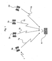
- the device according to the invention is intended to be carried aboard a space system such as a satellite 2a, 2b, 2c, 2d belonging to a constellation 1 of satellites adapted to allow radionavigation and / or radiopositioning of receivers 6 located on Earth or on a terrestrial satellite - in particular terrestrial receivers or on board satellites or aircraft-.
- the invention is particularly intended to equip satellites of the Galileo constellation for the emission of navigation codes in the E5 band.
- a device according to the invention may also, alternatively or in combination, be used in pseudolites (or pseudo-satellites) which are beacons, generally on the ground, generating a navigation signal close to a navigation signal broadcast by a satellite.
- pseudolites or pseudo-satellites
- pseudo-satellites are beacons, generally on the ground, generating a navigation signal close to a navigation signal broadcast by a satellite.
- Each satellite 2a, 2b, 2c, 2d therefore comprises a device according to the invention for generating a modulated navigation signal 7a, 7b, 7c, 7d comprising a plurality of pseudo-random navigation codes intended to be used for positioning.
- receiver 6 downlink.
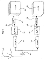
- This generation device comprises a reception antenna 8 associated with a data receiver circuit 9, so that the generation device can receive data or navigation messages-especially from the ground in general for the management of the constellation 1 by the ground control segment may be incorporated wholly or partly in the modulated navigation signal.
- the generation device also comprises a clock circuit 10 supplying a reference frequency f0 to a navigation code generation circuit 11 and to a carrier signal generation circuit 12.
- the navigation code generation circuit 11 optionally receives the data coming from the data receiver 9.
- the navigation codes coming from the circuit 11 are modulated by a modulator circuit 13 on the carrier signal coming from the circuit 12.
- the modulated signal thus obtained is delivered to a transmitting antenna 14 via a transmitter circuit 15 amplification and filtering, so that the transmitting antenna 14 transmits the modulated navigation signal 7 conveying the different pseudo-random navigation codes.
- This navigation signal 7 is received by a receiver 6 whose block diagram is shown in FIG. 3.
- This receiver 6 comprises a reception antenna 18 associated with a radiofrequency reception circuit 19, which conventionally comprises an amplification and filtering chain. , frequency conversion, and analog / digital conversion.
- This radiofrequency reception circuit 19 thus provides a digital modulated signal to signal processing circuits 20, namely, a circuit 20a, 20b, 20c, 20d for each navigation signal 7a, 7b, 7c, 7d from each satellite 2a. , 2b, 2c, 2d so as to allow simultaneous processing of these signals. It should be noted that it is possible to use more than four satellites, and thus more than four processing circuits in a receiver.
- Each signal processing circuit 20 makes it possible to extract raw measurements 21 and, where appropriate, navigation data (or messages) 22 conveyed by one and / or the other of the codes of the modulated navigation signal received.
- the raw measurements 21 consist notably of a pseudo-distance calculation between the corresponding 2a, 2b, 2c, 2d and the receiver 6. It may also be a so-called “pseudo-speed” or "integrated Doppler” calculation. realized on the carrier signal.
- These raw measurements are traditional and well known - especially in the case of the GPS constellation.
- the raw measurements 21 and the possible navigation data 22 are supplied to a navigation calculation circuit 23 which supplies, on the one hand, the raw measurements 21 and the navigation data 22 that it receives, and on the other hand, a result of calculation, in particular a position signal of the receiver 6.
- the receiver 6 also comprises a clock circuit 25 delivering a reference frequency on the one hand to the radiofrequency reception circuit 19, and on the other hand to the different signal processing circuits 20.
- FIG. 4 shows in more detail the block 16 comprising the circuits 9, 10, 11, 12, 13, represented in FIG. 2 by dashed lines, and which makes it possible to implement the method according to the invention.
- This block 16 comprises the clock circuit 10 generating an analog clock signal at the reference frequency fo, which is for example of the order of 10.23 MHz.
- This reference frequency fo is supplied to a circuit 26 generating square signals clocked at the reference frequency f0.
- These square signals at the reference frequency f0 are supplied to four frequency converters 27-1, 27-1 ', 27-2, 27-2' which deliver square signals of frequency fc1, fc1 ', fc2, fc2', respectively to four pseudo-random navigation code generator circuits 28-1, 28-1 ', 28-2, 28-2', respectively generating four independent pseudo-random navigation codes C1, C1 ', C2, C2'. , to be incorporated in the navigation signal 7.
- the square signal generating circuit 26 at the frequency f0 also supplies these square signals to a frequency converter 29 supplying square signals at a frequency fM, which is the modulation frequency, a cyclic counter for generating eight numerical values, from 1 to 8, cyclically to clock the modulator circuit 13 at the modulation frequency fM.
- a frequency converter 29 supplying square signals at a frequency fM, which is the modulation frequency, a cyclic counter for generating eight numerical values, from 1 to 8, cyclically to clock the modulator circuit 13 at the modulation frequency fM.
- a reset circuit 31 makes it possible to initialize and synchronize at start-up the four circuits 28-1, 28-1 ', 28-2, 28-2' generating codes, as well as the counter 30, and therefore the modulator 13.
- the data receiver circuit 9 optionally provides navigation data (messages) to one and / or the other of the code generator circuits 28-1, 28-1 ', 28-2, 28-2', so that this navigation data can be embedded in the pseudo-random code, but at a much lower frequency.
- the four circuits 28-1, 28-1 ', 28-2, 28-2' form the circuit 11 shown in FIG. 2 whose function is to generate the pseudo-random navigation codes.
- the modulator circuit 13 is adapted to carry out the modulation according to the method of the invention, according to an 8-PSK modulation of constant amplitude with a modulation frequency fM defined by the signals delivered by the counter 30.
- the circuit 12 generating the carrier signal is formed of a frequency converter circuit 32 receiving the analog clock signal at the reference frequency f 0 and supplying an analog signal at the frequency of the carrier fp.
- the carrier signal fp is delivered to two parallel carrier branches, one of which provides the carrier signal in phase, and the other carrier circuit 34 comprises a ⁇ / 2 phase shifter providing a carrier signal in quadrature at the frequency fp.
- fM ⁇ 400 MHz, and more particularly fM ⁇ 200 MHz, is chosen for an on-board device. Max denotes the maximum function, fc being the largest value of fci.
- the different chip rates of pseudo-random navigation codes are all greater than 0.5 MHz and preferably greater than 1 MHz.
- the chip rate envisioned is 2.046 MHz for all codes.
- the frequency of the carrier fp must be greater than 500 MHz, and is typically between 1000 MHz and 1700 MHz.
- the band E5a is at a carrier frequency of 1176.45 MHz and the band E5b is at a frequency of 1207.14 MHz.
- the band E1 is at 1589.742 MHz and the band G1 is up to 1610 MHz.
- the modulator circuit 13 comprises a logic circuit 45 which provides at its output 36 a baseband 8-PSK modulation signal at the frequency fM carrying the four navigation codes C1, C2, C1 ', C2'.
- This modulation signal can thus take eight phase states corresponding to the constellation of the 8-PSK modulation, that is to say to the different pads P1, P2, P3, P4, P5, P6, P7, P8 of this constellation as shown in FIG.
- the logic circuit 45 uses four navigation codes, for example according to the following truth table: TABLE 1 C1 (t) -1 -1 -1 -1 -1 -1 -1 -1 1 1 1 1 1 1 1 1 1 C2 (t) -1 -1 -1 -1 1 1 1 1 1 1 1 1 1 1 C1 '(t) -1 -1 1 1 -1 -1 1 1 1 -1 -1 1 1 1 C2 '(t) -1 1 -1 1 -1 1 -1 1 -1 1 -1 1 -1 1 t modulo 8TM [0, TM [ P5 P4 P4 P3 P6 P7 P5 P2 P6 P1 P3 P2 P7 P8 P1 [TM, 2TM [ P5 P8 P4 P3 P6 P7 P5 P6 P2 P1 P3 P2 P7 P8 P4 P1 [2TM, 3TM [ P1 P8 P4 P7 P6 P7 P6 P2 P1 [2TM, 3TM [ P1 P8 P4 P7 P6 P7 P
- TM 1 / fM.
- the eight truth tables can be obtained with a constellation similar to that of FIG. 8 but with studs traversed in the clockwise direction (and not in the opposite direction of the needles). a watch as in FIG. 8), are in fact identical, with rotation, to the eight previously defined truth tables and can thus also be used. Indeed, it suffices to invert C1, C1 'and C2, C2' to move from a constellation traveled in one direction to the constellation having the same pads but traveled in the opposite direction.
- TM 1 / fM.
- the method according to the invention can be likened to an alternative BOC modulation (at two frequencies f1 and f2 around the carrier frequency and separated from this carrier frequency by a subcarrier frequency of fM / 8 value ) but defined from a cosine or sine subcarrier (such as that used for a LOC modulation, from which only discrete points are exploited to ensure that the baseband modulation signal has a constant amplitude ).
- the baseband modulation signal x (t) delivered on the output 36 of the modulation logic circuit 45 is supplied to a branch 37 in phase and to a branch 38 in quadrature.
- the phase branch 37 comprises a filter 39 which extracts the values in phase I of the modulation signal, and a mixer 40 which combines them with the carrier signal at the frequency fp originating from the carrier branch in phase 33.
- the quadrature branch 38 comprises a filter 41 which extracts the quadrature values Q of the modulation signal and a mixer 42 which modulates these values on the carrier signals at the frequency fp delivered by the quadrature carrier branch 34.
- phase (at the output of the branch 37) and in quadrature (at the output of the branch 38) are combined by an in-phase summator circuit 43 delivering a single modulated signal at its output 44 connected to the input of the amplification transmitter circuit and filtering device 15 for transmitting the modulated navigation signal 7.
- FIG. 7 gives an example of timing diagrams for the four codes C1, C2, C1 ', C2' and for the I and Q channels of the modulation signal used at the input of the mixer circuits 40, 42. With this modulation signal, the modulated signal delivered on the output 44 has a constant envelope.
- Figures 5 and 6 show two embodiments of an architecture at the receiver 6 for the operation of the navigation signal modulated by the device according to the invention.
- the radiofrequency reception chain includes the antenna of receiver 18 connected to a low-noise amplifier 46 followed by a frequency conversion circuit 47, which converts the signal received from the frequency fp to an intermediate frequency fi specific to the receiver adapted to then allow an analog / digital conversion in the best possible conditions.
- the signal is then transmitted to a bandpass filter 48 which makes it possible to keep in the modulated navigation signal only the two main lobes corresponding to the frequencies f1 and f2, by eliminating the components outside these lobes.
- the passband of the bandpass filter 48 is greater than or equal to 2fM / 8 + 2fc, and preferably of the order of this value corresponding to the frequency spread of the two lobes of the navigation signal on the frequencies. f1 and f2.
- the filtered signal is supplied to an analog digital converter 49 which outputs a digital signal corresponding to signal processing circuits 50 together forming one of the signal processing circuits 20 described above with reference to FIG. different circuits 50 each allow the processing of different pseudo-random navigation codes C1, C2, C1 ', C2' together or not.
- the number of circuits 50 depends on the use that is made of the receiver and the services available to the user of this receiver. It is thus possible that the receiver has permission to exploit only part of the codes, for example, C1 and C1 '.
- the two frequencies f1 and f2 are processed separately on two distinct branches.
- the output of amplifier 46 supplies a first branch 51 and a second branch 52 in parallel.
- the lobe centered on the frequency f1 of the navigation signal is processed.
- This branch 51 thus comprises a converter circuit 53 of the frequency f1 to the intermediate frequency fi, followed by a bandpass filter 54 which makes it possible to keep only the lobe at the frequency f1, the passband of the filter 54 being between 2fM / 8 and 2fc, an analog digital converter 55 and a plurality of signal processing circuit 56 for extracting the two navigation codes C1, C1 '.
- the branch 42 comprises a frequency converter circuit 57 (from f2 to fi) followed by a bandpass filter 58 of bandwidth between 2 fM / 8 and 2 fc, making it possible to extract the components on the lobe of FIG. frequency f2, a converter digital analog 59 and signal processing circuits 60 to extract the codes C2, C2 '.
- FIG. 9 represents an exemplary modulated navigation signal spectrum as transmitted by the payload (transmitter).
- the center frequency is fp.
- this signal comprises two main side lobes, one at the frequency f1, the other at the frequency f2.
- Fig. 10 shows an example of a modulated navigation signal spectrum obtained after the bandpass filtering of the filter 48 of Fig. 5 in a receiver.
- this signal comprises two main side lobes, one at the frequency f1, the other at the frequency f2.
- FIG. 11 shows an example of a modulated navigation signal spectrum obtained after the bandpass filtering of the filter 54 in a receiver of FIG. 6. Only the lobe centered by the frequency f1 is present. This lobe contains the signals C1 and C1 '.
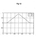
- FIG. 12 is the correlation function of the signal having the spectrum of FIG. 11 correlated with the replica of the codes C1 and C1 ', as generated by the receiver.
- the correlation peak (quasi-triangular shape) indicates the presence of the codes C1 and C1 'in the signal of FIG. 11, and therefore an excellent correlation.
- the navigation codes used are four pseudo-random codes of the type envisaged for the Galileo constellation.
- receiver architectures can be very different, and there are many known technologies in the field.
- the various functions described can also be the subject of various structural achievements well known in themselves.
- the value of fc is of the order of 10 MHz and the value of fM is of the order of 120 MHz. Nevertheless, other values are possible and compatible with a method and a navigation device according to the invention.
Landscapes
- Engineering & Computer Science (AREA)
- Radar, Positioning & Navigation (AREA)
- Remote Sensing (AREA)
- Computer Networks & Wireless Communication (AREA)
- Physics & Mathematics (AREA)
- General Physics & Mathematics (AREA)
- Position Fixing By Use Of Radio Waves (AREA)
- Amplifiers (AREA)
- Traffic Control Systems (AREA)
- Navigation (AREA)
- Investigating Or Analysing Biological Materials (AREA)
- Measurement And Recording Of Electrical Phenomena And Electrical Characteristics Of The Living Body (AREA)
Claims (22)
- Verfahren zum Erzeugen eines modulierten Navigationssignals (7), das zum Positionieren eines Empfängers (6) durch eine Abwärtsverbindung verwendet wird, umfassend eine Mehrzahl von pseudozufälligen Navigationscodes von Chipraten über 0,5 MHz, die auf einer Trägerwelle mit einer Frequenz fp über 500 MHz moduliert sind, dadurch gekennzeichnet, dass auf der Trägerwelle vier pseudozufällige Navigationscodes C1, C2, C1', C2' gemäß einer konstanten 8-PSK Amplitudenmodulation mit einer Modulationsfrequenz fM moduliert werden, so dass:

- Verfahren nach Anspruch 1, dadurch gekennzeichnet, dass fM ≤ 400 MHz gewählt wird.
- Verfahren nach Anspruch 1 zur Erzeugung eines modulierten Navigationssignals (7) an Bord eines Raumsatelliten, dadurch gekennzeichnet, dass fM ≤ 200 MHz gewählt wird.
- Verfahren nach einem der Ansprüche 1 bis 3, dadurch gekennzeichnet, dass eine in der Fresnel-Ebene symmetrische konstante 8-PSK Amplitudenmodulation verwendet wird.
- Verfahren nach einem der Ansprüche 1 bis 3, dadurch gekennzeichnet, dass eine in der Fresnel-Ebene asymmetrische konstante 8-PSK Amplitudenmodulation verwendet wird.
- Verfahren nach einem der Ansprüche 1 bis 5, dadurch gekennzeichnet, dass eine 8-PSK Modulation mit Phasenzuständen gleich k.π/4 verwendet wird, wobei k eine ganze Zahl zwischen 1 und 8 ist.
- Verfahren nach einem der Ansprüche 1 bis 6, dadurch gekennzeichnet, dass die vier Codes gemäß einer Wahrheitstabelle moduliert werden, die aus der folgenden Gruppe von Wahrheitstabellen ausgewählt wird:
TABELLE 1 C1(t) -1 -1 -1 -1 -1 -1 -1 -1 1 1 1 1 1 1 1 1 C2(t) -1 -1 -1 -1 1 1 1 1 -1 -1 -1 -1 1 1 1 1 C1'(t) -1 -1 1 1 -1 -1 1 1 -1 -1 1 1 -1 -1 1 1 1 1 C2'(t) -1 1 -1 1 -1 1 -1 1 -1 1 -1 1 -1 1 -1 1 t modulo 8TM [0, TM[ P5 P4 P4 P3 P6 P7 P5 P2 P6 P1 P3 P2 P7 P8 P8 P1 [TM, 2TM[ P5 P8 P4 P3 P6 P7 P5 P6 P2 P1 P3 P2 P7 P8 P4 P1 [2TM, 3TM[ P1 P8 P4 P7 P6 P7 P5 P6 P2 P1 P3 P2 P3 P8 P4 P5 [3TM, 4TM[ P1 P8 P8 P7 P2 P7 P5 P6 P2 P1 P3 P6 P3 P4 P4 P5 [4TM, 5TM[ P1 P8 P8 P7 P2 P3 P1 P6 P2 P5 P7 P6 P3 P4 P4 P5 [5TM, 6TM[ P1 P4 P8 P7 P2 P3 P1 P2 P6 P5 P7 P6 P3 P4 P8 P5 [6TM, 7TM[ P5 P4 P8 P3 P2 P3 P1 P2 P6 P5 P7 P6 P7 P4 P8 P1 [7TM, 8TM[ P5 P4 P4 P3 P6 P3 P1 P2 P6 P5 P7 P2 P7 P8 P8 P1 TABELLE 2 wobei P1, P2, P3, P4, P5, P6, P7, P8 die unterschiedlichen Plots und die Konstellation 8-PSK sind und TM = 1/fM ist, und gemäß anderen Wahrheitstabellen, die durch Phasenrotation von n.π/4 aus diesen Wahrheitstabellen TABELLE 1 und TABELLE 2 hervorgehen, wobei n ∈{1,2,3,4,5,6,7} und/oder eine Verlaufsrichtungsumkehr der Konstellation ist.C1(t) -1 -1 -1 -1 -1 -1 -1 -1 1 1 1 1 1 1 1 1 C2(t) -1 -1 -1 -1 1 1 1 1 -1 -1 -1 -1 1 1 1 1 C1'(t) -1 -1 1 1 -1 -1 1 1 -1 -1 1 1 -1 -1 1 1 C2'(t) -1 1 -1 1 -1 1 -1 1 -1 1 -1 1 -1 1 -1 1 t modulo 8TM [0, TM[ P1 P8 P4 P7 P6 P7 P5 P6 P2 P1 P3 P2 P3 P8 P4 P5 [TM, 2TM[ P1 P8 P8 P7 P2 P7 P5 P6 P2 P1 P3 P6 P3 P4 P4 P5 [2TM, 3TM[ P1 P8 P8 P7 P2 P3 P1 P6 P2 P5 P7 P6 P3 P4 P4 P5 [ 3TM, 4TM [ P1 P4 P8 P7 P2 P3 P1 P2 P6 P5 P7 P6 P3 P4 P8 P5 [ 4TM, 5TM [ P5 P4 P8 P3 P2 P3 P1 P2 P6 P5 P7 P6 P7 P4 P8 P1 [ 5TM, 6TM [ P5 P4 P4 P3 P6 P3 P1 P2 P6 P5 P7 P2 P7 P8 P8 P1 [ 6TM, 7TM [ P5 P4 P4 P3 P6 P7 P5 P2 P6 P1 P3 P2 P7 P8 P8 P1 [ 7TM, 8TM [ P5 P8 P4 P3 P6 P7 P5 P6 P2 P1 P3 P2 P7 P8 P4 P1 - Verfahren nach einem der Ansprüche 1 bis 7, dadurch gekennzeichnet, dass fp zwischen 1000 MHz und 1700 MHz liegt.
- Verfahren nach einem der Ansprüche 1 bis 8, dadurch gekennzeichnet, dass fc bei etwa 10 MHz liegt.
- Verfahren nach einem der Ansprüche 1 bis 9, dadurch gekennzeichnet, dass fM bei etwa 120 MHz liegt.
- Verfahren nach einem der Ansprüche 1 bis 10, dadurch gekennzeichnet, dass in wenigstens einem Codepaar C1, C1'; C2, C2', das auf derselben Frequenz quadraturmoduliert ist, ein C1'; C2' digitale Daten enthält, die gemäß einer Frequenz moduliert sind, die kleiner als fc/1000 ist.
- Vorrichtung zum Erzeugen eines modulierten Navigationssignals (7) für die Verwendung zum Positionieren eines Empfängers (6) durch eine Abwärtsverbindung, umfassend eine Mehrzahl von pseudozufälligen Navigationscodes mit Chipraten über 0,5 MHz, die auf einer Trägerwelle mit einer Frequenz fp über 500 MHz moduliert sind, wobei diese Vorrichtung Folgendes umfasst:- eine Generatorschaltung (11) für pseudozufällige Navigationscodes,- eine Modulatorschaltung (13) durch Phasenverschiebung, die das modulierte Navigationssignal (7) auf der Trägerwelle liefert,- eine Emitterschaltung (15), die wenigstens eine Leistungsverstärkungsstufe umfasst, zum Emittieren eines Funkfrequenzsignals, das dem modulierten Navigationssignal entspricht,dadurch gekennzeichnet, dass die Modulatorschaltung (13) die Aufgabe hat, auf der Trägerwelle vier pseudozufällige Navigationscodes C1, C2, C1', C2' zu modulieren, deren Frequenzen ein ganzzahliges Vielfaches von einem fc-Wert davon ist, gemäß einer konstanten 8-PSK Amplitudenmodulation mit einer Modulationsfrequenz fM wie:

wobei fc = Max(fci) ist, wobei fci die Chipraten fc1, fc1', fc2, fc2' der Navigationscodes C1, C2, C1', C2' bedeutet, wobei jeder Wert fci so ist, dass fM = Ni.fci ist, wobei Ni eine ganze Zahl gleich oder größer als 8 ist, wobei zwei Navigationscodes C1, C1' auf der Frequenz f1 = fp - fM/8 quadraturmoduliert sind, und zwei weitere Navigationscodes C2, C2' auf der Frequenz f2 = fp + fM/8 quadraturmoduliert sind, wobei das modulierte Navigationssignal eine konstante Hüllkurve hat. - Vorrichtung nach Anspruch 12, dadurch gekennzeichnet, dass die Modulatorschaltung (13) die Aufgabe hat, eine 8-PSK Modulation mit einer Modulationsfrequenz von fM ≤ 400 MHz zu realisieren.
- Vorrichtung nach Anspruch 12, dadurch gekennzeichnet, dass die Modulatorschaltung (13) die Aufgabe hat, eine 8-PSK Modulation mit einer Modulationsfrequenz fM ≤ 200 MHz zu realisieren.
- Vorrichtung nach einem der Ansprüche 12 bis 14,
dadurch gekennzeichnet, dass die Modulatorschaltung (13) die Aufgabe hat, eine in der Fresnel-Ebene konstante symmetrische 8-PSK Amplitudenmodulation zu realisieren. - Vorrichtung nach einem der Ansprüche 12 bis 14, dadurch gekennzeichnet, dass die Modulatorschaltung (13) die Aufgabe hat, eine in der Fresnel-Ebene konstante asymmetrische 8-PSK Amplitudenmodulation zu realisieren.
- Vorrichtung nach einem der Ansprüche 12 bis 16,
dadurch gekennzeichnet, dass die Modulatorschaltung (13) die Aufgabe hat, eine 8-PSK Phasenmodulation von gleich k.π/4 zu realisieren, wobei k eine ganze Zahl zwischen 1 und 8 ist. - Vorrichtung nach einem der Ansprüche 12 bis 17, dadurch gekennzeichnet, dass die Modulatorschaltung (13) die Aufgabe hat, die vier Codes gemäß einer Wahrheitstabelle zu modulieren, die aus der folgenden Gruppe von Wahrheitstabellen ausgewählt wird:
TABELLE 1 C1(t) -1 -1 -1 -1 -1 -1 -1 .1 1 1 1 1 1 1 1 1 C2(t) -1 -1 -1 -1 1 1 1 1 -1 -1 -1 -1 1 1 1 1 C1'(t) -1 -1 1 1 -1 -1 1 1 -1 -1 1 1 -1 -1 1 1 C2'(t) -1 1 -1 1 -1 1 -1 1 -1 1 -1 1 -1 1 -1 1 t modulo 8TM [0, TM[ P5 P4 P4 P3 P6 P7 P5 P2 P6 P1 P3 P2 P7 P8 P8 P1 [TM, 2TM[ P5 P8 P4 P3 P6 P7 P5 P6 P2 P1 P3 P2 P7 P8 P4 P1 [2TM, 3TM[ P1 P8 P4 P7 P6 P7 P5 P6 P2 P1 P3 P2 P3 P8 P4 P5 [3TM, 4TM[ P1 P8 P8 P7 P2 P7 P5 P6 P2 P1 P3 P6 P3 P4 P4 P5 [4TM, 5TM[ P1 P8 P8 P7 P2 P3 P1 P6 P2 P5 P7 P6 P3 P4 P4 P5 [5TM, 6TM[ P1 P4 P8 P7 P2 P3 P1 P2 P6 P5 P7 P6 P3 P4 P8 P5 [6TM, 7TM[ P5 P4 P8 P3 P2 P3 P1 P2 P6 P5 P7 P6 P7 P4 P8 P1 [7TM, 8TM[ P5 P4 P4 P3 P6 P3 P1 P2 P6 P5 P7 P2 P7 P8 P8 P1 TABELLE 2 wobei P1, P2, P3, P4, P5, P6, P7, P8 die unterschiedlichen Plots und die Konstellation 8-PSK sind und TM = 1/fM ist, und gemäß weiteren Wahrheitstabellen, die durch Phasenrotation von n.π/4 aus diesen Wahrheitstabellen TABELLE 1 und TABELLE 2 hervorgehen, wobei n ∈{1,2,3,4,5,6,7} und/oder eine Verlaufsrichtungsumkehr der Konstellation ist.C1(t) -1 -1 -1 -1 -1 -1 -1 -1 1 1 1 1 1 1 1 1 C2(t) -1 -1 -1 -1 1 1 1 1 -1 -1 -1 -1 1 1 1 1 C1'(t) -1 -1 1 1 -1 -1 1 1 -1 -1 1 1 -1 -1 1 1 C2'(t) -1 1 -1 1 -1 1 -1 1 -1 1 -1 1 -1 1 -1 1 t modulo 8TM [0, TM[ P1 P8 P4 P7 P6 P7 P5 P6 P2 P1 P3 P2 P3 P8 P4 P5 [TM, 2TM[ P1 P8 P8 P7 P2 P7 P5 P6 P2 P1 P3 P6 P3 P4 P4 P5 [2TM, 3TM[ P1 P8 P8 P7 P2 P3 P1 P6 P2 P5 P7 P6 P3 P4 P4 P5 [3TM, 4TM[ P1 P4 P8 P7 P2 P3 P1 P2 P6 P5 P7 P6 P3 P4 P8 P5 [4TM, 5TM[ P5 P4 P8 P3 P2 P3 P1 P2 P6 P5 P7 P6 P7 P4 P8 P1 [5TM, 6TM[ P5 P4 P4 P3 P6 P3 P1 P2 P6 P5 P7 P2 P7 P8 P8 P1 [6TM, 7TM[ P5 P4 P4 P3 P6 P7 P5 P2 P6 P1 P3 P2 P7 P8 P8 P1 [7TM, 8TM[ P5 P8 P4 P3 P6 P7 P5 P6 P2 P1 P3 P2 P7 P8 P4 P1 - Vorrichtung nach einem der Ansprüche 12 bis 17, dadurch gekennzeichnet, dass fp zwischen 1000 MHz und 1700 MHz liegt.
- Vorrichtung nach einem der Ansprüche 12 bis 19, dadurch gekennzeichnet, dass fc bei etwa 10 MHz liegt.
- Vorrichtung nach einem der Ansprüche 12 bis 20, dadurch gekennzeichnet, dass fM bei etwa 120 MHz liegt.
- Vorrichtung nach einem der Ansprüche 12 bis 21,
dadurch gekennzeichnet, dass sie so gestaltet ist, dass in wenigstens einem Codepaar, das auf derselben Frequenz quadraturmoduliert ist, ein C1', C2' modulierte digitale Daten gemäß einer Frequenz von weniger als fc/1000 beinhaltet.
Applications Claiming Priority (3)
| Application Number | Priority Date | Filing Date | Title |
|---|---|---|---|
| FR0215848 | 2002-12-13 | ||
| FR0215848A FR2848748B1 (fr) | 2002-12-13 | 2002-12-13 | Procede et dispositif de generation d'un signal de navigation a enveloppe constante a quatre codes independants |
| PCT/FR2003/003695 WO2004055541A1 (fr) | 2002-12-13 | 2003-12-12 | Procede et dispositif de generation d'un signal de navigation a enveloppe constante a quatre codes independants |
Publications (2)
| Publication Number | Publication Date |
|---|---|
| EP1570287A1 EP1570287A1 (de) | 2005-09-07 |
| EP1570287B1 true EP1570287B1 (de) | 2006-05-03 |
Family
ID=32338784
Family Applications (1)
| Application Number | Title | Priority Date | Filing Date |
|---|---|---|---|
| EP03813176A Expired - Lifetime EP1570287B1 (de) | 2002-12-13 | 2003-12-12 | Verfahren und vorrichtung zur erzeugung eines konstanten hüllkurvennavigationssignals mit vier unabhängigen codes |
Country Status (7)
| Country | Link |
|---|---|
| US (1) | US7561103B2 (de) |
| EP (1) | EP1570287B1 (de) |
| AT (1) | ATE325350T1 (de) |
| DE (1) | DE60305066T2 (de) |
| ES (1) | ES2264040T3 (de) |
| FR (1) | FR2848748B1 (de) |
| WO (1) | WO2004055541A1 (de) |
Families Citing this family (7)
| Publication number | Priority date | Publication date | Assignee | Title |
|---|---|---|---|---|
| DE10219216B4 (de) | 2002-04-29 | 2005-04-07 | Eads Astrium Gmbh | Verfahren und Endgerät zur Verarbeitung eines Navigationssignals in einem Satelliten-Navigationssystem |
| GB0320352D0 (en) | 2003-09-01 | 2003-10-01 | Secr Defence | Digital modulation waveforms for use in ranging systems |
| US7885363B2 (en) | 2007-10-18 | 2011-02-08 | Mediatek Inc. | Correlation device and method for different modulated signals |
| US8111735B2 (en) * | 2008-01-28 | 2012-02-07 | Mediatek Inc. | GNSS data/pilot correlator and code generator thereof |
| CN102694569B (zh) | 2012-06-07 | 2014-05-14 | 清华大学 | 导航信号的恒包络复用方法、生成装置以及接收方法 |
| CN103023598B (zh) | 2012-11-23 | 2016-03-30 | 清华大学 | 双频四分量扩频信号的恒包络复用方法、装置及接收方法 |
| CN104702311B (zh) | 2013-12-06 | 2017-08-11 | 清华大学 | 扩频信号的生成方法、生成装置、接收方法和接收装置 |
Family Cites Families (11)
| Publication number | Priority date | Publication date | Assignee | Title |
|---|---|---|---|---|
| US4095226A (en) * | 1970-05-01 | 1978-06-13 | Harris Corporation | System for communication |
| US4308617A (en) * | 1977-11-07 | 1981-12-29 | The Bendix Corporation | Noiselike amplitude and phase modulation coding for spread spectrum transmissions |
| US5022049A (en) * | 1989-11-21 | 1991-06-04 | Unisys Corp. | Multiple access code acquisition system |
| JP2900671B2 (ja) * | 1991-11-29 | 1999-06-02 | ソニー株式会社 | Gps受信機 |
| US5483511A (en) * | 1993-02-17 | 1996-01-09 | Vixel Corporation | Multiple beam optical memory system with solid-state lasers |
| US5995233A (en) * | 1994-06-21 | 1999-11-30 | Kabushiki Kaisha Topcon | Surveying system |
| US5637826A (en) * | 1996-02-07 | 1997-06-10 | The United States Of America As Represented By The Secretary Of The Navy | Method and apparatus for optimal guidance |
| FR2759515B1 (fr) * | 1997-02-13 | 1999-03-19 | Alsthom Cge Alcatel | Emetteur de signaux a acces multiples par repartition de code, station de base d'un reseau cdma et terminal comprenant un tel emetteur |
| US6075810A (en) * | 1998-01-28 | 2000-06-13 | The Aerospace Corporation | NRZ and biphase-L formatted hexaphase modulated GPS transmission method |
| US6335951B1 (en) * | 1998-12-04 | 2002-01-01 | Itt Manufacturing Enterprises, Inc. | Programmable waveform generator for a global positioning system |
| WO2003026189A1 (en) * | 2001-09-20 | 2003-03-27 | Itt Manufacturing Enterprises, Inc. | Methods and apparatus for satellite link throughput adaptation |
-
2002
- 2002-12-13 FR FR0215848A patent/FR2848748B1/fr not_active Expired - Fee Related
-
2003
- 2003-12-12 WO PCT/FR2003/003695 patent/WO2004055541A1/fr not_active Ceased
- 2003-12-12 DE DE60305066T patent/DE60305066T2/de not_active Expired - Lifetime
- 2003-12-12 ES ES03813176T patent/ES2264040T3/es not_active Expired - Lifetime
- 2003-12-12 EP EP03813176A patent/EP1570287B1/de not_active Expired - Lifetime
- 2003-12-12 US US10/537,800 patent/US7561103B2/en not_active Expired - Lifetime
- 2003-12-12 AT AT03813176T patent/ATE325350T1/de active
Also Published As
| Publication number | Publication date |
|---|---|
| FR2848748B1 (fr) | 2005-02-18 |
| US7561103B2 (en) | 2009-07-14 |
| WO2004055541A1 (fr) | 2004-07-01 |
| DE60305066T2 (de) | 2007-04-19 |
| ES2264040T3 (es) | 2006-12-16 |
| ATE325350T1 (de) | 2006-06-15 |
| US20060038716A1 (en) | 2006-02-23 |
| EP1570287A1 (de) | 2005-09-07 |
| FR2848748A1 (fr) | 2004-06-18 |
| DE60305066D1 (de) | 2006-06-08 |
Similar Documents
| Publication | Publication Date | Title |
|---|---|---|
| US8233518B2 (en) | Signals, system, method and apparatus | |
| EP1664827B1 (de) | Modulationssignale für ein satelliten-navigationssystem | |
| CA2187122C (fr) | Recepteur large bande a mesure de distance par signaux de code pseudo-aleatoire | |
| EP3454090B1 (de) | Verfahren und vorrichtung zur signalerfassung eines verallgemeinerten boc-modulierten signals | |
| EP2074704B1 (de) | Verfahren zum empfang und empfänger für ein durch eine cboc- oder tmboc-spreizsignalform moduliertes funknavigationssignal | |
| EP1514131B1 (de) | Satellitenpositionierungssystem-empfänger mit zwei signalträgern | |
| CA2674544C (fr) | Procede et dispositif de reception d'un signal de radionavigation a modulation boc | |
| WO2005006012A1 (fr) | Procede et dispositif de demodulation de signaux de radionavigation par satellite. | |
| FR2783929A1 (fr) | Procede et dispositif de traitement en reception d'un signal l2 de satellite gps | |
| EP1949124B1 (de) | Entfernung des binären Unterträgers und Heruntertakten des Empfangssignals | |
| CN104798307A (zh) | 使用具有交错式伪随机码码相位跟踪的gnss系统及方法 | |
| EP1570287A1 (de) | Verfahren und vorrichtung zur erzeugung eines konstanten hüllkurvennavigationssignals mit vier unabhängigen codes | |
| WO2007147807A1 (fr) | Procede de reception et recepteur pour un signal de radionavigation module par une forme d'onde d'etalement cboc | |
| FR3024241B1 (fr) | Dispositif de geolocalisation | |
| EP1477004B1 (de) | Frequenzmodulator für digitale übertragungen | |
| Ala-Poikela | BEIDOU B1C IMPLEMENTATION ON A SOFTWARE-DEFINED GNSS RECEIVER | |
| FR2902949A1 (fr) | Procede de reception et recepteur pour un signal de radionavigation module par une forme d'onde d'etalement cboc | |
| EP1229665B1 (de) | Verfahren und Vorrichtung zur Verarbeitung eines empfangenen digitalen Spreizspektrumsignals | |
| EP1255123B1 (de) | Funksignalempfänger mit Mittel zur Vergrösserung der Dynamik des Empfangs der Signale | |
| FR2905010A1 (fr) | Procede de reception et recepteur pour un signal de radionavigation module par une forme d'onde d'etalement cboc |
Legal Events
| Date | Code | Title | Description |
|---|---|---|---|
| PUAI | Public reference made under article 153(3) epc to a published international application that has entered the european phase |
Free format text: ORIGINAL CODE: 0009012 |
|
| 17P | Request for examination filed |
Effective date: 20050513 |
|
| AK | Designated contracting states |
Kind code of ref document: A1 Designated state(s): AT BE BG CH CY CZ DE DK EE ES FI FR GB GR HU IE IT LI LU MC NL PT RO SE SI SK TR |
|
| GRAP | Despatch of communication of intention to grant a patent |
Free format text: ORIGINAL CODE: EPIDOSNIGR1 |
|
| GRAS | Grant fee paid |
Free format text: ORIGINAL CODE: EPIDOSNIGR3 |
|
| GRAA | (expected) grant |
Free format text: ORIGINAL CODE: 0009210 |
|
| AK | Designated contracting states |
Kind code of ref document: B1 Designated state(s): AT BE BG CH CY CZ DE DK EE ES FI FR GB GR HU IE IT LI LU MC NL PT RO SE SI SK TR |
|
| PG25 | Lapsed in a contracting state [announced via postgrant information from national office to epo] |
Ref country code: SK Free format text: LAPSE BECAUSE OF FAILURE TO SUBMIT A TRANSLATION OF THE DESCRIPTION OR TO PAY THE FEE WITHIN THE PRESCRIBED TIME-LIMIT Effective date: 20060503 Ref country code: RO Free format text: LAPSE BECAUSE OF FAILURE TO SUBMIT A TRANSLATION OF THE DESCRIPTION OR TO PAY THE FEE WITHIN THE PRESCRIBED TIME-LIMIT Effective date: 20060503 Ref country code: NL Free format text: LAPSE BECAUSE OF FAILURE TO SUBMIT A TRANSLATION OF THE DESCRIPTION OR TO PAY THE FEE WITHIN THE PRESCRIBED TIME-LIMIT Effective date: 20060503 Ref country code: IE Free format text: LAPSE BECAUSE OF FAILURE TO SUBMIT A TRANSLATION OF THE DESCRIPTION OR TO PAY THE FEE WITHIN THE PRESCRIBED TIME-LIMIT Effective date: 20060503 Ref country code: FI Free format text: LAPSE BECAUSE OF FAILURE TO SUBMIT A TRANSLATION OF THE DESCRIPTION OR TO PAY THE FEE WITHIN THE PRESCRIBED TIME-LIMIT Effective date: 20060503 Ref country code: SI Free format text: LAPSE BECAUSE OF FAILURE TO SUBMIT A TRANSLATION OF THE DESCRIPTION OR TO PAY THE FEE WITHIN THE PRESCRIBED TIME-LIMIT Effective date: 20060503 Ref country code: CZ Free format text: LAPSE BECAUSE OF FAILURE TO SUBMIT A TRANSLATION OF THE DESCRIPTION OR TO PAY THE FEE WITHIN THE PRESCRIBED TIME-LIMIT Effective date: 20060503 |
|
| REG | Reference to a national code |
Ref country code: GB Ref legal event code: FG4D Free format text: NOT ENGLISH |
|
| REG | Reference to a national code |
Ref country code: CH Ref legal event code: EP |
|
| REF | Corresponds to: |
Ref document number: 60305066 Country of ref document: DE Date of ref document: 20060608 Kind code of ref document: P |
|
| REG | Reference to a national code |
Ref country code: IE Ref legal event code: FG4D Free format text: LANGUAGE OF EP DOCUMENT: FRENCH |
|
| PG25 | Lapsed in a contracting state [announced via postgrant information from national office to epo] |
Ref country code: DK Free format text: LAPSE BECAUSE OF FAILURE TO SUBMIT A TRANSLATION OF THE DESCRIPTION OR TO PAY THE FEE WITHIN THE PRESCRIBED TIME-LIMIT Effective date: 20060803 |
|
| REG | Reference to a national code |
Ref country code: CH Ref legal event code: NV Representative=s name: BOVARD AG PATENTANWAELTE |
|
| REG | Reference to a national code |
Ref country code: SE Ref legal event code: TRGR |
|
| GBT | Gb: translation of ep patent filed (gb section 77(6)(a)/1977) |
Effective date: 20060816 |
|
| PG25 | Lapsed in a contracting state [announced via postgrant information from national office to epo] |
Ref country code: PT Free format text: LAPSE BECAUSE OF FAILURE TO SUBMIT A TRANSLATION OF THE DESCRIPTION OR TO PAY THE FEE WITHIN THE PRESCRIBED TIME-LIMIT Effective date: 20061003 |
|
| NLV1 | Nl: lapsed or annulled due to failure to fulfill the requirements of art. 29p and 29m of the patents act | ||
| REG | Reference to a national code |
Ref country code: ES Ref legal event code: FG2A Ref document number: 2264040 Country of ref document: ES Kind code of ref document: T3 |
|
| REG | Reference to a national code |
Ref country code: IE Ref legal event code: FD4D |
|
| PG25 | Lapsed in a contracting state [announced via postgrant information from national office to epo] |
Ref country code: MC Free format text: LAPSE BECAUSE OF NON-PAYMENT OF DUE FEES Effective date: 20061231 |
|
| PLBE | No opposition filed within time limit |
Free format text: ORIGINAL CODE: 0009261 |
|
| STAA | Information on the status of an ep patent application or granted ep patent |
Free format text: STATUS: NO OPPOSITION FILED WITHIN TIME LIMIT |
|
| 26N | No opposition filed |
Effective date: 20070206 |
|
| PG25 | Lapsed in a contracting state [announced via postgrant information from national office to epo] |
Ref country code: GR Free format text: LAPSE BECAUSE OF FAILURE TO SUBMIT A TRANSLATION OF THE DESCRIPTION OR TO PAY THE FEE WITHIN THE PRESCRIBED TIME-LIMIT Effective date: 20060804 |
|
| PG25 | Lapsed in a contracting state [announced via postgrant information from national office to epo] |
Ref country code: BG Free format text: LAPSE BECAUSE OF FAILURE TO SUBMIT A TRANSLATION OF THE DESCRIPTION OR TO PAY THE FEE WITHIN THE PRESCRIBED TIME-LIMIT Effective date: 20060803 Ref country code: EE Free format text: LAPSE BECAUSE OF FAILURE TO SUBMIT A TRANSLATION OF THE DESCRIPTION OR TO PAY THE FEE WITHIN THE PRESCRIBED TIME-LIMIT Effective date: 20060503 |
|
| PG25 | Lapsed in a contracting state [announced via postgrant information from national office to epo] |
Ref country code: TR Free format text: LAPSE BECAUSE OF FAILURE TO SUBMIT A TRANSLATION OF THE DESCRIPTION OR TO PAY THE FEE WITHIN THE PRESCRIBED TIME-LIMIT Effective date: 20060503 Ref country code: LU Free format text: LAPSE BECAUSE OF NON-PAYMENT OF DUE FEES Effective date: 20061212 Ref country code: HU Free format text: LAPSE BECAUSE OF FAILURE TO SUBMIT A TRANSLATION OF THE DESCRIPTION OR TO PAY THE FEE WITHIN THE PRESCRIBED TIME-LIMIT Effective date: 20061104 |
|
| PG25 | Lapsed in a contracting state [announced via postgrant information from national office to epo] |
Ref country code: CY Free format text: LAPSE BECAUSE OF FAILURE TO SUBMIT A TRANSLATION OF THE DESCRIPTION OR TO PAY THE FEE WITHIN THE PRESCRIBED TIME-LIMIT Effective date: 20060503 |
|
| REG | Reference to a national code |
Ref country code: CH Ref legal event code: PFA Owner name: CENTRE NATIONAL D'ETUDES SPATIALES ( C.N.E.S.) Free format text: CENTRE NATIONAL D'ETUDES SPATIALES ( C.N.E.S.)#2, PLACE MAURICE QUENTIN#75039 PARIS CEDEX 01 (FR) -TRANSFER TO- CENTRE NATIONAL D'ETUDES SPATIALES ( C.N.E.S.)#2, PLACE MAURICE QUENTIN#75039 PARIS CEDEX 01 (FR) |
|
| REG | Reference to a national code |
Ref country code: FR Ref legal event code: PLFP Year of fee payment: 13 |
|
| REG | Reference to a national code |
Ref country code: FR Ref legal event code: PLFP Year of fee payment: 14 |
|
| REG | Reference to a national code |
Ref country code: FR Ref legal event code: PLFP Year of fee payment: 15 |
|
| PGFP | Annual fee paid to national office [announced via postgrant information from national office to epo] |
Ref country code: SE Payment date: 20221216 Year of fee payment: 20 Ref country code: GB Payment date: 20221228 Year of fee payment: 20 Ref country code: FR Payment date: 20221130 Year of fee payment: 20 Ref country code: DE Payment date: 20221220 Year of fee payment: 20 Ref country code: AT Payment date: 20221220 Year of fee payment: 20 |
|
| PGFP | Annual fee paid to national office [announced via postgrant information from national office to epo] |
Ref country code: BE Payment date: 20221213 Year of fee payment: 20 |
|
| PGFP | Annual fee paid to national office [announced via postgrant information from national office to epo] |
Ref country code: ES Payment date: 20230105 Year of fee payment: 20 Ref country code: CH Payment date: 20221201 Year of fee payment: 20 |
|
| PGFP | Annual fee paid to national office [announced via postgrant information from national office to epo] |
Ref country code: IT Payment date: 20221209 Year of fee payment: 20 |
|
| REG | Reference to a national code |
Ref country code: DE Ref legal event code: R071 Ref document number: 60305066 Country of ref document: DE |
|
| REG | Reference to a national code |
Ref country code: CH Ref legal event code: PL |
|
| REG | Reference to a national code |
Ref country code: ES Ref legal event code: FD2A Effective date: 20231227 |
|
| REG | Reference to a national code |
Ref country code: GB Ref legal event code: PE20 Expiry date: 20231211 |
|
| REG | Reference to a national code |
Ref country code: BE Ref legal event code: MK Effective date: 20231212 |
|
| PG25 | Lapsed in a contracting state [announced via postgrant information from national office to epo] |
Ref country code: GB Free format text: LAPSE BECAUSE OF EXPIRATION OF PROTECTION Effective date: 20231211 |
|
| PG25 | Lapsed in a contracting state [announced via postgrant information from national office to epo] |
Ref country code: ES Free format text: LAPSE BECAUSE OF EXPIRATION OF PROTECTION Effective date: 20231213 |
|
| REG | Reference to a national code |
Ref country code: SE Ref legal event code: EUG |
|
| PG25 | Lapsed in a contracting state [announced via postgrant information from national office to epo] |
Ref country code: GB Free format text: LAPSE BECAUSE OF EXPIRATION OF PROTECTION Effective date: 20231211 Ref country code: ES Free format text: LAPSE BECAUSE OF EXPIRATION OF PROTECTION Effective date: 20231213 |
|
| REG | Reference to a national code |
Ref country code: AT Ref legal event code: MK07 Ref document number: 325350 Country of ref document: AT Kind code of ref document: T Effective date: 20231212 |