EP1570282B1 - Verfahren und gerät zur messung der magnetischen induktion - Google Patents
Verfahren und gerät zur messung der magnetischen induktion Download PDFInfo
- Publication number
- EP1570282B1 EP1570282B1 EP03779582A EP03779582A EP1570282B1 EP 1570282 B1 EP1570282 B1 EP 1570282B1 EP 03779582 A EP03779582 A EP 03779582A EP 03779582 A EP03779582 A EP 03779582A EP 1570282 B1 EP1570282 B1 EP 1570282B1
- Authority
- EP
- European Patent Office
- Prior art keywords
- magnetic field
- magnetic
- measurement
- zeeman
- magnetic fields
- Prior art date
- Legal status (The legal status is an assumption and is not a legal conclusion. Google has not performed a legal analysis and makes no representation as to the accuracy of the status listed.)
- Expired - Lifetime
Links
Images


Classifications
-
- G—PHYSICS
- G01—MEASURING; TESTING
- G01R—MEASURING ELECTRIC VARIABLES; MEASURING MAGNETIC VARIABLES
- G01R33/00—Arrangements or instruments for measuring magnetic variables
- G01R33/20—Arrangements or instruments for measuring magnetic variables involving magnetic resonance
- G01R33/24—Arrangements or instruments for measuring magnetic variables involving magnetic resonance for measuring direction or magnitude of magnetic fields or magnetic flux
- G01R33/26—Arrangements or instruments for measuring magnetic variables involving magnetic resonance for measuring direction or magnitude of magnetic fields or magnetic flux using optical pumping
Definitions
- the present invention relates to an all-optical method and device for measurement of magnetic induction of small magnetic fields and small changes in magnetic fields based on Coherent Resonances (CR).
- small magnetic fields refers to magnetic fields whose induction is within the interval from ⁇ 100 pT to ⁇ 1 mT
- big magnetic fields - to magnetic fields whose induction is higher than ⁇ 1 mT
- a "small change of the magnetic field” refers to a change in the magnetic induction within the interval from ⁇ 100 pT, to ⁇ 1 mT.
- the invention refers to a method and device for measurement of magnetic induction by using CR at a single hyperfine transition in atoms of alkali metals, where the atomic system is coherently excited by means of a laser source with a modulation of the optic frequency with a frequency lower than 1 GHz and where the modulation frequency at which the CR are registered is used as a measure of the induction of the existing magnetic field.
- CPT Coherent Population Trapping
- Two coherent electromagnetic fields excite two transitions of alkali atoms starting from two basic-state hyperfine levels with different energies to a common excited-state level.
- the frequency of one of the transitions is denoted by ⁇ 1 , and of the other - ⁇ 2 , where for example ⁇ 1 > ⁇ 2 .
- Two coherent electromagnetic fields with frequencies ⁇ L1 and ⁇ L2 irradiate the absorbing atomic medium.
- the frequency of one of the electromagnetic fields is ⁇ L1 ⁇ ⁇ 1 , while the frequency of the other field ⁇ L2 is adjusted in a small interval around ⁇ 2 .
- the fluorescence signal from the excited state relaxation or the transmitted through the absorbing medium laser power is registered in dependence on the detuning of ⁇ L2 around ⁇ 2 .
- a narrow dip or peak is registered due to CPT.
- the atomic hyperfine energy levels are split due to Zeeman effect, where the number of the sublevels is determined by the total angular momentum of the respective hyperfine level F and is equal to 2 F + 1.
- the bi-frequency excitation with ⁇ L1 and ⁇ L2 leads to CPT observation at the split Zeeman sublevels of the two basic-state hyperfine levels.
- ⁇ L2 the frequency of one of the electromagnetic fields
- ⁇ L2 around the two-photon Raman resonance condition frequency
- the number of these resonances depends on the total angular momenta of the levels involved in the process.
- the Zeeman splitting of the hyperfine levels depends on the magnetic field strength, where the energy of the magnetic sublevels is given by the Breit-Rabi formula: E
- the frequency difference between the registered CPT resonances in presence of magnetic field is proportional to the magnetic induction B .
- a major advantage of this method of magnetic induction measurement is that it is an all-optical detection. This makes possible the measurement of the induction of magnetic fields at a distance from the registration equipment (by means of optical fibers), thus strongly reducing the influence of the magnetic and electromagnetic fields induced by the measuring apparatus on the measured magnetic field. Besides, the optical method allows the realization of measurements with spatial resolution much higher than that of other existing methods of absolute measurement.
- diode lasers As a most compact and easy-to-use laser source, most frequently the semiconductor lasers (diode lasers) are used. These lasers are suitable for excitation of different transitions in Rb and Cs. Their small size makes them attractive for the solution of practical problems.
- EOM electro-optical modulator
- rf radio-frequency
- the frequency separation between the basic-state hyperfine levels is larger than 1 GHz, and in the case of Cs it reaches 9.2 GHz.
- significant rf power is required - of the order of 1 Watt.
- the application of such high power to the EOM leads to uncontrollable heating of the crystal and thus - to uncontrollable change in the modulation index.
- the change in the modulation index means a change in the intensities of the CPT-preparing electromagnetic fields produced, and thus - to increased noise in the signal and to uncontrolled light shift of the transition. This brings significant errors in the determination of the value of the magnetic field induction due to the shift of the centers of the CPT resonances.
- a GHzz generator is required, as well as a mixer, on which the beat signal between the two lasers is fed after appropriate amplification, for measurement of the frequency difference of the two lasers.
- step (2) the following step is performed:
- the device can also include a system for shielding or compensation of stray magnetic fields, as well as for application of calibrated magnetic field in each direction of the three mutually perpendicular axes for determination of the direction of the measured magnetic field.
- the system for adjustable frequency modulation is preferably a system for direct diode laser current modulation.
- the light of a diode laser with oscillation frequency ⁇ 0 is modulated preferably by direct diode laser injection current modulation, whose modulation frequency ⁇ M is up to several MHz.
- ⁇ M modulation frequency
- the modulation frequency of the diode laser injection current is continuously adjusted in a broad spectral interval.
- the sample of alkali atoms is put under the influence of the measured magnetic field. It removes the Zeeman degeneracy of the atomic levels. A certain transition is chosen - of the I, II or III type.
- a I type transition is chosen.
- a certain type of polarization is selected, preferably linear.
- Figure 1 shows a scheme of the possible Zeeman transitions for one hyperfine transition of the I type at the configuration shown in the inset, which illustrates the laser beam propagation direction (k) along the z axis, and the direction of the electric vector (E) of the linearly polarized light along the y or x axis.
- the incident on the atomic sample laser light can be considered as consisting of two ⁇ + and ⁇ - circularly polarized components.
- Two electromagnetic fields with frequencies ⁇ L1 and ⁇ L2 and polarization ⁇ + and ⁇ - respectively are also shown.
- Continuous adjustment of the modulation frequency ⁇ M is performed, starting from the smallest possible values. Thus, continuous change in the frequency difference between the sidebands in the laser spectrum is accomplished.
- a resonance is registered in the fluorescence or the transmitted power.
- the last registered resonance is due to excitation with two adjacent-order sidebands in the laser spectrum.
- a set of non-equidistant resonances is obtained, whose number is determined by the number of sidebands produced in the laser spectrum with enough power to produce observable CPT effect.
- this finite number of sidebands will be called “number of sidebands in the laser spectrum” and will be denoted by N.
- a possible way to determine the "last" resonance in the set is to track the frequencies ⁇ M n , at which the resonances appear.
- the respective modulation frequency will be denoted by ⁇ M max .
- the procedure when working with a transition of type II is analogical.
- the inset in Figure 2 shows the propagation direction of the laser field, its polarization and the direction of the magnetic field. Two electromagnetic fields with frequencies ⁇ L1 and ⁇ L2 and polarizations ⁇ + and ⁇ - respectively are also shown.
- transition of type III i s chosen.
- the calculation procedure is similar and is illustrated in Figure 3 .
- the CR obtained for this kind of transitions are narrower.
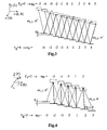
- the magnetic field has non-zero projections on all three axes.
- This case is illustrated in Figure 4 for the case of transitions of type I.
- Zeeman transitions of ⁇ + , ⁇ - and ⁇ type are created.
- CR are registered when coupling of ⁇ + - ⁇ - transitions with a common excited-state Zeeman sublevel, and also when coupling of ⁇ + - ⁇ and ⁇ - - ⁇ transitions with a common excited-state Zeeman sublevel.
- the last resonance though, is again obtained in ⁇ + - ⁇ - coupling.
- the adjacent resonance is registered at a modulation frequency two times smaller than that for the last one. Therefore, the above described procedure for measurement of the magnetic field value is also applicable in the general case of arbitrary orientation of the field.
- the first ones are not resolved.
- a method for measurement of small changes in the magnetic field induction is also proposed.
- the alkali atoms sample is put into a system for magnetic field compensation, which is preferably three pairs of Helmholtz coils in three mutually perpendicular directions.
- the existing big external magnetic field is compensated by means of the current through the coils.
- a small change in this magnetic field which leads to residual non-compensated induction lines, is determined.
- This determination is accomplished by application of a calibrated constant magnetic field with induction B cal along a certain axis, for example x.
- a new field B + or B - is created (higher or smaller in absolute magnitude than B cal , respectively), depending on the quadrant in which the unknown magnetic field B unknown lies.
- Figure 5 presents the case for the x-y plane, where the resultant field is B + .
- This procedure of applying calibrated magnetic field in the two directions of two of the axes x, y and z makes possible to determine the direction of the vector of the unknown magnetic field, knowing its amplitude.
- the angle between the magnetic induction vector and one of the other two axes z and x can be determined as well.
- a laser 1 is used, which is preferably a diode laser, with oscillation frequency ⁇ 0 .
- a modulation system 3 is used.
- the modulation system 3 is a system for direct injection current modulation of the diode laser 1, with a possibility for continuous adjustment of the modulation frequency ⁇ M up to frequencies in the MHz range.
- the emission 2 of the laser is fed to a sample of alkali atoms 4, which is preferably a sealed cell with alkali atoms vapour, for example Cs or Rb, and can be evacuated or with buffer gas added.
- the fluorescence of the atoms 5a, or the transmitted through them laser power 5b is registered.
- a fluorescence registration system 6a is used, and in the second one - a transmission registration system 6b.
- the signal from the registration system 6a or 6b is fed to a processor 7 for data processing and visualization.
- the device can also comprise a system for shielding or compensation of external magnetic fields 8.
- the system 8 can be a magnetic shield made of high-permittivity metal alloy (for example, ⁇ -metal), or a system of three perpendicular pairs of Helmholtz coils along the x, y and z axes, where external magnetic field compensation in the three directions is accomplished through independent control of the current through each pair of the coils.
- the system for application of calibrated magnetic field 9 should be separate.
- the use of a system of three pairs of Helmholtz coils has two advantages. The first one is that it can be used as a system for application of calibrated magnetic field 9 in the three directions, and the other is that it can be also used as a system for compensation of big magnetic field, thus making possible to measure small changes in this field.
Landscapes
- Physics & Mathematics (AREA)
- Condensed Matter Physics & Semiconductors (AREA)
- General Physics & Mathematics (AREA)
- Investigating Or Analysing Materials By Optical Means (AREA)
- Measuring Magnetic Variables (AREA)
Claims (16)
- Methode zur Messung des Vektors der magnetischen Induktion im Bereich kleiner Magnetfelder auf der Grundlage der kohärenten Resonanzen der Zeeman-Subniveaus eines einzelnen Hyperfeinüberganges von Alkali-Atomen, die folgende Schritte umfassen:(a) Schaffung einer frequenzmodulierten Laserstrahlung mit einer Trägerfrequenz ω0 und einer Modulationsfrequenz ΩM derart, dass sich das Laserspektrum aus einer Trägerfrequenz ω0 und den Seitenbändern mit den Frequenzen ω0 ± nΩM zusammensetzt, wobei n eine ganze Zahl darstellt;(b) Aufhebung der Entartung der Zeemaxi-Subniveaus durch die Einwirkung eines äußeren Magnetfeldes (Zeeman-Feld), erreicht durch die Einbringung einer Alkali-Atom-Probe in ein zu messendes Magnetfeld;(c) Messung bzw. Registrierung der Fluoreszenzstrahlung oder der transmittierten Strahlung der Alkali-Atom-Probe,
die derart charakterisiert ist, dass:(d) die (atomare) Population von zwei Zeeman-Subniveaus eines einzelnen Hyperfeinstrukturgrundzustandes mit einem Laserfeld bestimmter Polarisation so angeregt wird, dass ein Übergang/Transfer der Population in einen gemeinsamen, angeregten Zustand stattfindet;(e) die Modulationsfrequenz im Bereich von bis zu MHz liegt und überdies kontinuierlich von einem Minimalwert bis zu dem Bereich der Registrierung, der aus einem kompletten, vom angegebenen Modulationsindex abhängigen, Satz von Resonanzen besteht, welche sich ihrerseits in der Änderung der Intensität der Fluoreszenzstrahlung oder der Änderung der transmittierten Strahlung äußern;(f) die Ermittlung des Proportionalitätsfaktors zwischen der Modulationsfrequenz, bei der die jeweilige Resonanz registriert wird und der Aufspaltung zwischen zwei benachbarten Zeeman Subniveaus und(g) die Berechnung der Größe der magnetischen Induktion nach der Formel von Breit-Rabi gemäß dem erhaltenen Proportionalitätsfaktor und der Modulationsfrequenz, bei der die entsprechende Resonanz nachgewiesen wird. - Methode zur Messung des Vektors der magnetischen Induktion von kleinen Magnetfeldern gemäß Anspruch 1, der die Schritte (a), (b), (c), (d) und (g) umfasst, die dadurch charakterisiert sind, dass die Modulationsfrequenz im Frequenzbereich bis zu MHz beträgt und überdies kontinuierlich von einem Minimalwert bis zu der Registrierung von zwei ,willkürlichen, benachbarten Resonanzen, welche sich in einer Änderung der transmittierten Laserleistung oder einer Änderung der Intensität des Fluoreszenzsignals äußern, wobei der Proportionalitätsfaktor zwischen einer dieser registrierten Resonanzen und der Aufspaltung zwischen zwei benachbarten Zeeman-Subniveaus aus dem Verhältnis der Modulationsfrequenzen dieser Resonanzen bestimmt wird.
- Methode zur Messung des Vektors der magnetischen Induktion im Bereich kleiner Magnetfelder gemäß Anspruch 1 und 2, die sich dadurch charakterisiert, dass die Laserstrahlung lineare Polarisation aufweist.
- Methode zur Messung des Vektors der magnetischen Induktion von kleinen Magnetfeldern gemäß Anspruch 1 und 2, die sich dadurch charakterisiert, dass die Laserstrahlung zirkulare Polarisation aufweist.
- Methode zur Messung des Vektors der magnetischen Induktion gemäß den Ansprüchen von 1 bis 4, die sich dadurch charakterisiert, dass das Zeeman Magnetfeld das gemessene Magnetfeld ist.
- Methode zur Messung des Vektors der magnetischen Induktion nach den Ansprüchen 1 bis 4, die sich dadurch charakterisiert, dass das Zeeman Magnetfeld ein Differenzmagnetfeld ist, das als Differenz zwischen dem gemessenen Magnetfeld und dem kompensierenden Magnetfeld ermittelt wird, derart, dass die kleinen Änderungen der Größe der magnetischen Induktion vom gemessenen Magnetfeld bestimmt werden;
- Methode zur Messung des Vektors der magnetischen Induktion im Bereich kleiner Magnetfelder auf der Grundlage der kohärenten Resonanzen der Zeeman-Subniveaus eines einzelnen Hyperfeinüberganges von Alkali-Atomen gemäß den Ansprüchen 1 bis 4, die sich dadurch charakterisiert, dass das Zeeman Magnetfeld ein Summenmagnetfeld ist, das von dem gemessenen Magnetfeld und einem kalibrierten Magnetfeld ermittelt wurde, dass nacheinander in zwei entgegen gesetzten Richtung der drei jeweils senkrecht zueinander stehenden Koordinatenachsen angelegt wird, indem die Größe und die Richtung des gemessenen Magnetfeldes aus den Werten des Magnetfeldes der Projektionen des gemessenen Magnetfeldes auf jede der Koordiantenachsen durch den Vergleich mit den Werte der entsprechenden Zeeman Magnetfeldkomponenten eines kalibrierten Magnetfeldes, dass ebenfalls nach oben genannter Prozedur angelegt wird, gewonnen wird.
- Methode zur Messung des Vektors der magnetischen Induktion im Bereich kleiner Magnetfelder gemäß Anspruch 1 bis 4, die sich dadurch charakterisiert, dass sich einerseits das Zeeman Magnetfeld aus der Summe des kalibrierten Magnetfeld und dem zu messenden Magnetfeld zusammensetzt, oder dass sich andererseits das Zeeman Magnetfeld aus der Differenz zwischen dem gemessenen und kompensierenden Magnetfeld derart bildet, dass die Größe und Richtung kleiner Änderungen des Magnetfeldes gemessen werden können, wobei das kalibrierte Magnetfeld nacheinander in den zwei entgegen gesetzten Richtungen der drei jeweils senkrecht zueinander stehenden Koordinatenachsen angelegt wird.
- Vorrichtung zur Messung des Vektors der magnetischen Induktion im Bereich kleiner Magnetfeldern auf der Grundlage der kohärenten Resonanzen der Zeeman-Subniveaus eines einzelnen Hyperfeinüberganges von Alkali-Atomen gemäß den Ansprüchen von 1 bis 5, einschließlich eines Lasers (1) mit Trägerfrequenz ωo, vorzugsweise ein Diodenlaser; ein Modulationssystem mit durchstimmbarer Modulationsfrequenz ΩM (3); eine Alkali-Atom-Probe (4), optisch verbunden mit dem Laser; System zur Registrierung des Fluoreszenzsignals der Alkali-Atom-Probe (6a) und/oder ein System zur Registrierung der transmittierten Laserleistung (6b), die mit dem Block der Signalverarbeitung und -visualisierung verbunden ist (7), enthält, die sich dadurch charakterisiert, dass die durchstimmbare Modulationsfrequenz ΩM des Modulationssystems (3) in ihrer Größe bis in den MHz Bereich betragen kann.
- Vorrichtung zur Messung des Vektors der magnetischen Induktion im Bereich kleiner Magnetfelder gemäß Anspruch 9, die sich dadurch charakterisiert, dass die Alkali-Atom-Probe (4) in ein System, geeignet zur Anlegung eines kalibrierten Magnetfeldes (9), eingebettet ist.
- Vorrichtung zur Messung des Vektors der magnetische Induktion im Bereich kleiner Magnetfelder auf der Grundlage der kohärenten Resonanzen der Zeeman-Subniveaus eines einzelnen Hyper-feinüberganges von Alkali-Atomen gemäß Anspruch 9, die sich dadurch charakterisiert, dass die Alkali-Atom-Probe (4) in ein System, geeignet zur Schirmung gegen externe Magnetfeldern (8I), eingebettet ist.
- Vorrichtung zur Messung des Vektors der magnetische Induktion im Bereich kleiner Magnetfelder auf der Grundlage der kohärenten Resonanzen der Zeeman-Subniveaus eines einzelnen Hyperfein-überganges von Alkali-Atomen gemäß Anspruch 10, die sich dadurch charakterisiert, dass die Alkali-Atom-Probe (4) in ein System, geeignet zur Kompensierung von externen Magnetfeldern (8II), eingebettet ist.
- Vorrichtung zur Messung des Vektors der magnetischen Induktion im Bereich kleiner Magnetfelder gemäß Anspruch 12, die sich dadurch charakterisiert, dass das System für die Kompensierung von externen Magnetfeldern (8II) aus einem System von jeweils drei senkrecht zueinander stehenden Paaren von Helmholz Spulen bildet, deren Orientierung entlang der Richtung der x, y und z Achsen eines geeignet gewählten Koordinatensystems weisen.
- Vorrichtung zur Messung des Vektors der magnetischen Induktion im Bereich kleiner Magnetfelder gemäß Anspruch 13, die sich dadurch charakterisiert, dass das System zur Kompensierung der externen Magnetfeldern (8II), bestehend aus einem System von jeweils drei senkrecht zueinander stehenden Paaren von Helmholz Spulen, deren Orientierung entlang der Richtung der x, y und z Achsen eines geeignet gewählten Koordinatensystems weisen, und die zusätzlich für die Erzeugung eines kalibrierten Magnetfeld (9) geeignet sind.
- Vorrichtung zur Messung des Vektors der magnetischen Induktion im Bereich kleiner Magnetfelder auf der Grundlage der kohärenten Resonanzen der Zeeman-Subniveaus eines einzelnen Hyperfeinüberganges von Alkali-Atomen gemäß den Ansprüchen von 9 bis 14, die sich dadurch charakterisiert, dass die Alkali-Atom-Probe (4) eine evakuierte Zelle (Vakuumzelle) ist.
- Vorrichtung zur Messung des Vektors der magnetischen Induktion im Bereich kleiner Magnetfelder auf der Grundlage der kohärenten Resonanzen der Zeeman-Subniveaus eines einzelnen Hyperfeinüberganges von Alkali-Atomen gemäß den Ansprüchen von 9 bis 14, die sich dadurch charakterisiert, das die Alkali-Atom-Probe (4) eine abgeschlossene Vakuumzelle ist, in der sich der Alkali-Metall Dampf und zusätzlich ein Puffergas befinden.
Applications Claiming Priority (3)
| Application Number | Priority Date | Filing Date | Title |
|---|---|---|---|
| BG10735002 | 2002-12-03 | ||
| BG107350A BG65341B1 (bg) | 2002-12-03 | 2002-12-03 | Метод и устройство за измерване на магнитна индукция чрез използване на кохерентни резонанси на свръхфин преход в алкални метали |
| PCT/BG2003/000042 WO2004051299A2 (en) | 2002-12-03 | 2003-11-28 | Method and device for measurement of magnetic induction |
Publications (2)
| Publication Number | Publication Date |
|---|---|
| EP1570282A2 EP1570282A2 (de) | 2005-09-07 |
| EP1570282B1 true EP1570282B1 (de) | 2008-06-18 |
Family
ID=32398872
Family Applications (1)
| Application Number | Title | Priority Date | Filing Date |
|---|---|---|---|
| EP03779582A Expired - Lifetime EP1570282B1 (de) | 2002-12-03 | 2003-11-28 | Verfahren und gerät zur messung der magnetischen induktion |
Country Status (6)
| Country | Link |
|---|---|
| EP (1) | EP1570282B1 (de) |
| AT (1) | ATE398777T1 (de) |
| AU (1) | AU2003287786A1 (de) |
| BG (1) | BG65341B1 (de) |
| DE (1) | DE60321718D1 (de) |
| WO (1) | WO2004051299A2 (de) |
Families Citing this family (10)
| Publication number | Priority date | Publication date | Assignee | Title |
|---|---|---|---|---|
| RU2438140C1 (ru) * | 2010-09-29 | 2011-12-27 | Общество С Ограниченной Ответственностью "Новые Энергетические Технологии" | Способ квантово-интерференционного определения направления магнитного поля |
| JP6597034B2 (ja) * | 2014-12-02 | 2019-10-30 | セイコーエプソン株式会社 | 磁場計測方法及び磁場計測装置 |
| US10254356B2 (en) | 2014-12-02 | 2019-04-09 | Seiko Epson Corporation | Magnetic field measurement method and magnetic field measurement apparatus |
| US10024931B2 (en) | 2014-12-02 | 2018-07-17 | Seiko Epson Corporation | Magnetic field measurement method and magnetic field measurement apparatus |
| CN105699919B (zh) * | 2016-03-01 | 2018-07-17 | 中国科学院武汉物理与数学研究所 | 一种差分探测相干布居囚禁磁强计的实现方法 |
| CN113624240B (zh) * | 2021-08-13 | 2023-11-17 | 哈尔滨工业大学 | 一种基于磁感应强度与特征矢量的位姿识别方法和装置 |
| CN114441507B (zh) * | 2022-04-08 | 2022-09-23 | 港湾之星健康生物(深圳)有限公司 | 量子磁光传感方法 |
| CN116299076B (zh) * | 2023-02-07 | 2026-04-03 | 北京航天控制仪器研究所 | 一种cpt原子磁力仪转向误差校准系统及方法 |
| CN117092208B (zh) * | 2023-10-19 | 2024-01-05 | 天津市滨海新区检验检测中心 | 一种用于裂纹检测的涡流无损检测系统及方法 |
| CN118091506B (zh) * | 2024-01-24 | 2025-04-01 | 北京航空航天大学 | 基于cpt磁强计的磁场矢量测量方法 |
-
2002
- 2002-12-03 BG BG107350A patent/BG65341B1/bg unknown
-
2003
- 2003-11-28 DE DE60321718T patent/DE60321718D1/de not_active Expired - Lifetime
- 2003-11-28 AU AU2003287786A patent/AU2003287786A1/en not_active Abandoned
- 2003-11-28 WO PCT/BG2003/000042 patent/WO2004051299A2/en not_active Ceased
- 2003-11-28 AT AT03779582T patent/ATE398777T1/de not_active IP Right Cessation
- 2003-11-28 EP EP03779582A patent/EP1570282B1/de not_active Expired - Lifetime
Also Published As
| Publication number | Publication date |
|---|---|
| WO2004051299A2 (en) | 2004-06-17 |
| BG65341B1 (bg) | 2008-02-29 |
| BG107350A (bg) | 2004-06-30 |
| EP1570282A2 (de) | 2005-09-07 |
| WO2004051299A3 (en) | 2004-09-10 |
| AU2003287786A8 (en) | 2004-06-23 |
| DE60321718D1 (de) | 2008-07-31 |
| ATE398777T1 (de) | 2008-07-15 |
| AU2003287786A1 (en) | 2004-06-23 |
Similar Documents
| Publication | Publication Date | Title |
|---|---|---|
| Barry et al. | Sensitive ac and dc magnetometry with nitrogen-vacancy-center ensembles in diamond | |
| Pollinger et al. | Coupled dark state magnetometer for the China Seismo-Electromagnetic Satellite | |
| Balabas et al. | Magnetometry with millimeter-scale antirelaxation-coated alkali-metal vapor cells | |
| Ma et al. | Integrated microcavity electric field sensors using Pound-Drever-Hall detection | |
| Sabulsky et al. | A fibered laser system for the MIGA large scale atom interferometer | |
| US20100188081A1 (en) | Method and Device for Measuring Magnetic Fields | |
| Weis et al. | Magnetic resonance based atomic magnetometers | |
| You et al. | Microwave-field sensing via electromagnetically induced absorption of Rb irradiated by three-color infrared lasers | |
| Andryushkov et al. | Vector magnetometer based on the effect of coherent population trapping | |
| Pandey et al. | Isotope shifts and hyperfine structure in the 555.8-nm S 1 0→ P 3 1 line of Yb | |
| EP1570282B1 (de) | Verfahren und gerät zur messung der magnetischen induktion | |
| Vanier et al. | Practical realization of a passive coherent population trapping frequency standard | |
| Mulholland et al. | Laser-cooled ytterbium-ion microwave frequency standard: S. Mulholland et al. | |
| Stærkind et al. | Precision measurement of the excited state landé g-factor and diamagnetic shift of the cesium d 2 line | |
| Andreeva et al. | Two-color coherent population trapping in a single Cs hyperfine transition, with application in magnetometry | |
| Hamilton et al. | Experimental and Theoretical Study of Dynamic Polarizabilities in the 5 S 1/2–5 D 5/2 Clock Transition in Rubidium-87 and Determination of Electric Dipole Matrix Elements | |
| Kimball et al. | Magnetometric sensitivity optimization for nonlinear optical rotation with frequency-modulated light: Rubidium D2 line | |
| Hawkins et al. | Stark-effect study of excited states in sodium using two-photon spectroscopy | |
| McKelvy et al. | Technical limits of sensitivity for EIT magnetometry | |
| Meschede | Centimeter-wave spectroscopy of highly excited rubidium atoms | |
| Hakhumyan et al. | High-spatial-resolution monitoring of strong magnetic field using Rb vapor nanometric-thin cell | |
| Golovizin et al. | Absolute frequencies of cooling and pumping transitions for Thulium optical lattice clock and cold gas studies | |
| Rayman et al. | Precise laser frequency scanning using frequency-synthesized optical frequency sidebands: application to isotope shifts and hyperfine structure of mercury | |
| Groeger et al. | Design and performance of laser-pumped Cs-magnetometers for the planned UCN EDM experiment at PSI | |
| Kiran Kumar et al. | Precision two-photon spectroscopy of alkali elements |
Legal Events
| Date | Code | Title | Description |
|---|---|---|---|
| PUAI | Public reference made under article 153(3) epc to a published international application that has entered the european phase |
Free format text: ORIGINAL CODE: 0009012 |
|
| 17P | Request for examination filed |
Effective date: 20050701 |
|
| AK | Designated contracting states |
Kind code of ref document: A2 Designated state(s): AT BE BG CH CY CZ DE DK EE ES FI FR GB GR HU IE IT LI LU MC NL PT RO SE SI SK TR |
|
| AX | Request for extension of the european patent |
Extension state: AL LT LV MK |
|
| DAX | Request for extension of the european patent (deleted) | ||
| 17Q | First examination report despatched |
Effective date: 20060220 |
|
| GRAP | Despatch of communication of intention to grant a patent |
Free format text: ORIGINAL CODE: EPIDOSNIGR1 |
|
| GRAS | Grant fee paid |
Free format text: ORIGINAL CODE: EPIDOSNIGR3 |
|
| GRAA | (expected) grant |
Free format text: ORIGINAL CODE: 0009210 |
|
| AK | Designated contracting states |
Kind code of ref document: B1 Designated state(s): AT BE BG CH CY CZ DE DK EE ES FI FR GB GR HU IE IT LI LU MC NL PT RO SE SI SK TR |
|
| REG | Reference to a national code |
Ref country code: GB Ref legal event code: FG4D |
|
| REF | Corresponds to: |
Ref document number: 60321718 Country of ref document: DE Date of ref document: 20080731 Kind code of ref document: P |
|
| REG | Reference to a national code |
Ref country code: CH Ref legal event code: EP |
|
| REG | Reference to a national code |
Ref country code: IE Ref legal event code: FG4D |
|
| PG25 | Lapsed in a contracting state [announced via postgrant information from national office to epo] |
Ref country code: FI Free format text: LAPSE BECAUSE OF FAILURE TO SUBMIT A TRANSLATION OF THE DESCRIPTION OR TO PAY THE FEE WITHIN THE PRESCRIBED TIME-LIMIT Effective date: 20080618 Ref country code: SI Free format text: LAPSE BECAUSE OF FAILURE TO SUBMIT A TRANSLATION OF THE DESCRIPTION OR TO PAY THE FEE WITHIN THE PRESCRIBED TIME-LIMIT Effective date: 20080618 |
|
| PG25 | Lapsed in a contracting state [announced via postgrant information from national office to epo] |
Ref country code: NL Free format text: LAPSE BECAUSE OF FAILURE TO SUBMIT A TRANSLATION OF THE DESCRIPTION OR TO PAY THE FEE WITHIN THE PRESCRIBED TIME-LIMIT Effective date: 20080618 Ref country code: AT Free format text: LAPSE BECAUSE OF FAILURE TO SUBMIT A TRANSLATION OF THE DESCRIPTION OR TO PAY THE FEE WITHIN THE PRESCRIBED TIME-LIMIT Effective date: 20080618 |
|
| NLV1 | Nl: lapsed or annulled due to failure to fulfill the requirements of art. 29p and 29m of the patents act | ||
| PG25 | Lapsed in a contracting state [announced via postgrant information from national office to epo] |
Ref country code: SE Free format text: LAPSE BECAUSE OF FAILURE TO SUBMIT A TRANSLATION OF THE DESCRIPTION OR TO PAY THE FEE WITHIN THE PRESCRIBED TIME-LIMIT Effective date: 20080918 Ref country code: PT Free format text: LAPSE BECAUSE OF FAILURE TO SUBMIT A TRANSLATION OF THE DESCRIPTION OR TO PAY THE FEE WITHIN THE PRESCRIBED TIME-LIMIT Effective date: 20081118 Ref country code: ES Free format text: LAPSE BECAUSE OF FAILURE TO SUBMIT A TRANSLATION OF THE DESCRIPTION OR TO PAY THE FEE WITHIN THE PRESCRIBED TIME-LIMIT Effective date: 20080929 Ref country code: CZ Free format text: LAPSE BECAUSE OF FAILURE TO SUBMIT A TRANSLATION OF THE DESCRIPTION OR TO PAY THE FEE WITHIN THE PRESCRIBED TIME-LIMIT Effective date: 20080618 |
|
| PG25 | Lapsed in a contracting state [announced via postgrant information from national office to epo] |
Ref country code: RO Free format text: LAPSE BECAUSE OF FAILURE TO SUBMIT A TRANSLATION OF THE DESCRIPTION OR TO PAY THE FEE WITHIN THE PRESCRIBED TIME-LIMIT Effective date: 20080618 Ref country code: SK Free format text: LAPSE BECAUSE OF FAILURE TO SUBMIT A TRANSLATION OF THE DESCRIPTION OR TO PAY THE FEE WITHIN THE PRESCRIBED TIME-LIMIT Effective date: 20080618 Ref country code: BE Free format text: LAPSE BECAUSE OF FAILURE TO SUBMIT A TRANSLATION OF THE DESCRIPTION OR TO PAY THE FEE WITHIN THE PRESCRIBED TIME-LIMIT Effective date: 20080618 |
|
| PLBE | No opposition filed within time limit |
Free format text: ORIGINAL CODE: 0009261 |
|
| STAA | Information on the status of an ep patent application or granted ep patent |
Free format text: STATUS: NO OPPOSITION FILED WITHIN TIME LIMIT |
|
| PG25 | Lapsed in a contracting state [announced via postgrant information from national office to epo] |
Ref country code: EE Free format text: LAPSE BECAUSE OF FAILURE TO SUBMIT A TRANSLATION OF THE DESCRIPTION OR TO PAY THE FEE WITHIN THE PRESCRIBED TIME-LIMIT Effective date: 20080618 Ref country code: BG Free format text: LAPSE BECAUSE OF FAILURE TO SUBMIT A TRANSLATION OF THE DESCRIPTION OR TO PAY THE FEE WITHIN THE PRESCRIBED TIME-LIMIT Effective date: 20080918 Ref country code: DK Free format text: LAPSE BECAUSE OF FAILURE TO SUBMIT A TRANSLATION OF THE DESCRIPTION OR TO PAY THE FEE WITHIN THE PRESCRIBED TIME-LIMIT Effective date: 20080618 |
|
| 26N | No opposition filed |
Effective date: 20090319 |
|
| REG | Reference to a national code |
Ref country code: CH Ref legal event code: NV Representative=s name: MAIWALD PATENTANWALTSGESELLSCHAFT (SCHWEIZ) MBH |
|
| PG25 | Lapsed in a contracting state [announced via postgrant information from national office to epo] |
Ref country code: MC Free format text: LAPSE BECAUSE OF NON-PAYMENT OF DUE FEES Effective date: 20081130 |
|
| GBPC | Gb: european patent ceased through non-payment of renewal fee |
Effective date: 20081128 |
|
| PG25 | Lapsed in a contracting state [announced via postgrant information from national office to epo] |
Ref country code: IT Free format text: LAPSE BECAUSE OF FAILURE TO SUBMIT A TRANSLATION OF THE DESCRIPTION OR TO PAY THE FEE WITHIN THE PRESCRIBED TIME-LIMIT Effective date: 20080618 |
|
| REG | Reference to a national code |
Ref country code: FR Ref legal event code: ST Effective date: 20090731 |
|
| PG25 | Lapsed in a contracting state [announced via postgrant information from national office to epo] |
Ref country code: IE Free format text: LAPSE BECAUSE OF NON-PAYMENT OF DUE FEES Effective date: 20081128 |
|
| PG25 | Lapsed in a contracting state [announced via postgrant information from national office to epo] |
Ref country code: GB Free format text: LAPSE BECAUSE OF NON-PAYMENT OF DUE FEES Effective date: 20081128 |
|
| REG | Reference to a national code |
Ref country code: CH Ref legal event code: PFA Owner name: UNIVERSITY OF SIENA DEPARTMENT OF PHYSICS Free format text: UNIVERSITY OF SIENA DEPARTMENT OF PHYSICS#VIA BANCHI DI SOTTO 55#I-53100 SIENA (IT) $ INSTITUTE OF EXPERIMENTAL PHYSICS TECHNICAL UNIVERSITY OF GRAZ#PETERSGASSE 16#A-8010 GRAZ (AT) $ INSTITUTE OF ELECTRONICS BULGARIAN ACADEMY OF SCIENCES#72 TSARIGRADSKO SHOSSE BLVD.#1784 SOFIA (BG) $ OPTELLA LTD.#10 JOLIOT CURIE#1113 SOFIA (BG) $ OPTELA-OPTICAL TECHNOLOGIES JSCO#1 TZVETAN LASAROV STR.#4023 PLOVDIV (BG) -TRANSFER TO- UNIVERSITY OF SIENA DEPARTMENT OF PHYSICS#VIA BANCHI DI SOTTO 55#I-53100 SIENA (IT) $ INSTITUTE OF EXPERIMENTAL PHYSICS TECHNICAL UNIVERSITY OF GRAZ#PETERSGASSE 16#A-8010 GRAZ (AT) $ INSTITUTE OF ELECTRONICS BULGARIAN ACADEMY OF SCIENCES#72 TSARIGRADSKO SHOSSE BLVD.#1784 SO |
|
| PG25 | Lapsed in a contracting state [announced via postgrant information from national office to epo] |
Ref country code: CY Free format text: LAPSE BECAUSE OF FAILURE TO SUBMIT A TRANSLATION OF THE DESCRIPTION OR TO PAY THE FEE WITHIN THE PRESCRIBED TIME-LIMIT Effective date: 20080618 Ref country code: HU Free format text: LAPSE BECAUSE OF FAILURE TO SUBMIT A TRANSLATION OF THE DESCRIPTION OR TO PAY THE FEE WITHIN THE PRESCRIBED TIME-LIMIT Effective date: 20081219 Ref country code: LU Free format text: LAPSE BECAUSE OF NON-PAYMENT OF DUE FEES Effective date: 20081128 |
|
| PG25 | Lapsed in a contracting state [announced via postgrant information from national office to epo] |
Ref country code: TR Free format text: LAPSE BECAUSE OF FAILURE TO SUBMIT A TRANSLATION OF THE DESCRIPTION OR TO PAY THE FEE WITHIN THE PRESCRIBED TIME-LIMIT Effective date: 20080618 |
|
| PG25 | Lapsed in a contracting state [announced via postgrant information from national office to epo] |
Ref country code: GR Free format text: LAPSE BECAUSE OF FAILURE TO SUBMIT A TRANSLATION OF THE DESCRIPTION OR TO PAY THE FEE WITHIN THE PRESCRIBED TIME-LIMIT Effective date: 20080919 |
|
| PGFP | Annual fee paid to national office [announced via postgrant information from national office to epo] |
Ref country code: CH Payment date: 20101201 Year of fee payment: 8 |
|
| PG25 | Lapsed in a contracting state [announced via postgrant information from national office to epo] |
Ref country code: FR Free format text: LAPSE BECAUSE OF NON-PAYMENT OF DUE FEES Effective date: 20081130 |
|
| REG | Reference to a national code |
Ref country code: CH Ref legal event code: PL |
|
| PG25 | Lapsed in a contracting state [announced via postgrant information from national office to epo] |
Ref country code: LI Free format text: LAPSE BECAUSE OF NON-PAYMENT OF DUE FEES Effective date: 20111130 Ref country code: CH Free format text: LAPSE BECAUSE OF NON-PAYMENT OF DUE FEES Effective date: 20111130 |
|
| PGFP | Annual fee paid to national office [announced via postgrant information from national office to epo] |
Ref country code: DE Payment date: 20131120 Year of fee payment: 11 |
|
| REG | Reference to a national code |
Ref country code: DE Ref legal event code: R119 Ref document number: 60321718 Country of ref document: DE |
|
| PG25 | Lapsed in a contracting state [announced via postgrant information from national office to epo] |
Ref country code: DE Free format text: LAPSE BECAUSE OF NON-PAYMENT OF DUE FEES Effective date: 20150602 |