EP1569784B1 - Dispositif pour produire des tubes a nervures transversales - Google Patents
Dispositif pour produire des tubes a nervures transversales Download PDFInfo
- Publication number
- EP1569784B1 EP1569784B1 EP03788834A EP03788834A EP1569784B1 EP 1569784 B1 EP1569784 B1 EP 1569784B1 EP 03788834 A EP03788834 A EP 03788834A EP 03788834 A EP03788834 A EP 03788834A EP 1569784 B1 EP1569784 B1 EP 1569784B1
- Authority
- EP
- European Patent Office
- Prior art keywords
- guide
- path
- mold
- production
- deflectors
- Prior art date
- Legal status (The legal status is an assumption and is not a legal conclusion. Google has not performed a legal analysis and makes no representation as to the accuracy of the status listed.)
- Expired - Lifetime
Links
- 238000004519 manufacturing process Methods 0.000 title abstract description 7
- 239000000463 material Substances 0.000 claims abstract description 7
- 239000004033 plastic Substances 0.000 claims abstract description 7
- 229920003023 plastic Polymers 0.000 claims abstract description 7
- 238000000465 moulding Methods 0.000 claims abstract description 6
- 230000001419 dependent effect Effects 0.000 claims description 4
- 239000012530 fluid Substances 0.000 abstract description 2
- 210000003205 muscle Anatomy 0.000 abstract description 2
- 239000000314 lubricant Substances 0.000 abstract 1
- 238000006073 displacement reaction Methods 0.000 description 4
- 230000006978 adaptation Effects 0.000 description 2
- 230000007704 transition Effects 0.000 description 2
- 230000000903 blocking effect Effects 0.000 description 1
- 238000010276 construction Methods 0.000 description 1
- 230000008602 contraction Effects 0.000 description 1
- 230000009191 jumping Effects 0.000 description 1
Images


Classifications
-
- B—PERFORMING OPERATIONS; TRANSPORTING
- B29—WORKING OF PLASTICS; WORKING OF SUBSTANCES IN A PLASTIC STATE IN GENERAL
- B29C—SHAPING OR JOINING OF PLASTICS; SHAPING OF MATERIAL IN A PLASTIC STATE, NOT OTHERWISE PROVIDED FOR; AFTER-TREATMENT OF THE SHAPED PRODUCTS, e.g. REPAIRING
- B29C33/00—Moulds or cores; Details thereof or accessories therefor
- B29C33/34—Moulds or cores; Details thereof or accessories therefor movable, e.g. to or from the moulding station
- B29C33/36—Moulds or cores; Details thereof or accessories therefor movable, e.g. to or from the moulding station continuously movable in one direction, e.g. in a closed circuit
-
- B—PERFORMING OPERATIONS; TRANSPORTING
- B29—WORKING OF PLASTICS; WORKING OF SUBSTANCES IN A PLASTIC STATE IN GENERAL
- B29C—SHAPING OR JOINING OF PLASTICS; SHAPING OF MATERIAL IN A PLASTIC STATE, NOT OTHERWISE PROVIDED FOR; AFTER-TREATMENT OF THE SHAPED PRODUCTS, e.g. REPAIRING
- B29C48/00—Extrusion moulding, i.e. expressing the moulding material through a die or nozzle which imparts the desired form; Apparatus therefor
- B29C48/03—Extrusion moulding, i.e. expressing the moulding material through a die or nozzle which imparts the desired form; Apparatus therefor characterised by the shape of the extruded material at extrusion
- B29C48/09—Articles with cross-sections having partially or fully enclosed cavities, e.g. pipes or channels
-
- B—PERFORMING OPERATIONS; TRANSPORTING
- B29—WORKING OF PLASTICS; WORKING OF SUBSTANCES IN A PLASTIC STATE IN GENERAL
- B29C—SHAPING OR JOINING OF PLASTICS; SHAPING OF MATERIAL IN A PLASTIC STATE, NOT OTHERWISE PROVIDED FOR; AFTER-TREATMENT OF THE SHAPED PRODUCTS, e.g. REPAIRING
- B29C48/00—Extrusion moulding, i.e. expressing the moulding material through a die or nozzle which imparts the desired form; Apparatus therefor
- B29C48/03—Extrusion moulding, i.e. expressing the moulding material through a die or nozzle which imparts the desired form; Apparatus therefor characterised by the shape of the extruded material at extrusion
- B29C48/13—Articles with a cross-section varying in the longitudinal direction, e.g. corrugated pipes
-
- B—PERFORMING OPERATIONS; TRANSPORTING
- B29—WORKING OF PLASTICS; WORKING OF SUBSTANCES IN A PLASTIC STATE IN GENERAL
- B29C—SHAPING OR JOINING OF PLASTICS; SHAPING OF MATERIAL IN A PLASTIC STATE, NOT OTHERWISE PROVIDED FOR; AFTER-TREATMENT OF THE SHAPED PRODUCTS, e.g. REPAIRING
- B29C48/00—Extrusion moulding, i.e. expressing the moulding material through a die or nozzle which imparts the desired form; Apparatus therefor
- B29C48/25—Component parts, details or accessories; Auxiliary operations
- B29C48/30—Extrusion nozzles or dies
- B29C48/303—Extrusion nozzles or dies using dies or die parts movable in a closed circuit, e.g. mounted on movable endless support
-
- B—PERFORMING OPERATIONS; TRANSPORTING
- B29—WORKING OF PLASTICS; WORKING OF SUBSTANCES IN A PLASTIC STATE IN GENERAL
- B29C—SHAPING OR JOINING OF PLASTICS; SHAPING OF MATERIAL IN A PLASTIC STATE, NOT OTHERWISE PROVIDED FOR; AFTER-TREATMENT OF THE SHAPED PRODUCTS, e.g. REPAIRING
- B29C48/00—Extrusion moulding, i.e. expressing the moulding material through a die or nozzle which imparts the desired form; Apparatus therefor
- B29C48/001—Combinations of extrusion moulding with other shaping operations
- B29C48/0018—Combinations of extrusion moulding with other shaping operations combined with shaping by orienting, stretching or shrinking, e.g. film blowing
-
- B—PERFORMING OPERATIONS; TRANSPORTING
- B29—WORKING OF PLASTICS; WORKING OF SUBSTANCES IN A PLASTIC STATE IN GENERAL
- B29L—INDEXING SCHEME ASSOCIATED WITH SUBCLASS B29C, RELATING TO PARTICULAR ARTICLES
- B29L2023/00—Tubular articles
- B29L2023/18—Pleated or corrugated hoses
Definitions
- the invention relates to a device for producing cross-ribbed tubes with mold-jaw halves, which are circumferentially movable along two guideways adjacent to one another by means of an associated drive device, the two guideways having a common forming path, one return path and two deflection paths, the respective deflection path being a deflection element has, which is formed with an arcuate guide edge for the mold jaw halves and guided linearly movably guided on a machine-fixed base member and connected to a compensation device which can compensate for a tolerance match of the along the associated guide track circumferential mold jaw halves.
- a device of the type mentioned is, for example, from the DE 31 18 932 C2 known.
- the mold jaw halves are attached to chains, which are deflected by deflecting wheels, which form the deflecting members.
- the pulleys have a circular circumference, they are adjustable on a stationary machine frame in height and transversely to the feed-ie production direction. This adjustment is done manually.
- a device of the type mentioned is also from the US 3,280,430 known. Also in this known device, the adjustment of the pulleys by hand.
- the U.S. 4,824,354 discloses a hydraulic press having first and second dies which are attached to belts.
- the mold jaws are circumferentially movable along two endless guideways by means of an associated drive device.
- the two guideways form a common formline.
- the deflection paths of the two mold sections each have a deflecting member, which is formed by a roller having a circular circumference.
- the pulleys are mounted on a machine-fixed frame springs movable to tension the belt and to compensate for temperature and / or speed-dependent tolerances.
- the invention has for its object to provide a device of the type mentioned above, which is simple in which a manual adjustment of the deflecting in adaptation to the respective operating conditions is avoided, and which can be operated with high productivity.
- the respective deflection is made of a low-wear plastic material and the tolerance of the temperature and / or the speed of the mold jaw halves is dependent that the respective deflection with a clothoid-like guide edge for the associated mold jaw halves is formed, and that the compensation means comprises a pressurizable air pressure air spring.
- each operating temperature-related change in length of the mold jaw halves is automatically compensated by the associated guide track adapted to the said change in length is set automatically.
- the compensation devices also serve to speed-i. centrifugal force induced influences of the mold jaw halves along the deflecting members automatically compensate, i. compensate.
- Due to the inventive construction of the device, i. the combination of the deflecting determining deflecting members with the compensation means has the advantage that manual adjustments of the deflecting in adaptation to Trostemperatur mone changes in length of the mold jaw halves are not required that centrifugal forces of the mold jaw halves along the Umlenkorganen be compensated, and that the productivity of the device is improved ,
- the compensation devices are formed by air springs which can be acted upon with compressed air.
- a compensation device is described, for example, in the company brochure of the company Festo "Fluid Muscle Type MAS " 0010NH.
- the respective deflecting member consists of a low-wear plastic material, which is preferably a plastic material with oil deposits.
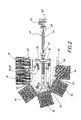
- FIG. 1 shows an embodiment of the device 10 for the production of transverse finned tubes.
- the device 10 has a base device 12 with two endless guideways 14, along which mold jaw halves 16 are moved adjacent to each other circumferentially. In FIG. 1 only two of these mold jaw halves 16 are shown.
- the two guideways 14 have a common forming section 18 and in each case a return path 20.
- the common forming section 18 and the respectively associated return path 20 are each connected by two deflecting sections 22 and 24.
- the deflecting sections 22 each have a deflecting element 26 and the deflecting sections 24 each have a deflecting element 28.
- the mold jaw halves 16, which adjoin one another closely along the respective guide track 14, are driven by means of a drive device 30.
- the drive device 30 has gears 32 which are provided with a toothing 34 (see FIG. FIG. 3 ), which is provided on the underside of the respective mold jaw halves.
- the respective deflecting member 26 and 28 is attached to a sliding element 36 which is mounted on a machine-fixed base member 38 is guided linearly movable, as from FIG. 3 is apparent.
- the linear mobility of the displacement element 36 with respect to the machine-fixed base element 38 is in FIG. 3 illustrated by the double arrow 40.
- the displacement element 36 and consequently the respectively associated deflection element 26 or 28 are connected to a compensation device 42.
- the compensation device 42 is dependent on the temperature and / or the speed of the mold jaw halves tolerance compensation of the along the associated guideway 14 rotating mold jaw halves 16 automatically compensated, so that it is not necessary to manually re-adjust the deflecting 26 or 28 time-consuming to accomplish a corresponding compensation.
- the respective compensation device 42 is formed by an air spring 44.
- the air spring 44 has a first connection fitting 46 and a second connection fitting 48. With the first connection fitting 46, the air spring 44 is connected to the displacement element 36.
- the second connection fitting 48 is connected to a machine-fixed console 50.
- the second connection fitting 48 has a compressed air connection 52.
- the compressed air connection 52 can be connected to a (not shown) compressed air source to pressurize the air spring 44 with compressed air of a defined overpressure. This results in a corresponding contraction of the air spring 44 between its connection fittings 46 and 48, i. a defined adjustment and tension of the first connection fitting 46 toward the machine-fixed second connection fitting 48th
- the respective deflection member 26 and 28 is preferably made of a low-wear plastic material having oil deposits to minimize the friction of the mold jaw halves 16 along the respective deflection member 26 and 28 respectively.
- the respective deflection member 26 and 28 is formed with a clothoid-like guide edge 54 to prevent a jumping movement of the mold jaw halves 16 in the transition region between the respective rectilinear return path 20, the respective deflecting member 26 and 28 and the common rectilinear section 18.
- the clothoid-like guide edge 54 is formed by a clothoid-like guide groove 56 which in the respective deflection member 26 and 28 is formed on the underside.
- the respective mold jaw half 16 has two guide rollers 58 which are adapted to the guide groove 56 of the respective deflecting member 26 and 28 free of play.
- a spring element 60 is also provided between the machine-fixed base member 38 and the displacement element 36 of the respective deflection member, which forms a part of the compensation device 42.
- FIGS. 1 to 3 each with the same reference numerals, so that it is unnecessary, in conjunction with these figures, to describe all the details in detail.
Landscapes
- Engineering & Computer Science (AREA)
- Mechanical Engineering (AREA)
- Manufacturing & Machinery (AREA)
- Moulds For Moulding Plastics Or The Like (AREA)
- Shaping Of Tube Ends By Bending Or Straightening (AREA)
- Finish Polishing, Edge Sharpening, And Grinding By Specific Grinding Devices (AREA)
- Body Structure For Vehicles (AREA)
- Preparation Of Compounds By Using Micro-Organisms (AREA)
- Paper (AREA)
- Fodder In General (AREA)
Claims (2)
- Dispositif de réalisation de tubes à nervures transversales avec des demi-empreintes (16) qui peuvent être déplacées dans le sens périphérique de manière adjacente le long de deux voies de guidage (14) chacune au moyen d'un dispositif d'entraînement (30) associé, les deux voies de guidage (14) comportant un tronçon commun (18), respectivement un tronçon de retour (20) et respectivement deux tronçons de renvoi (22 ; 24), le tronçon de renvoi (22 ; 24) respectif comportant un organe de renvoi (26 ; 28), qui est configuré avec un bord de guidage (54) courbe pour les demi-empreintes (16) et qui est monté de manière linéairement mobile sur un élément de base (38) solidaire de la machine et est relié à un dispositif de compensation (42), qui peut compenser un jeu de tolérances des demi-empreintes (16) tournant le long de la voie de guidage (14) associée,
caractérisé en ce que l'organe de renvoi (26 ; 28) respectif est réalisé dans une matière plastique à faible usure et le jeu de tolérances dépend de la température et/ou de la vitesse des demi-empreintes (16), en ce que l'organe de renvoi (26 ; 28) respectif est configuré avec un bord de guidage (54) en forme de clothoïde pour les demi-empreintes (16) associées, et en ce que le dispositif de compensation (42) comporte un amortisseur pneumatique (44) apte à être sollicité par air comprimé. - Dispositif selon la revendication 1, caractérisé en ce que la matière plastique comporte des inclusions d'huile.
Applications Claiming Priority (3)
| Application Number | Priority Date | Filing Date | Title |
|---|---|---|---|
| DE10257365A DE10257365B3 (de) | 2002-12-09 | 2002-12-09 | Vorrichtung zur Herstellung von Querrippenrohren |
| DE10257365 | 2002-12-09 | ||
| PCT/DE2003/003962 WO2004052625A1 (fr) | 2002-12-09 | 2003-12-02 | Dispositif pour produire des tubes a nervures transversales |
Publications (3)
| Publication Number | Publication Date |
|---|---|
| EP1569784A1 EP1569784A1 (fr) | 2005-09-07 |
| EP1569784B1 true EP1569784B1 (fr) | 2008-08-20 |
| EP1569784B8 EP1569784B8 (fr) | 2008-11-26 |
Family
ID=32240566
Family Applications (1)
| Application Number | Title | Priority Date | Filing Date |
|---|---|---|---|
| EP03788834A Expired - Lifetime EP1569784B8 (fr) | 2002-12-09 | 2003-12-02 | Dispositif pour produire des tubes a nervures transversales |
Country Status (11)
| Country | Link |
|---|---|
| US (1) | US7207791B2 (fr) |
| EP (1) | EP1569784B8 (fr) |
| CN (1) | CN100393503C (fr) |
| AT (1) | ATE405407T1 (fr) |
| AU (1) | AU2003292995A1 (fr) |
| CA (1) | CA2507063C (fr) |
| DE (2) | DE10257365B3 (fr) |
| ES (1) | ES2312841T3 (fr) |
| PT (1) | PT1569784E (fr) |
| RU (1) | RU2325280C2 (fr) |
| WO (1) | WO2004052625A1 (fr) |
Families Citing this family (5)
| Publication number | Priority date | Publication date | Assignee | Title |
|---|---|---|---|---|
| KR20140114345A (ko) | 2005-11-16 | 2014-09-26 | 앤드류 레오 해인즈 | 성형 장치 내 또는 관련 개량물 |
| DE102007049656A1 (de) * | 2007-10-12 | 2009-04-23 | Unicor Gmbh | Korrugatoreinrichtung mit Greifer |
| DE202008006455U1 (de) | 2008-04-28 | 2008-08-28 | Maintools Gmbh & Co.Kg | Formvorrichtung, insbesondere Corrugator, zum Herstellen von profilierten Kunststoffrohren |
| AU2009302979B2 (en) | 2008-10-07 | 2016-09-15 | Manufacturing Systems Limited | Forming methods |
| CA2852557C (fr) * | 2014-05-20 | 2022-04-05 | Manfred A. A. Lupke | Systeme et methode d'identification de problemes de dilatation thermique dans une onduleuse |
Family Cites Families (10)
| Publication number | Priority date | Publication date | Assignee | Title |
|---|---|---|---|---|
| US3280430A (en) * | 1965-05-24 | 1966-10-25 | Acme Hamilton Mfg Corp | Apparatus for making corrugated plastic tubing |
| DE2061027C3 (de) * | 1970-12-11 | 1982-03-04 | Wilhelm 8730 Bad Kissingen Hegler | Vorrichtung zum Anbringen einer Querprofilierung an einem Rohr aus thermoplastischem Kunststoff |
| DE3118932C3 (de) * | 1981-05-13 | 1995-02-09 | Wilhelm Hegler | Vorrichtung zur Herstellung von Kunststoffrohren mit Querrillen |
| US4439130A (en) * | 1981-11-23 | 1984-03-27 | Cullom Machine Tool & Die, Inc. | Plastic tile corrugator |
| US4725221A (en) * | 1986-05-23 | 1988-02-16 | John H. Blanz Company, Inc. | Improved machine for continuously producing an element of a separable fastener |
| US4824354A (en) * | 1988-02-16 | 1989-04-25 | Keaton Clyde D | Hydraulic continuous press with improved drive |
| US5111735A (en) * | 1990-10-30 | 1992-05-12 | Beloit Corporation | Air spring with quick release valve |
| DE19619429A1 (de) * | 1996-05-14 | 1997-12-04 | Trapp Roland Dipl Ing Fh | Teile einer Maschine zur kontinuierlichen Herstellung von radial- oder spiralförmig profilierten Rohren aus thermoplastischen Kunststoffen nach dem Blasformverfahren |
| DE19702638C1 (de) * | 1997-01-25 | 1998-02-26 | Unicor Rohrsysteme Gmbh | Vorrichtung zum Herstellen von Querrippen-Rohren |
| DE19922726A1 (de) * | 1999-05-18 | 2000-11-23 | Ralph Peter Hegler | Vorrichtung zur Herstellung von Kunststoff-Wellrohren |
-
2002
- 2002-12-09 DE DE10257365A patent/DE10257365B3/de not_active Expired - Fee Related
-
2003
- 2003-12-02 CN CNB2003801055232A patent/CN100393503C/zh not_active Expired - Fee Related
- 2003-12-02 WO PCT/DE2003/003962 patent/WO2004052625A1/fr not_active Ceased
- 2003-12-02 RU RU2005121532/11A patent/RU2325280C2/ru not_active IP Right Cessation
- 2003-12-02 DE DE50310386T patent/DE50310386D1/de not_active Expired - Lifetime
- 2003-12-02 ES ES03788834T patent/ES2312841T3/es not_active Expired - Lifetime
- 2003-12-02 AT AT03788834T patent/ATE405407T1/de active
- 2003-12-02 EP EP03788834A patent/EP1569784B8/fr not_active Expired - Lifetime
- 2003-12-02 AU AU2003292995A patent/AU2003292995A1/en not_active Abandoned
- 2003-12-02 PT PT03788834T patent/PT1569784E/pt unknown
- 2003-12-02 US US10/536,489 patent/US7207791B2/en not_active Expired - Fee Related
- 2003-12-02 CA CA2507063A patent/CA2507063C/fr not_active Expired - Lifetime
Also Published As
| Publication number | Publication date |
|---|---|
| CN1723114A (zh) | 2006-01-18 |
| CA2507063A1 (fr) | 2004-06-24 |
| RU2325280C2 (ru) | 2008-05-27 |
| US7207791B2 (en) | 2007-04-24 |
| CA2507063C (fr) | 2011-02-15 |
| ATE405407T1 (de) | 2008-09-15 |
| RU2005121532A (ru) | 2006-01-20 |
| US20060134256A1 (en) | 2006-06-22 |
| DE50310386D1 (de) | 2008-10-02 |
| PT1569784E (pt) | 2008-12-02 |
| AU2003292995A1 (en) | 2004-06-30 |
| WO2004052625A1 (fr) | 2004-06-24 |
| EP1569784A1 (fr) | 2005-09-07 |
| EP1569784B8 (fr) | 2008-11-26 |
| DE10257365B3 (de) | 2004-06-03 |
| ES2312841T3 (es) | 2009-03-01 |
| CN100393503C (zh) | 2008-06-11 |
Similar Documents
| Publication | Publication Date | Title |
|---|---|---|
| DE69008256T2 (de) | Vorrichtung zum Rillen und Schneiden endloser Bahnen aus Pappe und dergleichen. | |
| DE69511811T2 (de) | Förderanlage | |
| DE69517467T2 (de) | Kombinierte Formträger und Gestängevorrichtung | |
| DE69500513T2 (de) | Faserauflegevorrichtung, Pressgerät und Verfahren zum Auflegen und Kompaktieren von Faserstrangen | |
| EP0937568B1 (fr) | Dispositif de délimitation variable d'un canal d'écoulement plat et procédé d'extraction d'une bande de matière a géometrie variable | |
| DE2701480C3 (de) | Schrittweise arbeitende Vorrichtung zum Herstellen von Vorformkörpern | |
| EP0254028B1 (fr) | Dispositif d'étirage pour étirer continuellement un boudin de matériau en barres ou tubulaire | |
| EP2740677A1 (fr) | Installation de transport pour machine d'emballage par emboutissage | |
| DE19528751C2 (de) | Vorrichtung zum Verschieben einer Formaufspanneinheit zur Verwendung in Hohlkörperblasanlagen | |
| EP1569784B1 (fr) | Dispositif pour produire des tubes a nervures transversales | |
| EP1254014B1 (fr) | Dispositif de fabrication de tubes en plastique profiles | |
| DE69202389T2 (de) | Stauchanlage. | |
| DE102006019532A1 (de) | Thermoformmaschine | |
| EP3964465A1 (fr) | Dispositif de pliage pour une pièce découpée plane | |
| DE10045681A1 (de) | Kontinuierlich arbeitende Presse | |
| EP1015226A1 (fr) | Dispositif pour produire des corps creux en films plastiques a deformation thermoplastique | |
| EP3969257B1 (fr) | Retrait de retour et tendeur de chaîne d'une installation d'étirage de film comportant un retrait longitudinal | |
| EP2435198B1 (fr) | Serre-flan flexible pour installations de profilage continu | |
| DE19824741A1 (de) | Verfahren und Vorrichtung zur Herstellung von Bundlagern | |
| EP0999926B1 (fr) | Presse d'injection sans sommier | |
| AT409242B (de) | Glättwerk für eine materialbahn aus thermoplastischem kunststoff | |
| EP1569783B1 (fr) | Dispositif pour produire des tubes a nervures transversales | |
| EP1234644B1 (fr) | Presse de découpage pour séparer des éléments à partir d'un matériau plastique thermoformable | |
| DE102013110081A1 (de) | Transportrad sowie Transportsystem | |
| EP0728540A2 (fr) | Procédé et outil pour le formage de tÔle |
Legal Events
| Date | Code | Title | Description |
|---|---|---|---|
| PUAI | Public reference made under article 153(3) epc to a published international application that has entered the european phase |
Free format text: ORIGINAL CODE: 0009012 |
|
| 17P | Request for examination filed |
Effective date: 20050504 |
|
| AK | Designated contracting states |
Kind code of ref document: A1 Designated state(s): AT BE BG CH CY CZ DE DK EE ES FI FR GB GR HU IE IT LI LU MC NL PT RO SE SI SK TR |
|
| AX | Request for extension of the european patent |
Extension state: AL LT LV MK |
|
| DAX | Request for extension of the european patent (deleted) | ||
| GRAP | Despatch of communication of intention to grant a patent |
Free format text: ORIGINAL CODE: EPIDOSNIGR1 |
|
| GRAS | Grant fee paid |
Free format text: ORIGINAL CODE: EPIDOSNIGR3 |
|
| GRAA | (expected) grant |
Free format text: ORIGINAL CODE: 0009210 |
|
| AK | Designated contracting states |
Kind code of ref document: B1 Designated state(s): AT BE BG CH CY CZ DE DK EE ES FI FR GB GR HU IE IT LI LU MC NL PT RO SE SI SK TR |
|
| REG | Reference to a national code |
Ref country code: GB Ref legal event code: FG4D Free format text: NOT ENGLISH |
|
| REG | Reference to a national code |
Ref country code: CH Ref legal event code: EP |
|
| REG | Reference to a national code |
Ref country code: IE Ref legal event code: FG4D Free format text: LANGUAGE OF EP DOCUMENT: GERMAN |
|
| REF | Corresponds to: |
Ref document number: 50310386 Country of ref document: DE Date of ref document: 20081002 Kind code of ref document: P |
|
| RBV | Designated contracting states (corrected) |
Designated state(s): AT BE BG CH CY CZ DK EE ES FI FR GB GR HU IE IT LI LU MC NL PT RO SE SI SK TR |
|
| REG | Reference to a national code |
Ref country code: PT Ref legal event code: SC4A Free format text: AVAILABILITY OF NATIONAL TRANSLATION Effective date: 20081118 |
|
| REG | Reference to a national code |
Ref country code: SE Ref legal event code: TRGR |
|
| PG25 | Lapsed in a contracting state [announced via postgrant information from national office to epo] |
Ref country code: NL Free format text: LAPSE BECAUSE OF FAILURE TO SUBMIT A TRANSLATION OF THE DESCRIPTION OR TO PAY THE FEE WITHIN THE PRESCRIBED TIME-LIMIT Effective date: 20080820 |
|
| PG25 | Lapsed in a contracting state [announced via postgrant information from national office to epo] |
Ref country code: SI Free format text: LAPSE BECAUSE OF FAILURE TO SUBMIT A TRANSLATION OF THE DESCRIPTION OR TO PAY THE FEE WITHIN THE PRESCRIBED TIME-LIMIT Effective date: 20080820 Ref country code: FI Free format text: LAPSE BECAUSE OF FAILURE TO SUBMIT A TRANSLATION OF THE DESCRIPTION OR TO PAY THE FEE WITHIN THE PRESCRIBED TIME-LIMIT Effective date: 20080820 |
|
| REG | Reference to a national code |
Ref country code: ES Ref legal event code: FG2A Ref document number: 2312841 Country of ref document: ES Kind code of ref document: T3 |
|
| REG | Reference to a national code |
Ref country code: IE Ref legal event code: FD4D |
|
| PG25 | Lapsed in a contracting state [announced via postgrant information from national office to epo] |
Ref country code: BG Free format text: LAPSE BECAUSE OF FAILURE TO SUBMIT A TRANSLATION OF THE DESCRIPTION OR TO PAY THE FEE WITHIN THE PRESCRIBED TIME-LIMIT Effective date: 20081120 Ref country code: DK Free format text: LAPSE BECAUSE OF FAILURE TO SUBMIT A TRANSLATION OF THE DESCRIPTION OR TO PAY THE FEE WITHIN THE PRESCRIBED TIME-LIMIT Effective date: 20080820 Ref country code: IE Free format text: LAPSE BECAUSE OF FAILURE TO SUBMIT A TRANSLATION OF THE DESCRIPTION OR TO PAY THE FEE WITHIN THE PRESCRIBED TIME-LIMIT Effective date: 20080820 |
|
| PG25 | Lapsed in a contracting state [announced via postgrant information from national office to epo] |
Ref country code: RO Free format text: LAPSE BECAUSE OF FAILURE TO SUBMIT A TRANSLATION OF THE DESCRIPTION OR TO PAY THE FEE WITHIN THE PRESCRIBED TIME-LIMIT Effective date: 20080820 Ref country code: SK Free format text: LAPSE BECAUSE OF FAILURE TO SUBMIT A TRANSLATION OF THE DESCRIPTION OR TO PAY THE FEE WITHIN THE PRESCRIBED TIME-LIMIT Effective date: 20080820 |
|
| PLBE | No opposition filed within time limit |
Free format text: ORIGINAL CODE: 0009261 |
|
| STAA | Information on the status of an ep patent application or granted ep patent |
Free format text: STATUS: NO OPPOSITION FILED WITHIN TIME LIMIT |
|
| BERE | Be: lapsed |
Owner name: UNICOR G.M.B.H. Effective date: 20081231 |
|
| 26N | No opposition filed |
Effective date: 20090525 |
|
| PG25 | Lapsed in a contracting state [announced via postgrant information from national office to epo] |
Ref country code: EE Free format text: LAPSE BECAUSE OF FAILURE TO SUBMIT A TRANSLATION OF THE DESCRIPTION OR TO PAY THE FEE WITHIN THE PRESCRIBED TIME-LIMIT Effective date: 20080820 Ref country code: MC Free format text: LAPSE BECAUSE OF NON-PAYMENT OF DUE FEES Effective date: 20081231 |
|
| REG | Reference to a national code |
Ref country code: CH Ref legal event code: PL |
|
| PG25 | Lapsed in a contracting state [announced via postgrant information from national office to epo] |
Ref country code: BE Free format text: LAPSE BECAUSE OF NON-PAYMENT OF DUE FEES Effective date: 20081231 |
|
| PG25 | Lapsed in a contracting state [announced via postgrant information from national office to epo] |
Ref country code: CH Free format text: LAPSE BECAUSE OF NON-PAYMENT OF DUE FEES Effective date: 20081231 Ref country code: LI Free format text: LAPSE BECAUSE OF NON-PAYMENT OF DUE FEES Effective date: 20081231 |
|
| PG25 | Lapsed in a contracting state [announced via postgrant information from national office to epo] |
Ref country code: LU Free format text: LAPSE BECAUSE OF NON-PAYMENT OF DUE FEES Effective date: 20081202 Ref country code: HU Free format text: LAPSE BECAUSE OF FAILURE TO SUBMIT A TRANSLATION OF THE DESCRIPTION OR TO PAY THE FEE WITHIN THE PRESCRIBED TIME-LIMIT Effective date: 20090221 Ref country code: CY Free format text: LAPSE BECAUSE OF FAILURE TO SUBMIT A TRANSLATION OF THE DESCRIPTION OR TO PAY THE FEE WITHIN THE PRESCRIBED TIME-LIMIT Effective date: 20080820 |
|
| PG25 | Lapsed in a contracting state [announced via postgrant information from national office to epo] |
Ref country code: GR Free format text: LAPSE BECAUSE OF FAILURE TO SUBMIT A TRANSLATION OF THE DESCRIPTION OR TO PAY THE FEE WITHIN THE PRESCRIBED TIME-LIMIT Effective date: 20081121 |
|
| PGFP | Annual fee paid to national office [announced via postgrant information from national office to epo] |
Ref country code: GB Payment date: 20131217 Year of fee payment: 11 Ref country code: AT Payment date: 20131216 Year of fee payment: 11 Ref country code: PT Payment date: 20130603 Year of fee payment: 11 Ref country code: SE Payment date: 20131217 Year of fee payment: 11 |
|
| PGFP | Annual fee paid to national office [announced via postgrant information from national office to epo] |
Ref country code: TR Payment date: 20131120 Year of fee payment: 11 Ref country code: ES Payment date: 20131216 Year of fee payment: 11 |
|
| PGFP | Annual fee paid to national office [announced via postgrant information from national office to epo] |
Ref country code: CZ Payment date: 20141125 Year of fee payment: 12 |
|
| PGFP | Annual fee paid to national office [announced via postgrant information from national office to epo] |
Ref country code: FR Payment date: 20141212 Year of fee payment: 12 |
|
| REG | Reference to a national code |
Ref country code: PT Ref legal event code: MM4A Free format text: LAPSE DUE TO NON-PAYMENT OF FEES Effective date: 20150602 |
|
| PG25 | Lapsed in a contracting state [announced via postgrant information from national office to epo] |
Ref country code: SE Free format text: LAPSE BECAUSE OF NON-PAYMENT OF DUE FEES Effective date: 20141203 Ref country code: PT Free format text: LAPSE BECAUSE OF NON-PAYMENT OF DUE FEES Effective date: 20150602 |
|
| REG | Reference to a national code |
Ref country code: SE Ref legal event code: EUG |
|
| REG | Reference to a national code |
Ref country code: AT Ref legal event code: MM01 Ref document number: 405407 Country of ref document: AT Kind code of ref document: T Effective date: 20141202 |
|
| GBPC | Gb: european patent ceased through non-payment of renewal fee |
Effective date: 20141202 |
|
| PG25 | Lapsed in a contracting state [announced via postgrant information from national office to epo] |
Ref country code: GB Free format text: LAPSE BECAUSE OF NON-PAYMENT OF DUE FEES Effective date: 20141202 |
|
| PG25 | Lapsed in a contracting state [announced via postgrant information from national office to epo] |
Ref country code: AT Free format text: LAPSE BECAUSE OF NON-PAYMENT OF DUE FEES Effective date: 20141202 |
|
| REG | Reference to a national code |
Ref country code: ES Ref legal event code: FD2A Effective date: 20160128 |
|
| PG25 | Lapsed in a contracting state [announced via postgrant information from national office to epo] |
Ref country code: ES Free format text: LAPSE BECAUSE OF NON-PAYMENT OF DUE FEES Effective date: 20141203 |
|
| PG25 | Lapsed in a contracting state [announced via postgrant information from national office to epo] |
Ref country code: CZ Free format text: LAPSE BECAUSE OF NON-PAYMENT OF DUE FEES Effective date: 20151202 |
|
| PGFP | Annual fee paid to national office [announced via postgrant information from national office to epo] |
Ref country code: IT Payment date: 20151222 Year of fee payment: 13 |
|
| REG | Reference to a national code |
Ref country code: FR Ref legal event code: ST Effective date: 20160831 |
|
| PG25 | Lapsed in a contracting state [announced via postgrant information from national office to epo] |
Ref country code: FR Free format text: LAPSE BECAUSE OF NON-PAYMENT OF DUE FEES Effective date: 20151231 |
|
| PG25 | Lapsed in a contracting state [announced via postgrant information from national office to epo] |
Ref country code: TR Free format text: LAPSE BECAUSE OF NON-PAYMENT OF DUE FEES Effective date: 20151202 |
|
| PG25 | Lapsed in a contracting state [announced via postgrant information from national office to epo] |
Ref country code: IT Free format text: LAPSE BECAUSE OF NON-PAYMENT OF DUE FEES Effective date: 20161202 |