EP1569553B1 - Skin wound mapping system and method - Google Patents
Skin wound mapping system and method Download PDFInfo
- Publication number
- EP1569553B1 EP1569553B1 EP03786187A EP03786187A EP1569553B1 EP 1569553 B1 EP1569553 B1 EP 1569553B1 EP 03786187 A EP03786187 A EP 03786187A EP 03786187 A EP03786187 A EP 03786187A EP 1569553 B1 EP1569553 B1 EP 1569553B1
- Authority
- EP
- European Patent Office
- Prior art keywords
- electrode
- test
- wound
- electrodes
- tissue
- Prior art date
- Legal status (The legal status is an assumption and is not a legal conclusion. Google has not performed a legal analysis and makes no representation as to the accuracy of the status listed.)
- Expired - Lifetime
Links
- 238000013507 mapping Methods 0.000 title claims abstract description 11
- 238000000034 method Methods 0.000 title claims description 49
- 206010072170 Skin wound Diseases 0.000 title claims description 7
- 238000012360 testing method Methods 0.000 claims abstract description 71
- 208000027418 Wounds and injury Diseases 0.000 claims description 91
- 238000005259 measurement Methods 0.000 claims description 20
- 239000000017 hydrogel Substances 0.000 claims description 19
- 239000011810 insulating material Substances 0.000 claims 6
- 230000000007 visual effect Effects 0.000 claims 2
- 238000011835 investigation Methods 0.000 abstract description 4
- 206010052428 Wound Diseases 0.000 description 78
- 210000001519 tissue Anatomy 0.000 description 37
- 210000003491 skin Anatomy 0.000 description 29
- 239000000758 substrate Substances 0.000 description 12
- 230000035876 healing Effects 0.000 description 10
- 208000014674 injury Diseases 0.000 description 9
- 210000000434 stratum corneum Anatomy 0.000 description 9
- 238000004364 calculation method Methods 0.000 description 7
- 210000004027 cell Anatomy 0.000 description 7
- 230000029663 wound healing Effects 0.000 description 7
- 238000003491 array Methods 0.000 description 6
- 238000012544 monitoring process Methods 0.000 description 6
- 230000006378 damage Effects 0.000 description 5
- 210000002615 epidermis Anatomy 0.000 description 5
- 230000008569 process Effects 0.000 description 5
- 238000002560 therapeutic procedure Methods 0.000 description 5
- 210000004204 blood vessel Anatomy 0.000 description 4
- 238000010586 diagram Methods 0.000 description 4
- 230000000694 effects Effects 0.000 description 4
- 239000000499 gel Substances 0.000 description 4
- 230000001225 therapeutic effect Effects 0.000 description 4
- 230000008733 trauma Effects 0.000 description 4
- 102000008186 Collagen Human genes 0.000 description 3
- 108010035532 Collagen Proteins 0.000 description 3
- BQCADISMDOOEFD-UHFFFAOYSA-N Silver Chemical compound [Ag] BQCADISMDOOEFD-UHFFFAOYSA-N 0.000 description 3
- 206010047139 Vasoconstriction Diseases 0.000 description 3
- 230000008901 benefit Effects 0.000 description 3
- 229920001436 collagen Polymers 0.000 description 3
- 210000004207 dermis Anatomy 0.000 description 3
- 230000023597 hemostasis Effects 0.000 description 3
- 238000002847 impedance measurement Methods 0.000 description 3
- 238000004519 manufacturing process Methods 0.000 description 3
- 239000000463 material Substances 0.000 description 3
- 238000013178 mathematical model Methods 0.000 description 3
- 230000035755 proliferation Effects 0.000 description 3
- 238000011160 research Methods 0.000 description 3
- 239000000523 sample Substances 0.000 description 3
- 229910052709 silver Inorganic materials 0.000 description 3
- 239000004332 silver Substances 0.000 description 3
- 238000011282 treatment Methods 0.000 description 3
- 230000025033 vasoconstriction Effects 0.000 description 3
- ZKHQWZAMYRWXGA-KQYNXXCUSA-J ATP(4-) Chemical compound C1=NC=2C(N)=NC=NC=2N1[C@@H]1O[C@H](COP([O-])(=O)OP([O-])(=O)OP([O-])([O-])=O)[C@@H](O)[C@H]1O ZKHQWZAMYRWXGA-KQYNXXCUSA-J 0.000 description 2
- ZKHQWZAMYRWXGA-UHFFFAOYSA-N Adenosine triphosphate Natural products C1=NC=2C(N)=NC=NC=2N1C1OC(COP(O)(=O)OP(O)(=O)OP(O)(O)=O)C(O)C1O ZKHQWZAMYRWXGA-UHFFFAOYSA-N 0.000 description 2
- NTYJJOPFIAHURM-UHFFFAOYSA-N Histamine Chemical compound NCCC1=CN=CN1 NTYJJOPFIAHURM-UHFFFAOYSA-N 0.000 description 2
- 206010061218 Inflammation Diseases 0.000 description 2
- 239000000853 adhesive Substances 0.000 description 2
- 230000001070 adhesive effect Effects 0.000 description 2
- 230000004888 barrier function Effects 0.000 description 2
- 230000015572 biosynthetic process Effects 0.000 description 2
- 210000004369 blood Anatomy 0.000 description 2
- 239000008280 blood Substances 0.000 description 2
- 239000003990 capacitor Substances 0.000 description 2
- 239000004020 conductor Substances 0.000 description 2
- 239000013256 coordination polymer Substances 0.000 description 2
- 230000005684 electric field Effects 0.000 description 2
- 238000000157 electrochemical-induced impedance spectroscopy Methods 0.000 description 2
- 210000002950 fibroblast Anatomy 0.000 description 2
- 230000012010 growth Effects 0.000 description 2
- 239000003102 growth factor Substances 0.000 description 2
- 230000036541 health Effects 0.000 description 2
- 230000004054 inflammatory process Effects 0.000 description 2
- 210000002540 macrophage Anatomy 0.000 description 2
- 239000011159 matrix material Substances 0.000 description 2
- 230000035800 maturation Effects 0.000 description 2
- 210000001616 monocyte Anatomy 0.000 description 2
- 210000000440 neutrophil Anatomy 0.000 description 2
- 210000000056 organ Anatomy 0.000 description 2
- 230000035515 penetration Effects 0.000 description 2
- 230000010118 platelet activation Effects 0.000 description 2
- 230000004224 protection Effects 0.000 description 2
- 238000007650 screen-printing Methods 0.000 description 2
- QZAYGJVTTNCVMB-UHFFFAOYSA-N serotonin Chemical compound C1=C(O)C=C2C(CCN)=CNC2=C1 QZAYGJVTTNCVMB-UHFFFAOYSA-N 0.000 description 2
- 239000000126 substance Substances 0.000 description 2
- XLYOFNOQVPJJNP-UHFFFAOYSA-N water Substances O XLYOFNOQVPJJNP-UHFFFAOYSA-N 0.000 description 2
- QTBSBXVTEAMEQO-UHFFFAOYSA-M Acetate Chemical compound CC([O-])=O QTBSBXVTEAMEQO-UHFFFAOYSA-M 0.000 description 1
- 241000894006 Bacteria Species 0.000 description 1
- 206010063560 Excessive granulation tissue Diseases 0.000 description 1
- 206010015866 Extravasation Diseases 0.000 description 1
- QZXATCCPQKOEIH-UHFFFAOYSA-N Florasulam Chemical compound N=1N2C(OC)=NC=C(F)C2=NC=1S(=O)(=O)NC1=C(F)C=CC=C1F QZXATCCPQKOEIH-UHFFFAOYSA-N 0.000 description 1
- 229910021607 Silver chloride Inorganic materials 0.000 description 1
- 238000005299 abrasion Methods 0.000 description 1
- 230000004913 activation Effects 0.000 description 1
- 229960001456 adenosine triphosphate Drugs 0.000 description 1
- 238000013019 agitation Methods 0.000 description 1
- 238000005267 amalgamation Methods 0.000 description 1
- 238000004458 analytical method Methods 0.000 description 1
- 238000013459 approach Methods 0.000 description 1
- QVGXLLKOCUKJST-UHFFFAOYSA-N atomic oxygen Chemical compound [O] QVGXLLKOCUKJST-UHFFFAOYSA-N 0.000 description 1
- 230000033228 biological regulation Effects 0.000 description 1
- 230000000740 bleeding effect Effects 0.000 description 1
- 230000023555 blood coagulation Effects 0.000 description 1
- 239000012503 blood component Substances 0.000 description 1
- 210000004556 brain Anatomy 0.000 description 1
- 230000001413 cellular effect Effects 0.000 description 1
- 238000012512 characterization method Methods 0.000 description 1
- 239000003086 colorant Substances 0.000 description 1
- 239000000306 component Substances 0.000 description 1
- 210000002808 connective tissue Anatomy 0.000 description 1
- 238000010276 construction Methods 0.000 description 1
- 239000000356 contaminant Substances 0.000 description 1
- 230000008602 contraction Effects 0.000 description 1
- 238000012937 correction Methods 0.000 description 1
- 230000001419 dependent effect Effects 0.000 description 1
- 230000000994 depressogenic effect Effects 0.000 description 1
- 201000010099 disease Diseases 0.000 description 1
- 208000037265 diseases, disorders, signs and symptoms Diseases 0.000 description 1
- 238000009826 distribution Methods 0.000 description 1
- 229940079593 drug Drugs 0.000 description 1
- 239000003814 drug Substances 0.000 description 1
- 238000012377 drug delivery Methods 0.000 description 1
- 230000002500 effect on skin Effects 0.000 description 1
- 230000005672 electromagnetic field Effects 0.000 description 1
- 210000003038 endothelium Anatomy 0.000 description 1
- 238000005516 engineering process Methods 0.000 description 1
- 210000000981 epithelium Anatomy 0.000 description 1
- 230000036251 extravasation Effects 0.000 description 1
- 238000001914 filtration Methods 0.000 description 1
- 239000012530 fluid Substances 0.000 description 1
- 239000006260 foam Substances 0.000 description 1
- 230000006870 function Effects 0.000 description 1
- 210000001126 granulation tissue Anatomy 0.000 description 1
- 230000036074 healthy skin Effects 0.000 description 1
- 229960001340 histamine Drugs 0.000 description 1
- 150000004677 hydrates Chemical class 0.000 description 1
- 238000003384 imaging method Methods 0.000 description 1
- 230000001900 immune effect Effects 0.000 description 1
- 230000036039 immunity Effects 0.000 description 1
- 230000006872 improvement Effects 0.000 description 1
- 230000002757 inflammatory effect Effects 0.000 description 1
- 150000002500 ions Chemical class 0.000 description 1
- 230000001788 irregular Effects 0.000 description 1
- 208000028867 ischemia Diseases 0.000 description 1
- 230000007257 malfunction Effects 0.000 description 1
- 244000005700 microbiome Species 0.000 description 1
- 239000000203 mixture Substances 0.000 description 1
- 230000004048 modification Effects 0.000 description 1
- 238000012986 modification Methods 0.000 description 1
- 210000000651 myofibroblast Anatomy 0.000 description 1
- 235000015097 nutrients Nutrition 0.000 description 1
- 229910052760 oxygen Inorganic materials 0.000 description 1
- 239000001301 oxygen Substances 0.000 description 1
- 244000052769 pathogen Species 0.000 description 1
- 231100000915 pathological change Toxicity 0.000 description 1
- 230000036285 pathological change Effects 0.000 description 1
- 230000001575 pathological effect Effects 0.000 description 1
- 230000037361 pathway Effects 0.000 description 1
- 238000000059 patterning Methods 0.000 description 1
- 230000002093 peripheral effect Effects 0.000 description 1
- 229920000728 polyester Polymers 0.000 description 1
- 102000004169 proteins and genes Human genes 0.000 description 1
- 108090000623 proteins and genes Proteins 0.000 description 1
- 238000009877 rendering Methods 0.000 description 1
- 231100000241 scar Toxicity 0.000 description 1
- 229940076279 serotonin Drugs 0.000 description 1
- HKZLPVFGJNLROG-UHFFFAOYSA-M silver monochloride Chemical compound [Cl-].[Ag+] HKZLPVFGJNLROG-UHFFFAOYSA-M 0.000 description 1
- 230000004936 stimulating effect Effects 0.000 description 1
- 238000007920 subcutaneous administration Methods 0.000 description 1
- 239000010409 thin film Substances 0.000 description 1
- 230000009772 tissue formation Effects 0.000 description 1
- 230000017423 tissue regeneration Effects 0.000 description 1
- 230000037314 wound repair Effects 0.000 description 1
- 230000037303 wrinkles Effects 0.000 description 1
Images


Classifications
-
- A—HUMAN NECESSITIES
- A61—MEDICAL OR VETERINARY SCIENCE; HYGIENE
- A61B—DIAGNOSIS; SURGERY; IDENTIFICATION
- A61B5/00—Measuring for diagnostic purposes; Identification of persons
- A61B5/44—Detecting, measuring or recording for evaluating the integumentary system, e.g. skin, hair or nails
- A61B5/441—Skin evaluation, e.g. for skin disorder diagnosis
- A61B5/445—Evaluating skin irritation or skin trauma, e.g. rash, eczema, wound, bed sore
-
- A—HUMAN NECESSITIES
- A61—MEDICAL OR VETERINARY SCIENCE; HYGIENE
- A61B—DIAGNOSIS; SURGERY; IDENTIFICATION
- A61B5/00—Measuring for diagnostic purposes; Identification of persons
- A61B5/05—Detecting, measuring or recording for diagnosis by means of electric currents or magnetic fields; Measuring using microwaves or radio waves
- A61B5/053—Measuring electrical impedance or conductance of a portion of the body
- A61B5/0531—Measuring skin impedance
-
- A—HUMAN NECESSITIES
- A61—MEDICAL OR VETERINARY SCIENCE; HYGIENE
- A61N—ELECTROTHERAPY; MAGNETOTHERAPY; RADIATION THERAPY; ULTRASOUND THERAPY
- A61N1/00—Electrotherapy; Circuits therefor
- A61N1/02—Details
- A61N1/04—Electrodes
- A61N1/0404—Electrodes for external use
- A61N1/0408—Use-related aspects
- A61N1/0428—Specially adapted for iontophoresis, e.g. AC, DC or including drug reservoirs
- A61N1/0432—Anode and cathode
- A61N1/044—Shape of the electrode
-
- A—HUMAN NECESSITIES
- A61—MEDICAL OR VETERINARY SCIENCE; HYGIENE
- A61N—ELECTROTHERAPY; MAGNETOTHERAPY; RADIATION THERAPY; ULTRASOUND THERAPY
- A61N1/00—Electrotherapy; Circuits therefor
- A61N1/18—Applying electric currents by contact electrodes
- A61N1/32—Applying electric currents by contact electrodes alternating or intermittent currents
- A61N1/325—Applying electric currents by contact electrodes alternating or intermittent currents for iontophoresis, i.e. transfer of media in ionic state by an electromotoric force into the body
-
- A—HUMAN NECESSITIES
- A61—MEDICAL OR VETERINARY SCIENCE; HYGIENE
- A61B—DIAGNOSIS; SURGERY; IDENTIFICATION
- A61B2562/00—Details of sensors; Constructional details of sensor housings or probes; Accessories for sensors
- A61B2562/02—Details of sensors specially adapted for in-vivo measurements
- A61B2562/0209—Special features of electrodes classified in A61B5/24, A61B5/25, A61B5/283, A61B5/291, A61B5/296, A61B5/053
- A61B2562/0215—Silver or silver chloride containing
-
- A—HUMAN NECESSITIES
- A61—MEDICAL OR VETERINARY SCIENCE; HYGIENE
- A61B—DIAGNOSIS; SURGERY; IDENTIFICATION
- A61B2562/00—Details of sensors; Constructional details of sensor housings or probes; Accessories for sensors
- A61B2562/04—Arrangements of multiple sensors of the same type
- A61B2562/046—Arrangements of multiple sensors of the same type in a matrix array
-
- A—HUMAN NECESSITIES
- A61—MEDICAL OR VETERINARY SCIENCE; HYGIENE
- A61N—ELECTROTHERAPY; MAGNETOTHERAPY; RADIATION THERAPY; ULTRASOUND THERAPY
- A61N1/00—Electrotherapy; Circuits therefor
- A61N1/02—Details
- A61N1/04—Electrodes
- A61N1/0404—Electrodes for external use
- A61N1/0408—Use-related aspects
- A61N1/0428—Specially adapted for iontophoresis, e.g. AC, DC or including drug reservoirs
- A61N1/0432—Anode and cathode
- A61N1/0436—Material of the electrode
Definitions
- This invention relates to a system and method for monitoring a skin wound .
- Wound measurement appears to be the only method clinicians have in determining the state of a wound or to assess the effectiveness of a given treatment or dressing, indeed it has been reported that in clinical trials, wound area is the most commonly reported property of wounds 1 . Although current methods are numerous, almost all are simple and most are subjective, bringing their accuracy into question.
- the most frequency used techniques are two-dimensional and include linear measurements, wound tracing, planimetry, and stereophotogrammetry.
- Linear measurements are perhaps the most simple and involve length and width measurements, taken at the longest length of the wound and the widest width, measured perpendicular to the length axis 2 using a wound gauge or ruler. While clearly quick and Inexpensive this method is very subjective and will therefore result in a certain degree of inaccuracy.
- a second linear measurement often used in the assessment of wounds is that of area.
- Several manufacturers to the health care industry have produced a gauge with concentric circles which can be used to estimate wound area.
- this method will introduce a large amount of error into the result.
- Even in cases where symmetry is evident, subjective identification of the wound boundary can cause inaccuracies in this method.
- Planimetry, wound tracing or the acetate method is the technique which employs the use of metric graph paper with a 4cm grid size where the complete squares within the traced wound area are counted and the result indicated in square centimetres 2 .
- a further 2-dimensional technique used to determine wound parameters is that of stereophotogrammetry, a more complex and expensive method involving the use of a video camera attached to a computer with appropriate software.
- the wound is captured on video after a target plate has been placed on the plane of the affected area.
- the target plate allows correct orientation and distortion correction in order to obtain a true image of the wound before it is downloaded to the computer.
- the wound area can then be traced from the displayed image and the software calculates the wound length, width and area 2 .
- An accurate, atraumatic mapping technique would have the very attractive advantage of enabling scientific assessment of the efficacy of various treatments claimed to promote/enhance wound healing and the unequivocal identification of those most effective.
- the skin has several functions including temperature regulation, immunity and protection and when the integrity of the skin is comprised by trauma it is said to be wounded.
- Wounds vary in severity and this is gauged mainly by the depth or penetration of the injury and the skin layers involved. Minor abrasions where the portion of skin lost does not extend beyond the epidermis into the dermis is defined as an epidermal wound, while deep wounds are injuries where substantial tissue loss is evident into the lower dermal layers.
- the healing process can be divided into 4 sequential but not distinct phases, haemostasis, inflammation, proliferation and maturation.
- Haemostasis is the process of stopping bleeding 4 which is a common occurrence in deep tissue trauma; following injury a discharge of blood or fluid from a vessel in the surrounding tissue (extravasation) initiates blood clotting and platelet activation. It is this platelet activation which triggers haemostasis, vasoconstriction and new tissue formation to aid in wound repair.
- the vasoconstriction is a result of the release of a series of chemical mediators such as histamine, serotonin and adenosine triphosphate (ATP). Their role is to attract the circulating leucocytes (colourless blood component which protects against micro organisms) to the site of impact 4 .
- the onset of vasoconstriction also coincides with the start of the second or inflammatory phase.
- the increased volume of 'local' blood allows plasma to leak to the surrounding tissue thus swe0ing them, hence inflammation.
- Neutrophils and monocytes arrive at the wound dormant and on activation the neutrophils set about removing any offensive bacteria while the monocytes become macrophages producing growth factors to accelerate the healing process. Macrophages themselves also phagocytose pathogenic organisms and clear tissue debris. The last stage of this phase sees the released growth factors stimulating endothelium to oversee the growth of newly formed blood vessels.
- the third stage, the proliferation phase is the growth and reproduction of tissue, namely connective or granulation tissue whose formation is dependent on the newly formed blood vessel.
- the blood vessels provide a suitable environment for tissue regeneration by providing nutrients and oxygen for the cells.
- fibroblasts create a network of collagen fibres in the wound bed and produce a sticky substance, proteoglycan which fills the tissue bed binding the fibres together to form a stable framework.
- Epithelialisation and contraction are the final processes in this stage whereby the wound regenerates epithelium from the outer edges of the wound towards the centre.
- the cells migrate across the surface to they meet and at the same time the wound is contracted by myofibroblasts.
- the fourth and final phase of the healing process is the maturation phase which can be several weeks from the time of injury and involves the remodelling of the collagen-fibres laid down in the proliferation phase 4 .
- This collagen is soft and gelatinous and is replaced in this stage by more orderly and stronger collagen.
- the final act in the healing process is the removal of fibroblasts from the wound site and the restructuring of blood vessels away from the area which results in the shrinking and paling of the scar tissue 4 .
- the skin is made up of 3 main layers: - the subcutaneous layer, the dermis, and the epidermis (the strongest layer) 5 .
- the epidermis the outermost layer, is in direct contact with the environment and therefore provides a protection barrier to outside materials (products, water, etc.) as well as filtering sunlight. Unlike any other organ of the body, the epidermis is self-renewing and hence replaces itself continually 6 .
- the epidermis can be sub-divided into several further layers with the stratum corneum forming the outermost layer.
- Cells in the underlying basal layer are constantly multiplying and undergo changes as they push up towards the skin's surface. As these cells become flattened, compacted and dehydrated, they lose their nuclei and develop a hardening protein, eventually forming the stratum corneum. The dead cells on the surface are continuously being shed, replaced by the cells migrating from the underlying layers 7 .
- the stratum corneum consists of several layers of dead cells and varies in thickness depending on location on the body, the thickest layers being on the palms of the hand and the bottom of the feet.
- the stratum corneum becomes thicker with age and exposure to the elements making it more susceptible to wrinkles and creases 5 .
- the tissues underlying the skin are conductive and can be represented by a resistance, R T , in series with the above parallel combination 9 .
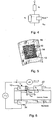
- the equivalent circuit model is shown in Figure 1 . This equivalent circuit model comprising simple resistances and a capacitance is obviously a simplification of the skin's complex electrical properties.
- the impedance of the capacitance tends to zero and the overall impedance approaches that of R T .
- the impedance of the capacitance tends to infinity and current therefore flows through the series combination of R T and R P and the overall impedance is generally therefore much larger than the high frequency case.
- the impedance locus of the 'classical' model (equivalent circuit incorporating a resistance and capacitance in parallel) should consist of a semi- circular arc whose centre is located exactly on the real axis, as shown on Figure 2 .
- Figure 3 shows the typical form of a measured impedance locus plot of the electrode-skin interface, demonstrating that the simple model described above is not adequate to fully characterise the electrical properties of the skin.
- R inf and R o the intercepts with the real axis at high and low frequencies respectively, are the high and low frequency limit resistances.
- the impedance locus is a semi-circular arc whose centre lies on the real axis with a frequency intercept angle ⁇ of 90°.
- the locus takes the form of a 'depressed' semi-circufar arc whose centre lies below the real axis and the frequency intercept angle ⁇ is less than 90°.
- Mapping for example, the low-frequency impedance of skin sites in and around a wound site will evidence clearly the major differences between healthy skin (high impedance) and the wound (low impedance).
- WO 99/23945 discloses a skin impedance imaging system which comprises a probe having multiple stationary electrodes applied to a patient's skin.
- a reference electrode is applied to the patient's skin and an alternating current is supplied to the probe and/or reference electrode so the current flows through the patient's skin.
- An alternating current supply and a device for measuring voltage changes are provided so that a measure of the impedance of the skin can be obtained, thereby providing an indication of the induced or pathological changes in the skin.
- An image of the impedance changes across various areas of the skin can be produced.
- a skin wound monitoring system as specified in claim 1.
- a method of monitoring a skin wound as specified in claim 15.
- An embodiment of the invention involves the use of a 'smart' wound dressing which can be used to monitor the skin's electrical impedance and thus to assess the size, shape, depth and composition of the wound, all without the need of removing the dressing.
- the principle of this embodiment is illustrated diagrammatically in Figure 5 , where the electrode connecting leads are omitted for clarity.
- test electrodes 10 incorporated in a wound dressing 12
- the individual impedances of the tissue underlying each test electrode 10 can be used to create a two-dimensional map of the wound. If a sufficient number of small area electrodes are used, the shape and size of the wound can be ascertained from the measured impedance values. Over time, changes in the wound shape and size can be followed using this technique.
- the use of a multi-electrode array enables the monitoring of different sites without the need to move a single electrode from one measurement site to the next.
- Hydrogel is presently used as a wound dressing as it protects the wound bed from foreign contaminants, and hydrates and enhances the environment essential to thorough wound healing. Hydrogels can also be used in the construction of bio-impedance monitoring electrodes and, along with the use of screen printing or similar technologies, lend themselves to the fabrication of accurate, flexible, low-profile electrode arrays. The test electrodes can therefore be incorporated into a hydrogel-based wound dressing and used to monitor the wound and the effect of therapy without the need to remove the dressing. A significant improvement on current techniques is that this system does not interfere with the wound bed. As the preferred embodiment is designed to be used as part of, or to constitute, the wound dressing, it allows new tissue formed as part of the healing process, to remain undisturbed while the wound is being assessed. In addition to calculating the wound area, this device is also effectively assisting-wound healing.
- the invention maps the wound direct from the site and produces an image, complete with calculations of area, tissue type etc., on a computer screen with little involvement from the clinician required, therefore reducing subjectivity and error.
- tissue type present in the wound bed. It is possible to model the electrical properties of tissues with mathematical and/or equivalent electrical circuits. With the correct choice of mathematical or equivalent circuit model, it is possible to relate the model elements to the underlying physical processes and thus study the healing processes and meaningfully assess the efficacy of a range of therapies.
- the invention therefore allows a clinician to characterise tissue and hence evaluates the tissue type present under the individual electrodes incorporated in the dressing. This information can then be used to establish the state of the wound.
- test electrodes can be used to apply the desired 'electrotherapeutic' signals and to evaluate their effects, all without removing the dressing.
- the test electrodes can also be used for iontophoretic drug delivery and assessment of resultant therapeutic effect or tissue trauma.
- a rectangular 5 x 5 array of test electrodes 10 is screen printed onto a thin flexible insulating substrate 18, each test electrode 10 having a respective lead 20 also screen printed on the substrate. Screen printing enables the accurate patterning and positioning of the electrodes and their associated leads.
- the leads 20 are preferably formed using a conductive material such as a serigraphic silver-loaded ink (e.g. PF-410 silver conductive ink from Norcote, England) and the test electrodes 10 are preferably formed using a serigraphic silver/silver chloride-loaded ink to ensure good electrical performance at the electrode-gel interface (e.g. Part No. 5874 from Dupont, Bristol, England). Other materials may be used if the electrodes are also to be used apply iontophoretic or other therapeutic electrical signals as will be described. All twenty-five test electrode leads 20 are brought together at a projecting connector edge 26 of the substrate 18.
- a serigraphic silver-loaded ink e.g. PF-410 silver conductive ink from Norcote,
- a number of reference electrodes 22 are also screen printed on the substrate 18.
- six substantially parallel strip-like reference electrodes 22 are provided, four of which extend each between a respective pair of adjacent columns of five test electrodes 10 and two more of which are applied on the outsides of the test electrode array.
- the six reference electrodes 22 are connected together in common by a cross lead 24, and a single further lead 28 connects all the reference electrodes 22 to the connector edge 26.
- An insulating layer 30 ( Figure 8 ) is deposited on each lead 20, 24 and 28 to avoid electrical shorting (e.g. dielectric ink SD2460 Flex Komp A & B from Norcote, England). However, several millimetres of each lead 20, .28, is exposed at the connector edge 26 for connection to drive circuitry ( Figure 9 ).
- the substrate 18 may be CT4 heat stabilised polyester substrate from Autotype, Wantage, England. The substrate 18 is incorprated in a wound dressing 12.
- the substrate 18 can be one continuous sheet or be perforated or cut into finger-like' peninsulas to enhance flexibility and enable moisture to escape where necessary.
- a backing of suitable material e.g. 1.6mm adhesive foam, 8104/800C from Medifix, Luton, England
- 8104/800C from Medifix, Luton, England
- a hydrogel layer 32 is used as an electrode gel as hydrogels are well tolerated by the skin and are currently used in wound dressings (e.g. SW 200 or SW 206 hydrogels from First Water, Ramsbury, England).
- a single sheet of hydrogel 32 can be used to cover all the test and reference electrodes 10, 22 and their leads, as shown in Figure 8 , or individual hydrogel 'pads' can be placed over each test and reference electrode.
- the electrodes and their respective overlying regions of gel can effectively be electrically separated from one other by rendering intervening sections of the hydrogel relatively non-conductive. This can be achieved during the manufacture of the hydrogel or by treating the hydrogel sheet with, for example, heated blades which selectively dry portions of the hydrogel sheet.
- the electrical resistance between adjacent electrodes should be high relative to the resistance via the gel between each electrode and the underlying tissue.
- test electrodes in the array generally, the more test electrodes in the array the better the resolution.
- the optimum number will depend on the given application, the size of the wound under study and the mapping accuracy required.
- a typical range is a rectangular array of from 5 x 5 to 100 x 100 electrodes depending on application and wound size. For certain routine clinical monitoring applications as few as two test electrodes may be sufficient.
- Typical test electrode sizes range from 1mm x 1mm to 1cm x 1cm.
- a range of electrode arrangements are possible for impedance measurement. The best will depend on the given application.
- the 2-electrode technique the impedances of the two electrode-skin interfaces are measured in series with that of the underlying tissue between them.
- a 4-electrode technique involves injecting current via a different pair of electrodes to those used to detect the voltage. In theory this avoids contributions from the four electrode-skin interfaces and one should therefore optimally observe the properties of the tissue between the voltage detecting electrodes.
- a 3-electrode technique exists which enables one to study the properties of an individual interface without contributions from the other electrodes or the bulk of the sample. This technique is ideally suited to study the impedance of one single electrode-skin site.
- the electrode technique preferred for use in wound mapping in the present embodiment is the three electrode technique ( Figure 6 ). This involves the use of a test electrode 10 through which an alternating current is passed and a 'back' electrode 34, usually positioned on the opposite side of the body segment under investigation, to complete the current loop. A reference electrode 22 positioned directly beside the test electrode 10 effectively senses only the potential V 1 dropped across the electrode-skin impedance under test, Z 1 .
- the voltmeter used contains an instrumentation amplifier with an extremely high input impedance, the current I 2 flowing through it (and the impedances Z dermis + Z 2 ) will be negligibly small.
- the voltages V 1-2 and V 2 measured across the tissue impedance and the site below the reference electrode, respectively, will therefore also be negligible.
- the measured voltage difference ⁇ V is solely equal to the voltage drop V 1 across the test electrode-skin impedance under investigation.
- the electrode-skin interface impedance Z 1 under study is simply obtained by dividing the measured voltage drop ⁇ V by the applied current I.
- a single reference electrode 22 is common to a plurality of test electrodes 10.
- This arrangement has the advantage of not requiring changes in connection to the reference electrodes while impedance measurements are carried out from one test electrode in the array to another.
- a further advantage is that the long fine amalgamation of the reference electrodes takes up less space on the electrode array, thus maximising the surface covered by test electrodes in the array.
- the back electrode 34 is generally best positioned on the opposite side of the body site under investigation, it can be incorporated into the array for ease of use. In this case it can be, for example, a long electrode screen printed on the substrate 18 around the peripheral edge of the array (not shown).
- test electrodes 10 forming the arrays may be rectangular, as in Figure 7 , circular or any other form which is best suited for a given application and which lends itself best to the fabrication technique.
- the distribution of the test electrodes in the arrays may be regular or irregular, as required by the given application and algorithms used.
- the test and reference electrodes may be a series of concentric circles, Figure 10a , or the test electrodes may be disposed between the "spokes" of a wheel-like reference electrode, Figure 10(b) .
- the test electrodes may be disposed between concentric reference electrodes, Figure 10(c) . Obviously many permutations are possible.
- the leads to the test and reference electrodes are not shown for clarity.
- Connecting leads can be either be (i) interlaced around other electrodes, (ii) deposited in layers interspaced with dielectric insulating layers to enable the crossing over of the leads without electrical shorting or (iii) 'through-hole-plated' to the reverse side of the substrate so that the leads avoid the side with the deposited electrodes.
- the 5 x 5 array of electrodes 10 is connected to a rotary switch 50 by a ribbon connector 52.
- the ribbon connector 52 has twenty-six conductors, one each connected individually to each of the twenty-five test electrodes 10 and one connected in common to all six reference electrodes 22.
- the connection is made by a crimp connector 54 to the exposed ends of the leads 20, 28 at the substrate connector edge 26, while at the rotary switch the connection is made by a 26-way DIN connector 56.
- the rotary switch has two output lines 58 and 60.
- the former is permanently connected to the reference electrode lead 28.
- the latter is selectively connectable individually to any one of the test electrodes 10, according to the rotary position of the switch 50.
- the lines 58, 60 are connected to respective inputs of an interface circuit 62, which also has an input from the back electrode 34.
- An impedance analyser 64 is connected to the electrode array via the interface circuit 62 and the rotary switch 50. For each position of the switch 50 the impedance analyser 64 is actuated to generate an alternating test current and measure the resulting impedance of the tissue under the currently selected test electrode 10 according to the principles described with reference to Figure 6 .
- the impedance analyser 64 may comprise a Solartron 1260 Impedance/Gain Phase Analyser marketed by Solartron Analytical, Farnborough, Hampshire, England.
- the interface circuit 62 limits the test electrode current to acceptable levels in case of malfunction or inappropriate setting of the analyser 64.
- the results of the analysis can be displayed directly as a wound map image on a.video display device 66.
- the impedance values derived from the rectangular 5 x 5 (or other size) matrix of test electrodes 10 are displayed as corresponding colours, shades or numerical values on the device 66 in a similar matrix whose individual locations correspond to those of the electrode array.
- the results can alternatively or additionally be output on other forms of human-readable display devices, such as printers or plotters.
- the measurement may be made at one AC frequency or measurements can be made at each of a plurality of frequencies, depending upon the application and output requirement.
- a suitable range of frequencies is from 1 milliHz to 100 kHz, preferably from 1 Hz to 50 kHz, although where a measurement is made at only a single frequency a value towards the lower end of the latter range is preferred.
- test electrodes 10 may be used to apply iontophoretic or other therapeutic electrical signals to the wound.
- a suitable therapeutic signal generator 68 is connected to the interface circuitry 62, and the latter contains switching circuits which switch over from the impedance analyser 64 to the signal generator 68 when it is desired to apply such therapy.
- test electrodes 22 are not used. Instead, during measurement on any selected test electrode 10 an adjacent test electrode acts temporarily as its reference electrode. Thus the particular test electrode acting temporarily as the reference electrode for any given test electrode undergoing measurement would be connected by the rotary switch 50 to the line 58 in Figure 9 .
- An advantageous feature of the embodiment is the possible use of the 4-electrode technique by appropriate connection to sets of any four electrodes in the array.
- the 4-electrode technique enables the study of the underlying tissue impedance and can be used to assess the tissue within the wound. Inter-electrode distances influence the depth the electric field penetrates into the tissue and hence these can be chosen to study differing depths of the wound. In electrode arrays incorporating many small area electrodes, combinations can be chosen to study and map the wound site for a range of penetration depths.
- a suitably wide frequency range (typically from Megahertz to Millihertz) should be used and a sufficiently large number of data points obtained if a complete characterisation is required for research purposes.
- one or several strategically chosen frequency measurements may be all that is required for a given application.
- the applied signal amplitude for impedance measurement should be such as to ensure that the resultant current density is low, ensuring electrical safety and skin impedance linearity.
- Maps of the calculated parameters of mathematical models e.g. Cole equation (equation 1)
- equivalent circuit models e.g. Figure 4
- Maps of the calculated parameters of mathematical models e.g. Cole equation (equation 1)
- equivalent circuit models e.g. Figure 4
- Maps of the calculated parameters of mathematical models e.g. Cole equation (equation 1)
- equivalent circuit models e.g. Figure 4
- Maps of the calculated parameters of mathematical models e.g. Cole equation (equation 1)
- equivalent circuit models e.g. Figure 4
- the areas of specific regions as revealed by impedance parameters, ratios of parameters or other calculations involving such parameters may-be calculated and presented, dispensing with the need to present, inspect and interpret maps.
- Maps of calculations based on the following can be used to highlight difference regions in the wound site and differences in the tissues involved:
- the impedance measured at a low frequency is dominated by the skin impedance rather than that of the underlying tissue. Maps of a wound site can therefore be simply obtained by mapping the site impedances measured at one single frequency, thus greatly simplifying the procedure.
- a suitably designed impedance array according to the preceding principles can be used to study the electrical properties of other organs/structures such as the heart or brain.
- Arrays of very small electrodes e.g. in the micrometer range
- areas of ischaemia may be detected, characterised and mapped.
Landscapes
- Health & Medical Sciences (AREA)
- Life Sciences & Earth Sciences (AREA)
- Engineering & Computer Science (AREA)
- Veterinary Medicine (AREA)
- Biomedical Technology (AREA)
- Animal Behavior & Ethology (AREA)
- General Health & Medical Sciences (AREA)
- Public Health (AREA)
- Nuclear Medicine, Radiotherapy & Molecular Imaging (AREA)
- Radiology & Medical Imaging (AREA)
- Physics & Mathematics (AREA)
- Biophysics (AREA)
- Pathology (AREA)
- Heart & Thoracic Surgery (AREA)
- Medical Informatics (AREA)
- Molecular Biology (AREA)
- Surgery (AREA)
- Dermatology (AREA)
- Bioinformatics & Cheminformatics (AREA)
- Measurement And Recording Of Electrical Phenomena And Electrical Characteristics Of The Living Body (AREA)
- Measuring And Recording Apparatus For Diagnosis (AREA)
- Orthopedics, Nursing, And Contraception (AREA)
- Electric Double-Layer Capacitors Or The Like (AREA)
- Secondary Cells (AREA)
- Magnetic Resonance Imaging Apparatus (AREA)
- Investigating Or Analysing Biological Materials (AREA)
- Spinning Or Twisting Of Yarns (AREA)
Abstract
Description
- This invention relates to a system and method for monitoring a skin wound.
- Wound measurement appears to be the only method clinicians have in determining the state of a wound or to assess the effectiveness of a given treatment or dressing, indeed it has been reported that in clinical trials, wound area is the most commonly reported property of wounds1. Although current methods are numerous, almost all are simple and most are subjective, bringing their accuracy into question.
- The most frequency used techniques are two-dimensional and include linear measurements, wound tracing, planimetry, and stereophotogrammetry.
- Linear measurements are perhaps the most simple and involve length and width measurements, taken at the longest length of the wound and the widest width, measured perpendicular to the length axis2 using a wound gauge or ruler. While clearly quick and Inexpensive this method is very subjective and will therefore result in a certain degree of inaccuracy.
- A second linear measurement often used in the assessment of wounds is that of area.
Several manufacturers to the health care industry have produced a gauge with concentric circles which can be used to estimate wound area. However, as very few wounds will be perfectly circular this method will introduce a large amount of error into the result. Even in cases where symmetry is evident, subjective identification of the wound boundary can cause inaccuracies in this method. - Planimetry, wound tracing or the acetate method is the technique which employs the use of metric graph paper with a 4cm grid size where the complete squares within the traced wound area are counted and the result indicated in square centimetres2.
- A further 2-dimensional technique used to determine wound parameters is that of stereophotogrammetry, a more complex and expensive method involving the use of a video camera attached to a computer with appropriate software. The wound is captured on video after a target plate has been placed on the plane of the affected area. The target plate allows correct orientation and distortion correction in order to obtain a true image of the wound before it is downloaded to the computer. The wound area can then be traced from the displayed image and the software calculates the wound length, width and area2. The improved accuracy of this method and the ability to record results in a database makes it more advantageous than previous techniques but its expense is a limitation.
- While a study by Kantor1 suggests that these methods are adequate in determining wound parameters, the need to remove dressings and bandages in order to obtain the measurements remains a crucial shortfall. While there is an obvious necessity to renew and replace dressings from a health point of view, the frequency of replacement can have an effect on the state of the wound. Continual agitation of the wound area does not encourage healing and removal of adhesive dressings can serve to disrupt the formation of new tissue. Therefore it would be desirable to develop a method of wound measurement which did not require the removal of dressings to calculate the chosen parameters.
- An accurate, atraumatic mapping technique would have the very attractive advantage of enabling scientific assessment of the efficacy of various treatments claimed to promote/enhance wound healing and the unequivocal identification of those most effective.
- The skin has several functions including temperature regulation, immunity and protection and when the integrity of the skin is comprised by trauma it is said to be wounded.
- Wounds vary in severity and this is gauged mainly by the depth or penetration of the injury and the skin layers involved. Minor abrasions where the portion of skin lost does not extend beyond the epidermis into the dermis is defined as an epidermal wound, while deep wounds are injuries where substantial tissue loss is evident into the lower dermal layers.
- The skin's ability to replace itself goes some way to explaining the definition of wound healing. The CREST guidelines on 'Principles of Caring for Patients with Wounds', published in 1998 defines healing in the pathological context, as '...the body's replacement of destroyed tissue by living tissue3. The onset of an injury triggers a series of cellular and biochemical events from the biological and immunological systems whereby an organised pathway of processes results in a healed wound.
- The healing process can be divided into 4 sequential but not distinct phases, haemostasis, inflammation, proliferation and maturation. Haemostasis is the process of stopping bleeding4 which is a common occurrence in deep tissue trauma; following injury a discharge of blood or fluid from a vessel in the surrounding tissue (extravasation) initiates blood clotting and platelet activation. It is this platelet activation which triggers haemostasis, vasoconstriction and new tissue formation to aid in wound repair. The vasoconstriction is a result of the release of a series of chemical mediators such as histamine, serotonin and adenosine triphosphate (ATP). Their role is to attract the circulating leucocytes (colourless blood component which protects against micro organisms) to the site of impact4. The onset of vasoconstriction also coincides with the start of the second or inflammatory phase.
- The increased volume of 'local' blood allows plasma to leak to the surrounding tissue thus swe0ing them, hence inflammation. Neutrophils and monocytes arrive at the wound dormant and on activation the neutrophils set about removing any offensive bacteria while the monocytes become macrophages producing growth factors to accelerate the healing process. Macrophages themselves also phagocytose pathogenic organisms and clear tissue debris. The last stage of this phase sees the released growth factors stimulating endothelium to oversee the growth of newly formed blood vessels.
- The third stage, the proliferation phase is the growth and reproduction of tissue, namely connective or granulation tissue whose formation is dependent on the newly formed blood vessel. The blood vessels provide a suitable environment for tissue regeneration by providing nutrients and oxygen for the cells. Firstly fibroblasts create a network of collagen fibres in the wound bed and produce a sticky substance, proteoglycan which fills the tissue bed binding the fibres together to form a stable framework. Epithelialisation and contraction are the final processes in this stage whereby the wound regenerates epithelium from the outer edges of the wound towards the centre. The cells migrate across the surface to they meet and at the same time the wound is contracted by myofibroblasts.
- The fourth and final phase of the healing process is the maturation phase which can be several weeks from the time of injury and involves the remodelling of the collagen-fibres laid down in the proliferation phase4. This collagen is soft and gelatinous and is replaced in this stage by more orderly and stronger collagen. The final act in the healing process is the removal of fibroblasts from the wound site and the restructuring of blood vessels away from the area which results in the shrinking and paling of the scar tissue4.
- The skin is made up of 3 main layers: - the subcutaneous layer, the dermis, and the epidermis (the strongest layer)5.
- The epidermis, the outermost layer, is in direct contact with the environment and therefore provides a protection barrier to outside materials (products, water, etc.) as well as filtering sunlight. Unlike any other organ of the body, the epidermis is self-renewing and hence replaces itself continually6.
- The epidermis can be sub-divided into several further layers with the stratum corneum forming the outermost layer. Cells in the underlying basal layer are constantly multiplying and undergo changes as they push up towards the skin's surface. As these cells become flattened, compacted and dehydrated, they lose their nuclei and develop a hardening protein, eventually forming the stratum corneum. The dead cells on the surface are continuously being shed, replaced by the cells migrating from the underlying layers7.
- The stratum corneum consists of several layers of dead cells and varies in thickness depending on location on the body, the thickest layers being on the palms of the hand and the bottom of the feet. The stratum corneum becomes thicker with age and exposure to the elements making it more susceptible to wrinkles and creases5.
- The relatively non-conductive stratum corneum sandwiched between a conductive electrode interface, and the conductive hydrated underlying tissue acts as a dielectric between two plates as in a capacitor. Therefore the stratum corneum's electrical properties is often represented by a simple capacitor, CP 8.
- Some ions do however traverse the stratum corneum barrier and this is represented, along with the capacitance, by a large parallel resistance, RP.
- The tissues underlying the skin are conductive and can be represented by a resistance, RT, in series with the above parallel combination9. The equivalent circuit model is shown in
Figure 1 . This equivalent circuit model comprising simple resistances and a capacitance is obviously a simplification of the skin's complex electrical properties. - At very high frequencies, the impedance of the capacitance tends to zero and the overall impedance approaches that of RT. At low frequency the impedance of the capacitance tends to infinity and current therefore flows through the series combination of RT and RP and the overall impedance is generally therefore much larger than the high frequency case.
- Theoretically the impedance locus of the 'classical' model (equivalent circuit incorporating a resistance and capacitance in parallel) should consist of a semi- circular arc whose centre is located exactly on the real axis, as shown on
Figure 2 . - However,
Figure 3 shows the typical form of a measured impedance locus plot of the electrode-skin interface, demonstrating that the simple model described above is not adequate to fully characterise the electrical properties of the skin. - Rinf and Ro, the intercepts with the real axis at high and low frequencies respectively, are the high and low frequency limit resistances. The depression of the centre of the arc below the axis, is expressed in terms of the angle φ. ωo (=2πfo) is the angular velocity of the 'peak' of the arc. This is the point with the largest value of reactance, XS 6.
- Impedance loci such as the one above have been found to be well modelled by the formula derived by Cole in 194010 (equation1). [Other mathematical models are possible].

- The expression is used to describe the complex impedance of certain biological tissues. α is dimensionless and has a
value 0 <α ≤1 and is related to φ such that φ = απ/2. When α=1, the impedance locus is a semi-circular arc whose centre lies on the real axis with a frequency intercept angle φ of 90°. When α<1, as is normally the case, the locus takes the form of a 'depressed' semi-circufar arc whose centre lies below the real axis and the frequency intercept angle φ is less than 90°. - The complex impedance described by the Cole equation (1) corresponds to several equivalent circuits.
Figure 4 shows one such circuit. - Zcpa is an empirical, constant phase angle impedance which shunts the resistance Rp where :

- K is a measure of the magnitude of ZCPA (i.e. K=lZCPAlω=1) and has units of Ω s-α. These circuit elements can be expressed in terms of the Cole parameters R∞, R0, ∞0 and α, as follows:


- It can be readily appreciated that when the stratum corneum at a given skin site is punctured, abraded or absent (as a consequence of trauma or disease, for example) the measured low-frequency impedance at the site will be dramatically reduced due the absence of the large stratum corneum impedance (represented in the simplest case (
Figure 1 ) by the parallel combination of the skin's capacitance and resistance, CP and RP). Only the small resistance, RT, of the underlying tissue will remain. - Mapping, for example, the low-frequency impedance of skin sites in and around a wound site will evidence clearly the major differences between healthy skin (high impedance) and the wound (low impedance).
- International Patent Specification no
WO 99/23945 - It is an object of the present invention to provide an improved system and method of mapping skin wounds.
- According to one aspect of the present invention, there is provided a skin wound monitoring system as specified in
claim 1. According to another aspect of the present invention, there is provided a method of monitoring a skin wound as specified in claim 15. - An embodiment of the invention involves the use of a 'smart' wound dressing which can be used to monitor the skin's electrical impedance and thus to assess the size, shape, depth and composition of the wound, all without the need of removing the dressing. The principle of this embodiment is illustrated diagrammatically in
Figure 5 , where the electrode connecting leads are omitted for clarity. - If an array of
test electrodes 10, incorporated in a wound dressing 12, is located over awound site 14 inintact skin 16, the individual impedances of the tissue underlying eachtest electrode 10 can be used to create a two-dimensional map of the wound. If a sufficient number of small area electrodes are used, the shape and size of the wound can be ascertained from the measured impedance values. Over time, changes in the wound shape and size can be followed using this technique. - It is possible to model the electrical properties of tissues with equivalent electrical circuits. With the correct choice of mathematical or equivalent circuit model, it is possible to relate the model elements to the underlying physical processes and thus study the healing processes and meaningfully assess, the efficacy of a range of therapies.
- The use of a multi-electrode array enables the monitoring of different sites without the need to move a single electrode from one measurement site to the next.
- Hydrogel is presently used as a wound dressing as it protects the wound bed from foreign contaminants, and hydrates and enhances the environment essential to thorough wound healing. Hydrogels can also be used in the construction of bio-impedance monitoring electrodes and, along with the use of screen printing or similar technologies, lend themselves to the fabrication of accurate, flexible, low-profile electrode arrays. The test electrodes can therefore be incorporated into a hydrogel-based wound dressing and used to monitor the wound and the effect of therapy without the need to remove the dressing. A significant improvement on current techniques is that this system does not interfere with the wound bed. As the preferred embodiment is designed to be used as part of, or to constitute, the wound dressing, it allows new tissue formed as part of the healing process, to remain undisturbed while the wound is being assessed. In addition to calculating the wound area, this device is also effectively assisting-wound healing.
- Most of the prior art discussed above produce wound parameters like length and width and at best volume values, but none, with the exception of the stereophotogrammetry, produce a map or picture of the wound. Even using stereophotogrammetry the wound parameters must be calculated from the picture after the wound photograph has been 'traced' around using the computer. This method can be inaccurate due to the difficulties associated with capturing a real size image of the wound to download.
- In one embodiment, the invention maps the wound direct from the site and produces an image, complete with calculations of area, tissue type etc., on a computer screen with little involvement from the clinician required, therefore reducing subjectivity and error.
- As a wound heals, particularly a full thickness wound, it passes through several phases or stages where new tissue and eventually skin will form. Therefore another indication of wound healing is the tissue type present in the wound bed. It is possible to model the electrical properties of tissues with mathematical and/or equivalent electrical circuits. With the correct choice of mathematical or equivalent circuit model, it is possible to relate the model elements to the underlying physical processes and thus study the healing processes and meaningfully assess the efficacy of a range of therapies.
- The invention therefore allows a clinician to characterise tissue and hence evaluates the tissue type present under the individual electrodes incorporated in the dressing. This information can then be used to establish the state of the wound.
- Due to the severity of some full thickness wounds, many sores will not heal without some form of intervention. Several treatment techniques are employed the use of drugs, wound dressings and the application of electrical signals. Any affect that these techniques have on wound healing can ideally be assessed using electrical impedance spectroscopy (EIS). The application of electrical fields (DC, pulsed, etc.) has been reported to promote wound healing11,12,13. Unfortunately, due to the difficulties in assessing wound healing, it has not been possible to establish clearly the best 'electrical therapy'. This shortcoming can be addressed with the use of the impedance array as the test electrodes can be used to apply the desired 'electrotherapeutic' signals and to evaluate their effects, all without removing the dressing. The test electrodes can also be used for iontophoretic drug delivery and assessment of resultant therapeutic effect or tissue trauma.
- An embodiment of the invention will now be described, by way of example, with reference to the accompanying drawings, in which:
-
Figures 1 to 4 (previously described) are diagrams illustrating the electrical properties of the human skin; -
Figure 5 (previously described) is a schematic diagram illustrating the general principles of an embodiment of the invention; -
Figure 6 is a schematic circuit diagram illustrating the impedance-measuring principle used in the present embodiment; -
Figure 7 is a plan view of a 5 x 5 rectangular array of test electrodes used in an embodiment of the invention; -
Figure 8 is a cross-section through the array of test electrodes taken on the line X-X ofFigure 7 , the array being incorporated in a wound dressing; -
Figure 9 is a block diagram of a wound mapping system using the array ofFigure 7 ; and -
Figure 10 illustrate alternative forms of test electrode arrays. - Referring first to
Figures 7 and8 , a rectangular 5 x 5 array oftest electrodes 10 is screen printed onto a thin flexible insulatingsubstrate 18, eachtest electrode 10 having arespective lead 20 also screen printed on the substrate. Screen printing enables the accurate patterning and positioning of the electrodes and their associated leads. The leads 20 are preferably formed using a conductive material such as a serigraphic silver-loaded ink (e.g. PF-410 silver conductive ink from Norcote, England) and thetest electrodes 10 are preferably formed using a serigraphic silver/silver chloride-loaded ink to ensure good electrical performance at the electrode-gel interface (e.g. Part No. 5874 from Dupont, Bristol, England). Other materials may be used if the electrodes are also to be used apply iontophoretic or other therapeutic electrical signals as will be described. All twenty-five test electrode leads 20 are brought together at a projectingconnector edge 26 of thesubstrate 18. - A number of
reference electrodes 22 are also screen printed on thesubstrate 18. In the present case six substantially parallel strip-like reference electrodes 22 are provided, four of which extend each between a respective pair of adjacent columns of fivetest electrodes 10 and two more of which are applied on the outsides of the test electrode array. The sixreference electrodes 22 are connected together in common by across lead 24, and a singlefurther lead 28 connects all thereference electrodes 22 to theconnector edge 26. - An insulating layer 30 (
Figure 8 ) is deposited on each lead 20, 24 and 28 to avoid electrical shorting (e.g. dielectric ink SD2460 Flex Komp A & B from Norcote, England). However, several millimetres of each lead 20, .28, is exposed at theconnector edge 26 for connection to drive circuitry (Figure 9 ). Thesubstrate 18 may be CT4 heat stabilised polyester substrate from Autotype, Wantage, England. Thesubstrate 18 is incorprated in a wound dressing 12. - The
substrate 18 can be one continuous sheet or be perforated or cut into finger-like' peninsulas to enhance flexibility and enable moisture to escape where necessary. A backing of suitable material (e.g. 1.6mm adhesive foam, 8104/800C from Medifix, Luton, England) can be used, if necessary, to hold the fingei-like' peninsulas together and ease application. - A
hydrogel layer 32 is used as an electrode gel as hydrogels are well tolerated by the skin and are currently used in wound dressings (e.g. SW 200 or SW 206 hydrogels from First Water, Ramsbury, England). A single sheet ofhydrogel 32 can be used to cover all the test andreference electrodes Figure 8 , or individual hydrogel 'pads' can be placed over each test and reference electrode. In the case of a single hydrogel sheet, the electrodes and their respective overlying regions of gel can effectively be electrically separated from one other by rendering intervening sections of the hydrogel relatively non-conductive. This can be achieved during the manufacture of the hydrogel or by treating the hydrogel sheet with, for example, heated blades which selectively dry portions of the hydrogel sheet. In any event, whatever technique is used, the electrical resistance between adjacent electrodes should be high relative to the resistance via the gel between each electrode and the underlying tissue. - Generally, the more test electrodes in the array the better the resolution. The optimum number will depend on the given application, the size of the wound under study and the mapping accuracy required. A typical range is a rectangular array of from 5 x 5 to 100 x 100 electrodes depending on application and wound size. For certain routine clinical monitoring applications as few as two test electrodes may be sufficient. Typical test electrode sizes range from 1mm x 1mm to 1cm x 1cm. A range of electrode arrangements are possible for impedance measurement. The best will depend on the given application.
- Before describing the drive circuitry for the electrode array of
Figures 7 and8 , several techniques for measuring the electrical characteristics of tissue will first be described. - If the same two electrodes are used to inject current and to measure the resultant voltage (or vice versa), this is termed the 2-electrode technique. In this case, the impedances of the two electrode-skin interfaces are measured in series with that of the underlying tissue between them.
- A 4-electrode technique involves injecting current via a different pair of electrodes to those used to detect the voltage. In theory this avoids contributions from the four electrode-skin interfaces and one should therefore optimally observe the properties of the tissue between the voltage detecting electrodes.
- A 3-electrode technique exists which enables one to study the properties of an individual interface without contributions from the other electrodes or the bulk of the sample. This technique is ideally suited to study the impedance of one single electrode-skin site.
- Based on the above, the electrode technique preferred for use in wound mapping in the present embodiment is the three electrode technique (
Figure 6 ). This involves the use of atest electrode 10 through which an alternating current is passed and a 'back'electrode 34, usually positioned on the opposite side of the body segment under investigation, to complete the current loop. Areference electrode 22 positioned directly beside thetest electrode 10 effectively senses only the potential V1 dropped across the electrode-skin impedance under test, Z1. - The potential ΔV detected by the high input impedance voltmeter measures the following:

- As the voltmeter used contains an instrumentation amplifier with an extremely high input impedance, the current I2 flowing through it (and the impedances Zdermis + Z2) will be negligibly small. The voltages V1-2 and V2 measured across the tissue impedance and the site below the reference electrode, respectively, will therefore also be negligible. As a result, the measured voltage difference ΔV is solely equal to the voltage drop V1 across the test electrode-skin impedance under investigation. The electrode-skin interface impedance Z1 under study is simply obtained by dividing the measured voltage drop ΔV by the applied current I.
- In the present embodiment, as shown in
Figure 7 , asingle reference electrode 22 is common to a plurality oftest electrodes 10. This arrangement has the advantage of not requiring changes in connection to the reference electrodes while impedance measurements are carried out from one test electrode in the array to another. A further advantage is that the long fine amalgamation of the reference electrodes takes up less space on the electrode array, thus maximising the surface covered by test electrodes in the array. Although theback electrode 34 is generally best positioned on the opposite side of the body site under investigation, it can be incorporated into the array for ease of use. In this case it can be, for example, a long electrode screen printed on thesubstrate 18 around the peripheral edge of the array (not shown). - The
test electrodes 10 forming the arrays may be rectangular, as inFigure 7 , circular or any other form which is best suited for a given application and which lends itself best to the fabrication technique. The distribution of the test electrodes in the arrays may be regular or irregular, as required by the given application and algorithms used. For example, the test and reference electrodes may be a series of concentric circles,Figure 10a , or the test electrodes may be disposed between the "spokes" of a wheel-like reference electrode,Figure 10(b) . Alternatively the test electrodes may be disposed between concentric reference electrodes,Figure 10(c) . Obviously many permutations are possible. InFigure 10 the leads to the test and reference electrodes are not shown for clarity. Connecting leads can be either be (i) interlaced around other electrodes, (ii) deposited in layers interspaced with dielectric insulating layers to enable the crossing over of the leads without electrical shorting or (iii) 'through-hole-plated' to the reverse side of the substrate so that the leads avoid the side with the deposited electrodes. - Referring now to
Figure 9 , in use the 5 x 5 array ofelectrodes 10 is connected to arotary switch 50 by aribbon connector 52. Theribbon connector 52 has twenty-six conductors, one each connected individually to each of the twenty-fivetest electrodes 10 and one connected in common to all sixreference electrodes 22. At the electrode array end the connection is made by acrimp connector 54 to the exposed ends of theleads substrate connector edge 26, while at the rotary switch the connection is made by a 26-way DIN connector 56. The rotary switch has twooutput lines reference electrode lead 28. The latter is selectively connectable individually to any one of thetest electrodes 10, according to the rotary position of theswitch 50. - The
lines interface circuit 62, which also has an input from theback electrode 34. Animpedance analyser 64 is connected to the electrode array via theinterface circuit 62 and therotary switch 50. For each position of theswitch 50 theimpedance analyser 64 is actuated to generate an alternating test current and measure the resulting impedance of the tissue under the currently selectedtest electrode 10 according to the principles described with reference toFigure 6 . Theimpedance analyser 64 may comprise a Solartron 1260 Impedance/Gain Phase Analyser marketed by Solartron Analytical, Farnborough, Hampshire, England. Theinterface circuit 62 limits the test electrode current to acceptable levels in case of malfunction or inappropriate setting of theanalyser 64. - The results of the analysis can be displayed directly as a wound map image on a.
video display device 66. In other words, the impedance values derived from the rectangular 5 x 5 (or other size) matrix oftest electrodes 10 are displayed as corresponding colours, shades or numerical values on thedevice 66 in a similar matrix whose individual locations correspond to those of the electrode array. The results can alternatively or additionally be output on other forms of human-readable display devices, such as printers or plotters. - For each test electrode the measurement may be made at one AC frequency or measurements can be made at each of a plurality of frequencies, depending upon the application and output requirement. In general a suitable range of frequencies is from 1 milliHz to 100 kHz, preferably from 1 Hz to 50 kHz, although where a measurement is made at only a single frequency a value towards the lower end of the latter range is preferred.
- As discussed, the
test electrodes 10 may be used to apply iontophoretic or other therapeutic electrical signals to the wound. In that case a suitabletherapeutic signal generator 68 is connected to theinterface circuitry 62, and the latter contains switching circuits which switch over from theimpedance analyser 64 to thesignal generator 68 when it is desired to apply such therapy. - In a modification of the above embodiment,
separate reference electrodes 22 are not used. Instead, during measurement on any selectedtest electrode 10 an adjacent test electrode acts temporarily as its reference electrode. Thus the particular test electrode acting temporarily as the reference electrode for any given test electrode undergoing measurement would be connected by therotary switch 50 to theline 58 inFigure 9 . - An advantageous feature of the embodiment is the possible use of the 4-electrode technique by appropriate connection to sets of any four electrodes in the array. The 4-electrode technique enables the study of the underlying tissue impedance and can be used to assess the tissue within the wound. Inter-electrode distances influence the depth the electric field penetrates into the tissue and hence these can be chosen to study differing depths of the wound. In electrode arrays incorporating many small area electrodes, combinations can be chosen to study and map the wound site for a range of penetration depths.
- Obviously a suitably wide frequency range (typically from Megahertz to Millihertz) should be used and a sufficiently large number of data points obtained if a complete characterisation is required for research purposes. For routine clinical use of the invention, one or several strategically chosen frequency measurements may be all that is required for a given application. The applied signal amplitude for impedance measurement should be such as to ensure that the resultant current density is low, ensuring electrical safety and skin impedance linearity.
- For research purposes, for example, to study the effects of electromagnetic fields on wound healing, one may be interested in measuring the skin or tissue impedances over a wide frequency range using numerous frequencies. Maps of the calculated parameters of mathematical models (e.g. Cole equation (equation 1)) or equivalent circuit models (e.g.
Figure 4 ) may then be presented on a monitor screen or printed for records. Alternatively, for example, the areas of specific regions as revealed by impedance parameters, ratios of parameters or other calculations involving such parameters may-be calculated and presented, dispensing with the need to present, inspect and interpret maps. - Maps of calculations based on the following can be used to highlight difference regions in the wound site and differences in the tissues involved:
- (i) Magnitude of the impedance (or admittance or similar electrical property) (modulus, real and imaginary components) and phase angle measured at a given frequency.
- (ii) Ratios of the above where two or more such measurements are carried out at different frequencies. Other mathematical calculations are also possible.
- (iii) Mathematical model parameters (e.g. Cole model) and ratios or other mathematical calculations involving such parameters.
- (iv) Equivalent circuit parameters and ratios or other mathematical calculations involving such parameters.
- For intact skin, the impedance measured at a low frequency is dominated by the skin impedance rather than that of the underlying tissue. Maps of a wound site can therefore be simply obtained by mapping the site impedances measured at one single frequency, thus greatly simplifying the procedure.
- If, based on research, only one model parameter is of interest for a given application, only two or three measurement frequency points will be required. For example, the calculation of K, α and Rp in the equivalent circuit model shown in
Figure 4 will require the use of at least two frequencies, more if high accuracy is required. - A suitably designed impedance array according to the preceding principles can be used to study the electrical properties of other organs/structures such as the heart or brain. Arrays of very small electrodes (e.g. in the micrometer range) can be fabricated using thin film techniques unto flexible substrates. In the case of the heart, areas of ischaemia may be detected, characterised and mapped.
- The invention is not limited to the embodiments described herein and may be modified or varied without departing from the scope of the invention.
-
- 1. Kantor, J., Margolis, D.J., 'Efficacy and Prognostic Value of Simple Wound Measurements', Arch. Dermatol. 1998; 134:1571-1574.
- 2. Langemo, D.K., Melland, H:, Hanson, D., Olson, B., Hunter, S., Henly, S.J.; Two-Dimensional Wound Measurement: Comparison of 4 Techniques', Advances in Wound Care 1998; 11:337-343.
- 3. CREST, Guidelines on the General Principles of Caring for Patients with Wounds, 1998.
- 4. S. Bale and V. Jones, Wound Care Nursing - A patient-centred approach: Bailliere Tindall, 1997.
- 5. www.naturesrain.com/theskin.htm, 1997.
- 6. Lackermeier, A.H., McAdams, E.T., Moss, G.P., Woolfson, A.D.; 'In vivo A.C. Impedance Spectroscopy of Human Skin: Theory and Problems in Monitoring of Passive Percutaneous Drug Delivery', Annals of the New York Academy of Sciences 1999; 873:197-213.
- 7. J. Jossinet and E. T. McAdams, "The Skin/Electrode interface Impedance," Innovation and Technology in Biology and Medicine, vol. 12, pp. 22-31, 1991.
- 8. Lackermeier, A.H.; ' A novel multi-channel Impedance analyser for the in vivo investigation of the electrical properties of human skin during transdermal drug delivery', Ph.D. Thesis 2000.
- 9. McAdams, E.T., Jossinet, J.; 'The importance of electrode-skin impedance in high resolution electrocardiography', Automedica 1991; 13:187-208.
- 10. Cole, K.S.; 'Permeability and impermeability of cell membranes for ions', Cold Spring Harbor Symp. Quant Biol. 1940; 8:110-112.
- 11. K. M. Bogie, S. I. Reger, S. P. Levine, and V. Sahgal, "Electrical stimulation for pressure sore prevention and wound healing," Assistive Technology, vol. 12, pp. 50-66, 2000..
- 12. G. D. Mulder, "Treatment of Open-Skin Wounds with Electric-Stimulation," Archives of Physical Medicine and Rehabilitation, vol. 72, pp. 375-377, 1991.
- 13. S. I. Reger, A. Hyodo, S. Negami, H. E. Kambic, and V. Sahgal, "Experimental wound healing with electrical stimulation," Artificial Organs, vol. 23, pp. 460-462, 1999.
Claims (21)
- A skin wound mapping system comprising a two-dimensional array of test electrodes (10) for application to the surface of the wound, and circuit means (62, 64) for measuring the electrical impedance of the tissue underlying each test electrode, characterised in that the array of electrodes (10) is incorporated in a hydrogel-based wound dressing (12), in that the circuit means (62, 64) are adapted to produce a visual map indicating the size and shape of the wound based upon the measured impedances, and in that a display device (66) is provided for displaying said map.
- A system as claimed in claim 1, wherein the array of test electrodes (10) is arranged on a flexible backing (18) of insulating material.
- A system as claimed in claim 2, wherein the array of electrodes (10) is a rectangular array.
- A system as claimed in claim 2 or 3, wherein each test electrode (10) is covered with the hydrogel (32), the resistance between adjacent test electrodes being high relative to the resistance via the hydrogel between each test electrode and the underlying tissue.
- A system as claimed in any one of claims 2 to 4, wherein leads (20, 28) for the test electrodes (10) are also disposed on the flexible backing (18) of insulating material and covered with an insulating material (30).
- A system as claimed in any preceding claim, wherein the two-dimensional array comprises at least 25 test electrodes (10).
- A system as claimed in any preceding claim, wherein the circuit means (62, 64) measures the electrical impedance by applying an alternating electrical signal between the test electrode (10) and at least one other electrode (22) applied to the organic body of which the wound tissue forms a part.
- A system as claimed in claim 7, wherein the circuit means (62, 64) measures the electrical impedance by measuring the voltage between each test electrode (10) and an adjacent reference electrode (22) also applied to the tissue.
- A system as claimed in claim 8, wherein the reference electrode (22) is also disposed on the flexible backing (18) of insulating material,
- A system as claimed in claim 9, wherein a single reference electrode (22) is common to a plurality of test electrodes (10).
- A system as claimed in claim 9, wherein during measurement on a given test electrode (10) an adjacent test electrode acts temporarily as its reference electrode.
- A system as claimed in any one of claims 7 to 11, wherein the said at least one other electrode is also disposed on the flexible backing (18) of insulating material.
- A system as claimed in any one of claims 7 to 12, wherein for each test electrode (10) a measurement is made at a plurality of different frequencies.
- A system as claimed in any one of claims 7 to 13, wherein the or each measurement is made at a frequency of from 1 milliHz to 100 kHz, preferably from 1 Hz to 50 kHz.
- A method of mapping a skin wound comprising applying a two-dimensional array of test electrodes (10) to the surface of the wound, and measuring the electrical impedance of the tissue underlying each test electrode, characterised in that the array of electrodes (10) is incorporated in a hydrogel-based wound dressing (12), in that a visual map is produced indicating the size and shape of the wound based upon the measured impedances, and in that said map is displayed on a display device.
- A method as claimed in claim 15, wherein the array of test electrodes (10) is arranged on a flexible backing (18) of insulating material.
- A method as claimed in claim 16, wherein each test electrode (10) is covered with the hydrogel (32), the resistance between adjacent test electrodes being high relative to the resistance via the hydrogel between each test electrode and the underlying tissue.
- A method as claimed in any one of claims 15 to 17, wherein the two-dimensional array comprises at least 25 test electrodes (10).
- A method as claimed in any one of claims 15 to 18, wherein the electrical impedance is measured by applying an alternating electrical signal between the test electrode (10) and at least one other electrode (22) applied to the organic body of which the wound tissue forms a part.
- A method as claimed in claim 19, wherein the electrical impedance is measured by measuring the voltage between each test electrode (10) and an adjacent reference electrode (22) also applied to the tissue.
- A method as claimed in claim 19 or 20, wherein for each test electrode (10) a measurement is made at a plurality of different frequencies.
Applications Claiming Priority (3)
| Application Number | Priority Date | Filing Date | Title |
|---|---|---|---|
| GBGB0228375.2A GB0228375D0 (en) | 2002-12-05 | 2002-12-05 | Wound mapping |
| GB0228375 | 2002-12-05 | ||
| PCT/IB2003/006399 WO2004049937A1 (en) | 2002-12-05 | 2003-12-05 | Tissue mapping system and method |
Publications (2)
| Publication Number | Publication Date |
|---|---|
| EP1569553A1 EP1569553A1 (en) | 2005-09-07 |
| EP1569553B1 true EP1569553B1 (en) | 2008-10-15 |
Family
ID=9949118
Family Applications (1)
| Application Number | Title | Priority Date | Filing Date |
|---|---|---|---|
| EP03786187A Expired - Lifetime EP1569553B1 (en) | 2002-12-05 | 2003-12-05 | Skin wound mapping system and method |
Country Status (10)
| Country | Link |
|---|---|
| US (1) | US7945302B2 (en) |
| EP (1) | EP1569553B1 (en) |
| JP (1) | JP4564360B2 (en) |
| AT (1) | ATE410954T1 (en) |
| AU (1) | AU2003295185A1 (en) |
| CA (1) | CA2508175C (en) |
| DE (1) | DE60324182D1 (en) |
| ES (1) | ES2316846T3 (en) |
| GB (1) | GB0228375D0 (en) |
| WO (1) | WO2004049937A1 (en) |
Cited By (3)
| Publication number | Priority date | Publication date | Assignee | Title |
|---|---|---|---|---|
| WO2014188070A1 (en) | 2013-05-23 | 2014-11-27 | Åbo Akademi University | An arrangement for facilitating wound healing, a method for measuring wound healing and a wound dressing |
| US9763596B2 (en) | 2015-04-24 | 2017-09-19 | Bruin Biometrics, Llc | Apparatus and methods for determining damaged tissue using sub-epidermal moisture measurements |
| WO2023126731A1 (en) * | 2021-12-30 | 2023-07-06 | 3M Innovative Properties Company | Systems and methods for mapping wound features |
Families Citing this family (149)
| Publication number | Priority date | Publication date | Assignee | Title |
|---|---|---|---|---|
| AUPQ113799A0 (en) | 1999-06-22 | 1999-07-15 | University Of Queensland, The | A method and device for measuring lymphoedema |
| US7044911B2 (en) | 2001-06-29 | 2006-05-16 | Philometron, Inc. | Gateway platform for biological monitoring and delivery of therapeutic compounds |
| US7846141B2 (en) | 2002-09-03 | 2010-12-07 | Bluesky Medical Group Incorporated | Reduced pressure treatment system |
| GB0408492D0 (en) | 2004-04-16 | 2004-05-19 | Univ Strathclyde | Performance measurement of wound dressings |
| CN100479740C (en) * | 2004-06-07 | 2009-04-22 | 索利亚尼斯控股股份公司 | A device for determining a parameter of living tissue |
| WO2005122888A1 (en) | 2004-06-18 | 2005-12-29 | The University Of Queensland | Oedema detection |
| WO2006029034A2 (en) * | 2004-09-02 | 2006-03-16 | Philometron, Inc. | Monitoring platform for detection of hypovolemia, hemorrhage and blood loss |
| US8103337B2 (en) | 2004-11-26 | 2012-01-24 | Impedimed Limited | Weighted gradient method and system for diagnosing disease |
| GB2422549A (en) | 2005-02-01 | 2006-08-02 | Wound Solutions Ltd | Flexible electrodes comprising a honey-comb mesh and integrated wound stimulation treatment devices |
| AU2006265761B2 (en) | 2005-07-01 | 2011-08-11 | Impedimed Limited | Monitoring system |
| WO2007002993A1 (en) | 2005-07-01 | 2007-01-11 | Impedimed Limited | Monitoring system |
| US8099250B2 (en) | 2005-08-02 | 2012-01-17 | Impedimed Limited | Impedance parameter values |
| US9724012B2 (en) | 2005-10-11 | 2017-08-08 | Impedimed Limited | Hydration status monitoring |
| CN100396238C (en) * | 2005-12-02 | 2008-06-25 | 浙江大学 | Dot matrix electrodes for bioimpedance detection |
| US20090036794A1 (en) * | 2005-12-29 | 2009-02-05 | Rikshospitalet-Radiumhospitalet Hf | Method and apparatus for determining local tissue impedance for positioning of a needle |
| CA2653406C (en) | 2006-05-30 | 2015-03-17 | The University Of Queensland | Impedance measurements |
| GB2439750A (en) * | 2006-07-06 | 2008-01-09 | Wound Solutions Ltd | Monitoring a limb wound |
| AU2007327573B2 (en) | 2006-11-30 | 2013-07-18 | Impedimed Limited | Measurement apparatus |
| JP5108895B2 (en) | 2006-12-15 | 2012-12-26 | ナソフレックス ビー.ブイ. | Resuscitation device and method for resuscitation |
| WO2008075250A1 (en) * | 2006-12-18 | 2008-06-26 | Koninklijke Philips Electronics N.V. | Electrotherapeutic device |
| US8175718B2 (en) | 2006-12-19 | 2012-05-08 | Ethicon, Inc. | Electrode patch and method for neurostimulation |
| EP2106241B1 (en) | 2007-01-15 | 2015-05-06 | Impedimed Limited | Method for performing impedance measurements on a subject |
| US11617518B2 (en) | 2007-03-05 | 2023-04-04 | Wisys Technology Foundation, Inc. | Method for detecting both pre-cancerous and cancerous tissues |
| WO2008109635A2 (en) * | 2007-03-05 | 2008-09-12 | Wisys Technology Foundation, Inc. | A method for detecting both pre-cancerous and cancerous tissues |
| JP5101685B2 (en) | 2007-03-30 | 2012-12-19 | インぺディメッド リミテッド | Operation protection circuit for variably controlling the compensation level to reduce the load of resistive and capacitive signals |
| ES2473278T3 (en) | 2007-04-20 | 2014-07-04 | Impedimed Limited | Probe and monitoring system |
| GB0710949D0 (en) * | 2007-06-07 | 2007-07-18 | Univ Montfort | A method for analysing the structure of an electrically conductive object |
| US8565850B2 (en) | 2007-07-02 | 2013-10-22 | Universitetet I Oslo | Method and kit for sweat activity measurement |
| US9999353B2 (en) * | 2007-07-16 | 2018-06-19 | Dune Medical Devices Ltd. | Medical device and method for use in tissue characterization and treatment |
| US9901362B2 (en) * | 2007-07-16 | 2018-02-27 | Dune Medical Devices Ltd. | Medical device and method for use in tissue characterization and treatment |
| US9757098B2 (en) | 2007-07-16 | 2017-09-12 | Dune Medical Devices Ltd. | Medical device and method for use in tissue characterization and treatment |
| JP5542050B2 (en) * | 2007-08-09 | 2014-07-09 | インぺディメッド リミテッド | Impedance measurement method and apparatus |
| US8836345B2 (en) | 2007-11-05 | 2014-09-16 | Impedimed Limited | Impedance determination |
| US8366692B2 (en) | 2008-01-08 | 2013-02-05 | Richard Scott Weston | Sustained variable negative pressure wound treatment and method of controlling same |
| WO2009086643A1 (en) * | 2008-01-11 | 2009-07-16 | Solianis Holding Ag | A method and device for determining a property of living tissue |
| GB0801264D0 (en) * | 2008-01-24 | 2008-02-27 | Univ Ulster | Electrically enhances wound healing system and method |
| AU2008207672B2 (en) | 2008-02-15 | 2013-10-31 | Impedimed Limited | Impedance Analysis |
| AU2009223037A1 (en) | 2008-03-12 | 2009-09-17 | Smith & Nephew Plc | Negative pressure dressing and method of using same |
| AU2009238661A1 (en) | 2008-04-21 | 2009-10-29 | Philometron, Inc. | Metabolic energy monitoring system |
| EP2127694A1 (en) * | 2008-05-26 | 2009-12-02 | Koninklijke Philips Electronics N.V. | Multi-electrode path for monitoring and electrical stimulation of wound healing |
| US20110160554A1 (en) * | 2008-06-18 | 2011-06-30 | Alexander Megej | Device and method for determining at least one characterizing parameter of multilayer body tissue |
| NL2001697C2 (en) | 2008-06-18 | 2009-12-22 | Nasophlex B V | Nose stimulator for producing a stimulation signal to a nose. |
| US20110144525A1 (en) * | 2008-06-18 | 2011-06-16 | Alexander Megej | Method and device for characterizing the effect of a skin treatment agent on skin |
| NL2001694C2 (en) | 2008-06-18 | 2009-12-22 | Nasophlex B V | Ear stimulator for producing a stimulation signal to an ear. |
| NL2001696C2 (en) * | 2008-06-18 | 2009-12-22 | Kerphos B V | Implantable electronic system useful for producing stimulation signal to human, has controller for processing parameter values to generate control signal for stimulation device based on detected parameter values |
| NL2001698C2 (en) | 2008-06-18 | 2009-12-22 | Nasophlex B V | Cardioverter / defibrillator. |
| CN101349691B (en) * | 2008-09-03 | 2012-05-23 | 东南大学 | Neuron and device for detecting nerve signal transfer characteristic between neuron clusters |
| EP2349466A4 (en) * | 2008-11-13 | 2013-03-20 | Proteus Digital Health Inc | Shielded stimulation and sensing system and method |
| JP2012508624A (en) | 2008-11-13 | 2012-04-12 | プロテウス バイオメディカル インコーポレイテッド | Multiplexed multiple electrode nerve stimulator |
| WO2010057495A2 (en) * | 2008-11-18 | 2010-05-27 | Sense A/S | Methods, apparatus and sensor for measurement of cardiovascular quantities |
| US9468758B2 (en) | 2008-11-27 | 2016-10-18 | E-Qure Corp. | Wound diagnosis |
| US8855779B2 (en) * | 2008-11-27 | 2014-10-07 | Adb International Group Inc. | Methods of diagnosis and treatment of wounds, methods of screening for electrical markers for wounds prognosis in patients |
| WO2010060152A1 (en) | 2008-11-28 | 2010-06-03 | Impedimed Limited | Impedance measurement process |
| EP2391267B1 (en) * | 2009-01-27 | 2019-11-06 | Scibase Ab | Switch probe for multiple electrode measurement of impedance |
| US20100191141A1 (en) * | 2009-01-27 | 2010-07-29 | Peter Aberg | Method and apparatus for diagnosing a diseased condition in tissue of a subject |
| GB0912009D0 (en) * | 2009-07-10 | 2009-08-19 | Univ Strathclyde | Sensor |
| US9615767B2 (en) | 2009-10-26 | 2017-04-11 | Impedimed Limited | Fluid level indicator determination |
| US9585593B2 (en) | 2009-11-18 | 2017-03-07 | Chung Shing Fan | Signal distribution for patient-electrode measurements |
| US8874186B2 (en) * | 2009-12-30 | 2014-10-28 | Avery Dennison Corporation | Apparatus and method for monitoring physiological parameters using electrical measurements |
| GB201001631D0 (en) * | 2010-02-01 | 2010-03-17 | Eumedic Ltd | Treatment patch electrode for applying electrical impulses to the body of a patient |
| WO2011112972A2 (en) | 2010-03-11 | 2011-09-15 | Philometron, Inc. | Physiological monitor system for determining medication delivery and outcome |
| PL3155965T3 (en) | 2010-05-08 | 2025-11-17 | The Regents Of The University Of California | Radiofrequency sensing method and apparatus for early detection of pressure ulcers |
| DE102010051459A1 (en) * | 2010-11-17 | 2012-05-24 | Harald Pötzschke | Wound monitoring with textile transducer systems |
| KR101244816B1 (en) * | 2010-11-23 | 2013-03-18 | 계명대학교 산학협력단 | novel planar small electrode sensor for skin impedence and system using thereof |
| US9009901B2 (en) | 2011-09-20 | 2015-04-21 | Braun Gmbh | Oral care devices having automatic mode selection |
| CN102499679B (en) * | 2011-10-12 | 2013-08-07 | 中国人民解放军第四军医大学 | Electrical impedance scanning imaging detection probe with pressure sensitivity |
| JP2015512658A (en) | 2011-12-14 | 2015-04-30 | インターセクション・メディカル・インコーポレイテッドIntersection Medical,Inc. | Device, system and method for determining relative spatial variation of subsurface resistivity to frequency in tissue |
| US9283371B2 (en) * | 2012-02-29 | 2016-03-15 | Thu-Ha Duncan | Electro-stimulation system |
| US10158928B2 (en) | 2012-04-12 | 2018-12-18 | Elwha Llc | Appurtenances for reporting information regarding wound dressings |
| US9024751B2 (en) | 2012-04-12 | 2015-05-05 | Elwha Llc | Dormant to active appurtenances for reporting information regarding wound dressings |
| US9084530B2 (en) | 2012-04-12 | 2015-07-21 | Elwha Llc | Computational methods and systems for reporting information regarding appurtenances to wound dressings |
| US10130518B2 (en) | 2012-04-12 | 2018-11-20 | Elwha Llc | Appurtenances including sensors for reporting information regarding wound dressings |
| US10265219B2 (en) | 2012-04-12 | 2019-04-23 | Elwha Llc | Wound dressing monitoring systems including appurtenances for wound dressings |
| US10226212B2 (en) | 2012-04-12 | 2019-03-12 | Elwha Llc | Appurtenances to cavity wound dressings |
| GB201317746D0 (en) | 2013-10-08 | 2013-11-20 | Smith & Nephew | PH indicator |
| US10413247B2 (en) * | 2013-02-15 | 2019-09-17 | Japan Science And Technology Agency | Signal detection device, signal detection method, and method of manufacturing signal detection device |
| US10206604B2 (en) | 2013-05-23 | 2019-02-19 | Cutosense Oy | Arrangement for facilitating wound healing, a method for measuring wound healing and a wound dressing |
| DE102013011141A1 (en) * | 2013-07-03 | 2015-01-08 | Dräger Medical GmbH | Measuring device for measuring a body function and method for operating such a measuring device |
| WO2015080409A1 (en) * | 2013-11-29 | 2015-06-04 | 문찬곤 | Biosignal measurement and electrical stimulation device using mesh structure |
| KR101592925B1 (en) * | 2013-11-29 | 2016-02-11 | 문찬곤 | Device for measuring bioelectrical signals and stimulating body using mesh structure |
| US20170281038A1 (en) * | 2014-03-12 | 2017-10-05 | Zansors, Llc | Wireless ecg acquisition and monitoring device and system |
| WO2015138729A1 (en) * | 2014-03-12 | 2015-09-17 | Zansors Llc | Contact force sensor for ablation devices |
| US11229805B2 (en) | 2014-06-04 | 2022-01-25 | Koninklijke Philips N.V. | Radio frequency skin treatment device |
| WO2015195720A1 (en) * | 2014-06-16 | 2015-12-23 | The Regents Of The University Of California | Methods and apparatus for monitoring wound healing using impedance spectroscopy |
| US10874559B2 (en) | 2014-12-11 | 2020-12-29 | Essity Hygiene And Health Aktiebolag | Impedance sensors for detecting and monitoring moisture in absorbent articles |
| US12059560B2 (en) | 2015-03-09 | 2024-08-13 | Centre National De La Recherche Scientifique | Method of forming a device comprising graphene |
| EP3067073A1 (en) | 2015-03-09 | 2016-09-14 | Centre National De La Recherche Scientifique | Method of forming a medical device comprising graphene |
| FR3033554B1 (en) | 2015-03-09 | 2020-01-31 | Centre National De La Recherche Scientifique | PROCESS FOR FORMING A GRAPHENE DEVICE |
| TWI581771B (en) * | 2015-04-14 | 2017-05-11 | 財團法人紡織產業綜合研究所 | Wound care dressing |
| EP3391036A4 (en) * | 2015-12-18 | 2019-07-31 | Trividia Health, Inc. | IN VITRO SENSOR USING A TRIPOLAR IMPEDANCE MEASUREMENT |
| AU2017227923B2 (en) | 2016-03-04 | 2022-01-27 | Smith & Nephew Plc | Negative pressure wound therapy apparatus for post breast surgery wounds |
| US11717447B2 (en) | 2016-05-13 | 2023-08-08 | Smith & Nephew Plc | Sensor enabled wound monitoring and therapy apparatus |
| GB2553261B (en) * | 2016-05-31 | 2022-05-04 | Wang Wei | Electrical impedance measurement and EIT image for location of a micro bio-channel under skin |
| US20180008164A1 (en) * | 2016-07-11 | 2018-01-11 | Chimei Medical Center | Non-invasive method and system for assessing survival of transplanted flap |
| KR102283395B1 (en) | 2017-02-03 | 2021-07-30 | 브루인 바이오메트릭스, 엘엘씨 | Determination of susceptibility to diabetic foot ulcers |
| CA3042093A1 (en) | 2017-02-03 | 2018-08-09 | Bruin Biometrics, Llc | Measurement of tissue viability |
| CN109890273B (en) | 2017-02-03 | 2022-10-11 | 布鲁恩生物有限责任公司 | Measurement of edema |
| US11141521B2 (en) | 2017-02-28 | 2021-10-12 | T.J.Smith And Nephew, Limited | Multiple dressing negative pressure wound therapy system |
| WO2018162732A1 (en) | 2017-03-09 | 2018-09-13 | Smith & Nephew Plc | Apparatus and method for imaging blood in a target region of tissue |
| EP3592212B1 (en) | 2017-03-09 | 2024-08-07 | Smith & Nephew plc | Wound dressing |
| JP7091356B2 (en) | 2017-03-09 | 2022-06-27 | スミス アンド ネフュー ピーエルシー | Devices, devices, and methods for determining skin perfusion pressure |
| CA3059516A1 (en) | 2017-04-11 | 2018-10-18 | Smith & Nephew Plc | Component positioning and stress relief for sensor enabled wound dressings |
| AU2018269112B2 (en) | 2017-05-15 | 2024-05-02 | Smith & Nephew Plc | Wound analysis device and method |
| EP3635733A1 (en) | 2017-05-15 | 2020-04-15 | Smith & Nephew plc | Negative pressure wound therapy system using eulerian video magnification |
| EP3409190A1 (en) * | 2017-05-31 | 2018-12-05 | CutoSense Oy | Measuring wound healing |
| EP3641627B1 (en) | 2017-06-23 | 2023-05-31 | Smith & Nephew PLC | Positioning of sensors for sensor enabled wound monitoring or therapy |
| GB201803496D0 (en) * | 2018-03-05 | 2018-04-18 | Smith & Nephew | Skewing pads for impedance measurement |
| GB201804502D0 (en) | 2018-03-21 | 2018-05-02 | Smith & Nephew | Biocompatible encapsulation and component stress relief for sensor enabled negative pressure wound therapy dressings |
| GB201809007D0 (en) | 2018-06-01 | 2018-07-18 | Smith & Nephew | Restriction of sensor-monitored region for sensor-enabled wound dressings |
| CN111093726B (en) | 2017-08-10 | 2023-11-17 | 史密夫及内修公开有限公司 | Implement sensor positioning for wound monitoring or therapy |
| WO2019040514A1 (en) * | 2017-08-21 | 2019-02-28 | The Charles Stark Draper Laboratory, Inc. | Multi-layered fabrication processing |
| US11759144B2 (en) | 2017-09-10 | 2023-09-19 | Smith & Nephew Plc | Systems and methods for inspection of encapsulation and components in sensor equipped wound dressings |
| GB201804971D0 (en) | 2018-03-28 | 2018-05-09 | Smith & Nephew | Electrostatic discharge protection for sensors in wound therapy |
| GB201718870D0 (en) | 2017-11-15 | 2017-12-27 | Smith & Nephew Inc | Sensor enabled wound therapy dressings and systems |
| GB201718859D0 (en) | 2017-11-15 | 2017-12-27 | Smith & Nephew | Sensor positioning for sensor enabled wound therapy dressings and systems |
| EP3687380A1 (en) | 2017-09-27 | 2020-08-05 | Smith & Nephew plc | Ph sensing for sensor enabled negative pressure wound monitoring and therapy apparatuses |
| WO2019072531A1 (en) | 2017-09-28 | 2019-04-18 | Smith & Nephew Plc | Neurostimulation and monitoring using sensor enabled wound monitoring and therapy apparatus |
| EP3709943B1 (en) | 2017-11-15 | 2024-07-24 | Smith & Nephew PLC | Integrated sensor enabled wound monitoring and/or therapy dressings and systems |
| MX2020005136A (en) | 2017-11-16 | 2020-08-17 | Bruin Biometrics Llc | PROVIDE A CONTINUITY OF CARE IN MULTIPLE CARE SETTINGS. |
| SI3749181T1 (en) | 2018-02-09 | 2024-06-28 | Bruin Biometrics, LLC, | Detection of tissue damage |
| CN108498078A (en) * | 2018-04-24 | 2018-09-07 | 张新平 | The Assess indexes system of Internet of Things networking |
| EP4289406A3 (en) * | 2018-06-15 | 2024-03-06 | Coloplast A/S | Wound dressing system, monitor device and related method |
| CN112312827B (en) * | 2018-06-15 | 2024-10-15 | 科洛普拉斯特公司 | Wound dressing and method for making wound dressing |
| WO2019238182A1 (en) | 2018-06-15 | 2019-12-19 | Coloplast A/S | Data collection schemes for a wound dressing and related methods |
| GB201814011D0 (en) | 2018-08-29 | 2018-10-10 | Smith & Nephew | Componet positioning and encapsulation for sensor enabled wound dressings |
| GB201814158D0 (en) | 2018-08-31 | 2018-10-17 | Smith & Nephew | Blockage and leak detection in multiple dressing reduced pressure wound therapy systems |
| WO2020053290A1 (en) | 2018-09-12 | 2020-03-19 | Smith & Nephew Plc | Device, apparatus and method of determining skin perfusion pressure |
| WO2020064937A1 (en) | 2018-09-28 | 2020-04-02 | T.J.Smith And Nephew,Limited | Optical fibers for optically sensing through wound dressings |
| HUE071076T2 (en) | 2018-10-11 | 2025-07-28 | Bruin Biometrics Llc | Device with disposable element |
| GB201816838D0 (en) | 2018-10-16 | 2018-11-28 | Smith & Nephew | Systems and method for applying biocompatible encapsulation to sensor enabled wound monitoring and therapy dressings |
| GB201820927D0 (en) | 2018-12-21 | 2019-02-06 | Smith & Nephew | Wound therapy systems and methods with supercapacitors |
| CN109793516B (en) * | 2019-01-21 | 2021-05-11 | 浙江大学 | Skin electrical impedance flexible detection device and skin electrical impedance detection method |
| WO2020157103A1 (en) | 2019-01-30 | 2020-08-06 | Smith & Nephew Plc | Sensor integrated dressings and systems |
| EP3705035A1 (en) * | 2019-03-07 | 2020-09-09 | Nederlandse Organisatie voor toegepast- natuurwetenschappelijk Onderzoek TNO | Manufacturing of skin-compatible electrodes |
| US12453513B2 (en) | 2019-03-14 | 2025-10-28 | Coloplast A/S | Data collection schemes for a wound dressing and related methods |
| GB2616370B (en) | 2019-03-18 | 2023-12-06 | Smith & Nephew | Design rules for sensor integrated substrates |
| US12478279B2 (en) | 2019-03-19 | 2025-11-25 | Smith & Nephew Plc | Systems and methods for measuring tissue impedance |
| WO2021016590A1 (en) | 2019-07-25 | 2021-01-28 | Blackdot, Inc. | Robotic tattooing systems and related technologies |
| GB201914443D0 (en) | 2019-10-07 | 2019-11-20 | Smith & Nephew | Sensor enabled negative pressure wound monitoring apparatus with different impedances inks |
| JP2023521954A (en) | 2020-04-21 | 2023-05-26 | ティージェイ スミス アンド ネフュー リミテッド | Wound care management using augmented reality overlays |
| KR102450469B1 (en) * | 2020-05-13 | 2022-10-05 | 주식회사 셈스 | Wound treatment bands using electrostatic force and method of fabricating thereof |
| GB202007391D0 (en) | 2020-05-19 | 2020-07-01 | Smith & Nephew | Patient protection from unsafe electric current in sensor integrated dressings and systems |
| US20230263462A1 (en) * | 2020-06-10 | 2023-08-24 | 3M Innovative Properties Company | Impedance based wound healing monitor |
| US12303455B2 (en) | 2020-08-03 | 2025-05-20 | Hill-Rom Services, Inc. | Therapeutic technique using electrical impedance spectroscopy |
| EP4255293A1 (en) * | 2020-12-02 | 2023-10-11 | 3M Innovative Properties Company | Impedance based wound healing monitor |
| US11642075B2 (en) | 2021-02-03 | 2023-05-09 | Bruin Biometrics, Llc | Methods of treating deep and early-stage pressure induced tissue damage |
| US12390627B2 (en) | 2021-05-24 | 2025-08-19 | Blackdot, Inc. | Robotic tattooing machine with an optical tattoo analyzer to analyze tattoos associated with non-fungible tokens |
| IT202300003807A1 (en) * | 2023-03-02 | 2024-09-02 | Alma Magistra S R L S | MATRIX OF ELECTRODES USABLE FOR CONDUCTING AN IMPEDANCE EXAMINATION OF THE SKIN OF A PERSON AND DEVICE FOR CONDUCTING SAID EXAMINATION INCLUDING SAID MATRIX OF ELECTRODES |
| CN119257586A (en) * | 2024-12-10 | 2025-01-07 | 大连理工大学 | A method and system for dynamically monitoring wound healing area using bioelectrical impedance technology |
Citations (3)
| Publication number | Priority date | Publication date | Assignee | Title |
|---|---|---|---|---|
| WO1999023945A1 (en) * | 1997-11-10 | 1999-05-20 | Fields, Eden, Elizabeth | Skin impedance imaging system |
| US20020026123A1 (en) * | 1994-10-24 | 2002-02-28 | Transscan Medical Ltd. | Tissue characterization based on impedance images and on impedance measurements |
| US20030216630A1 (en) * | 2002-01-25 | 2003-11-20 | Inotech Medical Systems, Inc. | Conductivity reconstruction based on inverse finite element measurements in a tissue monitoring system |
Family Cites Families (9)
| Publication number | Priority date | Publication date | Assignee | Title |
|---|---|---|---|---|
| US5181905A (en) * | 1989-11-28 | 1993-01-26 | Eric Flam | Method of monitoring the condition of the skin or wound |
| US5184620A (en) * | 1991-12-26 | 1993-02-09 | Marquette Electronics, Inc. | Method of using a multiple electrode pad assembly |
| CN1133401C (en) * | 1994-10-24 | 2004-01-07 | 透视扫描研究及开发公司 | Device for impedance imaging of breast |
| EP0790801B1 (en) | 1994-11-07 | 1999-04-07 | ANDERSON, John McCune | Bioelectric sensor device |
| WO2001032114A1 (en) | 1999-11-02 | 2001-05-10 | Wizcare Ltd. | Skin-gripper |
| JP4840952B2 (en) * | 2000-09-19 | 2011-12-21 | 株式会社フィジオン | Bioelectrical impedance measurement method and measurement device, and health guideline management advice device using the measurement device |
| US6788966B2 (en) * | 2001-10-22 | 2004-09-07 | Transscan Medical Ltd. | Diagnosis probe |
| US6963772B2 (en) | 2002-04-17 | 2005-11-08 | The Board Of Trustees Of The Leland Stanford Junior University | User-retainable temperature and impedance monitoring methods and devices |
| US7235228B2 (en) * | 2003-04-15 | 2007-06-26 | The United States Of America As Represented By The Secretary Of The Navy | Fluorescent-magnetic nanoparticles with core-shell structure |
-
2002
- 2002-12-05 GB GBGB0228375.2A patent/GB0228375D0/en not_active Ceased
-
2003
- 2003-12-05 ES ES03786187T patent/ES2316846T3/en not_active Expired - Lifetime
- 2003-12-05 DE DE60324182T patent/DE60324182D1/en not_active Expired - Lifetime
- 2003-12-05 EP EP03786187A patent/EP1569553B1/en not_active Expired - Lifetime
- 2003-12-05 AU AU2003295185A patent/AU2003295185A1/en not_active Abandoned
- 2003-12-05 CA CA2508175A patent/CA2508175C/en not_active Expired - Fee Related
- 2003-12-05 WO PCT/IB2003/006399 patent/WO2004049937A1/en not_active Ceased
- 2003-12-05 JP JP2004556714A patent/JP4564360B2/en not_active Expired - Fee Related
- 2003-12-05 AT AT03786187T patent/ATE410954T1/en not_active IP Right Cessation
- 2003-12-05 US US10/537,535 patent/US7945302B2/en not_active Expired - Fee Related
Patent Citations (3)
| Publication number | Priority date | Publication date | Assignee | Title |
|---|---|---|---|---|
| US20020026123A1 (en) * | 1994-10-24 | 2002-02-28 | Transscan Medical Ltd. | Tissue characterization based on impedance images and on impedance measurements |
| WO1999023945A1 (en) * | 1997-11-10 | 1999-05-20 | Fields, Eden, Elizabeth | Skin impedance imaging system |
| US20030216630A1 (en) * | 2002-01-25 | 2003-11-20 | Inotech Medical Systems, Inc. | Conductivity reconstruction based on inverse finite element measurements in a tissue monitoring system |
Cited By (6)
| Publication number | Priority date | Publication date | Assignee | Title |
|---|---|---|---|---|
| WO2014188070A1 (en) | 2013-05-23 | 2014-11-27 | Åbo Akademi University | An arrangement for facilitating wound healing, a method for measuring wound healing and a wound dressing |
| US9763596B2 (en) | 2015-04-24 | 2017-09-19 | Bruin Biometrics, Llc | Apparatus and methods for determining damaged tissue using sub-epidermal moisture measurements |
| US10178961B2 (en) | 2015-04-24 | 2019-01-15 | Bruin Biometrics, Llc | Apparatus and methods for determining damaged tissue using sub-epidermal moisture measurements |
| US10182740B2 (en) | 2015-04-24 | 2019-01-22 | Bruin Biometrics, Llc | Apparatus and methods for determining damaged tissue using sub-epidermal moisture measurements |
| US10485447B2 (en) | 2015-04-24 | 2019-11-26 | Bruin Biometrics, Llc | Apparatus and methods for determining damaged tissue using sub-epidermal moisture measurements |
| WO2023126731A1 (en) * | 2021-12-30 | 2023-07-06 | 3M Innovative Properties Company | Systems and methods for mapping wound features |
Also Published As
| Publication number | Publication date |
|---|---|
| WO2004049937A1 (en) | 2004-06-17 |
| GB0228375D0 (en) | 2003-01-08 |
| JP2006508732A (en) | 2006-03-16 |
| EP1569553A1 (en) | 2005-09-07 |
| ES2316846T3 (en) | 2009-04-16 |
| DE60324182D1 (en) | 2008-11-27 |
| AU2003295185A1 (en) | 2004-06-23 |
| ATE410954T1 (en) | 2008-10-15 |
| CA2508175C (en) | 2013-02-05 |
| US20060270942A1 (en) | 2006-11-30 |
| JP4564360B2 (en) | 2010-10-20 |
| US7945302B2 (en) | 2011-05-17 |
| CA2508175A1 (en) | 2004-06-17 |
Similar Documents
| Publication | Publication Date | Title |
|---|---|---|
| EP1569553B1 (en) | Skin wound mapping system and method | |
| EP2451349B1 (en) | Wound dressing with impedance sensor | |
| US10206604B2 (en) | Arrangement for facilitating wound healing, a method for measuring wound healing and a wound dressing | |
| McAdams et al. | Factors affecting electrode-gel-skin interface impedance in electrical impedance tomography | |
| US10166387B2 (en) | Arrangement for facilitating wound healing, a method for measuring wound healing and a wound dressing | |
| Franek et al. | Using high-voltage electrical stimulation in the treatment of recalcitrant pressure ulcers: results of a randomized, controlled clinical study | |
| Abe et al. | Electrical aspects of skin as a pathway to engineering skin devices | |
| CN106455983B (en) | Device for determining the condition of human skin | |
| DE60114031T2 (en) | ELECTRODE ARRANGEMENT AND SENSOR CONNECTION SYSTEM FOR A NON-INVASIVE DEVICE FOR PLACING AND FIGUREING NERVES | |
| EP0420980B1 (en) | Apparatus for measuring data of living body | |
| McConnell et al. | Bioimpedance modeling to monitor astrocytic response to chronically implanted electrodes | |
| Kekonen et al. | Bioimpedance measurement based evaluation of wound healing | |
| RU2112416C1 (en) | Method for checking of tissue or organ condition after operation and device for its realization | |
| Ehtiati et al. | Skin and artificial skin models in electrical sensing applications | |
| Liao et al. | Impedance sensing device for monitoring ulcer healing in human patients | |
| US20240049975A1 (en) | Methods and apparatus for transdermal measurement of impedance | |
| Colbert et al. | A multichannel system for continuous measurements of skin resistance and capacitance at acupuncture points | |
| Kekonen et al. | Long-term monitoring of acute wound healing from beneath the primary wound dressings | |
| KR960004299B1 (en) | Peeling degree measuring device of skin layer | |
| Hosen | BIOIMPEDANCE MEASUREMENT OF HEALTHY SKIN | |
| Mendolia | Master thesis: Electrical impedance tomography for external wound monitoring: measurements, signal processing and image reconstruction | |
| CN120897701A (en) | System and method for calculating voltage applied to wound tissue | |
| MORSY | BBIIIOOO---IIIMMMPPPEEEDDDAAANNNCCCEEE IIMMMAAAGGGIIINNNGGG | |
| Bale et al. | Acute and chronic wound healing |
Legal Events
| Date | Code | Title | Description |
|---|---|---|---|
| PUAI | Public reference made under article 153(3) epc to a published international application that has entered the european phase |
Free format text: ORIGINAL CODE: 0009012 |
|
| 17P | Request for examination filed |
Effective date: 20050705 |
|
| AK | Designated contracting states |
Kind code of ref document: A1 Designated state(s): AT BE BG CH CY CZ DE DK EE ES FI FR GB GR HU IE IT LI LU MC NL PT RO SE SI SK TR |
|
| AX | Request for extension of the european patent |
Extension state: AL LT LV MK |
|
| DAX | Request for extension of the european patent (deleted) | ||
| 17Q | First examination report despatched |
Effective date: 20061031 |
|
| GRAP | Despatch of communication of intention to grant a patent |
Free format text: ORIGINAL CODE: EPIDOSNIGR1 |
|
| RTI1 | Title (correction) |
Free format text: SKIN WOUND MAPPING SYSTEM AND METHOD |
|
| GRAS | Grant fee paid |
Free format text: ORIGINAL CODE: EPIDOSNIGR3 |
|
| GRAA | (expected) grant |
Free format text: ORIGINAL CODE: 0009210 |
|
| AK | Designated contracting states |
Kind code of ref document: B1 Designated state(s): AT BE BG CH CY CZ DE DK EE ES FI FR GB GR HU IE IT LI LU MC NL PT RO SE SI SK TR |
|
| REG | Reference to a national code |
Ref country code: CH Ref legal event code: EP Ref country code: GB Ref legal event code: FG4D |
|
| REG | Reference to a national code |
Ref country code: IE Ref legal event code: FG4D |
|
| REF | Corresponds to: |
Ref document number: 60324182 Country of ref document: DE Date of ref document: 20081127 Kind code of ref document: P |
|
| REG | Reference to a national code |
Ref country code: CH Ref legal event code: NV Representative=s name: ARNOLD & SIEDSMA AG |
|
| NLV1 | Nl: lapsed or annulled due to failure to fulfill the requirements of art. 29p and 29m of the patents act | ||
| REG | Reference to a national code |
Ref country code: ES Ref legal event code: FG2A Ref document number: 2316846 Country of ref document: ES Kind code of ref document: T3 |
|
| PG25 | Lapsed in a contracting state [announced via postgrant information from national office to epo] |
Ref country code: AT Free format text: LAPSE BECAUSE OF FAILURE TO SUBMIT A TRANSLATION OF THE DESCRIPTION OR TO PAY THE FEE WITHIN THE PRESCRIBED TIME-LIMIT Effective date: 20081015 Ref country code: BG Free format text: LAPSE BECAUSE OF FAILURE TO SUBMIT A TRANSLATION OF THE DESCRIPTION OR TO PAY THE FEE WITHIN THE PRESCRIBED TIME-LIMIT Effective date: 20090115 |
|
| PG25 | Lapsed in a contracting state [announced via postgrant information from national office to epo] |
Ref country code: NL Free format text: LAPSE BECAUSE OF FAILURE TO SUBMIT A TRANSLATION OF THE DESCRIPTION OR TO PAY THE FEE WITHIN THE PRESCRIBED TIME-LIMIT Effective date: 20081015 Ref country code: SI Free format text: LAPSE BECAUSE OF FAILURE TO SUBMIT A TRANSLATION OF THE DESCRIPTION OR TO PAY THE FEE WITHIN THE PRESCRIBED TIME-LIMIT Effective date: 20081015 Ref country code: FI Free format text: LAPSE BECAUSE OF FAILURE TO SUBMIT A TRANSLATION OF THE DESCRIPTION OR TO PAY THE FEE WITHIN THE PRESCRIBED TIME-LIMIT Effective date: 20081015 Ref country code: PT Free format text: LAPSE BECAUSE OF FAILURE TO SUBMIT A TRANSLATION OF THE DESCRIPTION OR TO PAY THE FEE WITHIN THE PRESCRIBED TIME-LIMIT Effective date: 20090316 |
|
| PG25 | Lapsed in a contracting state [announced via postgrant information from national office to epo] |
Ref country code: RO Free format text: LAPSE BECAUSE OF FAILURE TO SUBMIT A TRANSLATION OF THE DESCRIPTION OR TO PAY THE FEE WITHIN THE PRESCRIBED TIME-LIMIT Effective date: 20081015 Ref country code: EE Free format text: LAPSE BECAUSE OF FAILURE TO SUBMIT A TRANSLATION OF THE DESCRIPTION OR TO PAY THE FEE WITHIN THE PRESCRIBED TIME-LIMIT Effective date: 20081015 Ref country code: DK Free format text: LAPSE BECAUSE OF FAILURE TO SUBMIT A TRANSLATION OF THE DESCRIPTION OR TO PAY THE FEE WITHIN THE PRESCRIBED TIME-LIMIT Effective date: 20081015 Ref country code: BE Free format text: LAPSE BECAUSE OF FAILURE TO SUBMIT A TRANSLATION OF THE DESCRIPTION OR TO PAY THE FEE WITHIN THE PRESCRIBED TIME-LIMIT Effective date: 20081015 Ref country code: MC Free format text: LAPSE BECAUSE OF NON-PAYMENT OF DUE FEES Effective date: 20081231 |
|
| PLBE | No opposition filed within time limit |
Free format text: ORIGINAL CODE: 0009261 |
|
| STAA | Information on the status of an ep patent application or granted ep patent |
Free format text: STATUS: NO OPPOSITION FILED WITHIN TIME LIMIT |
|
| PG25 | Lapsed in a contracting state [announced via postgrant information from national office to epo] |
Ref country code: SE Free format text: LAPSE BECAUSE OF FAILURE TO SUBMIT A TRANSLATION OF THE DESCRIPTION OR TO PAY THE FEE WITHIN THE PRESCRIBED TIME-LIMIT Effective date: 20090115 Ref country code: CZ Free format text: LAPSE BECAUSE OF FAILURE TO SUBMIT A TRANSLATION OF THE DESCRIPTION OR TO PAY THE FEE WITHIN THE PRESCRIBED TIME-LIMIT Effective date: 20081015 |
|
| 26N | No opposition filed |
Effective date: 20090716 |
|
| PG25 | Lapsed in a contracting state [announced via postgrant information from national office to epo] |
Ref country code: SK Free format text: LAPSE BECAUSE OF FAILURE TO SUBMIT A TRANSLATION OF THE DESCRIPTION OR TO PAY THE FEE WITHIN THE PRESCRIBED TIME-LIMIT Effective date: 20081015 |
|
| PG25 | Lapsed in a contracting state [announced via postgrant information from national office to epo] |
Ref country code: HU Free format text: LAPSE BECAUSE OF FAILURE TO SUBMIT A TRANSLATION OF THE DESCRIPTION OR TO PAY THE FEE WITHIN THE PRESCRIBED TIME-LIMIT Effective date: 20090416 Ref country code: CY Free format text: LAPSE BECAUSE OF FAILURE TO SUBMIT A TRANSLATION OF THE DESCRIPTION OR TO PAY THE FEE WITHIN THE PRESCRIBED TIME-LIMIT Effective date: 20081015 Ref country code: LU Free format text: LAPSE BECAUSE OF NON-PAYMENT OF DUE FEES Effective date: 20081205 |
|
| PG25 | Lapsed in a contracting state [announced via postgrant information from national office to epo] |
Ref country code: TR Free format text: LAPSE BECAUSE OF FAILURE TO SUBMIT A TRANSLATION OF THE DESCRIPTION OR TO PAY THE FEE WITHIN THE PRESCRIBED TIME-LIMIT Effective date: 20081015 |
|
| PG25 | Lapsed in a contracting state [announced via postgrant information from national office to epo] |
Ref country code: GR Free format text: LAPSE BECAUSE OF FAILURE TO SUBMIT A TRANSLATION OF THE DESCRIPTION OR TO PAY THE FEE WITHIN THE PRESCRIBED TIME-LIMIT Effective date: 20090116 |
|
| PGFP | Annual fee paid to national office [announced via postgrant information from national office to epo] |
Ref country code: IE Payment date: 20101130 Year of fee payment: 8 |
|
| REG | Reference to a national code |
Ref country code: FR Ref legal event code: TP Owner name: INSTITUT NATIONAL DES SCIENCES APPLIQUEES DE L, FR Effective date: 20120801 |
|
| REG | Reference to a national code |
Ref country code: IE Ref legal event code: MM4A |
|
| PG25 | Lapsed in a contracting state [announced via postgrant information from national office to epo] |
Ref country code: IE Free format text: LAPSE BECAUSE OF NON-PAYMENT OF DUE FEES Effective date: 20111205 |
|
| REG | Reference to a national code |
Ref country code: FR Ref legal event code: PLFP Year of fee payment: 13 |
|
| REG | Reference to a national code |
Ref country code: FR Ref legal event code: PLFP Year of fee payment: 14 |
|
| PGFP | Annual fee paid to national office [announced via postgrant information from national office to epo] |
Ref country code: CH Payment date: 20161223 Year of fee payment: 14 Ref country code: GB Payment date: 20161228 Year of fee payment: 14 |
|
| PGFP | Annual fee paid to national office [announced via postgrant information from national office to epo] |
Ref country code: FR Payment date: 20161221 Year of fee payment: 14 Ref country code: ES Payment date: 20161222 Year of fee payment: 14 |
|
| PGFP | Annual fee paid to national office [announced via postgrant information from national office to epo] |
Ref country code: DE Payment date: 20161219 Year of fee payment: 14 |
|
| PGFP | Annual fee paid to national office [announced via postgrant information from national office to epo] |
Ref country code: IT Payment date: 20170103 Year of fee payment: 14 |
|
| REG | Reference to a national code |
Ref country code: DE Ref legal event code: R119 Ref document number: 60324182 Country of ref document: DE |
|
| REG | Reference to a national code |
Ref country code: CH Ref legal event code: PL |
|
| GBPC | Gb: european patent ceased through non-payment of renewal fee |
Effective date: 20171205 |
|
| REG | Reference to a national code |
Ref country code: FR Ref legal event code: ST Effective date: 20180831 |
|
| PG25 | Lapsed in a contracting state [announced via postgrant information from national office to epo] |
Ref country code: IT Free format text: LAPSE BECAUSE OF NON-PAYMENT OF DUE FEES Effective date: 20171205 Ref country code: FR Free format text: LAPSE BECAUSE OF NON-PAYMENT OF DUE FEES Effective date: 20180102 Ref country code: DE Free format text: LAPSE BECAUSE OF NON-PAYMENT OF DUE FEES Effective date: 20180703 |
|
| PG25 | Lapsed in a contracting state [announced via postgrant information from national office to epo] |
Ref country code: GB Free format text: LAPSE BECAUSE OF NON-PAYMENT OF DUE FEES Effective date: 20171205 Ref country code: LI Free format text: LAPSE BECAUSE OF NON-PAYMENT OF DUE FEES Effective date: 20171231 Ref country code: CH Free format text: LAPSE BECAUSE OF NON-PAYMENT OF DUE FEES Effective date: 20171231 |
|
| REG | Reference to a national code |
Ref country code: ES Ref legal event code: FD2A Effective date: 20190702 |
|
| PG25 | Lapsed in a contracting state [announced via postgrant information from national office to epo] |
Ref country code: ES Free format text: LAPSE BECAUSE OF NON-PAYMENT OF DUE FEES Effective date: 20171206 |