EP1569506B1 - A soil tillage entity with angled discs - Google Patents
A soil tillage entity with angled discs Download PDFInfo
- Publication number
- EP1569506B1 EP1569506B1 EP03762950A EP03762950A EP1569506B1 EP 1569506 B1 EP1569506 B1 EP 1569506B1 EP 03762950 A EP03762950 A EP 03762950A EP 03762950 A EP03762950 A EP 03762950A EP 1569506 B1 EP1569506 B1 EP 1569506B1
- Authority
- EP
- European Patent Office
- Prior art keywords
- disc
- entity
- turning
- soil tillage
- tillage
- Prior art date
- Legal status (The legal status is an assumption and is not a legal conclusion. Google has not performed a legal analysis and makes no representation as to the accuracy of the status listed.)
- Revoked
Links
- 238000003971 tillage Methods 0.000 title claims abstract description 69
- 239000002689 soil Substances 0.000 title claims abstract description 51
- 238000006073 displacement reaction Methods 0.000 claims description 21
- 230000033001 locomotion Effects 0.000 claims description 19
- 230000000694 effects Effects 0.000 description 2
- 238000010276 construction Methods 0.000 description 1
- 230000007423 decrease Effects 0.000 description 1
- 239000000446 fuel Substances 0.000 description 1
- 239000000725 suspension Substances 0.000 description 1
Images








Classifications
-
- A—HUMAN NECESSITIES
- A01—AGRICULTURE; FORESTRY; ANIMAL HUSBANDRY; HUNTING; TRAPPING; FISHING
- A01B—SOIL WORKING IN AGRICULTURE OR FORESTRY; PARTS, DETAILS, OR ACCESSORIES OF AGRICULTURAL MACHINES OR IMPLEMENTS, IN GENERAL
- A01B21/00—Harrows with rotary non-driven tools
- A01B21/08—Harrows with rotary non-driven tools with disc-like tools
- A01B21/086—Harrows with rotary non-driven tools with disc-like tools of the type in which the disc-like tools are individually mounted
-
- A—HUMAN NECESSITIES
- A01—AGRICULTURE; FORESTRY; ANIMAL HUSBANDRY; HUNTING; TRAPPING; FISHING
- A01B—SOIL WORKING IN AGRICULTURE OR FORESTRY; PARTS, DETAILS, OR ACCESSORIES OF AGRICULTURAL MACHINES OR IMPLEMENTS, IN GENERAL
- A01B63/00—Lifting or adjusting devices or arrangements for agricultural machines or implements
- A01B63/14—Lifting or adjusting devices or arrangements for agricultural machines or implements for implements drawn by animals or tractors
- A01B63/24—Tools or tool-holders adjustable relatively to the frame
- A01B63/32—Tools or tool-holders adjustable relatively to the frame operated by hydraulic or pneumatic means without automatic control
Definitions
- the present invention relates to a soil tillage entity comprising at least two essentially horizontal beams intended to be arranged at an angle to the direction of travel during soil tillage, at least one disc entity with a disc for soil tillage arranged on the respective beam, wherein the said discs are arranged essentially behind one another in the direction of travel for interacting soil tillage, and wherein the angle of at least one of the discs relative to the direction of travel is adjustable.
- the invention also relates to agricultural machine comprising such a soil tillage entity.
- Such a soil tillage and such an agricultural machine entity are known through EP-A-0 428 198 , which describes the adjustment of the angle of the disc relative to the direction of travel (also called cutting angle) by turning one or several disc entities around a vertical axle. This turning can be performed for one disc entity separately or several together.
- the soil tillage entity described is disadvantageous because it requires a large number of axles journalled in bearings.
- WO-A-00/74464 discloses a soil tillage entity that allow adjustment of the relative lateral positions of discs in two rows of discs arranged behind on another in the direction of travel. It is also known to turn the disc entity around a horizontal axle in order to affect the working depth in the soil. This occurs e.g. on toolbars for seed drills and following harrows for cultivators.
- One of the objects of the present invention is to create a soil tillage entity with improved design with respect to the adjustment of the disc entities.
- a soil tillage entity of the initially defined type wherein a a turning device is adapted to turn at least one of the disc entities, around an essentially horizontal axle for adjustment of the tillage angle of the discs, and that a displacing device is adapted to displace at least one of the disc entities essentially along the lengthwise extension of the said beam, for adjustment of the tillage position of the discs relative to one another, wherein the axle of rotation of the disc entity and the axis of rotation of its disc are not parallel. Accordingly, the angle between the axle of rotation of the disc entity and the axis of rotation of its disc is more than 0°.
- a less cost-demanding construction which also has a simplified adjustment of the discs.
- the said displacement preferably occurs for at least one disc entity in one movement together with the turning.
- the said displacement occurs for at least one of the said disc entities separately from the said turning.
- the turning device suitably comprises at least one turning means for execution of the turning movement.
- the displacing device further comprises at least one lateral displacement member for execution of the displacing movement.
- the turning movement and the displacing movement can be executed by means of remote control, either from the agricultural implement or from the tractor.
- At least one lateral displacement member is arranged in such a way that the said turning and the said displacing are executed in one movement.
- the adjustment is hereby rationalised further.
- the turning device is adapted to turn one disc entity and the displacing device is adapted to displace the other disc entity.
- the turning device is adapted to turn one disc entity and the displacing device is adapted to displace the same disc entity.
- the turning device is adapted to turn and displace both the one and the other disc entity.
- Figure 1 shows in perspective an agricultural machine 2 with a towing device 4 intended to be fixed to a towing vehicle, such as a tractor.
- An elongated beam 6 carries support wheels 8 for transport on road, roller rings 10 and a frame 11 for a soil tillage entity 12.
- Figure 2 shows the soil tillage entity 12 comprising a pair of essentially parallel beams 14a, 14b with a plurality of disc entities 16a, 16b, each comprising a disc 18a, 18b rotatably arranged on an arm 20a, 20b about an axis A (see Figure 3 ).
- the discs 18a, 18b arranged behind each other in the direction of travel interact with each other and are flat but could alternatively be conical (see Figure 1 ), spherical or have other suitable form.
- the beams 14a, 14b are turnable by means of a turning device 21a and sideways displaceable by means of a displacing device 21b, which will be explained more fully below.
- the disc entities 16a are linked by beam 14a and form one entity. The same applies for disc entities 16b and beam 14b.
- Disc 18a has a cutting angle ⁇ relative to the direction of travel (see also Figure 3 ) and an angle of incline ⁇ relative to the vertical plane (see also Figures 4a and 4b ).
- the disc 18b that is behind disc 18a and that interacts with it has a corresponding cutting angle ⁇ ' and an angle of incline ⁇ ' but in the opposite direction.
- cutting angle ⁇ can of course be identical with cutting angle ⁇ ', but they can equally well differ from each other by a lot or a little. The same applies for the angle of incline ⁇ , ⁇ ' of the interacting discs 18a, 18b.
- the cutting angle ⁇ , ⁇ ' and the angle of incline ⁇ , ⁇ ' can be combined in the expression tillage angle, which can be adjusted for adapting to the soil type to be tilled, the working depth, the presence of plants and plant residues on the surface and in the soil, the desired soil consistency after tillage, the driving speed, the fuel consumption rate, etc.
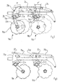
- Figure 5 shows how the disc entities 16a, 16b are turnable around the respective axles 22a, 22b (see Figs 12 , 13a and 14a ).
- the different positions of the discs 18a, 18b before and after turning are shown as solid lines and dashed lines respectively.
- the turning is executed by a hydraulic cylinder 24 simultaneously affecting a moment arm 25b arranged on beam 14b, so that it together with the disc entity 16b can turn itself around the axle 22b, and a length-adjustable linking member 26, which links together the moment arms 25a, 25b on beams 14a and 14b, so that the disc entity 16a is also caused to turn around axle 22a.
- the turning produces a turning angle ⁇ , ⁇ '.
- the vertically lowest point on discs 18a, 18b is a different one than after turning. This means in turn that both the cutting angle ⁇ , ⁇ ' and the angle of incline ⁇ , ⁇ ' are affected.
- the turning of the disc entities is thus a way to preset the tillage angles ⁇ , ⁇ , and ⁇ ', ⁇ '.
- the arms 20a, 20b are in a known way suspended on the respective beams 14a, 14b via rubber suspensions 28 to absorb turning motions.
- This type of turning motion is however not adjustable but depends on external factors, such as stones in the soil.
- every disc entity or group of disc entities can be provided with a moment arm, and be linked to a moment arm on the corresponding separately turnable or turnable in groups disc entities on the other beam 14b.
- Figure 6 shows how the adjustment of the tillage angles ⁇ , ⁇ , and ⁇ ', ⁇ ', i.e. the turning angle ⁇ , ⁇ ' for beams 14a and 14b (and thereby also the disc entities 16a, 16b) around the axle 22a, 22b can be executed separately for the respective disc entity 16a, 16b.
- the adjusting members 31a, 31b are jointedly arranged. These are provided with openings 32 in which a pin or similar can be inserted for setting the desired turning angle of the respective disc entity 16a, 16b. Since beams 14a, 14b can be turned separately from each other, this means that the turning angles ⁇ , ⁇ ' are not necessarily of the same size.
- Figure 7 shows how adjustment of the tillage angles ⁇ , ⁇ , and ⁇ ', ⁇ ' is achieved by means of a hydraulic cylinder 32a, 32b arranged via joints between the frame 30 and the respective moment arm 25a, 25b.
- Figure 8 shows how adjustment of the tillage angles ⁇ , ⁇ , and ⁇ ', ⁇ ' is achieved by means of a rigging screw 34a, 34b arranged between the frame 30 and the respective moment arm 25a, 25b of the disc entities 16a, 16b.
- Each rigging screw has by definition a threaded sleeve with a righthand thread in one end and a lefthand thread in the other. In the ends are respectively a righthand thread screw 37a and a lefthand thread screw 37b.
- Figure 9 shows how adjustment of the tillage angles ⁇ , ⁇ , and ⁇ ', ⁇ ', of the disc entities 16a, 16b is achieved by means of a pair of linked adjusting members 26a, 26b.
- the adjusting member 26a has articulated connections to the moment arms 25a and 25b, while the adjusting member 26b has articulated connections to the moment arm 25b and the frame 30.
- Figure 10 shows how adjustment of the tillage angles ⁇ , ⁇ , and ⁇ ', ⁇ ', of the respective disc entity is achieved by means of an adjusting member 26 that has articulated connections to the moment arms 25a and 25b and a rigging screw 34, that has articulated connections to the moment arm 25b and the frame 30.
- Figure 11a shows how adjustment of the tillage angles ⁇ , ⁇ and ⁇ ', ⁇ ', for the respective disc entity is achieved by means of a single adjusting member 26 that has articulated connections to the moment arms 25a and 25b.
- Figure 11b shows in a corresponding way how adjustment of the tillage angles ⁇ , ⁇ , and ⁇ ', ⁇ ' for the respective disc entity is achieved by means of a single hydraulic cylinder 32 that has articulated connections to the moment arms 25a and 25b.
- Figure 12 shows how the discs 18a, 18b interact and create furrows in the soil at relative spacings L.
- the distance to the nearest disc in the next interacting pair is denoted M.
- Figure 12 also shows the members 29a, 29b that perform the movement along the resp. beam 14a, 14b, which will be explained further below.
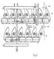
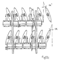
- Figures 13a - 13c show how the cutting angle ⁇ , ⁇ ' is affected for interacting discs 18a, 18b when the disc entities are turned so that the turning angle ⁇ , ⁇ ' is affected.
- the cutting angle ⁇ , ⁇ ' thus increases with increasing turning angle ⁇ , ⁇ '
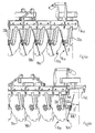
- Figures 14a - 14c show how the angle of incline ⁇ , ⁇ ' is affected for interacting discs 18a, 18b when the disc entities are turned so that the turning angle ⁇ , ⁇ ' is affected.
- the angle of incline ⁇ , ⁇ ' thus decreases with increasing turning angle ⁇ , ⁇ '.
- the spacing L between the vertically lowest point on interacting discs is also altered. This occurs without active sideways displacement of any of the beams, the sideways displacement is caused by the turning of the disc entities. Compare with what is stated above in connection with Figure 5 that the lowest point on the disc varies before and after turning.
- Figure 15 shows how compensation is made for the altered spacing L by the disc entities on one beam 14b being moved to the side by means of a member 29 for sideways displacement in the form of a hydraulic cylinder.
- the figure also shows an alternative turning axle 22a, 22b, which coincides with the extension of beam 14a, 14b (this also regards the embodiments of figures 16-18b ).
- the turning movement of beams 14a, 14b, i.e. also the disc entities 16a, 16b is achieved by a hydraulic cylinder 24 connected to moment arm 25b, which has in turn an articulated connection to moment arm 25a via linking member 26 (compare Fig. 5 above).
- the other end of the hydraulic cylinder 24 has an articulated connection to the frame 30.
- Figure 16 shows how compensation is made for the shortened spacing by the disc entities on both the beams 14a, 14b being displaced sideways by two sideways displacing members 29a, 29b in the form of hydraulic cylinders.
- Figures 17a and 17b show how the beams 14a, 14b are linked by parallel rods 40 via joints 41.
- the frame 30 is provided with a pair of joints 42, around which the parallel rods 40 are jointed, for example at the mid-point of the parallel rods.
- the hydraulic cylinder 29 (not shown in Figure 17b for the sake of clarity) affects the parallel rods 40 in such a way that they are forced to rotate around their respective joint 42, which in turn affects the displacement of the beams 14a, 14b relative to each other, so that the desired adjustment of the spacing between interacting disc entities is achieved.
- the hydraulic cylinder 24 (not shown in Figure 17b for the sake of clarity), as described above in connection with Figure 5 , executes turning of the disc entities.
- Figure 18a shows the use of a cylinder 29 for sideways displacement of the beam 14a and a cylinder 24 for turning of the beam 14b.
- Figure 18b shows instead the use of a cylinder 24 for turning of beam 14b and a cylinder 29 for sideways displacement of the same beam 14b, while beam 14a remains unaffected.
- the cylinders 24 and 29 are used for turning and sideways displacement of beam 14a, while beam 14b remains unaffected.
- Figures 19a and 19b show how beams 14a and 14b are suspended on the frame 30 via linking members 44.
- Beams 14a and 14b are also linked to each other by means of the rigging screw 29 via jointed first linking member 43.
- Adjustment of the turning angle ⁇ , ⁇ ' of the disc entities is achieved by adjusting the moment arms 25a, 25b.
- the sideways displacement, i.e. adjustment of the spacing L, is achieved by adjustment of the rigging screw 29, which together with the jointed second linking member 44 causes a displacement of beam 14a relative to beam 14b.
- the rigging screw 29 can of course by replaced by a hydraulic cylinder.
- Figures 20a and 20b show with increasing turning angle ⁇ , ⁇ ' how turning and sideways displacement are achieved with a single cylinder 24.
- the rigging screw 29, which is jointed to the frame 30 of the soil tillage entity and to beam 14b, forces sideways displacing of beam 14b while the disc entities 16a, 16b are being turned.
- Figures 21a and 21b show how turning and sideways displacement are achieved with a single hydraulic cylinder 24 in an alternative way.
- the hydraulic cylinder 24 is jointed to the frame 30 of the soil tillage entity and to beam 14b.
- the rigging screw 29 is likewise jointed to the frame 30 of the soil tillage entity and to beam 14b. During operation of the hydraulic cylinder 24, this presses beam 14b so that it is displaced sideways. At the same time, the rigging screw 29 forces beam 14b to be turned together with the disc entities 16a, 16b.
- Figures 22a and 22b show two beams at angles to each other, and provided with disc entities 16a, 16b.
- the beams are displaced sideways by means of the rigging screws 29a, 29b. Thanks to the angle that the beams have relative to each other, adjustment of the spacing L does not require as great a sideways displacement of the disc entities 16a, 16b as for parallel beams.
- Figure 23 shows how four rows of disc entities 16a, 16b are arranged behind each other.
- disc entities are turned together with their respective beam.
- the beam could be provided with disc entities that are separately turnable, or only together with the corresponding interacting disc entity on the other beam.
- the disc entities can also be turnable separately or in groups around a fixed beam.
- groups of discs on the same beam can be turnable independently of each other or together with corresponding groups on the other beam.
- two or more soil tillage entities can be placed beside each other.
- Figures 5 - 11b show different ways to turn beams 14a, 14b with disc entities 16a, 16b. Of course, any one of these can be used together with the different variants of sideways displacement shown in Figures 12 and 15 - 22b . Likewise, all the variants described above can be arranged in the constellation shown in Figure 23 .
- the hydraulic cylinders described above are of course adjustable, for example from a control panel on the agricultural implement or in a towing vehicle.
Landscapes
- Life Sciences & Earth Sciences (AREA)
- Engineering & Computer Science (AREA)
- Mechanical Engineering (AREA)
- Soil Sciences (AREA)
- Environmental Sciences (AREA)
- Soil Working Implements (AREA)
- Zoology (AREA)
- Braking Arrangements (AREA)
Abstract
Description
- The present invention relates to a soil tillage entity comprising at least two essentially horizontal beams intended to be arranged at an angle to the direction of travel during soil tillage, at least one disc entity with a disc for soil tillage arranged on the respective beam, wherein the said discs are arranged essentially behind one another in the direction of travel for interacting soil tillage, and wherein the angle of at least one of the discs relative to the direction of travel is adjustable.
- The invention also relates to agricultural machine comprising such a soil tillage entity.
- Such a soil tillage and such an agricultural machine entity are known through
EP-A-0 428 198 , which describes the adjustment of the angle of the disc relative to the direction of travel (also called cutting angle) by turning one or several disc entities around a vertical axle. This turning can be performed for one disc entity separately or several together. The soil tillage entity described is disadvantageous because it requires a large number of axles journalled in bearings. -
WO-A-00/74464 - One of the objects of the present invention is to create a soil tillage entity with improved design with respect to the adjustment of the disc entities.
- This has been achieved by a soil tillage entity of the initially defined type, wherein a a turning device is adapted to turn at least one of the disc entities, around an essentially horizontal axle for adjustment of the tillage angle of the discs, and that a displacing device is adapted to displace at least one of the disc entities essentially along the lengthwise extension of the said beam, for adjustment of the tillage position of the discs relative to one another, wherein the axle of rotation of the disc entity and the axis of rotation of its disc are not parallel. Accordingly, the angle between the axle of rotation of the disc entity and the axis of rotation of its disc is more than 0°. Hereby is achieved a less cost-demanding construction, which also has a simplified adjustment of the discs.
- The said displacement preferably occurs for at least one disc entity in one movement together with the turning. Alternatively the said displacement occurs for at least one of the said disc entities separately from the said turning. Hereby are achieved two alternative adjustment possibilities with different degrees of rationalisation.
- The turning device suitably comprises at least one turning means for execution of the turning movement. The displacing device further comprises at least one lateral displacement member for execution of the displacing movement. Hereby the turning movement and the displacing movement can be executed by means of remote control, either from the agricultural implement or from the tractor.
- At least one lateral displacement member is arranged in such a way that the said turning and the said displacing are executed in one movement. The adjustment is hereby rationalised further.
- There is preferably a turning means for execution of the turning movement and the displacing movement. Hereby, simultaneous displacing and turning can be executed by means of remote control rather than manually.
- Suitably the turning device is adapted to turn one disc entity and the displacing device is adapted to displace the other disc entity.
- Alternatively, the turning device is adapted to turn one disc entity and the displacing device is adapted to displace the same disc entity.
- Alternatively, the turning device is adapted to turn and displace both the one and the other disc entity.
- In the following, the invention is described in more detail with reference to the attached drawings in which:
-
Figure 1 is a perspective view of an agricultural machine comprising a soil tillage entity according to the invention, -
Figure 2 is a perspective view the soil tillage entity shown inFigure 1 and also definition of cutting angle and angle of incline, -
Figure 3 is a view from above of a part of the soil tillage entity shown inFigure 2 and also definition of the cutting angle, -
Figures 4a and 4b illustrate in different perspectives a part of the soil tillage entity shown inFigure 2 and also definition of angle of incline, -
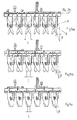
Figure 5 is a side view of the first embodiment of a pair of interacting disc entities on a soil tillage entity, -
Figure 6 illustrates a second embodiment of a pair of interacting disc entities, -
Figure 7 illustrates a third embodiment of a pair of interacting disc entities, -
Figure 8 illustrates a fourth embodiment of a pair of interacting disc entities, -
Figure 9 illustrates a fifth embodiment of a pair of interacting disc entities, -
Figure 10 illustrates a sixth embodiment of a pair of interacting disc entities, -
Figures 11a and 11b illustrate a seventh embodiment of a pair of interacting disc entities, -
Figure 12 illustrates the effect of the soil tillage entity on the soil, and also definition of tillage position, -
Figures 13a - 13c illustrate adjustment of the cutting angle, -
Figures 14a - 14c illustrate adjustment of the angle of incline, -
Figure 15 illustrates an embodiment of separate adjustment of tillage position and cutting angle, -
Figure 16 illustrates an alternative embodiment of separate adjustment of tillage position and cutting angle, -
Figures 17a - 17b illustrate an alternative embodiment of separate adjustment of tillage position and cutting angle, -
Figures 18a - 18b illustrate likewise an alternative embodiment of separate adjustment of tillage position and cutting angle, -
Figures 19a - 19b illustrate likewise an alternative embodiment of separate adjustment of tillage position and cutting angle, -
Figures 20a - 20b illustrate simultaneous adjustment of cutting angle and tillage position with a power source, -
Figures 21a - 21b show an alternative simultaneous adjustment of cutting angle and tillage position with a power source, -
Figures 22a - 22b show a soil tillage entity with angled beams, -
Figure 23 illustrates a soil tillage entity with four beams provided with disc entities. -
Figure 1 shows in perspective anagricultural machine 2 with atowing device 4 intended to be fixed to a towing vehicle, such as a tractor. Anelongated beam 6 carries support wheels 8 for transport on road, roller rings 10 and aframe 11 for asoil tillage entity 12. -
Figure 2 shows thesoil tillage entity 12 comprising a pair of essentiallyparallel beams disc entities disc arm Figure 3 ). Thediscs Figure 1 ), spherical or have other suitable form. Thebeams turning device 21a and sideways displaceable by means of adisplacing device 21b, which will be explained more fully below. - The
disc entities 16a are linked bybeam 14a and form one entity. The same applies fordisc entities 16b andbeam 14b. -
Disc 18a has a cutting angle α relative to the direction of travel (see alsoFigure 3 ) and an angle of incline β relative to the vertical plane (see alsoFigures 4a and 4b ). Thedisc 18b that is behinddisc 18a and that interacts with it has a corresponding cutting angle α' and an angle of incline β' but in the opposite direction. It should be noted that cutting angle α can of course be identical with cutting angle α', but they can equally well differ from each other by a lot or a little. The same applies for the angle of incline β, β' of the interactingdiscs - The cutting angle α, α' and the angle of incline β, β' can be combined in the expression tillage angle, which can be adjusted for adapting to the soil type to be tilled, the working depth, the presence of plants and plant residues on the surface and in the soil, the desired soil consistency after tillage, the driving speed, the fuel consumption rate, etc.
-
Figure 5 shows how thedisc entities respective axles Figs 12 ,13a and14a ). The different positions of thediscs hydraulic cylinder 24 simultaneously affecting amoment arm 25b arranged onbeam 14b, so that it together with thedisc entity 16b can turn itself around theaxle 22b, and a length-adjustable linking member 26, which links together themoment arms beams disc entity 16a is also caused to turn aroundaxle 22a. The turning produces a turning angle ϕ, ϕ'. - After turning, the vertically lowest point on
discs - The
arms respective beams rubber suspensions 28 to absorb turning motions. This type of turning motion is however not adjustable but depends on external factors, such as stones in the soil. - Partly hidden is shown a
member respective beams - In the event of the disc entities on the one
beam 14a being separately turnable, or turnable in groups, then of course every disc entity or group of disc entities can be provided with a moment arm, and be linked to a moment arm on the corresponding separately turnable or turnable in groups disc entities on theother beam 14b. -
Figure 6 shows how the adjustment of the tillage angles α, β, and α', β', i.e. the turning angle ϕ, ϕ' forbeams disc entities axle respective disc entity frame 30 of the soil tillage entity and themoment arms beams members 31a, 31b are jointedly arranged. These are provided withopenings 32 in which a pin or similar can be inserted for setting the desired turning angle of therespective disc entity beams -
Figure 7 shows how adjustment of the tillage angles α, β, and α', β' is achieved by means of ahydraulic cylinder frame 30 and therespective moment arm -
Figure 8 shows how adjustment of the tillage angles α, β, and α', β' is achieved by means of a riggingscrew frame 30 and therespective moment arm disc entities righthand thread screw 37a and alefthand thread screw 37b. -
Figure 9 shows how adjustment of the tillage angles α, β, and α', β', of thedisc entities members member 26a has articulated connections to themoment arms member 26b has articulated connections to themoment arm 25b and theframe 30. -
Figure 10 shows how adjustment of the tillage angles α, β, and α', β', of the respective disc entity is achieved by means of an adjustingmember 26 that has articulated connections to themoment arms screw 34, that has articulated connections to themoment arm 25b and theframe 30. -
Figure 11a shows how adjustment of the tillage angles α, β and α', β', for the respective disc entity is achieved by means of a single adjustingmember 26 that has articulated connections to themoment arms -
Figure 11b shows in a corresponding way how adjustment of the tillage angles α, β, and α', β' for the respective disc entity is achieved by means of a singlehydraulic cylinder 32 that has articulated connections to themoment arms -
Figure 12 shows how thediscs -
Figure 12 also shows themembers beam -
Figures 13a - 13c show how the cutting angle α, α' is affected for interactingdiscs -
Figures 14a - 14c show how the angle of incline β, β' is affected for interactingdiscs - By turning of the
disc entities Figure 5 that the lowest point on the disc varies before and after turning. - This means therefore that the cutting angle α, α' can of course be adjusted simply by turning of the disc entities, but that this will have a negative effect on the tillage result, since the sideways spacing of the discs relative to each other is affected.
-
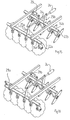
Figure 15 shows how compensation is made for the altered spacing L by the disc entities on onebeam 14b being moved to the side by means of amember 29 for sideways displacement in the form of a hydraulic cylinder. The figure also shows analternative turning axle beam figures 16-18b ). The turning movement ofbeams disc entities hydraulic cylinder 24 connected tomoment arm 25b, which has in turn an articulated connection tomoment arm 25a via linking member 26 (compareFig. 5 above). The other end of thehydraulic cylinder 24 has an articulated connection to theframe 30. -
Figure 16 shows how compensation is made for the shortened spacing by the disc entities on both thebeams sideways displacing members -
Figures 17a and 17b show how thebeams parallel rods 40 viajoints 41. Theframe 30 is provided with a pair ofjoints 42, around which theparallel rods 40 are jointed, for example at the mid-point of the parallel rods. The hydraulic cylinder 29 (not shown inFigure 17b for the sake of clarity) affects theparallel rods 40 in such a way that they are forced to rotate around their respective joint 42, which in turn affects the displacement of thebeams Figure 17b for the sake of clarity), as described above in connection withFigure 5 , executes turning of the disc entities. -
Figure 18a shows the use of acylinder 29 for sideways displacement of thebeam 14a and acylinder 24 for turning of thebeam 14b. -
Figure 18b shows instead the use of acylinder 24 for turning ofbeam 14b and acylinder 29 for sideways displacement of thesame beam 14b, whilebeam 14a remains unaffected. Alternatively thecylinders beam 14a, whilebeam 14b remains unaffected. -
Figures 19a and 19b show how beams 14a and 14b are suspended on theframe 30 via linkingmembers 44.Beams screw 29 via jointed first linking member 43. Adjustment of the turning angle ϕ, ϕ' of the disc entities is achieved by adjusting themoment arms screw 29, which together with the jointed second linkingmember 44 causes a displacement ofbeam 14a relative tobeam 14b. The riggingscrew 29 can of course by replaced by a hydraulic cylinder. -
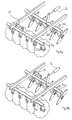
Figures 20a and 20b show with increasing turning angle ϕ, ϕ' how turning and sideways displacement are achieved with asingle cylinder 24. Hereby the riggingscrew 29, which is jointed to theframe 30 of the soil tillage entity and tobeam 14b, forces sideways displacing ofbeam 14b while thedisc entities -
Figures 21a and 21b show how turning and sideways displacement are achieved with a singlehydraulic cylinder 24 in an alternative way. Thehydraulic cylinder 24 is jointed to theframe 30 of the soil tillage entity and tobeam 14b. The riggingscrew 29 is likewise jointed to theframe 30 of the soil tillage entity and tobeam 14b. During operation of thehydraulic cylinder 24, this pressesbeam 14b so that it is displaced sideways. At the same time, the riggingscrew 29forces beam 14b to be turned together with thedisc entities -
Figures 22a and 22b show two beams at angles to each other, and provided withdisc entities beams screws disc entities -
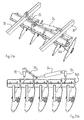
Figure 23 shows how four rows ofdisc entities - For all the above embodiments, it is a prerequisite that the angle between the axle of
rotation disc entity disc - In the embodiments exemplified above, it is only illustrated that all disc entities are turned together with their respective beam. Of course the beam could be provided with disc entities that are separately turnable, or only together with the corresponding interacting disc entity on the other beam. The disc entities can also be turnable separately or in groups around a fixed beam. Alternatively, groups of discs on the same beam can be turnable independently of each other or together with corresponding groups on the other beam. Furthermore, two or more soil tillage entities can be placed beside each other.
-
Figures 5 - 11b show different ways to turnbeams disc entities Figures 12 and15 - 22b . Likewise, all the variants described above can be arranged in the constellation shown inFigure 23 . - The hydraulic cylinders described above are of course adjustable, for example from a control panel on the agricultural implement or in a towing vehicle.
Claims (10)
- A soil tillage entity comprising at least two essentially horizontal beams (14a, 14b) intended to be arranged at an angle to the direction of travel during soil tillage, at least one disc entity (16a, 16b) with a disc (18a, 18b) for soil tillage arranged on the respective beam (14a, 14b), wherein the said discs (18a, 18b) are arranged essentially behind one another in the direction of travel for interacting soil tillage, and wherein the angle (α, α') of at least one of the discs relative to the direction of travel is adjustable, characterised in that a turning device (21a) is adapted to turn at least one of the disc entities (16a, 16b) around an essentially horizontal axle (22a, 22b) for adjustment of the tillage angle (α, β; α', β') of the discs, and that a displacing device (21b) is adapted to displace at least one of the disc entities (16a, 16b) essentially along the lengthwise extension of the said beam (14a, 14b), for adjustment of the tillage position (L) of the discs relative to one another, wherein the axle of rotation (22a, 22b) of the disc entity (16a, 16b) and the axis of rotation (A) of its disc (18a, 18b) are not parallel.
- A soil tillage entity according to Claim 1, wherein the said displacement for at least one of the disc entities (16a, 16b) occurs in one movement together with the turning.
- A soil tillage entity according to Claim 1, wherein the said displacement for at least one of the said disc entities (16a, 16b) occurs separately from the said turning.
- A soil tillage entity according to any one of the preceding claims, wherein the turning device (21a) comprises at least one turning means (24) for execution of the turning movement, and that the displacing device (21b) comprises at least one lateral displacement member (29; 29a; 29b) for execution of the displacing movement.
- A soil tillage entity according to Claim 1, wherein one lateral displacement member (29) is arranged in such a way that the said turning and the said displacing are executed in one movement.
- A soil tillage entity according to Claim 5, comprising a turning means (24) for execution of the turning movement and the displacing movement.
- A soil tillage entity according to any one of the preceding claims, wherein the turning device (21a) is adapted to turn one disc entity (16a) and that the displacing device (21b) is adapted to displace the other disc entity (16b).
- A soil tillage entity according to any one of Claims 1 - 6, wherein the turning device (21a) is adapted to turn one disc entity (16a) and that the displacing device (21b) is adapted to displace the same disc entity (16a).
- A soil tillage entity according to any one of Claims 1 - 6, wherein the turning device (21a) is adapted to turn and displace both the one and the other disc entity (16a, 16b).
- An agricultural machine comprising at least one soil tillage entity according to any one of the preceding claims.
Applications Claiming Priority (3)
| Application Number | Priority Date | Filing Date | Title |
|---|---|---|---|
| SE0202129 | 2002-07-05 | ||
| SE0202129A SE523809E (en) | 2002-07-05 | 2002-07-05 | A tillage unit with angled plates |
| PCT/SE2003/001149 WO2004004437A1 (en) | 2002-07-05 | 2003-07-02 | A soil tillage entity with angled discs |
Publications (2)
| Publication Number | Publication Date |
|---|---|
| EP1569506A1 EP1569506A1 (en) | 2005-09-07 |
| EP1569506B1 true EP1569506B1 (en) | 2008-03-05 |
Family
ID=20288466
Family Applications (1)
| Application Number | Title | Priority Date | Filing Date |
|---|---|---|---|
| EP03762950A Revoked EP1569506B1 (en) | 2002-07-05 | 2003-07-02 | A soil tillage entity with angled discs |
Country Status (6)
| Country | Link |
|---|---|
| EP (1) | EP1569506B1 (en) |
| AT (1) | ATE387840T1 (en) |
| AU (1) | AU2003243115A1 (en) |
| DE (1) | DE60319573T2 (en) |
| SE (1) | SE523809E (en) |
| WO (1) | WO2004004437A1 (en) |
Cited By (2)
| Publication number | Priority date | Publication date | Assignee | Title |
|---|---|---|---|---|
| DE102015116433A1 (en) | 2015-09-29 | 2017-03-30 | Amazonen-Werke H. Dreyer Gmbh & Co. Kg | Harrow |
| WO2025252790A1 (en) * | 2024-06-05 | 2025-12-11 | Evagro Concept | Soil-working machine |
Families Citing this family (13)
| Publication number | Priority date | Publication date | Assignee | Title |
|---|---|---|---|---|
| DE10336652A1 (en) * | 2003-08-09 | 2005-02-24 | Amazonen-Werke H. Dreyer Gmbh & Co. Kg | disk device |
| FR2865102B1 (en) * | 2004-01-19 | 2006-04-07 | Michel Evin | SOIL WORKING MACHINE, TYPE DECHAUMEUSE |
| FR2867943B1 (en) * | 2004-03-24 | 2007-08-31 | Michel Evin | SOIL WORKING DISC AND SOIL TREATMENT MACHINE EQUIPPED WITH SUCH DISKS |
| FR2896375B1 (en) † | 2006-01-24 | 2010-03-19 | Michel Evin | SOIL WORKING MACHINE, SUCH AS DECHAUMEUSE |
| SE530920C2 (en) * | 2006-09-12 | 2008-10-21 | Vaederstad Verken Ab | agricultural Machinery |
| AR093276A1 (en) | 2011-06-03 | 2015-05-27 | Prec Planting Llc | METHODS, SYSTEMS AND APPLIANCES FOR APPLICATION SEED UNITS IN AGRICULTURE |
| WO2013049951A1 (en) * | 2011-10-04 | 2013-04-11 | Masihy Musalem Daniel | Rotary blade, clod-crusher harrow |
| DE102014109504A1 (en) * | 2014-07-08 | 2016-01-14 | Amazonen-Werke H. Dreyer Gmbh & Co. Kg | Tillage device |
| FR3063865B1 (en) * | 2017-03-17 | 2020-07-17 | Kuhn-Huard S.A. | AGRICULTURAL MACHINE FOR PREPARING THE SOIL COMPRISING TWO MUTUALLY OFFSET DISC TRAINS ADJUSTABLE IN THE DIRECTION IN ADVANCE |
| DE102017119971B4 (en) * | 2017-08-31 | 2025-06-12 | Amazonen-Werke H. Dreyer SE & Co. KG | Soil cultivation equipment |
| CZ308835B6 (en) * | 2017-11-10 | 2021-06-30 | Farmet A.S. | Countersinking adjustment equipment and agricultural processing machine |
| IT201900007226A1 (en) * | 2019-05-24 | 2020-11-24 | Mauro Collovati | AGRICULTURAL MACHINE FOR TREATMENT OF GRASS COTIC AND RELATIVE VEGETABLE MASS |
| DE102021119841A1 (en) | 2021-07-30 | 2023-02-02 | Treffler Maschinenbau Gmbh & Co. Kg | Working element for tillage |
Family Cites Families (2)
| Publication number | Priority date | Publication date | Assignee | Title |
|---|---|---|---|---|
| US3675725A (en) * | 1970-05-27 | 1972-07-11 | Henry F Schultz | Disc implement |
| SE520059C2 (en) * | 1999-06-08 | 2003-05-13 | Vaederstad Verken Ab | Disc harrows |
-
2002
- 2002-07-05 SE SE0202129A patent/SE523809E/en not_active IP Right Cessation
-
2003
- 2003-07-02 AT AT03762950T patent/ATE387840T1/en not_active IP Right Cessation
- 2003-07-02 WO PCT/SE2003/001149 patent/WO2004004437A1/en not_active Ceased
- 2003-07-02 AU AU2003243115A patent/AU2003243115A1/en not_active Abandoned
- 2003-07-02 EP EP03762950A patent/EP1569506B1/en not_active Revoked
- 2003-07-02 DE DE60319573T patent/DE60319573T2/en not_active Expired - Lifetime
Cited By (4)
| Publication number | Priority date | Publication date | Assignee | Title |
|---|---|---|---|---|
| DE102015116433A1 (en) | 2015-09-29 | 2017-03-30 | Amazonen-Werke H. Dreyer Gmbh & Co. Kg | Harrow |
| EP3152990A1 (en) | 2015-09-29 | 2017-04-12 | Amazonen-Werke H. Dreyer GmbH & Co. KG | Soil cultivation device |
| WO2025252790A1 (en) * | 2024-06-05 | 2025-12-11 | Evagro Concept | Soil-working machine |
| FR3162964A1 (en) * | 2024-06-05 | 2025-12-12 | Evagro Concept | Soil cultivation machine |
Also Published As
| Publication number | Publication date |
|---|---|
| ATE387840T1 (en) | 2008-03-15 |
| EP1569506A1 (en) | 2005-09-07 |
| SE523809C2 (en) | 2004-05-18 |
| DE60319573D1 (en) | 2008-04-17 |
| WO2004004437A1 (en) | 2004-01-15 |
| AU2003243115A1 (en) | 2004-01-23 |
| DE60319573T2 (en) | 2009-03-19 |
| SE523809E (en) | 2006-04-25 |
| SE0202129D0 (en) | 2002-07-05 |
| SE0202129L (en) | 2004-01-06 |
Similar Documents
| Publication | Publication Date | Title |
|---|---|---|
| EP1569506A1 (en) | A soil tillage entity with angled discs | |
| US9253937B2 (en) | Towed agricultural machine with packer unit and method for operating such a machine | |
| RU2472329C2 (en) | Hinge mechanism for working machine | |
| CN211831759U (en) | Soil preparation machine | |
| US20190159395A1 (en) | Angle adjustable coulter wheel assembly | |
| US10499552B2 (en) | Tillage implement with preset disk frame angle | |
| CN1909776A (en) | Disc harrow type soil tillage machine | |
| WO2013036191A1 (en) | Agricultural implement having height adjustment and method of adjusting height of agricultural implement | |
| DK2793544T3 (en) | Agricultural machine with improved ground following for working members | |
| WO2004004438A1 (en) | Soil preparation unit | |
| CN105144867A (en) | Disc plough | |
| US12295275B2 (en) | Agricultural implement and method of controlling agricultural implement | |
| US11785871B2 (en) | Adjustable cultivator apparatus, systems, and methods | |
| CN202799618U (en) | Earth covering device | |
| CN205052072U (en) | Coulter assembly for disk plough | |
| CN205040156U (en) | Disc plough | |
| RU99270U1 (en) | DISK HARROW FOR TILLING SOIL IN PERENNIAL PLANTS | |
| DE102010013470B4 (en) | Device for distributing seed and / or fertilizer | |
| CN104756633B (en) | Deep scarification vibration plough | |
| CN220476249U (en) | Turnover plow | |
| RU2374804C1 (en) | Soil-cultivating wide-cut implement | |
| CN222885107U (en) | Agricultural rooter | |
| KR20150116201A (en) | Forming apparatus of a ridge between fields for tractor | |
| CN105210476A (en) | Disk plow colter assembly | |
| DE10104911A1 (en) | Soil cultivating machine comprises rows of hollow disks rotating about vertical axes at a working angle adjustable about an ideal center of rotation located in the region of the lower third on the imaginary disk surface |
Legal Events
| Date | Code | Title | Description |
|---|---|---|---|
| PUAI | Public reference made under article 153(3) epc to a published international application that has entered the european phase |
Free format text: ORIGINAL CODE: 0009012 |
|
| 17P | Request for examination filed |
Effective date: 20041208 |
|
| AK | Designated contracting states |
Kind code of ref document: A1 Designated state(s): AT BE BG CH CY CZ DE DK EE ES FI FR GB GR HU IE IT LI LU MC NL PT RO SE SI SK TR |
|
| AX | Request for extension of the european patent |
Extension state: AL LT LV MK |
|
| DAX | Request for extension of the european patent (deleted) | ||
| 17Q | First examination report despatched |
Effective date: 20061218 |
|
| GRAP | Despatch of communication of intention to grant a patent |
Free format text: ORIGINAL CODE: EPIDOSNIGR1 |
|
| GRAS | Grant fee paid |
Free format text: ORIGINAL CODE: EPIDOSNIGR3 |
|
| GRAA | (expected) grant |
Free format text: ORIGINAL CODE: 0009210 |
|
| AK | Designated contracting states |
Kind code of ref document: B1 Designated state(s): AT BE BG CH CY CZ DE DK EE ES FI FR GB GR HU IE IT LI LU MC NL PT RO SE SI SK TR |
|
| REG | Reference to a national code |
Ref country code: GB Ref legal event code: FG4D |
|
| REG | Reference to a national code |
Ref country code: CH Ref legal event code: EP |
|
| REG | Reference to a national code |
Ref country code: IE Ref legal event code: FG4D |
|
| REF | Corresponds to: |
Ref document number: 60319573 Country of ref document: DE Date of ref document: 20080417 Kind code of ref document: P |
|
| PG25 | Lapsed in a contracting state [announced via postgrant information from national office to epo] |
Ref country code: FI Free format text: LAPSE BECAUSE OF FAILURE TO SUBMIT A TRANSLATION OF THE DESCRIPTION OR TO PAY THE FEE WITHIN THE PRESCRIBED TIME-LIMIT Effective date: 20080305 Ref country code: ES Free format text: LAPSE BECAUSE OF FAILURE TO SUBMIT A TRANSLATION OF THE DESCRIPTION OR TO PAY THE FEE WITHIN THE PRESCRIBED TIME-LIMIT Effective date: 20080616 |
|
| PG25 | Lapsed in a contracting state [announced via postgrant information from national office to epo] |
Ref country code: AT Free format text: LAPSE BECAUSE OF FAILURE TO SUBMIT A TRANSLATION OF THE DESCRIPTION OR TO PAY THE FEE WITHIN THE PRESCRIBED TIME-LIMIT Effective date: 20080305 |
|
| NLV1 | Nl: lapsed or annulled due to failure to fulfill the requirements of art. 29p and 29m of the patents act | ||
| PG25 | Lapsed in a contracting state [announced via postgrant information from national office to epo] |
Ref country code: SI Free format text: LAPSE BECAUSE OF FAILURE TO SUBMIT A TRANSLATION OF THE DESCRIPTION OR TO PAY THE FEE WITHIN THE PRESCRIBED TIME-LIMIT Effective date: 20080305 Ref country code: BE Free format text: LAPSE BECAUSE OF FAILURE TO SUBMIT A TRANSLATION OF THE DESCRIPTION OR TO PAY THE FEE WITHIN THE PRESCRIBED TIME-LIMIT Effective date: 20080305 |
|
| ET | Fr: translation filed | ||
| PG25 | Lapsed in a contracting state [announced via postgrant information from national office to epo] |
Ref country code: PT Free format text: LAPSE BECAUSE OF FAILURE TO SUBMIT A TRANSLATION OF THE DESCRIPTION OR TO PAY THE FEE WITHIN THE PRESCRIBED TIME-LIMIT Effective date: 20080805 Ref country code: NL Free format text: LAPSE BECAUSE OF FAILURE TO SUBMIT A TRANSLATION OF THE DESCRIPTION OR TO PAY THE FEE WITHIN THE PRESCRIBED TIME-LIMIT Effective date: 20080305 Ref country code: SE Free format text: LAPSE BECAUSE OF FAILURE TO SUBMIT A TRANSLATION OF THE DESCRIPTION OR TO PAY THE FEE WITHIN THE PRESCRIBED TIME-LIMIT Effective date: 20080605 Ref country code: CZ Free format text: LAPSE BECAUSE OF FAILURE TO SUBMIT A TRANSLATION OF THE DESCRIPTION OR TO PAY THE FEE WITHIN THE PRESCRIBED TIME-LIMIT Effective date: 20080305 Ref country code: SK Free format text: LAPSE BECAUSE OF FAILURE TO SUBMIT A TRANSLATION OF THE DESCRIPTION OR TO PAY THE FEE WITHIN THE PRESCRIBED TIME-LIMIT Effective date: 20080305 |
|
| PG25 | Lapsed in a contracting state [announced via postgrant information from national office to epo] |
Ref country code: RO Free format text: LAPSE BECAUSE OF FAILURE TO SUBMIT A TRANSLATION OF THE DESCRIPTION OR TO PAY THE FEE WITHIN THE PRESCRIBED TIME-LIMIT Effective date: 20080305 |
|
| PLBI | Opposition filed |
Free format text: ORIGINAL CODE: 0009260 |
|
| 26 | Opposition filed |
Opponent name: AMAZONEN-WERKE H. DREYER GMBH & CO. KG Effective date: 20081202 |
|
| PLAX | Notice of opposition and request to file observation + time limit sent |
Free format text: ORIGINAL CODE: EPIDOSNOBS2 |
|
| PG25 | Lapsed in a contracting state [announced via postgrant information from national office to epo] |
Ref country code: DK Free format text: LAPSE BECAUSE OF FAILURE TO SUBMIT A TRANSLATION OF THE DESCRIPTION OR TO PAY THE FEE WITHIN THE PRESCRIBED TIME-LIMIT Effective date: 20080305 |
|
| REG | Reference to a national code |
Ref country code: CH Ref legal event code: PL |
|
| PG25 | Lapsed in a contracting state [announced via postgrant information from national office to epo] |
Ref country code: MC Free format text: LAPSE BECAUSE OF NON-PAYMENT OF DUE FEES Effective date: 20080731 |
|
| PG25 | Lapsed in a contracting state [announced via postgrant information from national office to epo] |
Ref country code: EE Free format text: LAPSE BECAUSE OF FAILURE TO SUBMIT A TRANSLATION OF THE DESCRIPTION OR TO PAY THE FEE WITHIN THE PRESCRIBED TIME-LIMIT Effective date: 20080305 Ref country code: BG Free format text: LAPSE BECAUSE OF FAILURE TO SUBMIT A TRANSLATION OF THE DESCRIPTION OR TO PAY THE FEE WITHIN THE PRESCRIBED TIME-LIMIT Effective date: 20080605 |
|
| PLAF | Information modified related to communication of a notice of opposition and request to file observations + time limit |
Free format text: ORIGINAL CODE: EPIDOSCOBS2 |
|
| PG25 | Lapsed in a contracting state [announced via postgrant information from national office to epo] |
Ref country code: LI Free format text: LAPSE BECAUSE OF NON-PAYMENT OF DUE FEES Effective date: 20080731 Ref country code: CH Free format text: LAPSE BECAUSE OF NON-PAYMENT OF DUE FEES Effective date: 20080731 |
|
| PLBB | Reply of patent proprietor to notice(s) of opposition received |
Free format text: ORIGINAL CODE: EPIDOSNOBS3 |
|
| PG25 | Lapsed in a contracting state [announced via postgrant information from national office to epo] |
Ref country code: IE Free format text: LAPSE BECAUSE OF NON-PAYMENT OF DUE FEES Effective date: 20080702 |
|
| PG25 | Lapsed in a contracting state [announced via postgrant information from national office to epo] |
Ref country code: IT Free format text: LAPSE BECAUSE OF FAILURE TO SUBMIT A TRANSLATION OF THE DESCRIPTION OR TO PAY THE FEE WITHIN THE PRESCRIBED TIME-LIMIT Effective date: 20080305 |
|
| PG25 | Lapsed in a contracting state [announced via postgrant information from national office to epo] |
Ref country code: CY Free format text: LAPSE BECAUSE OF FAILURE TO SUBMIT A TRANSLATION OF THE DESCRIPTION OR TO PAY THE FEE WITHIN THE PRESCRIBED TIME-LIMIT Effective date: 20080305 |
|
| PLAB | Opposition data, opponent's data or that of the opponent's representative modified |
Free format text: ORIGINAL CODE: 0009299OPPO |
|
| R26 | Opposition filed (corrected) |
Opponent name: AMAZONEN-WERKE H. DREYER GMBH & CO. KG Effective date: 20081202 |
|
| PG25 | Lapsed in a contracting state [announced via postgrant information from national office to epo] |
Ref country code: LU Free format text: LAPSE BECAUSE OF NON-PAYMENT OF DUE FEES Effective date: 20080702 Ref country code: HU Free format text: LAPSE BECAUSE OF FAILURE TO SUBMIT A TRANSLATION OF THE DESCRIPTION OR TO PAY THE FEE WITHIN THE PRESCRIBED TIME-LIMIT Effective date: 20080906 |
|
| PG25 | Lapsed in a contracting state [announced via postgrant information from national office to epo] |
Ref country code: TR Free format text: LAPSE BECAUSE OF FAILURE TO SUBMIT A TRANSLATION OF THE DESCRIPTION OR TO PAY THE FEE WITHIN THE PRESCRIBED TIME-LIMIT Effective date: 20080305 |
|
| PG25 | Lapsed in a contracting state [announced via postgrant information from national office to epo] |
Ref country code: GR Free format text: LAPSE BECAUSE OF FAILURE TO SUBMIT A TRANSLATION OF THE DESCRIPTION OR TO PAY THE FEE WITHIN THE PRESCRIBED TIME-LIMIT Effective date: 20080606 |
|
| PGFP | Annual fee paid to national office [announced via postgrant information from national office to epo] |
Ref country code: DE Payment date: 20100727 Year of fee payment: 8 Ref country code: FR Payment date: 20100823 Year of fee payment: 8 |
|
| REG | Reference to a national code |
Ref country code: DE Ref legal event code: R103 Ref document number: 60319573 Country of ref document: DE Ref country code: DE Ref legal event code: R064 Ref document number: 60319573 Country of ref document: DE |
|
| RDAF | Communication despatched that patent is revoked |
Free format text: ORIGINAL CODE: EPIDOSNREV1 |
|
| RDAG | Patent revoked |
Free format text: ORIGINAL CODE: 0009271 |
|
| STAA | Information on the status of an ep patent application or granted ep patent |
Free format text: STATUS: PATENT REVOKED |
|
| 27W | Patent revoked |
Effective date: 20110315 |
|
| GBPR | Gb: patent revoked under art. 102 of the ep convention designating the uk as contracting state |
Effective date: 20110315 |
|
| REG | Reference to a national code |
Ref country code: DE Ref legal event code: R107 Ref document number: 60319573 Country of ref document: DE Effective date: 20111013 |
|
| PGFP | Annual fee paid to national office [announced via postgrant information from national office to epo] |
Ref country code: GB Payment date: 20110727 Year of fee payment: 9 |