EP1569460B1 - Motion compensation method, image encoding method, and image decoding method - Google Patents
Motion compensation method, image encoding method, and image decoding method Download PDFInfo
- Publication number
- EP1569460B1 EP1569460B1 EP03811870.9A EP03811870A EP1569460B1 EP 1569460 B1 EP1569460 B1 EP 1569460B1 EP 03811870 A EP03811870 A EP 03811870A EP 1569460 B1 EP1569460 B1 EP 1569460B1
- Authority
- EP
- European Patent Office
- Prior art keywords
- motion
- picture
- block
- motion vector
- compensated
- Prior art date
- Legal status (The legal status is an assumption and is not a legal conclusion. Google has not performed a legal analysis and makes no representation as to the accuracy of the status listed.)
- Expired - Lifetime
Links
- 230000033001 locomotion Effects 0.000 title claims description 540
- 238000000034 method Methods 0.000 title claims description 115
- 239000013598 vector Substances 0.000 claims description 289
- 238000006243 chemical reaction Methods 0.000 description 44
- 238000010586 diagram Methods 0.000 description 28
- 238000004891 communication Methods 0.000 description 11
- 230000000694 effects Effects 0.000 description 8
- 238000001228 spectrum Methods 0.000 description 6
- 238000013139 quantization Methods 0.000 description 4
- 238000004364 calculation method Methods 0.000 description 3
- 238000005516 engineering process Methods 0.000 description 3
- 230000006870 function Effects 0.000 description 3
- 230000002123 temporal effect Effects 0.000 description 3
- 230000005540 biological transmission Effects 0.000 description 2
- 230000006835 compression Effects 0.000 description 2
- 238000007906 compression Methods 0.000 description 2
- 239000000284 extract Substances 0.000 description 2
- 239000004973 liquid crystal related substance Substances 0.000 description 2
- 230000003287 optical effect Effects 0.000 description 2
- 230000001360 synchronised effect Effects 0.000 description 2
- 230000000007 visual effect Effects 0.000 description 2
- 230000007423 decrease Effects 0.000 description 1
- 238000001914 filtration Methods 0.000 description 1
- 238000010295 mobile communication Methods 0.000 description 1
- 230000008520 organization Effects 0.000 description 1
- 238000005192 partition Methods 0.000 description 1
- 230000000750 progressive effect Effects 0.000 description 1
- 230000005236 sound signal Effects 0.000 description 1
- 230000008685 targeting Effects 0.000 description 1
Images


Classifications
-
- H—ELECTRICITY
- H04—ELECTRIC COMMUNICATION TECHNIQUE
- H04N—PICTORIAL COMMUNICATION, e.g. TELEVISION
- H04N19/00—Methods or arrangements for coding, decoding, compressing or decompressing digital video signals
- H04N19/50—Methods or arrangements for coding, decoding, compressing or decompressing digital video signals using predictive coding
- H04N19/503—Methods or arrangements for coding, decoding, compressing or decompressing digital video signals using predictive coding involving temporal prediction
- H04N19/51—Motion estimation or motion compensation
- H04N19/513—Processing of motion vectors
-
- H—ELECTRICITY
- H04—ELECTRIC COMMUNICATION TECHNIQUE
- H04N—PICTORIAL COMMUNICATION, e.g. TELEVISION
- H04N19/00—Methods or arrangements for coding, decoding, compressing or decompressing digital video signals
- H04N19/10—Methods or arrangements for coding, decoding, compressing or decompressing digital video signals using adaptive coding
- H04N19/102—Methods or arrangements for coding, decoding, compressing or decompressing digital video signals using adaptive coding characterised by the element, parameter or selection affected or controlled by the adaptive coding
- H04N19/12—Selection from among a plurality of transforms or standards, e.g. selection between discrete cosine transform [DCT] and sub-band transform or selection between H.263 and H.264
- H04N19/122—Selection of transform size, e.g. 8x8 or 2x4x8 DCT; Selection of sub-band transforms of varying structure or type
-
- H—ELECTRICITY
- H04—ELECTRIC COMMUNICATION TECHNIQUE
- H04N—PICTORIAL COMMUNICATION, e.g. TELEVISION
- H04N19/00—Methods or arrangements for coding, decoding, compressing or decompressing digital video signals
- H04N19/10—Methods or arrangements for coding, decoding, compressing or decompressing digital video signals using adaptive coding
- H04N19/134—Methods or arrangements for coding, decoding, compressing or decompressing digital video signals using adaptive coding characterised by the element, parameter or criterion affecting or controlling the adaptive coding
- H04N19/136—Incoming video signal characteristics or properties
- H04N19/137—Motion inside a coding unit, e.g. average field, frame or block difference
- H04N19/139—Analysis of motion vectors, e.g. their magnitude, direction, variance or reliability
-
- H—ELECTRICITY
- H04—ELECTRIC COMMUNICATION TECHNIQUE
- H04N—PICTORIAL COMMUNICATION, e.g. TELEVISION
- H04N19/00—Methods or arrangements for coding, decoding, compressing or decompressing digital video signals
- H04N19/10—Methods or arrangements for coding, decoding, compressing or decompressing digital video signals using adaptive coding
- H04N19/169—Methods or arrangements for coding, decoding, compressing or decompressing digital video signals using adaptive coding characterised by the coding unit, i.e. the structural portion or semantic portion of the video signal being the object or the subject of the adaptive coding
- H04N19/17—Methods or arrangements for coding, decoding, compressing or decompressing digital video signals using adaptive coding characterised by the coding unit, i.e. the structural portion or semantic portion of the video signal being the object or the subject of the adaptive coding the unit being an image region, e.g. an object
- H04N19/172—Methods or arrangements for coding, decoding, compressing or decompressing digital video signals using adaptive coding characterised by the coding unit, i.e. the structural portion or semantic portion of the video signal being the object or the subject of the adaptive coding the unit being an image region, e.g. an object the region being a picture, frame or field
-
- H—ELECTRICITY
- H04—ELECTRIC COMMUNICATION TECHNIQUE
- H04N—PICTORIAL COMMUNICATION, e.g. TELEVISION
- H04N19/00—Methods or arrangements for coding, decoding, compressing or decompressing digital video signals
- H04N19/10—Methods or arrangements for coding, decoding, compressing or decompressing digital video signals using adaptive coding
- H04N19/169—Methods or arrangements for coding, decoding, compressing or decompressing digital video signals using adaptive coding characterised by the coding unit, i.e. the structural portion or semantic portion of the video signal being the object or the subject of the adaptive coding
- H04N19/17—Methods or arrangements for coding, decoding, compressing or decompressing digital video signals using adaptive coding characterised by the coding unit, i.e. the structural portion or semantic portion of the video signal being the object or the subject of the adaptive coding the unit being an image region, e.g. an object
- H04N19/176—Methods or arrangements for coding, decoding, compressing or decompressing digital video signals using adaptive coding characterised by the coding unit, i.e. the structural portion or semantic portion of the video signal being the object or the subject of the adaptive coding the unit being an image region, e.g. an object the region being a block, e.g. a macroblock
-
- H—ELECTRICITY
- H04—ELECTRIC COMMUNICATION TECHNIQUE
- H04N—PICTORIAL COMMUNICATION, e.g. TELEVISION
- H04N19/00—Methods or arrangements for coding, decoding, compressing or decompressing digital video signals
- H04N19/50—Methods or arrangements for coding, decoding, compressing or decompressing digital video signals using predictive coding
- H04N19/503—Methods or arrangements for coding, decoding, compressing or decompressing digital video signals using predictive coding involving temporal prediction
- H04N19/51—Motion estimation or motion compensation
- H04N19/513—Processing of motion vectors
- H04N19/517—Processing of motion vectors by encoding
- H04N19/52—Processing of motion vectors by encoding by predictive encoding
-
- H—ELECTRICITY
- H04—ELECTRIC COMMUNICATION TECHNIQUE
- H04N—PICTORIAL COMMUNICATION, e.g. TELEVISION
- H04N19/00—Methods or arrangements for coding, decoding, compressing or decompressing digital video signals
- H04N19/50—Methods or arrangements for coding, decoding, compressing or decompressing digital video signals using predictive coding
- H04N19/503—Methods or arrangements for coding, decoding, compressing or decompressing digital video signals using predictive coding involving temporal prediction
- H04N19/51—Motion estimation or motion compensation
- H04N19/513—Processing of motion vectors
- H04N19/521—Processing of motion vectors for estimating the reliability of the determined motion vectors or motion vector field, e.g. for smoothing the motion vector field or for correcting motion vectors
-
- H—ELECTRICITY
- H04—ELECTRIC COMMUNICATION TECHNIQUE
- H04N—PICTORIAL COMMUNICATION, e.g. TELEVISION
- H04N19/00—Methods or arrangements for coding, decoding, compressing or decompressing digital video signals
- H04N19/50—Methods or arrangements for coding, decoding, compressing or decompressing digital video signals using predictive coding
- H04N19/503—Methods or arrangements for coding, decoding, compressing or decompressing digital video signals using predictive coding involving temporal prediction
- H04N19/51—Motion estimation or motion compensation
- H04N19/557—Motion estimation characterised by stopping computation or iteration based on certain criteria, e.g. error magnitude being too large or early exit
-
- H—ELECTRICITY
- H04—ELECTRIC COMMUNICATION TECHNIQUE
- H04N—PICTORIAL COMMUNICATION, e.g. TELEVISION
- H04N19/00—Methods or arrangements for coding, decoding, compressing or decompressing digital video signals
- H04N19/50—Methods or arrangements for coding, decoding, compressing or decompressing digital video signals using predictive coding
- H04N19/503—Methods or arrangements for coding, decoding, compressing or decompressing digital video signals using predictive coding involving temporal prediction
- H04N19/51—Motion estimation or motion compensation
- H04N19/56—Motion estimation with initialisation of the vector search, e.g. estimating a good candidate to initiate a search
-
- H—ELECTRICITY
- H04—ELECTRIC COMMUNICATION TECHNIQUE
- H04N—PICTORIAL COMMUNICATION, e.g. TELEVISION
- H04N19/00—Methods or arrangements for coding, decoding, compressing or decompressing digital video signals
- H04N19/50—Methods or arrangements for coding, decoding, compressing or decompressing digital video signals using predictive coding
- H04N19/503—Methods or arrangements for coding, decoding, compressing or decompressing digital video signals using predictive coding involving temporal prediction
- H04N19/51—Motion estimation or motion compensation
- H04N19/57—Motion estimation characterised by a search window with variable size or shape
-
- H—ELECTRICITY
- H04—ELECTRIC COMMUNICATION TECHNIQUE
- H04N—PICTORIAL COMMUNICATION, e.g. TELEVISION
- H04N19/00—Methods or arrangements for coding, decoding, compressing or decompressing digital video signals
- H04N19/50—Methods or arrangements for coding, decoding, compressing or decompressing digital video signals using predictive coding
- H04N19/503—Methods or arrangements for coding, decoding, compressing or decompressing digital video signals using predictive coding involving temporal prediction
- H04N19/51—Motion estimation or motion compensation
- H04N19/577—Motion compensation with bidirectional frame interpolation, i.e. using B-pictures
-
- H—ELECTRICITY
- H04—ELECTRIC COMMUNICATION TECHNIQUE
- H04N—PICTORIAL COMMUNICATION, e.g. TELEVISION
- H04N19/00—Methods or arrangements for coding, decoding, compressing or decompressing digital video signals
- H04N19/50—Methods or arrangements for coding, decoding, compressing or decompressing digital video signals using predictive coding
- H04N19/503—Methods or arrangements for coding, decoding, compressing or decompressing digital video signals using predictive coding involving temporal prediction
- H04N19/51—Motion estimation or motion compensation
- H04N19/583—Motion compensation with overlapping blocks
-
- H—ELECTRICITY
- H04—ELECTRIC COMMUNICATION TECHNIQUE
- H04N—PICTORIAL COMMUNICATION, e.g. TELEVISION
- H04N19/00—Methods or arrangements for coding, decoding, compressing or decompressing digital video signals
- H04N19/50—Methods or arrangements for coding, decoding, compressing or decompressing digital video signals using predictive coding
- H04N19/593—Methods or arrangements for coding, decoding, compressing or decompressing digital video signals using predictive coding involving spatial prediction techniques
-
- H—ELECTRICITY
- H04—ELECTRIC COMMUNICATION TECHNIQUE
- H04N—PICTORIAL COMMUNICATION, e.g. TELEVISION
- H04N19/00—Methods or arrangements for coding, decoding, compressing or decompressing digital video signals
- H04N19/60—Methods or arrangements for coding, decoding, compressing or decompressing digital video signals using transform coding
- H04N19/61—Methods or arrangements for coding, decoding, compressing or decompressing digital video signals using transform coding in combination with predictive coding
Definitions
- the present invention relates to a motion compensation method using motion vectors and picture coding and decoding methods using the motion compensation method.
- a picture is a term to represent one screen; it means a frame in a progressive picture and a frame or a field in an interlace picture.
- an interlace picture is a picture in which one frame is formed with two fields with different time. In coding and decoding process of an interlace picture, it is possible to process one frame as a frame "as is" or two fields. Also it is possible to process one frame structure or one field structure for each block in the frame.
- a picture that does not have a reference picture and in which intra picture prediction coding is performed is called an I picture. Additionally, a picture in which only one picture is referred and inter picture prediction coding is performed is called a P picture. Moreover, a picture in which two pictures are referred at the one time and inter picture coding can be performed is called a B picture. In a B picture, two pictures can be referred as an arbitrary combination from forward pictures or backward pictures in display order. It is possible to select appropriate reference pictures for each block that is a basic unit for coding and decoding. Two reference pictures are distinguished: a reference picture that is described earlier in a coded bit stream is the first reference picture and a reference picture that is described later in the coded bit stream is the second reference picture. But it is necessary that the reference pictures are already coded or decoded as a condition in the case of coding and decoding these pictures.
- inter picture prediction coding using motion compensation is a coding method in which motion compensation is applied to inter picture prediction.
- Motion compensation is a method that does not simply perform prediction based on pixel values of a block in a reference frame co-located with a current block but estimates motion amount (hereinafter, this is called a "motion vector".) of each part and performs prediction considering said motion amount to improve predictive accuracy and reduce data amount.
- estimating a motion vector of a current picture to be coded obtaining a predictive value that has been shifted by the amount of the motion vector and coding predictive residual that is the difference between the predictive value and a pixel value of each pixel in the current picture to be coded, successfully reduce the data amount.
- information of a motion vector is necessary at the time of decoding and therefore the motion vector is also coded and recorded or transmitted.
- the motion vector is estimated on a block-by-block basis, the blocks having a predetermined size. Concretely, the motion vector is estimated by moving each block in a reference picture corresponding to each block in a current picture to be coded in a search area and by detecting the location of the reference block that is most similar to the current block to be coded.
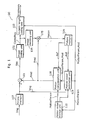
- Fig. 1 is a block diagram showing the structure of a conventional picture coding apparatus 100.
- the picture coding apparatus 100 includes a difference unit 101, an image coding unit 102, a variable length coding unit 103, an image decoding unit 104, an addition unit 105, a picture memory 106, a picture memory 107, a motion compensation unit 108, a motion vector estimation unit 109 and a motion vector storage unit 110.
- an appropriate size is selected on a macroblock-by-macroblock basis from seven block sizes and used for coding and decoding, the seven block sizes being 4 ⁇ 4 pixels, 4 ⁇ 8 pixels, 8 ⁇ 4 pixels, 8 ⁇ 8 pixels, 8 ⁇ 16 pixels, 16 ⁇ 8 pixels and 16 ⁇ 16 pixels according to ITU-T H.26L TML8, which is currently under standardization.
- the picture memory 107 stores image data "Img” that represents moving pictures inputted in the display order on a picture-by-picture basis.
- the difference unit 101 calculates the difference between the image data "Img” read out from the picture memory 107 and predictive image data "Pred” inputted from the motion compensation unit 108 and generates predictive residual image data "Res".
- the image coding unit 102 performs coding processes such as frequency conversion and quantization to the inputted predictive residual image data "Res" and generates coded residual data "CodedRes". In the case of intra picture coding, inter picture motion compensation is not performed and therefore the value of the predictive image data "Pred” is thought to be "0".
- the motion vector estimation unit 109 estimates the motion vector that shows the location predicted to be optimum in the search area in the reference picture that is reference picture data Ref, which is coded decoding picture data stored in the picture memory 106 and outputs a motion parameter "MontionParam" that represents the estimated motion vector. In addition, at that time, the motion vector estimation unit 109 switches reference pictures according to whether a current picture to be coded is a P picture or a B picture. Coding mode "Mod" shows in which way (for example, which one of a bi-predictive mode, a unidirectional mode and a direct mode) motion compensation is performed.
- the motion vector estimation unit 109 calculates bi-predictive motion vectors of said current block to be motion-compensated by using a motion vector derived from another block.
- a picture referred to derive a motion vector in the direct mode is called a standard picture and a block in the standard picture co-located with the current block is called a standard block.
- values of motion vectors in the direct mode are calculated with a 16 ⁇ 16-pixel macroblock as the unit regardless of the block size that is actually the unit for motion compensation and the calculated motion vectors are not coded.
- the motion vector estimation unit 109 chooses either the calculated motion vector or the motion vector (0, 0) to be used for each 4 ⁇ 4-pixel block.
- the motion compensation unit 108 generates the predictive image data "Pred" based on the coding mode "Mod" of the current block to be coded and the motion vectors estimated by the motion vector estimation unit 109.
- the motion compensation unit 108 interpolates pixel values of the sub-pixel locations such as a half pixel and a quarter pixel by using a low-pass filter and the like.
- the motion vector storage unit 110 stores motion parameters "MotionParam” outputted from the motion vector estimation unit 109.
- the variable length coding unit 103 performs variable length coding and the like to the inputted coded residual data "CodedRes" and the motion parameters "MotionParam” outputted from the motion vector estimation unit 109 and generates coded data "Bitstream" by further adding the coding mode "Mod".
- the image decoding unit 104 performs decoding processes such as inverse quantization and inverse frequency conversion to the inputted coded residual data "CodedRes" and generates decoded residual data "ReconRes".
- the addition unit 105 adds the decoded residual data "ReconRes” outputted from the image decoding unit 104 to the predictive image data "Pred” inputted from the motion compensation unit 108 and generates decoded image data "Recon”.
- the picture memory 106 stores the generated decoded image data "Recon”.
- pixel interpolation is used when calculating pixel values of a predictive image with the movement that is smaller than the integer pixel unit.
- This pixel interpolation is performed by filtering pixel values of a reference picture with a linear filter (a low-pass filter).
- a linear filter a low-pass filter
- Fig. 2 is a diagram showing the structure of a conventional picture decoding apparatus 200 that performs pixel interpolation.
- the picture decoding apparatus 200 includes a variable length decoding unit 201, an image decoding unit 202, an addition unit 203, a picture memory 204, a motion vector storage unit 205 and a motion compensation unit 206.
- the variable length decoding unit 201 extracts various data such as the coded residual data "CodedRes", motion parameters "MotionParam” and information of the coding mode "Mod" at the time of coding from the inputted coded data "Bitstream”.
- the image decoding unit 202 decodes the inputted coded residual data "CodedRes” and generates predictive residual image data "Res”.
- the motion vector storage unit 205 stores the motion parameters "MotionParam” extracted by the variable length decoding unit 201.
- the motion compensation unit 206 includes inside a pixel interpolation unit not illustrated that interpolates pixel values of the sub-pixel locations such as a half pixel and a quarter pixel by using a linear filter and the like, and generates the predictive image data "Pred” that is motion compensation data from the decoded image data "Recon” in the picture memory 204 based on the coding mode "Mod” at the time of coding, motion parameters "MotionParam” and the like.
- the motion compensation unit 206 generates the predictive image data "Pred" of the current block to be motion-compensated in the same size with the block size of motion compensation of a standard block in a standard picture, read out from the picture memory 204.
- the addition unit 203 adds the predictive residual image data "Res" outputted from the image decoding unit 202 to the predictive image data "Pred” that is motion compensation data outputted from the motion compensation unit 206 and generates the decoded image data "Recon”.
- the picture memory 204 stores the generated decoded image data "Recon”.
- FIGS. 3A and 3B are diagrams showing examples of a current block to be motion-compensated and its adjacent pixels, whose pixel values are necessary to be read out in order to generate a predictive image when performing pixel interpolation.
- Fig. 3A is a diagram showing the current block to be motion-compensated and its adjacent pixels when the current block to be motion-compensated is small.
- Fig. 3B is a diagram showing the current block to be motion-compensated and its adjacent pixels when the current block to be motion-compensated is large.
- the central square shows one current block to be motion-compensated while the surrounding hatched area shows the adjacent pixels whose pixel values are read out from a reference memory in order to perform pixel interpolation.
- a filter of 9 taps pixel values of nine pixels are necessary
- a memory in order to perform low-pass filter process to pixels in the border area of the block, it is necessary to obtain the pixel values of at least four pixels outside the block and therefore a memory must be accessed to read out the area including the pixel values of four pixels surrounding the central current block to be motion-compensated.
- the memory access amount of the motion compensation with an 8 ⁇ 8-pixel block as the unit is about half of that of four motion compensations with a 4 ⁇ 4-pixel block as the unit.
- the document JVT-C115, ISO/IEC JTC1/SC29/WG11 and ITUT-T SG16 Q.6 proposes a method of reducing the number of accesses to the reference memory in the temporal direct mode.
- the direct mode motion vectors are derived from only those motion vectors that border either the top or bottom edge of the co-located macroblock.
- the motion compensation method is a motion compensation method for generating a predictive image of a current block included in a current macroblock included in a B-picture, said motion compensation method comprising:
- the picture coding method and the picture decoding method motion-compensate with a larger size of the current block to be motion-compensated as the unit, it is possible, for example, to reduce the overhead by access to a picture memory in coding and decoding a B picture using the bi-predictive motion compensation.
- the present invention can be realized not only as the motion compensation method, the picture coding method and the picture decoding method like this but also as the picture coding apparatus and the picture decoding apparatus using the characteristic steps included in the these methods as means, and as a program for causing a computer to execute these steps. Additionally, it is needless to say that the program can be distributed through a recording medium such as a CD-ROM and a transmission medium such as Internet.
- Fig. 4 is a diagram showing the structure of a picture coding apparatus 300 according to one embodiment using the picture coding method according to the present invention.
- the picture coding apparatus 300 is a picture coding apparatus that performs motion compensation of a B picture (to be coded) in a larger block size than the block size of motion compensation of a P picture referring to two pictures.
- the picture coding apparatus 300 includes a difference unit 101, an image coding unit 102, a variable length coding unit 103, an image decoding unit 104, an addition unit 105, a picture memory 106, a picture memory 107, a motion vector storage unit 110, a motion information conversion unit 301, a motion vector estimation unit 302 and a motion compensation unit 303.
- the picture memory 107 stores image data "Img” that represents moving pictures inputted in the display order on a picture-by-picture basis.
- the difference unit 101 calculates the difference between the image data "Img” read out from the picture memory 107 and the predictive image data "Pred” inputted from the motion compensation unit 303 and generates predictive residual image data "Res".
- the value of the predictive image data "Pred” is thought to be "0".
- the image coding unit 102 performs coding processes such as frequency conversion and quantization to the inputted predictive residual image data "Res” and generates the coded T residual data "CodedRes".
- the motion information conversion unit 301 derives motion vectors and informs the motion vector estimation unit 302 and the motion compensation unit 303 so that motion compensation is performed in a predetermined block size.
- the picture coding apparatus 300 performs the motion compensation in the bi-directional mode and the direct mode in a large block size (for example, estimating motion vectors in a block size smaller than an 8 ⁇ 8-pixel block is prohibited.); in the case of a P picture, the unidirectional prediction in a small block size is allowed.
- the motion information conversion unit 301 converts motion parameters of reference pictures stored in the motion vector storage unit 110 into motion parameters (such as motion vectors) with the predetermined block size (for example, an 8 ⁇ 8-pixel block), or instructs the motion vector estimation unit 302 and the motion compensation unit 303 to make an interpretation of the motion parameters corresponding to this conversion.
- the motion vector estimation unit 302 uses the reference picture data "Ref" that is decoded data of coded pictures stored in the picture memory 106 as a reference picture, the motion vector estimation unit 302 estimates the motion vector that indicates the location of the block predicted to be optimum in the search area in the reference picture, and outputs motion parameters "MotionParam” including the estimated motion vector.
- the motion vector storage unit 110 stores the motion parameters "MotionParam” outputted from the motion vector estimation unit 302.
- the motion vector estimation unit 302 evaluates errors indicated by the cases of motion-compensating in the coding modes "Mod", and compares the motion compensation error when a search is conducted in the reference picture with the motion compensation error when deriving motion vectors in the direct mode, the unidirectional predictive mode and the bi-predictive mode.
- the direct mode depending on motion vectors, which are converted by the motion information conversion unit 301 (converted, for example, to a block size that is an 8 ⁇ 8 block or larger), of the motion-compensated block in a subsequent block which is co-located with the current block to be motion-compensated, a motion vector in the current block to be motion-compensated is selected among a plurality of motion vectors.
- the direct mode is a bi-predictive mode for calculating the motion vector of the current block to be motion-compensated using a motion vector derived from another block and for not coding the motion vector in said current block to be motion-compensated.
- the size of the motion vector in the block in a subsequent picture co-located with a current block decides which one of the derived motion vector and the motion vector (0, 0) is used. (The information for identifying which one is selected is not coded.) Furthermore, the block in a subsequent picture which is co-located with a current block is the block (the standard block) in the nearest backward picture (the standard picture) to the current picture to be coded in the display order.
- the motion compensation unit 303 generates the predictive image data "Pred” based on this coding mode "Mod” and the motion vector estimated by the motion vector estimation unit 302.
- the motion compensation unit 303 In the direct mode of a B picture, the motion compensation unit 303 generates predictive pictures for each 8 ⁇ 8-pixel current block to be motion-compensated, using the motion vector calculated by the motion vector estimation unit 302.
- the motion compensation unit 303 interpolates the sub-pixel locations such as a half pixel and a quarter pixel using a linear filter (a low-pass filter) and the like.
- the motion compensation unit 303 can perform motion compensation with relatively large block sizes that do not have many accesses in the bi-predictive mode. Additionally, in the unidirectional mode, the motion vector estimation unit 302 and the motion compensation unit 303 performs motion compensation that enables motion compensation with small block sizes.
- the variable length coding unit 103 performs variable length coding and the like to the inputted coded residual data "CodedRes" and the motion parameters "MotionParam" outputted from the motion vector estimation unit 302 and generates the coded data "Bitstream", by further adding the coding mode "Mod".
- the image decoding unit 104 performs decoding processes such as inverse quantization and inverse frequency conversion to the inputted coded residual data "CodedRes" and generates decoded residual data "ReconRes".
- the addition unit 105 adds the decoded residual data "ReconRes” outputted from the image decoding unit 104 to the predictive image data "Pred” inputted from the motion compensation unit 303 and generates the decoded image data "Recon”.
- the picture memory 106 stores the generated decoded image data "Recon”.
- Fig. 5 is a block diagram showing the structure of a picture decoding apparatus 400 according to one embodiment using the picture decoding method according to the present invention.
- the picture decoding apparatus 400 includes a variable length decoding T unit 201, an image decoding unit 202, an addition unit 203, a picture memory 204, a motion vector storage unit 205, a motion information conversion unit 401 and a motion compensation unit 402.
- the variable length decoding unit 201 extracts various data such as the coded residual data "CodedRes", motion parameters "MotionParam” and information of the coding mode "Mod” used at the time of coding from the inputted coded data "Bitstream”.
- the image decoding unit 202 decodes the inputted coded residual data "CodedRes” and generates predictive residual image data "Res”.
- the motion information conversion unit 401 converts motion parameters of reference pictures read out from the motion vector storage unit 205 into motion parameters (such as motion vectors) with the predetermined block size (for example, an 8 ⁇ 8-pixel block) or instructs the motion compensation unit 402 to make an interpretation of the motion parameters corresponding to this conversion.
- the motion compensation unit 206 includes inside a pixel interpolation unit not illustrated that interpolates pixel values of the sub-pixel locations such as a half pixel and a quarter pixel by using a linear filter and the like, and generates the predictive image data "Pred” that is motion compensation data from the decoded image data "Recon” in the picture memory 204 based on the coding mode "Mod” at the time of coding, motion parameters "MotionParam” and the like. At this time, when the current macroblock to be decoded is coded in the direct mode, motion vectors for generating the predictive image data "Pred" are not coded.
- the motion compensation unit 402 calculates motion vectors in the current block to be motion-compensated using motion vectors converted by the motion information conversion unit 401 (converted, for example, to a block size that is an 8 ⁇ 8 block or larger) and motion vectors derived in blocks adjacent to the current block to be decoded, and generates the predictive image data "Pred" on a block-by-block basis, the block being the current block to be motion-compensated (for example, an 8 ⁇ 8-pixel block) with the size that is larger than the smallest block size of a P picture.
- the motion vector storage unit 205 stores the motion parameters "MotionParam" extracted by the variable length decoding unit 201.
- the addition unit 203 adds the predictive residual image data "Res" outputted from the image decoding unit 202 to the predictive image data "Pred” that is motion picture compensation data outputted from the motion compensation unit 206 and generates the decoded image data "Recon”.
- the picture memory 204 stores the generated decoded image data "Recon”.
- the motion vector estimation unit 302 in the picture coding apparatus 300 and the motion compensation unit 402 in the picture decoding apparatus 400 select a motion vector used for motion-compensating the current block to be motion-compensated among a plurality of vectors depending on motion vectors of the motion-compensated block in a subsequent picture which is co-located with the current block to be motion-compensated.
- the motion vector compensation unit 302 or the motion compensation unit 402 selects as a motion vector of the current macroblock to be coded or decoded either the motion vector (0, 0) or the motion vector being calculated using motion vectors of adjacent blocks that have been already coded or decoded in the pictures to be coded or decoded, and determines that the selected motion vector to be the motion vector in the current block to be motion-compensated.
- the adjacent blocks are the blocks that have been already coded or decoded in the same current picture to be coded and are neighboring blocks to the current macroblock to be coded or decoded.
- Fig. 6A is a diagram showing a method for determining the motion vector MV of the current macroblock to be coded or decoded using motion vectors in the adjacent blocks when the adjacent blocks are motion-compensated in the same 16 ⁇ 16-pixel block size as the current macroblock.
- Fig. 6B is a diagram showing the correspondence between the current block to be motion-compensated and the block in a subsequent picture which is co-located with a current block to be coded or decoded when the current macroblock and the block in a subsequent picture which is co-located with a current block are motion-compensated in the same block size.
- Fig. 6A is a diagram showing a method for determining the motion vector MV of the current macroblock to be coded or decoded using motion vectors in the adjacent blocks when the adjacent blocks are motion-compensated in the same 16 ⁇ 16-pixel block size as the current macroblock.
- Fig. 6B is a diagram showing the correspondence between the current block to be motion-compensated and
- FIG. 7 is a diagram showing a method for determining the motion vector of the current macroblock using motion vectors of adjacent blocks when the adjacent blocks are motion-compensated in a smaller block size than the current block.
- Fig. 8 is a flowchart showing a process for motion-compensating the current block to be motion-compensated with a different method (a different motion vector) depending on a motion of the block in a subsequent picture co-located with the current block to be motion-compensated when a current macroblock to be coded or decoded and the macroblock in a subsequent picture which is co-located with the current macroblock are motion-compensated with the same block size.
- the motion information conversion unit 301 judges whether the size of motion compensation of the block in a subsequent picture which is co-located with the current block to be motion-compensated is the same as the size of the current block to be motion-compensated or not. When they are same, the motion information conversion unit 301 instructs the motion vector estimation unit 302 to calculate the motion vector of the current block to be motion-compensated following the procedure shown in the flowchart of Fig. 8 .
- the motion vector estimation unit 302 first, judges whether "the motion is small” or not in the block co-located with the current block to be motion-compensated (the standard block) in the picture P2 that is a P picture (a standard picture) following the current picture to be coded B1 shown in Fig. 6B , in other words, a P picture displayed temporally later than the picture B1 and is neighboring to the picture B1 (S401), and when "the motion is small", the motion vector in the current block to be motion-compensated is determined to be (0, 0) (S402).
- the motion compensation using an inter picture prediction is performed determining that the motion vector is (0, 0).
- the motion is small means that the block is coded referring to the nearest picture to the picture in which the block is included and the size (the absolute value) of the motion vector is within “1". But it is acceptable that "the motion is small” simply when the size of the motion vector is the predetermined value or less. Additionally, it is also acceptable that "the motion is small” when determining that the particular picture is the reference picture.
- the motion vector estimation unit 302 determines that the motion vector MV in the current macroblock to be coded that is calcu.lated using motion vectors in the blocks adjacent to the current macroblock to be coded is the motion vector in said current block to be motion-compensated (S404).
- the motion vector estimation unit 302 determines that the motion vector MV in the current macroblock to be coded that is calcu.lated using motion vectors in the blocks adjacent to the current macroblock to be coded is the motion vector in said current block to be motion-compensated (S404).
- the motion vector estimation unit 302 To calculate the motion vector MV of the current macroblock to be coded, the motion vector estimation unit 302, first, chooses three coded blocks (adjacent blocks) neighboring to the current macroblock to be coded. Since the standard and the method for the selection are not important here, their explanations are omitted.
- Fig. 6A shows the three selected blocks adjacent to the current macroblock to be coded. As is shown in Fig. 6A , in the macroblock located over the current macroblock to be coded, the motion vector MV2 has been already determined; in the macroblock located upper right to the current macroblock to be coded, the motion vector MV3 has been already determined. Moreover, in the macroblock located left to the current macroblock to be coded, the motion vector MV1 has been already determined.
- the motion vector estimation unit 302 determines the motion vector MV of said current macroblock to be coded using these motion vectors, the motion vectors MV1, MV2 and MV3. For example, the motion vector referring to the temporally nearest picture to the current picture to be coded among the motion vectors, MV1, MV2 and MV3, is determined to be a candidate for the motion vector MV in said current macroblock to be coded.
- the temporally nearest picture to the current picture to be coded means the forward and nearest picture to the current picture to be coded when predicting the motion vector in the current macroblock to be coded referring to a forward picture, and the backward and nearest picture to the current picture to be coded when predicting the motion vector of the current macroblock to be coded referring to a backward picture.
- the motion vector estimation unit 302 determines that
- the motion vector estimation unit 302 first, selects the three adjacent blocks (the block A, the block B and the block C).
- the Block A belongs to the macroblock located left to the current macroblock to be coded and touches the upper T left corner of the current macroblock to be coded.
- the block B belongs to the macroblock located over the current macroblock to be coded and touches the upper left corner of the current macroblock to be coded.
- the block C belongs to the macroblock located upper right to the current macroblock to be coded and touches the upper right corner of the current macroblock to be coded.
- the motion vector estimation unit 302 applies the above-mentioned (1), (2) and (3) to the motion vectors, MV1, MV2 and MV3 and can determine the motion vector MV in the current macroblock to be coded similarly to the case that the current macroblock to be coded and the adjacent blocks are motion-compensated in the same size.
- the motion vector estimation unit 302 selects either the motion compensation using the motion vector (0, 0) or the motion compensation using the motion vector MV.
- the motion compensation unit 303 when the motion vector of the current block to be motion-compensated is determined, the motion compensation unit 303 generates the predictive image data "Pred” from the reference picture data "Ref” in the picture memory 106 using the determined motion vector (S403).
- the motion compensation unit 303 and the motion vector estimation unit 302 when performing the bi-predictive motion compensation of a B picture, perform motion compensation targeting at blocks with a predetermined size (for example, 8 ⁇ 8-pixel blocks) that is larger than the smallest (4 ⁇ 4-pixel) block that can be a target block for unidirectional predictive motion compensation. Consequently, when a backward reference picture of a picture that is motion-compensated bi-predictively is motion-compensated unidirectionally, the case that the block in a subsequent picture which is co-located with the current block to be motion-compensated is motion-compensated in a smaller block size than that of the current block- to be motion-compensated may occur.
- a predetermined size for example, 8 ⁇ 8-pixel blocks
- Fig. 9 is a diagram showing the correspondence between the current block to be motion-compensated and the plurality of blocks in a subsequent picture which is co-located with the current block to be motion-compensated when a current macroblock to be coded or decoded and the macroblock in a subsequent picture which is co-located with the current macroblock are motion-compensated in different block sizes.
- a current macroblock to be coded in the current B picture to be coded in the right side of Fig. 9 is shown the macroblock in the subsequent picture which is co-located with the current macroblock to be coded in the nearest backward picture (a P picture or a B picture) to the current B picture.
- the size of the macroblocks is same and 16 pixels ⁇ 16 pixels, for example.
- the macroblock in a subsequent picture shown in the right side of Fig. 9 which is co-located with a current macroblock is coded earlier than a current picture and is assumed to be already motion-compensated with a 4 ⁇ 4-pixel block (the smallest lot in the figure), for example, as the unit.
- Fig. 10 is a flowchart showing a process for motion-compensating the current block to be motion-compensated with a different method (a different motion vector) depending on a motion of the block in a subsequent picture co-located with the current block to be motion-compensated when a current macroblock to be coded or decoded and the m acroblock in a subsequent picture which is co-located with the current macroblock are motion-compensated with different block sizes.
- the motion information conversion unit 301 first, judges whether the block in a subsequent picture which is co-located with the current block to be motion-compensated and the current block to be motion-compensated are motion-compensated in the same block size or not.
- the motion information conversion unit 301 instructs the motion vector estimation unit 302 to calculate the motion vector in the current block to be motion-compensated following the procedure shown in the flowchart of Fig. 10 .
- the size of the current block to be motion-compensated is 8 pixels ⁇ 8 pixels and the block in a subsequent picture which is co-located with the current block to motion-compensated with a 4 ⁇ 4-pixel size.
- the motion vector estimation unit 302 calculates the motion vector in the current block to be motion-compensated following the flowchart shown in Fig. 10 .
- one current block to be coded is motion-compensated in each unit of four current blocks to be motion-compensated. Determine them, for example, to be the current block to be motion-compensated a, the current block to be motion-compensated b, the current block to be motion-compensated c and the current block to be motion-compensated d.
- the block a', the block b', the block c' and the block d' correspond, respectively.
- Each of these blocks a', b', c' and d' is further composed of four 4 ⁇ 4-pixel current blocks to be motion-compensated.
- the motion vector estimation unit 302 first, identifies the block a' in the macroblock in a subsequent picture which is co-located with and corresponds to the current block a to be motion-compensated in the current macroblock to be coded and judges whether "the motion is small" or not in two or more current blocks to be motion-compensated out of the four current blocks to be motion-compensated that compose the block a' (S501).
- Step S401 The standard for judging whether "the motion is small” or not in the current blocks to be motion-compensated is similar to that of Step S401 in the flowchart shown in Fig. 8 .
- the motion vector estimation unit 302 determines that the motion vector of the current block to be motion-compensated a in the current macroblock to be coded is (0, 0) (S502); the motion compensation unit 303 performs motion compensation using the determined motion vector (0, 0) (S502).
- the motion vector estimation unit 302 determines the motion vector MV of the current macroblock to be coded using motion vectors of adjacent blocks to the current macroblock to be coded (S504).
- the process for determining the motion vector MV of the current macroblock to be coded using the motion vectors of the adjacent blocks is similar to that of Step S404 in Fig. 8 .
- the motion compensation unit 303 generates the motion compensation predictive pixel values of the current block to be motion-compensated a using the motion vector MV determined like this (S503).
- the motion compensation unit 303, the motion vector estimation unit 302 and the motion information conversion unit 301 repeat the processes of the above-mentioned Steps S501 ⁇ S504 to the remaining current blocks to be motion-compensated, b, c and d, and complete the motion compensation to said current macroblock to be coded when performing the motion compensation to all the current blocks to be motion-compensated, a, b, c and d.
- the picture decoding apparatus 400 decodes the coded data "Bitstream" coded by the picture coding apparatus 300.
- the picture decoding apparatus 400 can motion-compensate each current block to be motion-compensated similarly to the picture coding apparatus 300 because the motion information conversion unit 401 performs the process corresponding to that of the motion information conversion unit 301 in the picture coding apparatus 300 and the motion compensation unit 402 performs the processes corresponding to those of the motion vector estimation unit 302 and the motion compensation unit 300 in the picture coding apparatus 300.
- the motion information conversion unit 401 judges whether the size of the motion-compensated block in a subsequent picture which is co-located with a current block to be motion-compensated is the same as the size of the current block to be motion-compensated; when they are same, the motion information conversion unit 401 instructs the motion vector estimation unit 402 to calculate the motion vector of the current block to be motion-compensated following the procedure shown in the flowchart of Fig. 8 .
- the motion vector estimation unit 402 first, judges whether "the motion is small” or not in the motion-compensated block in a P picture (a backward reference picture) P2 which is co-located with the current block to be motion-compensated following the current picture to be decoded B1 shown in Fig. 6B (S401), and when "the motion is small", the motion vector in the current block to be motion-compensated is determined to be (0, 0) (S402). In other words, to this current block to be motion-compensated, the motion compensation using an inter picture prediction is not performed.
- the motion vector estimation unit 402 determines that the motion vector MV of the current macroblock to be decoded that is calculated using motion vectors of the blocks adjacent to the current macroblock to be decoded is the motion vector of said current block to be motion-compensated (S404).
- the method for calculating the motion vector of the current macroblock to be decoded using the motion vectors in the decoded adjacent blocks is the same as the method explained in the case of the picture coding apparatus 300.
- Step S402 When the motion vector of the current block to be motion-compensated is determined in Step S402 or Step S404, the motion compensation unit 402 reads out the block whose location is shown by the determined motion vector out of the reference picture data "Ref" in the picture memory 204 and generates the predictive image data "Pred” (S403).
- the motion compensation unit 402 can determine the motion vector for each current block to be motion-compensated and perform motion compensation, depending on whether "the motion is small" or not in the current block to be motion-compensated in a subsequent picture which is co-located with a current block.
- the motion information conversion unit 401 instructs the motion compensation unit 402 to calculate the motion vector of the current block to be motion-compensated following the procedure shown in the flowchart of Fig. 10 .
- the motion compensation unit 402 examines the motion of four 4 ⁇ 4-pixel motion-compensated blocks included in an 8 ⁇ 8-pixel block corresponding to a current 8 ⁇ 8-pixel block to be motion-compensated and determines the motion vector of the current block to be motion-compensated to be (0, 0) when "the motion is small" in two or more motion-compensated blocks out of the four (S502).
- the motion compensation unit 402 determines the motion vector MV of the current macroblock to be decoded, which is calculated using the motion vectors of adjacent blocks to the current macroblock to be decoded, to be the motion vector of the current block to be motion-compensated (S504).
- the motion compensation unit 402 reads out the block whose location is shown by the r determined motion vector of the reference picture data "Ref" in the picture memory 204 and generates the predictive image data "Pred".
- the motion compensation unit 402 can judge whether "the motion is small” or not in the motion-compensated block in a subsequent picture which is co-located with a current block. Consequently, the motion compensation unit 402 can, depending on this judgment result, determine the motion vector of each current block to be motion-compensated and perform motion compensation to the current block to be motion-compensated.
- the picture coding apparatus 300 and the picture decoding apparatus 400 using the motion compensation method according to the present invention, perform motion compensation with a larger-sized current block to be motion-compensated than the conventional current block to be motion-compensated as the unit, in motion-compensation coding a B picture, the load by access to the picture memory in coding and decoding the B picture can be reduced.
- the size of a current block to be motion-compensated of a B picture is explained to be 8 pixels ⁇ 8 pixels and the size of a motion-compensated block of a P picture is explained to be 4 pixels ⁇ 4 pixels but the present invention is not limited to these sizes and it is acceptable to decide on different sizes from these sizes.
- the motion vector of the current block to be motion-compensated is determined to be (0, 0), but it is not necessarily to be “two or more” and it is satisfactory to be “one or more” or “three or more” or “all”.
- current blocks to be motion-compensated and their sizes are decided to be other than the above-described, it is acceptable to decide appropriately according to the prbportion of these block sizes. This is also applicable to the following embodiments.
- the motion vector determined based on motion vectors of adjacent blocks is one for one current macroblock to be coded or decoded. Consequently, when the process of Step S404 or Step S504 is performed to the current block to be motion-compensated in the same current macroblock, the same calculation process is repeated every time as a result.
- the present invention is not limited to this.
- Step S404 or Step S504 it is satisfactory, for example, to determine the motion vector in advance based on motion vectors of adjacent blocks for each current macroblock, in other words, to perform the process of Step S404 or Step S504 before the judgment in Step S401 or Step S501 and to.simply "use the value of the motion vector determined in advance based on the motion vectors of the adjacent block as the motion vector of said current block to be motion-compensated" in Step S404 or Step S504.
- the motion vector MV of the current macroblock to be code/decoded that is calculated by the process of Step S404 or Step 504 when the process of Step S404 or Step S504 is performed.
- the duration for holding the motion vector MV is the duration for processing current blocks to be motion-compensated in the same current macroblock.
- the motion vector estimation unit 303 or the motion compensation unit 402 calculates the motion vector of the current macroblock only when "the motion is NOT small" in the block in a subsequent picture which is co-located with the current block to be motion-compensated in the current macroblocks and holds the motion vector MV of the current macroblock while the current blocks to be motion-compensated in the same current macroblock to be coded or decoded.
- the effect to further lessen the number of calculations by the motion vector estimation unit 302 and the motion compensation unit 402 and to further reduce the processing load of the motion vector estimation unit 302 and the motion compensation unit 402 is achieved.
- Step S404 or Step S504 in the flowchart of Fig. 8 or Fig. 10 the motion vector of the current macroblock to be coded or decoded is determined using motion vectors of adjacent blocks, but it is not necessary to determine the motion vector MV of the current block to be coded or decoded by this method.
- the motion vector of the current macroblock is determined using the motion vector of the block in a picture which is co-located with the current macroblock in another picture whose motion vector has been determined in advance. This is also applicable to the following embodiments.
- the motion information conversion unit 301 converts a motion parameter of a reference picture into a parameter with a predetermined block size after the motion parameter of the reference picture is stored in the motion vector storage unit 110 but it is satisfactory that the motion information conversion unit 301 performs the conversion before.the motion parameter of the reference picture is stored in the motion vector storage unit 110. This is also applicable to the following embodiments.
- the motion information conversion unit 301 rewrites all the values of the motion vectors, MV1, MV2, MV3 and MV4 estimated in four 4 ⁇ 4-pixel blocks contained in the 8 ⁇ 8-pixel block into the value of one 4 ⁇ 4-pixel block, MV1, in the 8 ⁇ 8-pixel block, located in the four corners of the 16 ⁇ 16-pixel macroblock.
- all the four 4 ⁇ 4-pixel blocks obtained by dividing the macroblock into four 8 ⁇ 8-pixel blocks and further dividing each 8 ⁇ 8-pixel block into four have the same motion vectors as the motion vectors estimated for four 4 ⁇ 4-pixel blocks, in the 8 ⁇ 8-pixel block, located in the four corners of the macroblock.
- the motion vector estimation unit 302 reads out the motion vector of any one of the four 4 ⁇ 4-pixel blocks included in the block in a subsequent picture which is co-located with the current block, the motion vector estimation unit 302 can easily judge the motion of the block in a subsequent picture which is co-located with a current block.
- the motion information conversion unit 301 associates one motion vector, for example, MV1, with each 8 ⁇ 8-pixel block obtained by dividing a 16 ⁇ 16 macroblock into four, and stores the one motion vector in the motion vector storage unit 110. This is also applicable to the following embodiments.
- This motion vector is the motion vector and the like estimated for the four 4 ⁇ 4-pixel blocks, in the 8 ⁇ 8-pixel block, located in the four corners of the 16 ⁇ 16-pixel macroblock
- the motion vector estimation unit 302 can judge whether "the motion is small" or not in the block in a subsequent picture which is co-located with a current block with a similar process to the process shown in Figs. 6A and 8 .
- the motion information conversion 301 judges whether "the motion is small" or not in the four 4 ⁇ 4-pixel blocks, in the 8 ⁇ 8-pixel block, located in the four corners of the 16 ⁇ 16-pixel macroblock and stores the flag indicating the judgment result associated with each 8 ⁇ 8-pixel block in the current macroblock to be coded in the motion vector storage unit 110. This is also applicable to the following embodiments.
- the motion vector estimation unit 302 it is not necessary for the motion vector estimation unit 302 to judge whether "the motion is small" or not in the block in a subsequent picture which is co-located with a current block when motion-compensating a B picture and the effect to reduce processing load for motion-compensating a B picture can be reduced is achieved.
- the judgment method for selecting either determining the motion vector of the current block to be motion-compensated to be (0, 0) or determining the motion vector of the current block to be motion-compensated using the motion vectors of the adjacent blocks is different from the judgment method of the First Embodiment.
- motion compensation of a current block to be motion-compensated is performed following the methods explained in Figs.
- the principally different parts between the picture coding apparatus/the picture decoding apparatus according to the Second Embodiment and the picture coding apparatus 300/the picture decoding apparatus 400 indicated in the First Embodiment are the motion information conversion unit and the motion vector estimation unit in the picture coding apparatus and the motion information conversion unit and the motion compensation unit in the picture decoding apparatus.
- the explanations of overlapping components are omitted below.
- Fig. 11 is a diagram showing the correspondence between the current block to be motion-compensated and the plurality of blocks in a subsequent picture which are co-located with the current block to be motion-compensated when the current macroblock to be coded/decoded and the macroblock in a subsequent picture which is co-located with a current macroblock are motion-compensated in different block sizes in the Second Embodiment.
- a current macroblock to be coded or decoded in the current B picture to be coded or decoded similarly to Fig. 9 .
- the macroblock in a subsequent picture which is co-located with the current macroblock similarly to Fig. 9 .
- the picture to which the macroblock, shown in the right side of Fig. 11 , in a subsequent picture which is co-located with a current macroblock belongs is a P picture or a B picture; for example, motion vector estimation and motion compensation have been already performed to the macroblock with a 4 ⁇ 4-pixel block (the smallest lot in Fig. 11 ) as the unit.
- motion vector determination and motion compensation is performed with an 8 ⁇ 8-pixel block as the unit.
- one current macroblock to be coded or decoded is composed of four current blocks to be motion-compensated.
- the four current blocks to be motion-compensated are called, for example, to be the current blocks to be motion-compensated a, b, c and d, in the macroblock in a subsequent picture which are co-located with a current block, four 8 ⁇ 8-pixel blocks, each of which is composed of four motion-compensated 4 ⁇ 4-pixel blocks, correspond to each the current block to be motion-compensated.
- Fig. 12 is a flowchart showing a process in the Second Embodiment for motion-compensating the current block to be motion-compensated with a different method (a different motion vector) depending on a motion of the block in a subsequent picture co-located with the current block to be motion-compensated when a current macroblock to be coded or decoded and a macroblock in a subsequent picture which is co-located with the current macroblock are motion-compensated with different block sizes.
- a different method a different motion vector
- the motion information conversion unit judges whether the size of motion compensation in the block in a subsequent picture which is co-located with the current block to be motion-compensated is the same as the size of the current block to be motion-compensated or not. When they are same, the motion information conversion unit instructs the motion vector estimation unit to calculate the motion vector of the current block to be motion-compensated following the procedure shown in the flowchart of Fig. 8 . On the contrary, when the motion compensation is not performed in the same block size, the motion information conversion unit instructs the motion vector estimation unit or the motion estimation unit to calculate the motion vector of the current block to be motion-compensated.
- the motion vector estimation unit or the motion compensation unit judges whether "the motion is small" or not in the motion-compensated block a' located in a corner of the macroblock in a subsequent picture which is co-located with a current block out of the four motion-compensated blocks that compose the block in the macroblock in a subsequent picture which is co-located with a current macroblock, the block a' corresponding to the motion-compensated block a in the current macroblock (S701).
- the standard for judging whether "the motion is small” or not in the motion-compensated block a' is similar to that in Step S401 shown in Fig. 8 .
- the motion vector estimation unit or the motion vector compensation unit determines that the motion vector of the current block to be motion-compensated in the current macroblock to be coded or decoded is (0, 0) (S702).
- the motion compensation unit motion-compensates the current block to be motion-compensated a using the determined motion vector (0, 0) (S703).
- the motion vector estimation unit or the motion compensation unit determines the motion vector MV of said current macroblock (S704).
- the process for determining the motion vector MV of the current macroblock using the motion vectors of the adjacent blocks is similar to the process in Step S404 of Fig. 8 .
- the motion compensation unit generates the motion compensation predictive pixel values of the current block to be motion-compensated a using the motion vector MV determined like this (S703).
- the motion vector estimation unit, the motion compensation unit and the motion information conversion unit in the picture coding apparatus according to the Second Embodiment and the motion compensation unit and the motion information conversion unit in the picture decoding apparatus according to the Second Embodiment subsequently repeats the process of the above-mentioned Steps S701 ⁇ S704 to the remaining current blocks to be motion-compensated b, c and d and complete motion compensation to one current macroblock to be coded or decoded.
- the motion vector estimation unit judges whether "the motion is small” or not in the motion-compensated block b', in the block in a subsequent picture which is co-located with the current block to be motion-compensated b, located in a corner of the macroblock in a subsequent picture which is co-located with the current macroblock, and selects the motion vector (0, 0) when "the motion is small” in the motion-compensated block b'.
- the motion vector estimation unit selects the motion vector MV of the current macroblock using the motion vectors of the adjacent blocks.
- the motion compensation unit performs motion compensation to the current block to be motion-compensated b using the selected motion vector.
- the motion vector estimation unit selects the motion vector depending on the motion of the motion-compensated blocks c and d, and the motion compensation unit motion-compensates the current blocks to be motion-compensated c and d.
- the picture coding apparatus and the picture decoding apparatus perform motion compensation to all the current blocks to be motion-compensated in the current macroblock, the picture coding apparatus and the picture decoding apparatus complete motion compensation to said current macroblock to be coded or decoded.
- the motion compensation method according to the Second Embodiment since it is possible to select the motion vector used for motion-compensating the current block to be motion-compensated only by examining the motion of one motion-compensated block located in a corner of the macroblock in a subsequent picture which is co-located with a current macroblock, the effect to reduce the processing load of the motion vector estimation unit or motion compensation unit compared with the motion compensation method according to the First Embodiment is achieved.
- Fig. 13 is an illustration of a recoding medium for storing a program for realizing the First and Second Embodiments by a computer system.
- Fig. 13B shows a full appearance of a flexible disk, its structure at cross section and the flexible disk itself whereas Fig. 13A shows an example of a physical format of the flexible disk as a main body of a storing medium.
- A' flexible disk FD is contained in a case F, a plurality of tracks Tr are formed concentrically from the periphery to the inside on the surface of the disk, and each track is divided into 16 sectors Se in the angular direction. Therefore, as for the flexible disk storing the above-mentioned program, data as the aforementioned program is stored in an area assigned for it on the flexible disk FD.
- Fig. 13 C shows a structure for recording and reading out the program on the flexible disk FD.
- the computing system Cs writes in data as the program via a flexible disk drive.
- the coding device and the decoding device are constructed in the computing system by the program on the flexible disk, the picture coding method and a picture decoding method as the program is read out from the flexible disk drive and then transferred to the computing system Cs.
- the above explanation is made on an assumption that a storing medium is a flexible disk, but the same processing can also be performed using an optical disk.
- the storing medium is not limited to a flexible disk and an optical disk, but any other medium such as an IC card and a ROM cassette capable of recording a program can be used.
- Fig. 14 is a block diagram showing an overall configuration of a content supply system ex100 for realizing content distribution service.
- the area for providing communication service is divided into cells of desired size, and cell sites ex107 ⁇ ex110 which are fixed wireless stations are placed in respective cells.
- This content supply system ex100 is connected to devices such as Internet ex101, an Internet service provider ex102, a telephone network ex104, as well as a computer ex111, a PDA (Personal Digital Assistant) ex112, a camera ex113, a cell phone ex114 and a cell phone with a camera ex115 via the cell sites ex107-ex110.
- devices such as Internet ex101, an Internet service provider ex102, a telephone network ex104, as well as a computer ex111, a PDA (Personal Digital Assistant) ex112, a camera ex113, a cell phone ex114 and a cell phone with a camera ex115 via the cell sites ex107-ex110.
- PDA Personal Digital Assistant
- the content supply system ex100 is not limited to the configuration as shown in Fig. 14 and may be connected to a combination of any of them. Also, each device may be connected directly to the telephone network ex104, not through the cell sites ex107 ⁇ ex110.
- the camera ex113 is a device capable of shooting video such as a digital video camera.
- the cell phone ex114 may be a cell phone of any of the following system: a PDC (Personal Digital Communications) system, a CDMA (Code Division Multiple Access) system, a W-CDMA (Wideband-Code Division Multiple Access) system or a GSM (Global System for Mobile Communications) system, a PHS (Personal Handyphone System) or the like.
- a streaming server ex103 is connected to the camera ex113 via the telephone network ex104 and also the cell site ex109, which realizes a live distribution or the like using the camera ex113 based on the coded data transmitted from the user. Either the camera ex113 or the server which transmits the data may code the data. Also, the picture data shot by a camera ex116 may be transmitted to the streaming server ex103 via the computer ex111. In this case, either the camera ex116 or the computer ex111 may code the picture data. An LSI ex117 included in the computer T ex111 or the camera ex116 actually performs coding processing.
- Software for coding and decoding pictures may be integrated into any type of storage medium (such as a CD-ROM, a flexible disk and a hard disk) that is a recording medium which is readable by the computer ex111 or the like. Furthermore, a cell phone with a camera ex115 may transmit the picture data. This picture data is the data coded by the LSI included in the cell phone ex115.
- the content supply system ex100 codes contents (such as a music live video) shot by a user using the camera ex113, the camera ex116 or the like in the same way as shown in the above-mentioned embodiments and transmits them to the streaming server ex103, while the streaming server ex103 makes stream distribution of the content data to the clients at their requests.
- the clients include the computer ex111, the PDA ex112, the camera ex113, the cell phone ex114 and so on capable of decoding the above-mentioned coded data.
- the clients can thus receive and reproduce the coded data, and can further receive, decode and reproduce the data in real time so as to realize personal broadcasting.
- the picture coding method or the picture decoding method shown in the above-mentioned embodiments can be used.
- a cell phone will be explained as an example of the device.
- Fig. 15 is a diagram showing the cell phone ex115 using the picture coding method and the picture decoding method explained in the above-mentioned embodiments.
- the cell phone ex115 has an antenna ex201 for communicating with the cell site ex110 via radio waves, a camera unit ex203 such as a CCD camera capable of shooting moving and still pictures, a display unit ex202 such as a liquid crystal display for displaying the data such as decoded pictures and the like shot by the camera unit ex203 or received by the antenna ex201, a body unit including a set of operation keys ex204, a audio output unit ex208 such as a speaker for outputting audio, a audio input unit ex205 such as a microphone for inputting audio, a storage medium ex207 for storing coded or decoded data such as data of moving or still pictures shot by the camera, data of received e-mails and that of moving or still pictures, and a slot unit ex206 for attaching the storage medium ex207 to the cell phone ex115.
- a camera unit ex203 such as a CCD
- the storage medium ex207 stores in itself a flash memory element, a kind of EEPROM (Electrically Erasable and Programmable Read Only Memory) that is a nonvolatile memory electrically erasable from and rewritable to a plastic case such as an SD card.
- EEPROM Electrically Erasable and Programmable Read Only Memory
- a main control unit ex311 designed in order to control overall each unit of the main body which contains the display unit ex202 as well as the operation keys ex204, is connected mutually to a power supply circuit unit ex310, an operation input control unit ex304, a picture coding unit ex312, a camera interface unit ex303, an LCD (Liquid Crystal Display) control unit ex302, a picture decoding unit ex309, a multiplexing/demultiplexing unit ex308, a read/write unit ex307, a modem circuit unit ex306 and a audio processing unit ex305 via a synchronous bus ex313.
- a power supply circuit unit ex310 an operation input control unit ex304
- the power supply circuit unit ex310 supplies respective units with power from a battery pack so as to activate the camera attached digital cell phone ex115 as a ready state.
- the audio processing unit ex305 converts the audio signals received by the audio input unit ex205 in conversation mode into digital audio data under the control of the main control unit ex311 including a CPU, ROM and RAM, the modem circuit unit ex306 performs spread spectrum processing of the digital audio data, and the communication circuit unit ex301 performs digital-to-analog conversion and frequency conversion of the data, so as to transmit it via the antenna ex201.
- the main control unit ex311 including a CPU, ROM and RAM
- the modem circuit unit ex306 performs spread spectrum processing of the digital audio data
- the communication circuit unit ex301 performs digital-to-analog conversion and frequency conversion of the data, so as to transmit it via the antenna ex201.
- the communication circuit unit ex301 amplifies the data received by the antenna ex201 in conversation mode and performs frequency conversion and analog-to-digital conversion to the data, the modem circuit unit ex306 performs inverse spread spectrum processing of the data, and the audio processing unit ex305 converts it into analog audio data, so as to output it via the audio output unit ex208.
- the text data of the e-mail inputted by operating the operation keys ex204 of the main body is sent out to the main control unit ex311 via the operation input control unit ex304.
- the modem circuit unit ex306 performs spread spectrum processing of the text data
- the communication circuit unit ex301 performs digital-to-analog conversion and frequency conversion for the text data
- the data is transmitted to the cell site ex110 via the antenna ex201.
- the picture data shot by the camera unit ex203 is supplied to the picture coding unit ex312 via the camera interface unit ex303.
- the picture data shot by the camera unit ex203 is also possible to display the picture data shot by the camera unit ex203 directly on the display unit ex202 via the camera interface unit ex303 and the LCD control unit ex302.
- the picture coding unit ex312 which includes the picture coding apparatus as explained in the present invention, compresses and codes the picture data supplied from the camera unit ex203 by the coding method used for the picture coding apparatus as shown in the above-mentioned first embodiment so as to transform it into coded picture data, and sends it out to the multiplexing/demultiplexing unit ex308.
- the cell phone ex115 sends out the audio received by the audio input unit ex205 during the shooting with the camera unit ex203 to the multiplexing/demultiplexing unit ex308 as digital audio data via the audio processing unit ex305.
- the multiplexing/demultiplexing unit ex308 multiplexes the coded picture data supplied from the picture coding unit ex312 and the audio data supplied from the audio processing unit ex305 using a predetermined method, then the modem circuit unit ex306 performs spread spectrum processing of the multiplexed data obtained as a result of the multiplexing, and lastly the communication circuit unit ex301 performs digital-to-analog conversion and frequency conversion of the data for the transmission via the antenna ex201.
- the modem circuit unit ex306 performs inverse spread spectrum processing of the data received from the cell site ex110 via the antenna ex201, and sends out the multiplexed data obtained as a result of the inverse spread spectrum processing.
- the multiplexing/demultiplexing unit ex308 separates the multiplexed data into a bit stream of picture data and that of audio data, and supplies the coded picture data to the picture decoding unit ex309 and the audio data to the audio processing unit ex305 respectively via the synchronous bus ex313.
- the picture decoding unit ex309 decodes the bit stream of picture data using the decoding method corresponding to the coding method as shown in the above-mentioned embodiments to generate reproduced moving picture data, and supplies this data to the display unit ex202 via the LCD control unit ex302, and thus the picture data included in the moving picture file linked to a Web page, for instance, is displayed.
- the audio processing unit ex305 converts the audio data into analog audio data, and supplies this data to the audio output unit ex208, and thus the audio data included in the moving picture file linked to a Web page, for instance, is reproduced.
- the present invention is not limited to the above-mentioned system as such ground-based or satellite digital broadcasting has been in the news lately and at least either the picture coding apparatus or the picture decoding apparatus described in the above-mentioned embodiments can be incorporated into a digital broadcasting system as shown in Fig.17 .
- a bit stream of video information is transmitted from a broadcast station ex409 to or communicated with a broadcast satellite ex410 via radio waves.
- the broadcast satellite ex410 Upon receipt of it, the broadcast satellite ex410 transmits radio waves for broadcasting.
- a home-use antenna ex406 with a satellite broadcast reception function receives the radio waves, and a television (receiver) ex401 or a set top box (STB) ex407 decodes the bit stream for reproduction.
- STB set top box
- the picture decoding apparatus as shown in the above-mentioned embodiment can be implemented in the reproducing apparatus ex403 for reading out and decoding the bit stream recorded on a storage medium ex402 that is a recording medium such as CD and DVD.
- the reproduced video signals are displayed on a monitor ex404.
- the picture decoding apparatus in the set top box ex407 connected to a cable ex405 for a cable television or the antenna ex406 for satellite and/or ground-based broadcasting so as to reproduce them on a monitor ex408 of the television ex401.
- the picture decoding apparatus may be incorporated into the television, not in the set top box.
- a car ex412 having an antenna ex411 can receive signals from the satellite ex410 or the cell site ex107 for reproducing moving pictures on a display device such as a car navigation system ex413 set in the car ex412.
- the picture coding apparatus as shown in the above-mentioned embodiments can code picture signals and record them on a recording medium.
- a recorder ex420 such as a DVD recorder for recording picture signals on a DVD disk ex421, a disk recorder for recording them on a hard disk can be cited. They can be recorded on an SD card ex422. If the recorder ex420 includes the picture decoding apparatus as shown in the above-mentioned embodiments, the picture signals recorded on the DVD disk ex421 or the SD card ex422 can be reproduced for display on the monitor ex408.
- the structure of the car navigation system ex413 the structure without the camera unit ex203, the camera interface unit ex303 and the picture coding unit ex312, out of the components shown in Fig. 16 , is conceivable.
- a terminal such as the above-mentioned cell phone ex114; a sending/receiving terminal implemented with both a coder and a decoder, a sending terminal implemented with a coder only, and a receiving terminal implemented with a decoder only.
- the picture coding apparatus according to the present invention is useful as the picture coding apparatus that is included in a personal computer and a PDA that are equipped with the communication function, a digital broadcasting station, a cell phone and the like..
- the picture decoding apparatus is useful as the picture decoding apparatus that is included in a personal computer and a PAD with the communication function, an STB that receives digital broadcast, cell phone and the like.
Landscapes
- Engineering & Computer Science (AREA)
- Multimedia (AREA)
- Signal Processing (AREA)
- Computing Systems (AREA)
- Theoretical Computer Science (AREA)
- Physics & Mathematics (AREA)
- Discrete Mathematics (AREA)
- General Physics & Mathematics (AREA)
- Compression Or Coding Systems Of Tv Signals (AREA)
- Compression, Expansion, Code Conversion, And Decoders (AREA)
Description
- The present invention relates to a motion compensation method using motion vectors and picture coding and decoding methods using the motion compensation method.
- In recent years, accompanied by the development of multimedia applications, it is becoming general to deal with uniformly entire media information such as a picture, a voice and a text. At this time, it is possible to deal with the media uniformly by digitizing entire media. However, the digitized picture has extremely large amount of data and therefore technology for compressing information of a picture is indispensable. On the other hand, it is also important to standardize compression technology to interoperate compressed picture data. As standards of picture compression technology, there are H. 261 and H. 263 of ITU-T (International Telecommunication Standardization Section), MPEG (Moving Picture Experts Group)-1, MPEG-2, MPEG-4 and the like of ISO/IEC (International Standardization Organization/International Electrotechnical Commission).
- Generally, information volume is compressed by reducing redundancy in temporal and spatial directions of moving picture coding. Therefore, for inter picture prediction coding aimed at reducing a temporal redundancy, motion estimation and generation of a predictive picture are performed on a block-by-block basis referring to a preceding picture and a following picture, and a coding is performed for a difference value between an obtained predictive image and an image of a current macroblock to be coded. Here, a picture is a term to represent one screen; it means a frame in a progressive picture and a frame or a field in an interlace picture. Here, an interlace picture is a picture in which one frame is formed with two fields with different time. In coding and decoding process of an interlace picture, it is possible to process one frame as a frame "as is" or two fields. Also it is possible to process one frame structure or one field structure for each block in the frame.
- A picture that does not have a reference picture and in which intra picture prediction coding is performed is called an I picture. Additionally, a picture in which only one picture is referred and inter picture prediction coding is performed is called a P picture. Moreover, a picture in which two pictures are referred at the one time and inter picture coding can be performed is called a B picture. In a B picture, two pictures can be referred as an arbitrary combination from forward pictures or backward pictures in display order. It is possible to select appropriate reference pictures for each block that is a basic unit for coding and decoding. Two reference pictures are distinguished: a reference picture that is described earlier in a coded bit stream is the first reference picture and a reference picture that is described later in the coded bit stream is the second reference picture. But it is necessary that the reference pictures are already coded or decoded as a condition in the case of coding and decoding these pictures.
- To code a P picture or a B picture, inter picture prediction coding using motion compensation is used. The inter picture prediction coding using motion compensation is a coding method in which motion compensation is applied to inter picture prediction. Motion compensation is a method that does not simply perform prediction based on pixel values of a block in a reference frame co-located with a current block but estimates motion amount (hereinafter, this is called a "motion vector".) of each part and performs prediction considering said motion amount to improve predictive accuracy and reduce data amount. For example, estimating a motion vector of a current picture to be coded, obtaining a predictive value that has been shifted by the amount of the motion vector and coding predictive residual that is the difference between the predictive value and a pixel value of each pixel in the current picture to be coded, successfully reduce the data amount. In the case of this method, information of a motion vector is necessary at the time of decoding and therefore the motion vector is also coded and recorded or transmitted.
- The motion vector is estimated on a block-by-block basis, the blocks having a predetermined size. Concretely, the motion vector is estimated by moving each block in a reference picture corresponding to each block in a current picture to be coded in a search area and by detecting the location of the reference block that is most similar to the current block to be coded.
-
Fig. 1 is a block diagram showing the structure of a conventionalpicture coding apparatus 100. Thepicture coding apparatus 100 includes adifference unit 101, animage coding unit 102, a variablelength coding unit 103, animage decoding unit 104, anaddition unit 105, apicture memory 106, apicture memory 107, amotion compensation unit 108, a motionvector estimation unit 109 and a motionvector storage unit 110. Here, as a block size for motion compensation, an appropriate size is selected on a macroblock-by-macroblock basis from seven block sizes and used for coding and decoding, the seven block sizes being 4 × 4 pixels, 4 × 8 pixels, 8 × 4 pixels, 8 × 8 pixels, 8 × 16 pixels, 16 × 8 pixels and 16 × 16 pixels according to ITU-T H.26L TML8, which is currently under standardization. - The
picture memory 107 stores image data "Img" that represents moving pictures inputted in the display order on a picture-by-picture basis. Thedifference unit 101 calculates the difference between the image data "Img" read out from thepicture memory 107 and predictive image data "Pred" inputted from themotion compensation unit 108 and generates predictive residual image data "Res". Theimage coding unit 102 performs coding processes such as frequency conversion and quantization to the inputted predictive residual image data "Res" and generates coded residual data "CodedRes". In the case of intra picture coding, inter picture motion compensation is not performed and therefore the value of the predictive image data "Pred" is thought to be "0". - The motion
vector estimation unit 109 estimates the motion vector that shows the location predicted to be optimum in the search area in the reference picture that is reference picture data Ref, which is coded decoding picture data stored in thepicture memory 106 and outputs a motion parameter "MontionParam" that represents the estimated motion vector. In addition, at that time, the motionvector estimation unit 109 switches reference pictures according to whether a current picture to be coded is a P picture or a B picture. Coding mode "Mod" shows in which way (for example, which one of a bi-predictive mode, a unidirectional mode and a direct mode) motion compensation is performed. For example, in the direct mode, the motionvector estimation unit 109 calculates bi-predictive motion vectors of said current block to be motion-compensated by using a motion vector derived from another block. Here, a picture referred to derive a motion vector in the direct mode is called a standard picture and a block in the standard picture co-located with the current block is called a standard block. In this case, values of motion vectors in the direct mode are calculated with a 16 × 16-pixel macroblock as the unit regardless of the block size that is actually the unit for motion compensation and the calculated motion vectors are not coded. Then, the motionvector estimation unit 109 chooses either the calculated motion vector or the motion vector (0, 0) to be used for each 4 × 4-pixel block. Themotion compensation unit 108 generates the predictive image data "Pred" based on the coding mode "Mod" of the current block to be coded and the motion vectors estimated by the motionvector estimation unit 109. - Further, when a motion vector indicates sub-pixel locations such as a half pixel and a quarter pixel, the
motion compensation unit 108 interpolates pixel values of the sub-pixel locations such as a half pixel and a quarter pixel by using a low-pass filter and the like. The motionvector storage unit 110 stores motion parameters "MotionParam" outputted from the motionvector estimation unit 109. The variablelength coding unit 103 performs variable length coding and the like to the inputted coded residual data "CodedRes" and the motion parameters "MotionParam" outputted from the motionvector estimation unit 109 and generates coded data "Bitstream" by further adding the coding mode "Mod". - The
image decoding unit 104 performs decoding processes such as inverse quantization and inverse frequency conversion to the inputted coded residual data "CodedRes" and generates decoded residual data "ReconRes". Theaddition unit 105 adds the decoded residual data "ReconRes" outputted from theimage decoding unit 104 to the predictive image data "Pred" inputted from themotion compensation unit 108 and generates decoded image data "Recon". Thepicture memory 106 stores the generated decoded image data "Recon". - When the motion amount of a photogenic subject is smaller than an integer pixel unit, predictive effect may enhance if the prediction is performed with a movement that is smaller than the integer pixel unit. Generally, pixel interpolation is used when calculating pixel values of a predictive image with the movement that is smaller than the integer pixel unit. This pixel interpolation is performed by filtering pixel values of a reference picture with a linear filter (a low-pass filter). When increasing the number of taps of this linear filter, it is easier to realize a filter with good frequency characteristics and therefore the predictive effect enhances but processing amount increases. On the other hand, when the number of taps of this linear filter is small, the frequency characteristics become worse and therefore the predictive effect deteriorates but the processing amount decreases.
-
Fig. 2 is a diagram showing the structure of a conventionalpicture decoding apparatus 200 that performs pixel interpolation. Thepicture decoding apparatus 200 includes a variablelength decoding unit 201, animage decoding unit 202, anaddition unit 203, apicture memory 204, a motionvector storage unit 205 and amotion compensation unit 206. - The variable
length decoding unit 201 extracts various data such as the coded residual data "CodedRes", motion parameters "MotionParam" and information of the coding mode "Mod" at the time of coding from the inputted coded data "Bitstream". Theimage decoding unit 202 decodes the inputted coded residual data "CodedRes" and generates predictive residual image data "Res". The motionvector storage unit 205 stores the motion parameters "MotionParam" extracted by the variablelength decoding unit 201. Themotion compensation unit 206 includes inside a pixel interpolation unit not illustrated that interpolates pixel values of the sub-pixel locations such as a half pixel and a quarter pixel by using a linear filter and the like, and generates the predictive image data "Pred" that is motion compensation data from the decoded image data "Recon" in thepicture memory 204 based on the coding mode "Mod" at the time of coding, motion parameters "MotionParam" and the like. At this time, in the case of the direct mode, themotion compensation unit 206 generates the predictive image data "Pred" of the current block to be motion-compensated in the same size with the block size of motion compensation of a standard block in a standard picture, read out from thepicture memory 204. Theaddition unit 203 adds the predictive residual image data "Res" outputted from theimage decoding unit 202 to the predictive image data "Pred" that is motion compensation data outputted from themotion compensation unit 206 and generates the decoded image data "Recon". Thepicture memory 204 stores the generated decoded image data "Recon". - Refer to MPEG-4 Visual written standards (1999, ISO/IEC 14496-2: 1999 Information technology-Coding of audio-visual objects-Part2: Visual)
- To perform motion compensation of sub-pixel precision, however, it is necessary to obtain pixel values of not only the current block to be motion-compensated but also some adjacent pixels. In other words, to generate pixel values of sub-pixel precision, it is necessary to obtain the pixel values of a larger area than the actual block to be predicted. It is common practice to use a low-pass filter in order to generate pixel values by interpolation process; it is necessary to access (read out) some adjacent pixels (pixels for a number of coefficients of the low-pass filter) to a target pixel in order to use the low-pass filter.
Figs. 3A and 3B are diagrams showing examples of a current block to be motion-compensated and its adjacent pixels, whose pixel values are necessary to be read out in order to generate a predictive image when performing pixel interpolation.Fig. 3A is a diagram showing the current block to be motion-compensated and its adjacent pixels when the current block to be motion-compensated is small.Fig. 3B is a diagram showing the current block to be motion-compensated and its adjacent pixels when the current block to be motion-compensated is large. InFigs. 3A and 3B , the central square shows one current block to be motion-compensated while the surrounding hatched area shows the adjacent pixels whose pixel values are read out from a reference memory in order to perform pixel interpolation. Here, for example, when a filter of 9 taps (pixel values of nine pixels are necessary) is assumed to be used as a low-pass filter, in order to perform low-pass filter process to pixels in the border area of the block, it is necessary to obtain the pixel values of at least four pixels outside the block and therefore a memory must be accessed to read out the area including the pixel values of four pixels surrounding the central current block to be motion-compensated. For example, in a 4 × 4 -pixel block, it is necessary to read out the pixel values of (4+4+4) × (4+4+4) = 144 pixels for each block. In an 8 × 8-pixel block, it is necessary to read out the pixel values of (4+8+4) × (4+8+4) = 256 pixels. When motion-compensating a 16 × 16-pixel macroblock with an 8 × 8-pixel block as the unit, it is enough to read out the pixel values of 256 pixels × 4 = 1024 pixels but when motion-compensating the 16 × 16-pixel macroblock with a 4 × 4-pixel block as the unit, it is necessary to read out the pixel values of 144 pixels × 16 = 2304 pixels. Consequently, the memory access amount of the motion compensation with an 8 × 8-pixel block as the unit is about half of that of four motion compensations with a 4 × 4-pixel block as the unit. - As is apparent from the above-mentioned example, when reading out the pixel values of the same number of external pixels surrounding one current block to be motion-compensated, the smaller the size of the current block to be motion-compensated, the larger the ratio of the number of pixels in adjacent blocks to the number of pixels in the current block to be motion-compensated, concerning the number of pixels read out from a reference memory. As a result, when reading out the pixel values of the current block to be motion-compensated from the reference memory, there is a problem that the load of memory access (access for reading out) becomes large by referring to the adjacent pixels that are not the target of motion compensation. Particularly, when performing the bi-predictive motion compensation of a B picture whose pixel values are calculated by motion-compensating the current picture to be coded or decoded referring to two pictures at the same time, the access to the reference memory becomes about twice compared with unidirectional predictive motion compensation. Therefore, a problem of overhead becomes more prominent when the size of the current block to be motion-compensated is small.
- The document JVT-C115, ISO/IEC JTC1/SC29/WG11 and ITUT-T SG16 Q.6, proposes a method of reducing the number of accesses to the reference memory in the temporal direct mode. Where the temporally subsequent co-located macroblock contains sub-partitions, the direct mode motion vectors are derived from only those motion vectors that border either the top or bottom edge of the co-located macroblock.
- It is the first object of the present invention to provide a motion compensation method for reducing the access to the reference memory.
- Additionally, it is the second object of the present invention to provide a picture coding method and a picture decoding method using the motion compensation method.
- To achieve the above-mentioned objects, the motion compensation method according to the present invention is a motion compensation method for generating a predictive image of a current block included in a current macroblock included in a B-picture, said motion compensation method comprising:
- obtaining a motion vector from a block for which motion compensation has been performed, said block being included in a co-located block, the co-located block being included in a co-located macroblock, the co-located macroblock being included in a picture subsequent in display order to said B-picture, wherein the size of said block is smaller than the size of the current block and the size of said co-located block is the same as the current block and wherein said block is located in a corner of said co-located macroblock;
- determining a motion vector for performing motion compensation on the current block using the obtained motion vector, wherein, when a size of the obtained motion vector is a predetermined value or less, the motion vector for the current block is determined to be "0", and when the size of the obtained motion vector exceeds the predetermined value, the motion vector for the current block is determined using motion vectors of adjacent macroblocks which are located adjacent to the current macroblock;
- performing the motion compensation for the current block to generate a predictive image of the current block by using the determined motion vector.
- Moreover, since the picture coding method and the picture decoding method motion-compensate with a larger size of the current block to be motion-compensated as the unit, it is possible, for example, to reduce the overhead by access to a picture memory in coding and decoding a B picture using the bi-predictive motion compensation.
- In addition, the present invention can be realized not only as the motion compensation method, the picture coding method and the picture decoding method like this but also as the picture coding apparatus and the picture decoding apparatus using the characteristic steps included in the these methods as means, and as a program for causing a computer to execute these steps. Additionally, it is needless to say that the program can be distributed through a recording medium such as a CD-ROM and a transmission medium such as Internet.
-
-
Fig. 1 is a block diagram showing the structure of a conventionalpicture coding apparatus 100. -
Fig. 2 is a diagram showing the structure of a conventionalpicture decoding apparatus 200 that performs pixel interpolation. -
Figs. 3A and 3B are diagrams showing examples of a current block to be motion-compensated and its adjacent pixels, which are necessary to read out the pixel values of which in order to generate a predictive image when performing pixel interpolation. -
Fig. 4 is a diagram showing the structure of apicture coding apparatus 300 according to one embodiment using the picture coding method according to the present invention. -
Fig. 5 is a block diagram showing the structure of apicture decoding apparatus 400 according to one embodiment using the picture decoding method according to the present invention. -
Fig. 6A is a diagram showing a method for determining the motion vector MV of the current macroblock to be coded or decoded using motion vectors in the adjacent blocks when the adjacent blocks are motion-compensated in the same block size as the current macroblock to be coded or decoded. -
Fig. 6B is a diagram showing the correspondence between the current block to be motion-compensated and a block in a subsequent picture which is co-located with the current block when the current macroblock to be coded or decoded and the block in a subsequent picture which is co-located with a current block are motion-compensated in the same block size. -
Fig. 7 is a diagram showing a method for determining the motion vector of the macroblock to be coded or decoded using motion vectors of adjacent blocks when the adjacent blocks are motion-compensated in a smaller block size than the current block to be coded or decoded. -
Fig. 8 is a flowchart showing a process for motion-compensating the current block to be motion-compensated with a different method (a different motion vector) depending on a motion of the block in a subsequent picture co-located with the current block to be motion-compensated when a current macroblock to be coded or decoded and a macroblock in a subsequent picture which is co-located with the current macroblock are motion-compensated with the same block size. -
Fig. 9 is a diagram showing the correspondence between the current block to be motion-compensated and the plurality of blocks in a subsequent picture which is co-located with the current block to be motion-compensated when a current macroblock to be coded or decoded and the macroblock in a subsequent picture which is co-located with the current macroblock are motion-compensated in different block sizes. -
Fig. 10 is a flowchart showing a process for motion-compensating the current block to be motion-compensated with a different method (a different motion vector) depending on a motion of the block in a subsequent picture co-located with the current block to be motion-compensated when a current macroblock to be coded or decoded and the macroblock in a subsequent picture which is co-located with the current macroblock are motion-compensated with different block sizes. -
Fig. 11 is a diagram showing the correspondence between the current block to be motion-compensated and the plurality of blocks in a subsequent picture which are co-located with the current macroblock to be motion-compensated when the current macroblock to be coded or decoded and the macroblock in a subsequent picture which is co-located with a current block are motion-compensated in different block sizes in the Second Embodiment. -
Fig. 12 is a flowchart showing a process in the Second Embodiment for motion-compensating the current block to be motion-compensated with a different method (a different motion vector) depending on a motion of the block in a subsequent picture co-located with the current block to be motion-compensated when the current macroblock to be coded or decoded and the macroblock in a subsequent picture which is co-located with the current macroblock are motion-compensated with different block sizes. -
Fig. 13A shows an example of a physical format of the flexible disk as a main body of a storing medium. -
Fig. 13B shows a full appearance of a flexible disk, its structure at cross section and the flexible disk itself. -
Fig. 13C shows a structure for recording and reading out the program on the flexible disk FD. -
Fig. 14 is a block diagram showing an overall configuration of a content supply system ex100 for realizing content distribution service. -
Fig. 15 is a diagram showing the cell phone ex115 using the picture coding method and the picture decoding method explained in the above-mentioned embodiments. -
Fig. 16 is a diagram showing a structure of a cell phone. -
Fig. 17 is a diagram showing an example of a digital broadcasting system. - The embodiments of the present invention will be explained in detail below with reference to
Figs. 4 to 17 . - The first embodiment of the present invention will be explained in detail below with reference to figures.
-
Fig. 4 is a diagram showing the structure of apicture coding apparatus 300 according to one embodiment using the picture coding method according to the present invention. Thepicture coding apparatus 300 is a picture coding apparatus that performs motion compensation of a B picture (to be coded) in a larger block size than the block size of motion compensation of a P picture referring to two pictures. Thepicture coding apparatus 300 includes adifference unit 101, animage coding unit 102, a variablelength coding unit 103, animage decoding unit 104, anaddition unit 105, apicture memory 106, apicture memory 107, a motionvector storage unit 110, a motioninformation conversion unit 301, a motionvector estimation unit 302 and amotion compensation unit 303. - The
picture memory 107 stores image data "Img" that represents moving pictures inputted in the display order on a picture-by-picture basis. Thedifference unit 101 calculates the difference between the image data "Img" read out from thepicture memory 107 and the predictive image data "Pred" inputted from themotion compensation unit 303 and generates predictive residual image data "Res". Here, in the case of intra picture coding, inter picture motion compensation is not performed. And therefore the value of the predictive image data "Pred" is thought to be "0". Theimage coding unit 102 performs coding processes such as frequency conversion and quantization to the inputted predictive residual image data "Res" and generates the coded T residual data "CodedRes". When the current picture to be coded is a B picture, the motioninformation conversion unit 301 derives motion vectors and informs the motionvector estimation unit 302 and themotion compensation unit 303 so that motion compensation is performed in a predetermined block size. In other words, in the case of a B picture, under the condition accepting the unidirectional prediction mode, the bi-predictive mode and the direct mode, and thepicture coding apparatus 300 performs the motion compensation in the bi-directional mode and the direct mode in a large block size (for example, estimating motion vectors in a block size smaller than an 8 × 8-pixel block is prohibited.); in the case of a P picture, the unidirectional prediction in a small block size is allowed. Hereby, particularly in the bi-predictive mode that accesses the memory often; selection of motion vectors that refer to reference pictures in the small block size is made to be unable. Moreover, the motioninformation conversion unit 301 converts motion parameters of reference pictures stored in the motionvector storage unit 110 into motion parameters (such as motion vectors) with the predetermined block size (for example, an 8 × 8-pixel block), or instructs the motionvector estimation unit 302 and themotion compensation unit 303 to make an interpretation of the motion parameters corresponding to this conversion. - Using the reference picture data "Ref" that is decoded data of coded pictures stored in the
picture memory 106 as a reference picture, the motionvector estimation unit 302 estimates the motion vector that indicates the location of the block predicted to be optimum in the search area in the reference picture, and outputs motion parameters "MotionParam" including the estimated motion vector. The motionvector storage unit 110 stores the motion parameters "MotionParam" outputted from the motionvector estimation unit 302. - Furthermore, responding to whether the current picture to be coded is a P picture or a B picture, the motion
vector estimation unit 302 evaluates errors indicated by the cases of motion-compensating in the coding modes "Mod", and compares the motion compensation error when a search is conducted in the reference picture with the motion compensation error when deriving motion vectors in the direct mode, the unidirectional predictive mode and the bi-predictive mode. In other words, in the direct mode, depending on motion vectors, which are converted by the motion information conversion unit 301 (converted, for example, to a block size that is an 8 × 8 block or larger), of the motion-compensated block in a subsequent block which is co-located with the current block to be motion-compensated, a motion vector in the current block to be motion-compensated is selected among a plurality of motion vectors. By the way, the direct mode is a bi-predictive mode for calculating the motion vector of the current block to be motion-compensated using a motion vector derived from another block and for not coding the motion vector in said current block to be motion-compensated. The size of the motion vector in the block in a subsequent picture co-located with a current block decides which one of the derived motion vector and the motion vector (0, 0) is used. (The information for identifying which one is selected is not coded.) Furthermore, the block in a subsequent picture which is co-located with a current block is the block (the standard block) in the nearest backward picture (the standard picture) to the current picture to be coded in the display order. - The
motion compensation unit 303 generates the predictive image data "Pred" based on this coding mode "Mod" and the motion vector estimated by the motionvector estimation unit 302. In the direct mode of a B picture, themotion compensation unit 303 generates predictive pictures for each 8 × 8-pixel current block to be motion-compensated, using the motion vector calculated by the motionvector estimation unit 302. In addition, when the motion vector indicates sub-pixel locations such as a half pixel and a quarter pixel, themotion compensation unit 303 interpolates the sub-pixel locations such as a half pixel and a quarter pixel using a linear filter (a low-pass filter) and the like. In this case, since motion vectors with small block sizes are not selected by the motionvector estimation unit 302 in the bi-predictive mode, themotion compensation unit 303 can perform motion compensation with relatively large block sizes that do not have many accesses in the bi-predictive mode. Additionally, in the unidirectional mode, the motionvector estimation unit 302 and themotion compensation unit 303 performs motion compensation that enables motion compensation with small block sizes. The variablelength coding unit 103 performs variable length coding and the like to the inputted coded residual data "CodedRes" and the motion parameters "MotionParam" outputted from the motionvector estimation unit 302 and generates the coded data "Bitstream", by further adding the coding mode "Mod". - The
image decoding unit 104 performs decoding processes such as inverse quantization and inverse frequency conversion to the inputted coded residual data "CodedRes" and generates decoded residual data "ReconRes". Theaddition unit 105 adds the decoded residual data "ReconRes" outputted from theimage decoding unit 104 to the predictive image data "Pred" inputted from themotion compensation unit 303 and generates the decoded image data "Recon". Thepicture memory 106 stores the generated decoded image data "Recon". -
Fig. 5 is a block diagram showing the structure of apicture decoding apparatus 400 according to one embodiment using the picture decoding method according to the present invention. Thepicture decoding apparatus 400 includes a variable lengthdecoding T unit 201, animage decoding unit 202, anaddition unit 203, apicture memory 204, a motionvector storage unit 205, a motioninformation conversion unit 401 and amotion compensation unit 402. - The variable
length decoding unit 201 extracts various data such as the coded residual data "CodedRes", motion parameters "MotionParam" and information of the coding mode "Mod" used at the time of coding from the inputted coded data "Bitstream". Theimage decoding unit 202 decodes the inputted coded residual data "CodedRes" and generates predictive residual image data "Res". The motioninformation conversion unit 401 converts motion parameters of reference pictures read out from the motionvector storage unit 205 into motion parameters (such as motion vectors) with the predetermined block size (for example, an 8 × 8-pixel block) or instructs themotion compensation unit 402 to make an interpretation of the motion parameters corresponding to this conversion. Themotion compensation unit 206 includes inside a pixel interpolation unit not illustrated that interpolates pixel values of the sub-pixel locations such as a half pixel and a quarter pixel by using a linear filter and the like, and generates the predictive image data "Pred" that is motion compensation data from the decoded image data "Recon" in thepicture memory 204 based on the coding mode "Mod" at the time of coding, motion parameters "MotionParam" and the like. At this time, when the current macroblock to be decoded is coded in the direct mode, motion vectors for generating the predictive image data "Pred" are not coded. Consequently, themotion compensation unit 402 calculates motion vectors in the current block to be motion-compensated using motion vectors converted by the motion information conversion unit 401 (converted, for example, to a block size that is an 8 × 8 block or larger) and motion vectors derived in blocks adjacent to the current block to be decoded, and generates the predictive image data "Pred" on a block-by-block basis, the block being the current block to be motion-compensated (for example, an 8 × 8-pixel block) with the size that is larger than the smallest block size of a P picture. The motionvector storage unit 205 stores the motion parameters "MotionParam" extracted by the variablelength decoding unit 201. Theaddition unit 203 adds the predictive residual image data "Res" outputted from theimage decoding unit 202 to the predictive image data "Pred" that is motion picture compensation data outputted from themotion compensation unit 206 and generates the decoded image data "Recon". Thepicture memory 204 stores the generated decoded image data "Recon". - Hereinafter, the
picture coding apparatus 300 and thepicture decoding apparatus 400 constructed as is described above are explained. - In the present embodiment, in the direct mode of a B picture, the motion
vector estimation unit 302 in thepicture coding apparatus 300 and themotion compensation unit 402 in thepicture decoding apparatus 400 select a motion vector used for motion-compensating the current block to be motion-compensated among a plurality of vectors depending on motion vectors of the motion-compensated block in a subsequent picture which is co-located with the current block to be motion-compensated. For example, the motionvector compensation unit 302 or themotion compensation unit 402 selects as a motion vector of the current macroblock to be coded or decoded either the motion vector (0, 0) or the motion vector being calculated using motion vectors of adjacent blocks that have been already coded or decoded in the pictures to be coded or decoded, and determines that the selected motion vector to be the motion vector in the current block to be motion-compensated. The adjacent blocks are the blocks that have been already coded or decoded in the same current picture to be coded and are neighboring blocks to the current macroblock to be coded or decoded. Hereinafter, regarding the motion compensation method in the direct mode using motion vectors in the adjacent blocks that have been already determined and motion parameters in a backward reference picture, the processes in thepicture coding apparatus 300 are explained first. -
Fig. 6A is a diagram showing a method for determining the motion vector MV of the current macroblock to be coded or decoded using motion vectors in the adjacent blocks when the adjacent blocks are motion-compensated in the same 16 × 16-pixel block size as the current macroblock.Fig. 6B is a diagram showing the correspondence between the current block to be motion-compensated and the block in a subsequent picture which is co-located with a current block to be coded or decoded when the current macroblock and the block in a subsequent picture which is co-located with a current block are motion-compensated in the same block size.Fig. 7 is a diagram showing a method for determining the motion vector of the current macroblock using motion vectors of adjacent blocks when the adjacent blocks are motion-compensated in a smaller block size than the current block.Fig. 8 is a flowchart showing a process for motion-compensating the current block to be motion-compensated with a different method (a different motion vector) depending on a motion of the block in a subsequent picture co-located with the current block to be motion-compensated when a current macroblock to be coded or decoded and the macroblock in a subsequent picture which is co-located with the current macroblock are motion-compensated with the same block size. - First, the case that the current block to be motion-compensated in the current picture to be coded B1 and the block in a subsequent picture co-located with said current block to be motion-compensated in the backward P picture P2 are of the same size and correspond to each other one by one is explained. The motion
information conversion unit 301 judges whether the size of motion compensation of the block in a subsequent picture which is co-located with the current block to be motion-compensated is the same as the size of the current block to be motion-compensated or not. When they are same, the motioninformation conversion unit 301 instructs the motionvector estimation unit 302 to calculate the motion vector of the current block to be motion-compensated following the procedure shown in the flowchart ofFig. 8 . As is shown in the flowchart ofFig. 8 , the motionvector estimation unit 302, first, judges whether "the motion is small" or not in the block co-located with the current block to be motion-compensated (the standard block) in the picture P2 that is a P picture (a standard picture) following the current picture to be coded B1 shown inFig. 6B , in other words, a P picture displayed temporally later than the picture B1 and is neighboring to the picture B1 (S401), and when "the motion is small", the motion vector in the current block to be motion-compensated is determined to be (0, 0) (S402). In other words, to this current block to be motion-compensated, the motion compensation using an inter picture prediction is performed determining that the motion vector is (0, 0). Here, "the motion is small" means that the block is coded referring to the nearest picture to the picture in which the block is included and the size (the absolute value) of the motion vector is within "1". But it is acceptable that "the motion is small" simply when the size of the motion vector is the predetermined value or less. Additionally, it is also acceptable that "the motion is small" when determining that the particular picture is the reference picture. - On the other hand, when "the motion is NOT small" in the block co-located with the current block to be motion-compensated in a backward P picture, in other words, either when the standard T block is not coded referring to the nearest picture or when the size of the motion vector exceeds "1", the motion
vector estimation unit 302 determines that the motion vector MV in the current macroblock to be coded that is calcu.lated using motion vectors in the blocks adjacent to the current macroblock to be coded is the motion vector in said current block to be motion-compensated (S404). By the way, in an explanation below, both of Picture P0 and Picture P2 are determined to be the nearest pictures to Picture B1. - To calculate the motion vector MV of the current macroblock to be coded, the motion
vector estimation unit 302, first, chooses three coded blocks (adjacent blocks) neighboring to the current macroblock to be coded. Since the standard and the method for the selection are not important here, their explanations are omitted.Fig. 6A shows the three selected blocks adjacent to the current macroblock to be coded. As is shown inFig. 6A , in the macroblock located over the current macroblock to be coded, the motion vector MV2 has been already determined; in the macroblock located upper right to the current macroblock to be coded, the motion vector MV3 has been already determined. Moreover, in the macroblock located left to the current macroblock to be coded, the motion vector MV1 has been already determined. The motionvector estimation unit 302 determines the motion vector MV of said current macroblock to be coded using these motion vectors, the motion vectors MV1, MV2 and MV3. For example, the motion vector referring to the temporally nearest picture to the current picture to be coded among the motion vectors, MV1, MV2 and MV3, is determined to be a candidate for the motion vector MV in said current macroblock to be coded. Here, "the temporally nearest picture to the current picture to be coded" means the forward and nearest picture to the current picture to be coded when predicting the motion vector in the current macroblock to be coded referring to a forward picture, and the backward and nearest picture to the current picture to be coded when predicting the motion vector of the current macroblock to be coded referring to a backward picture. At this time, the motionvector estimation unit 302 determines that - (1) the motion vector MV of said current macroblock to be coded is (0, 0) when there is no motion vector referring to the temporally nearest picture to the current picture to be coded;
- (2) the candidate is the motion vector MV in said macroblock when there is one motion vector referring to the temporally nearest picture to the current picture to be coded; and
- (3) the median of the three motion vectors in the adjacent blocks is the motion vector MV of the current macroblock to be coded when there are two or more motion vectors determining that the motion vector in the adjacent block that does not refer to the nearest picture is (0, 0).
- Up to now, the case that the adjacent blocks to the current macroblock to be coded is motion-compensated in the same size as the current block to be coded is explained using
Fig. 6A . As is shown inFig. 7 , however, even when the adjacent blocks are motion-compensated in a different block size from and a smaller block size than that of the current macroblock to be coded, it is also possible to calculate similarly the motion vector MV in the current macroblock to be coded. InFig. 7 , the case that motion vectors are estimated with a 4 × 4-pixel block as the unit in the adjacent blocks toward a 16 × 16-pixel current macroblock to be coded is explained. In a case like this, to calculate the motion vector MV of the current macroblock to be coded, the motionvector estimation unit 302, first, selects the three adjacent blocks (the block A, the block B and the block C). - The Block A, for example, belongs to the macroblock located left to the current macroblock to be coded and touches the upper T left corner of the current macroblock to be coded. Furthermore, the block B, for example, belongs to the macroblock located over the current macroblock to be coded and touches the upper left corner of the current macroblock to be coded. Further, the block C, for example, belongs to the macroblock located upper right to the current macroblock to be coded and touches the upper right corner of the current macroblock to be coded.
- For the blocks A, B and C, the motion vectors MV1, MV2 and MV3 have been already determined, respectively. The motion
vector estimation unit 302 applies the above-mentioned (1), (2) and (3) to the motion vectors, MV1, MV2 and MV3 and can determine the motion vector MV in the current macroblock to be coded similarly to the case that the current macroblock to be coded and the adjacent blocks are motion-compensated in the same size. Regarding each current block to be motion-compensated in the current macroblock to be coded, as is already explained, depending on whether "the motion is small" or not in the block in a subsequent picture which is co-located with a current block, the motionvector estimation unit 302 selects either the motion compensation using the motion vector (0, 0) or the motion compensation using the motion vector MV. - As is described above, when the motion vector of the current block to be motion-compensated is determined, the
motion compensation unit 303 generates the predictive image data "Pred" from the reference picture data "Ref" in thepicture memory 106 using the determined motion vector (S403). - Up to now, the case that the block in a subsequent picture which is co-located with the current block to be motion-compensated is motion-compensated in the same block size with the current block to be motion-compensated is explained. Hereinafter, the case that the block in a subsequent picture which is co-located with the current block to be motion-compensated is motion-compensated in a different block size from that of the current block to be compensated is explained. In the
picture coding apparatus 300, when performing the bi-predictive motion compensation of a B picture, themotion compensation unit 303 and the motionvector estimation unit 302 perform motion compensation targeting at blocks with a predetermined size (for example, 8 × 8-pixel blocks) that is larger than the smallest (4 × 4-pixel) block that can be a target block for unidirectional predictive motion compensation. Consequently, when a backward reference picture of a picture that is motion-compensated bi-predictively is motion-compensated unidirectionally, the case that the block in a subsequent picture which is co-located with the current block to be motion-compensated is motion-compensated in a smaller block size than that of the current block- to be motion-compensated may occur. -
Fig. 9 is a diagram showing the correspondence between the current block to be motion-compensated and the plurality of blocks in a subsequent picture which is co-located with the current block to be motion-compensated when a current macroblock to be coded or decoded and the macroblock in a subsequent picture which is co-located with the current macroblock are motion-compensated in different block sizes. In the left side ofFig. 9 is shown a current macroblock to be coded in the current B picture to be coded; in the right side ofFig. 9 is shown the macroblock in the subsequent picture which is co-located with the current macroblock to be coded in the nearest backward picture (a P picture or a B picture) to the current B picture. The size of the macroblocks is same and 16 pixels × 16 pixels, for example. The macroblock in a subsequent picture shown in the right side ofFig. 9 , which is co-located with a current macroblock is coded earlier than a current picture and is assumed to be already motion-compensated with a 4 × 4-pixel block (the smallest lot in the figure), for example, as the unit. -
Fig. 10 is a flowchart showing a process for motion-compensating the current block to be motion-compensated with a different method (a different motion vector) depending on a motion of the block in a subsequent picture co-located with the current block to be motion-compensated when a current macroblock to be coded or decoded and the m acroblock in a subsequent picture which is co-located with the current macroblock are motion-compensated with different block sizes. The motioninformation conversion unit 301, first, judges whether the block in a subsequent picture which is co-located with the current block to be motion-compensated and the current block to be motion-compensated are motion-compensated in the same block size or not. When they are not motion-compensated in the same block size, the motioninformation conversion unit 301 instructs the motionvector estimation unit 302 to calculate the motion vector in the current block to be motion-compensated following the procedure shown in the flowchart ofFig. 10 . Here, since the size of the current block to be motion-compensated is 8 pixels × 8 pixels and the block in a subsequent picture which is co-located with the current block to motion-compensated with a 4 × 4-pixel size. The motionvector estimation unit 302 calculates the motion vector in the current block to be motion-compensated following the flowchart shown inFig. 10 . - In the flowchart shown in
Fig. 10 , the process in Step S501 is different from the process in Step S401 shown in the flowchart inFig. 8 . As is shown inFig. 9 , in the motion compensation method according to the present invention, one current block to be coded is motion-compensated in each unit of four current blocks to be motion-compensated. Determine them, for example, to be the current block to be motion-compensated a, the current block to be motion-compensated b, the current block to be motion-compensated c and the current block to be motion-compensated d. To these current blocks to be motion-compensated, in the macroblock in a subsequent picture which is co-located with a current macroblock, the block a', the block b', the block c' and the block d' correspond, respectively. Each of these blocks a', b', c' and d' is further composed of four 4 × 4-pixel current blocks to be motion-compensated. The motionvector estimation unit 302, first, identifies the block a' in the macroblock in a subsequent picture which is co-located with and corresponds to the current block a to be motion-compensated in the current macroblock to be coded and judges whether "the motion is small" or not in two or more current blocks to be motion-compensated out of the four current blocks to be motion-compensated that compose the block a' (S501). - The standard for judging whether "the motion is small" or not in the current blocks to be motion-compensated is similar to that of Step S401 in the flowchart shown in
Fig. 8 . When "the motion is small" in two or more current blocks to be motion-compensated, the motionvector estimation unit 302 determines that the motion vector of the current block to be motion-compensated a in the current macroblock to be coded is (0, 0) (S502); themotion compensation unit 303 performs motion compensation using the determined motion vector (0, 0) (S502). When "the motion is NOT small" in two or more blocks, in other words, when the number of the current blocks to be motion-compensated whose "motion is small" is less than two, the motionvector estimation unit 302 determines the motion vector MV of the current macroblock to be coded using motion vectors of adjacent blocks to the current macroblock to be coded (S504). The process for determining the motion vector MV of the current macroblock to be coded using the motion vectors of the adjacent blocks is similar to that of Step S404 inFig. 8 . Themotion compensation unit 303 generates the motion compensation predictive pixel values of the current block to be motion-compensated a using the motion vector MV determined like this (S503). - The
motion compensation unit 303, the motionvector estimation unit 302 and the motioninformation conversion unit 301 repeat the processes of the above-mentioned Steps S501 ∼S504 to the remaining current blocks to be motion-compensated, b, c and d, and complete the motion compensation to said current macroblock to be coded when performing the motion compensation to all the current blocks to be motion-compensated, a, b, c and d. - On the other hand, the
picture decoding apparatus 400 decodes the coded data "Bitstream" coded by thepicture coding apparatus 300. In the direct mode, thepicture decoding apparatus 400 can motion-compensate each current block to be motion-compensated similarly to thepicture coding apparatus 300 because the motioninformation conversion unit 401 performs the process corresponding to that of the motioninformation conversion unit 301 in thepicture coding apparatus 300 and themotion compensation unit 402 performs the processes corresponding to those of the motionvector estimation unit 302 and themotion compensation unit 300 in thepicture coding apparatus 300. - Additionally, when it is indicated in the coding mode "Mod" extracted from the coded data "Bitstream" by the variable
length decoding unit 201 that current macroblocks to be decoded is coded in the direct mode, the motioninformation conversion unit 401 judges whether the size of the motion-compensated block in a subsequent picture which is co-located with a current block to be motion-compensated is the same as the size of the current block to be motion-compensated; when they are same, the motioninformation conversion unit 401 instructs the motionvector estimation unit 402 to calculate the motion vector of the current block to be motion-compensated following the procedure shown in the flowchart ofFig. 8 . - Following this instruction, the motion
vector estimation unit 402, first, judges whether "the motion is small" or not in the motion-compensated block in a P picture (a backward reference picture) P2 which is co-located with the current block to be motion-compensated following the current picture to be decoded B1 shown inFig. 6B (S401), and when "the motion is small", the motion vector in the current block to be motion-compensated is determined to be (0, 0) (S402). In other words, to this current block to be motion-compensated, the motion compensation using an inter picture prediction is not performed. On the other hand, when "the motion is NOT small" in the motion-compensated block in a backward P picture which is co-located with the current block to be motion-compensated, the motionvector estimation unit 402 determines that the motion vector MV of the current macroblock to be decoded that is calculated using motion vectors of the blocks adjacent to the current macroblock to be decoded is the motion vector of said current block to be motion-compensated (S404). The method for calculating the motion vector of the current macroblock to be decoded using the motion vectors in the decoded adjacent blocks is the same as the method explained in the case of thepicture coding apparatus 300. - When the motion vector of the current block to be motion-compensated is determined in Step S402 or Step S404, the
motion compensation unit 402 reads out the block whose location is shown by the determined motion vector out of the reference picture data "Ref" in thepicture memory 204 and generates the predictive image data "Pred" (S403). As is described above, although the current block to be motion-compensated and the motion compensated block in a subsequent picture which is co-located with the current block to be motion-compensated are motion-compensated in the same block size, themotion compensation unit 402 can determine the motion vector for each current block to be motion-compensated and perform motion compensation, depending on whether "the motion is small" or not in the current block to be motion-compensated in a subsequent picture which is co-located with a current block. - Additionally, when it is indicated that the current macroblock to be decoded is coded in the direct mode in the extracted coding mode "Mod" and when the current block.to be motion-compensated and the motion-compensated block in a subsequent picture which is co-located with the current block to be motion-compensated are not motion-compensated in the same block size, the motion
information conversion unit 401 instructs themotion compensation unit 402 to calculate the motion vector of the current block to be motion-compensated following the procedure shown in the flowchart ofFig. 10 . In the macroblock (in a subsequent P picture) which is co-located with the current macroblock to be decoded (in the current picture to be decoded and to which the subsequent P picture is nearest), themotion compensation unit 402 examines the motion of four 4 × 4-pixel motion-compensated blocks included in an 8 × 8-pixel block corresponding to a current 8 × 8-pixel block to be motion-compensated and determines the motion vector of the current block to be motion-compensated to be (0, 0) when "the motion is small" in two or more motion-compensated blocks out of the four (S502). When it is not the case, themotion compensation unit 402 determines the motion vector MV of the current macroblock to be decoded, which is calculated using the motion vectors of adjacent blocks to the current macroblock to be decoded, to be the motion vector of the current block to be motion-compensated (S504). When the motion vector of the current block to be motion-compensated is determined in Step S502 or Step S504, themotion compensation unit 402 reads out the block whose location is shown by the r determined motion vector of the reference picture data "Ref" in thepicture memory 204 and generates the predictive image data "Pred". Hereby, although the current block to be motion-compensated and the motion-compensated block in a subsequent picture which is co-located with the current block to be motion-compensated are motion-compensated in different block sizes, themotion compensation unit 402 can judge whether "the motion is small" or not in the motion-compensated block in a subsequent picture which is co-located with a current block. Consequently, themotion compensation unit 402 can, depending on this judgment result, determine the motion vector of each current block to be motion-compensated and perform motion compensation to the current block to be motion-compensated. - As described above, since the
picture coding apparatus 300 and thepicture decoding apparatus 400, using the motion compensation method according to the present invention, perform motion compensation with a larger-sized current block to be motion-compensated than the conventional current block to be motion-compensated as the unit, in motion-compensation coding a B picture, the load by access to the picture memory in coding and decoding the B picture can be reduced. - By the way, in the above-described First Embodiment, the size of a current block to be motion-compensated of a B picture is explained to be 8 pixels × 8 pixels and the size of a motion-compensated block of a P picture is explained to be 4 pixels × 4 pixels but the present invention is not limited to these sizes and it is acceptable to decide on different sizes from these sizes. Moreover, when "the motion is small" in two or more motion-compensated blocks of the blocks corresponding to the current blocks to be motion-compensated in the nearest subsequent picture to a current picture, the motion vector of the current block to be motion-compensated is determined to be (0, 0), but it is not necessarily to be "two or more" and it is satisfactory to be "one or more" or "three or more" or "all". Furthermore, when current blocks to be motion-compensated and their sizes are decided to be other than the above-described, it is acceptable to decide appropriately according to the prbportion of these block sizes. This is also applicable to the following embodiments.
- Further, in the First Embodiment, in the flowchart shown in
Fig. 8 orFig. 10 , the motion vector determined based on motion vectors of adjacent blocks is one for one current macroblock to be coded or decoded. Consequently, when the process of Step S404 or Step S504 is performed to the current block to be motion-compensated in the same current macroblock, the same calculation process is repeated every time as a result. However, the present invention is not limited to this. It is satisfactory, for example, to determine the motion vector in advance based on motion vectors of adjacent blocks for each current macroblock, in other words, to perform the process of Step S404 or Step S504 before the judgment in Step S401 or Step S501 and to.simply "use the value of the motion vector determined in advance based on the motion vectors of the adjacent block as the motion vector of said current block to be motion-compensated" in Step S404 or Step S504. Hereby, when "the motion is NOT small" in the block in a subsequent picture which is co-located with the current block to be motion-compensated, the effect to lessen the number of calculations of the motion vector based on the motion vectors of the adjacent blocks and to reduce the processing load of the motionvector estimation unit 302 and themotion compensation unit 402 is achieved. This is also applicable to the following embodiments. - Furthermore, in stead of performing the process of Step S401 or Step S501 before the judgment of Step S401 or Step S501, it is acceptable to hold, in a memory and the like, the motion vector MV of the current macroblock to be code/decoded that is calculated by the process of Step S404 or Step 504 when the process of Step S404 or Step S504 is performed. The duration for holding the motion vector MV is the duration for processing current blocks to be motion-compensated in the same current macroblock. Concretely, it is satisfactory that the motion
vector estimation unit 303 or themotion compensation unit 402 calculates the motion vector of the current macroblock only when "the motion is NOT small" in the block in a subsequent picture which is co-located with the current block to be motion-compensated in the current macroblocks and holds the motion vector MV of the current macroblock while the current blocks to be motion-compensated in the same current macroblock to be coded or decoded. Hereby, the effect to further lessen the number of calculations by the motionvector estimation unit 302 and themotion compensation unit 402 and to further reduce the processing load of the motionvector estimation unit 302 and themotion compensation unit 402 is achieved. - Additionally, in the First Embodiment, it is described that in Step S404 or Step S504 in the flowchart of
Fig. 8 orFig. 10 , the motion vector of the current macroblock to be coded or decoded is determined using motion vectors of adjacent blocks, but it is not necessary to determine the motion vector MV of the current block to be coded or decoded by this method. For example, it is acceptable that the motion vector of the current macroblock is determined using the motion vector of the block in a picture which is co-located with the current macroblock in another picture whose motion vector has been determined in advance. This is also applicable to the following embodiments. - In addition, in the First Embodiment, it is explained that the motion
information conversion unit 301 converts a motion parameter of a reference picture into a parameter with a predetermined block size after the motion parameter of the reference picture is stored in the motionvector storage unit 110 but it is satisfactory that the motioninformation conversion unit 301 performs the conversion before.the motion parameter of the reference picture is stored in the motionvector storage unit 110. This is also applicable to the following embodiments. For example, when a motion parameter of a reference picture is estimated with a 4 × 4-pixel block as the unit for motion compensation, the motioninformation conversion unit 301 rewrites all the values of the motion vectors, MV1, MV2, MV3 and MV4 estimated in four 4 × 4-pixel blocks contained in the 8 × 8-pixel block into the value of one 4 × 4-pixel block, MV1, in the 8 × 8-pixel block, located in the four corners of the 16 × 16-pixel macroblock. Hereby, all the four 4 × 4-pixel blocks obtained by dividing the macroblock into four 8 × 8-pixel blocks and further dividing each 8 × 8-pixel block into four, have the same motion vectors as the motion vectors estimated for four 4 × 4-pixel blocks, in the 8 × 8-pixel block, located in the four corners of the macroblock. By storing a motion parameter converted like this in the motionvector storage unit 110, when the motionvector estimation unit 302 reads out the motion vector of any one of the four 4 × 4-pixel blocks included in the block in a subsequent picture which is co-located with the current block, the motionvector estimation unit 302 can easily judge the motion of the block in a subsequent picture which is co-located with a current block. - Additionally, it is acceptable that when the motion parameter of a reference picture is estimated with a 4 × 4-pixel block as the unit of motion compensation, for example, the motion
information conversion unit 301 associates one motion vector, for example, MV1, with each 8 × 8-pixel block obtained by dividing a 16 × 16 macroblock into four, and stores the one motion vector in the motionvector storage unit 110. This is also applicable to the following embodiments. This motion vector is the motion vector and the like estimated for the four 4 × 4-pixel blocks, in the 8 × 8-pixel block, located in the four corners of the 16 × 16-pixel macroblock Hereby, although the motion parameter of the reference picture is estimated with a 4 × 4-pixel block as the unit of motion compensation, the motionvector estimation unit 302 can judge whether "the motion is small" or not in the block in a subsequent picture which is co-located with a current block with a similar process to the process shown inFigs. 6A and8 . - Further, it is satisfactory that when the motion parameter of a reference picture is estimated with a 4 × 4-pixel block as the unit of motion compensation, for example, the
motion information conversion 301 judges whether "the motion is small" or not in the four 4 × 4-pixel blocks, in the 8 × 8-pixel block, located in the four corners of the 16 × 16-pixel macroblock and stores the flag indicating the judgment result associated with each 8 × 8-pixel block in the current macroblock to be coded in the motionvector storage unit 110. This is also applicable to the following embodiments. Hereby, it is not necessary for the motionvector estimation unit 302 to judge whether "the motion is small" or not in the block in a subsequent picture which is co-located with a current block when motion-compensating a B picture and the effect to reduce processing load for motion-compensating a B picture can be reduced is achieved. - In the Second Embodiment that is explained next, when the current macroblock to be coded or decoded and the macroblock in a subsequent picture which is co-located with the current macroblock are motion-compensated in different sizes, the judgment method for selecting either determining the motion vector of the current block to be motion-compensated to be (0, 0) or determining the motion vector of the current block to be motion-compensated using the motion vectors of the adjacent blocks is different from the judgment method of the First Embodiment. When the current macroblock and the macroblock in a subsequent picture which is co-located with the current macroblock are motion-compensated in the same block size, motion compensation of a current block to be motion-compensated is performed following the methods explained in
Figs. 6A, 6B ,7 and8 of the First Embodiment. Consequently, in respect of the structure, the principally different parts between the picture coding apparatus/the picture decoding apparatus according to the Second Embodiment and thepicture coding apparatus 300/thepicture decoding apparatus 400 indicated in the First Embodiment are the motion information conversion unit and the motion vector estimation unit in the picture coding apparatus and the motion information conversion unit and the motion compensation unit in the picture decoding apparatus. The explanations of overlapping components are omitted below. -
Fig. 11 is a diagram showing the correspondence between the current block to be motion-compensated and the plurality of blocks in a subsequent picture which are co-located with the current block to be motion-compensated when the current macroblock to be coded/decoded and the macroblock in a subsequent picture which is co-located with a current macroblock are motion-compensated in different block sizes in the Second Embodiment. In the left side ofFig. 11 is shown a current macroblock to be coded or decoded in the current B picture to be coded or decoded, similarly toFig. 9 . In the right side ofFig. 11 is shown the macroblock in a subsequent picture which is co-located with the current macroblock, similarly toFig. 9 . The picture to which the macroblock, shown in the right side ofFig. 11 , in a subsequent picture which is co-located with a current macroblock belongs is a P picture or a B picture; for example, motion vector estimation and motion compensation have been already performed to the macroblock with a 4 × 4-pixel block (the smallest lot inFig. 11 ) as the unit. To the current macroblock shown in the left side ofFig. 11 , similarly toFig. 9 , motion vector determination and motion compensation is performed with an 8 × 8-pixel block as the unit. - As is shown in
Fig. 11 , one current macroblock to be coded or decoded is composed of four current blocks to be motion-compensated. When the four current blocks to be motion-compensated are called, for example, to be the current blocks to be motion-compensated a, b, c and d, in the macroblock in a subsequent picture which are co-located with a current block, four 8 × 8-pixel blocks, each of which is composed of four motion-compensated 4 × 4-pixel blocks, correspond to each the current block to be motion-compensated. -
Fig. 12 is a flowchart showing a process in the Second Embodiment for motion-compensating the current block to be motion-compensated with a different method (a different motion vector) depending on a motion of the block in a subsequent picture co-located with the current block to be motion-compensated when a current macroblock to be coded or decoded and a macroblock in a subsequent picture which is co-located with the current macroblock are motion-compensated with different block sizes. As is already explained, in the motion compensation method according to the Second Embodiment, since only the judgment method for selecting the motion vector of the current block to be motion-compensated is different, only the process in Step S701 ofFig. 12 is different from the process in Step S501 ofFig. 10 . - First, the motion information conversion unit judges whether the size of motion compensation in the block in a subsequent picture which is co-located with the current block to be motion-compensated is the same as the size of the current block to be motion-compensated or not. When they are same, the motion information conversion unit instructs the motion vector estimation unit to calculate the motion vector of the current block to be motion-compensated following the procedure shown in the flowchart of
Fig. 8 . On the contrary, when the motion compensation is not performed in the same block size, the motion information conversion unit instructs the motion vector estimation unit or the motion estimation unit to calculate the motion vector of the current block to be motion-compensated. - The motion vector estimation unit or the motion compensation unit judges whether "the motion is small" or not in the motion-compensated block a' located in a corner of the macroblock in a subsequent picture which is co-located with a current block out of the four motion-compensated blocks that compose the block in the macroblock in a subsequent picture which is co-located with a current macroblock, the block a' corresponding to the motion-compensated block a in the current macroblock (S701).
- The standard for judging whether "the motion is small" or not in the motion-compensated block a' is similar to that in Step S401 shown in
Fig. 8 . When "the motion is small" in the motion-compensated block a', the motion vector estimation unit or the motion vector compensation unit determines that the motion vector of the current block to be motion-compensated in the current macroblock to be coded or decoded is (0, 0) (S702). The motion compensation unit motion-compensates the current block to be motion-compensated a using the determined motion vector (0, 0) (S703). - When "the motion is NOT small" in the current block to be motion-compensated a', using the motion vectors of the adjacent blocks to the current block to be coded or decoded, the motion vector estimation unit or the motion compensation unit determines the motion vector MV of said current macroblock (S704). The process for determining the motion vector MV of the current macroblock using the motion vectors of the adjacent blocks is similar to the process in Step S404 of
Fig. 8 . The motion compensation unit generates the motion compensation predictive pixel values of the current block to be motion-compensated a using the motion vector MV determined like this (S703). By the process described above, the motion compensation of one current block to be motion-compensated a has completed. - The motion vector estimation unit, the motion compensation unit and the motion information conversion unit in the picture coding apparatus according to the Second Embodiment and the motion compensation unit and the motion information conversion unit in the picture decoding apparatus according to the Second Embodiment subsequently repeats the process of the above-mentioned Steps S701∼S704 to the remaining current blocks to be motion-compensated b, c and d and complete motion compensation to one current macroblock to be coded or decoded.
- In other words, regarding the current block to be motion-compensated b, the motion vector estimation unit judges whether "the motion is small" or not in the motion-compensated block b', in the block in a subsequent picture which is co-located with the current block to be motion-compensated b, located in a corner of the macroblock in a subsequent picture which is co-located with the current macroblock, and selects the motion vector (0, 0) when "the motion is small" in the motion-compensated block b'. When "the motion is NOT small" in the motion-compensated block b', the motion vector estimation unit selects the motion vector MV of the current macroblock using the motion vectors of the adjacent blocks. The motion compensation unit performs motion compensation to the current block to be motion-compensated b using the selected motion vector.
- Additionally, similarly to the current blocks to be motion-compensated c and d, the motion vector estimation unit selects the motion vector depending on the motion of the motion-compensated blocks c and d, and the motion compensation unit motion-compensates the current blocks to be motion-compensated c and d. Herewith, when the picture coding apparatus and the picture decoding apparatus perform motion compensation to all the current blocks to be motion-compensated in the current macroblock, the picture coding apparatus and the picture decoding apparatus complete motion compensation to said current macroblock to be coded or decoded.
- As is described above, by the motion compensation method according to the Second Embodiment, since it is possible to select the motion vector used for motion-compensating the current block to be motion-compensated only by examining the motion of one motion-compensated block located in a corner of the macroblock in a subsequent picture which is co-located with a current macroblock, the effect to reduce the processing load of the motion vector estimation unit or motion compensation unit compared with the motion compensation method according to the First Embodiment is achieved.
- Furthermore, it is possible to easily perform the processing shown in the above embodiments in an independent computing system by recording a program for realizing the picture coding method and the picture decoding method shown in the above-mentioned embodiments onto the storage medium such as a flexible disk.
-
Fig. 13 is an illustration of a recoding medium for storing a program for realizing the First and Second Embodiments by a computer system. -
Fig. 13B shows a full appearance of a flexible disk, its structure at cross section and the flexible disk itself whereasFig. 13A shows an example of a physical format of the flexible disk as a main body of a storing medium. A' flexible disk FD is contained in a case F, a plurality of tracks Tr are formed concentrically from the periphery to the inside on the surface of the disk, and each track is divided into 16 sectors Se in the angular direction. Therefore, as for the flexible disk storing the above-mentioned program, data as the aforementioned program is stored in an area assigned for it on the flexible disk FD. -
Fig. 13 C shows a structure for recording and reading out the program on the flexible disk FD. When the program is recorded on the flexible disk FD, the computing system Cs writes in data as the program via a flexible disk drive. When the coding device and the decoding device are constructed in the computing system by the program on the flexible disk, the picture coding method and a picture decoding method as the program is read out from the flexible disk drive and then transferred to the computing system Cs. - The above explanation is made on an assumption that a storing medium is a flexible disk, but the same processing can also be performed using an optical disk. In addition, the storing medium is not limited to a flexible disk and an optical disk, but any other medium such as an IC card and a ROM cassette capable of recording a program can be used.
- The following is an explanation of the applications of the picture coding method as well as the picture decoding method as shown in the above-mentioned embodiments, and a system using them.
-
Fig. 14 is a block diagram showing an overall configuration of a content supply system ex100 for realizing content distribution service. The area for providing communication service is divided into cells of desired size, and cell sites ex107∼ex110 which are fixed wireless stations are placed in respective cells. - This content supply system ex100 is connected to devices such as Internet ex101, an Internet service provider ex102, a telephone network ex104, as well as a computer ex111, a PDA (Personal Digital Assistant) ex112, a camera ex113, a cell phone ex114 and a cell phone with a camera ex115 via the cell sites ex107-ex110.
- However, the content supply system ex100 is not limited to the configuration as shown in
Fig. 14 and may be connected to a combination of any of them. Also, each device may be connected directly to the telephone network ex104, not through the cell sites ex107∼ex110. - The camera ex113 is a device capable of shooting video such as a digital video camera. The cell phone ex114 may be a cell phone of any of the following system: a PDC (Personal Digital Communications) system, a CDMA (Code Division Multiple Access) system, a W-CDMA (Wideband-Code Division Multiple Access) system or a GSM (Global System for Mobile Communications) system, a PHS (Personal Handyphone System) or the like.
- A streaming server ex103 is connected to the camera ex113 via the telephone network ex104 and also the cell site ex109, which realizes a live distribution or the like using the camera ex113 based on the coded data transmitted from the user. Either the camera ex113 or the server which transmits the data may code the data. Also, the picture data shot by a camera ex116 may be transmitted to the streaming server ex103 via the computer ex111. In this case, either the camera ex116 or the computer ex111 may code the picture data. An LSI ex117 included in the computer T ex111 or the camera ex116 actually performs coding processing. Software for coding and decoding pictures may be integrated into any type of storage medium (such as a CD-ROM, a flexible disk and a hard disk) that is a recording medium which is readable by the computer ex111 or the like. Furthermore, a cell phone with a camera ex115 may transmit the picture data. This picture data is the data coded by the LSI included in the cell phone ex115.
- The content supply system ex100 codes contents (such as a music live video) shot by a user using the camera ex113, the camera ex116 or the like in the same way as shown in the above-mentioned embodiments and transmits them to the streaming server ex103, while the streaming server ex103 makes stream distribution of the content data to the clients at their requests. The clients include the computer ex111, the PDA ex112, the camera ex113, the cell phone ex114 and so on capable of decoding the above-mentioned coded data. In the content supply system ex100, the clients can thus receive and reproduce the coded data, and can further receive, decode and reproduce the data in real time so as to realize personal broadcasting.
- When each device in this system performs coding or decoding, the picture coding method or the picture decoding method shown in the above-mentioned embodiments can be used.
- A cell phone will be explained as an example of the device.
-
Fig. 15 is a diagram showing the cell phone ex115 using the picture coding method and the picture decoding method explained in the above-mentioned embodiments. The cell phone ex115 has an antenna ex201 for communicating with the cell site ex110 via radio waves, a camera unit ex203 such as a CCD camera capable of shooting moving and still pictures, a display unit ex202 such as a liquid crystal display for displaying the data such as decoded pictures and the like shot by the camera unit ex203 or received by the antenna ex201, a body unit including a set of operation keys ex204, a audio output unit ex208 such as a speaker for outputting audio, a audio input unit ex205 such as a microphone for inputting audio, a storage medium ex207 for storing coded or decoded data such as data of moving or still pictures shot by the camera, data of received e-mails and that of moving or still pictures, and a slot unit ex206 for attaching the storage medium ex207 to the cell phone ex115. The storage medium ex207 stores in itself a flash memory element, a kind of EEPROM (Electrically Erasable and Programmable Read Only Memory) that is a nonvolatile memory electrically erasable from and rewritable to a plastic case such as an SD card. - Next, the cell phone ex115 will be explained with reference to
Fig. 16 . In the cell phone ex115, a main control unit ex311, designed in order to control overall each unit of the main body which contains the display unit ex202 as well as the operation keys ex204, is connected mutually to a power supply circuit unit ex310, an operation input control unit ex304, a picture coding unit ex312, a camera interface unit ex303, an LCD (Liquid Crystal Display) control unit ex302, a picture decoding unit ex309, a multiplexing/demultiplexing unit ex308, a read/write unit ex307, a modem circuit unit ex306 and a audio processing unit ex305 via a synchronous bus ex313. - When a call-end key or a power key is turned ON by a user's operation, the power supply circuit unit ex310 supplies respective units with power from a battery pack so as to activate the camera attached digital cell phone ex115 as a ready state.
- In the cell phone ex115, the audio processing unit ex305 converts the audio signals received by the audio input unit ex205 in conversation mode into digital audio data under the control of the main control unit ex311 including a CPU, ROM and RAM, the modem circuit unit ex306 performs spread spectrum processing of the digital audio data, and the communication circuit unit ex301 performs digital-to-analog conversion and frequency conversion of the data, so as to transmit it via the antenna ex201. Also, in the cell phone ex115, the communication circuit unit ex301 amplifies the data received by the antenna ex201 in conversation mode and performs frequency conversion and analog-to-digital conversion to the data, the modem circuit unit ex306 performs inverse spread spectrum processing of the data, and the audio processing unit ex305 converts it into analog audio data, so as to output it via the audio output unit ex208.
- Furthermore, when transmitting an e-mail in data communication mode, the text data of the e-mail inputted by operating the operation keys ex204 of the main body is sent out to the main control unit ex311 via the operation input control unit ex304. In the main control unit ex311, after the modem circuit unit ex306 performs spread spectrum processing of the text data and the communication circuit unit ex301 performs digital-to-analog conversion and frequency conversion for the text data, the data is transmitted to the cell site ex110 via the antenna ex201.
- When picture data is transmitted in data communication mode, the picture data shot by the camera unit ex203 is supplied to the picture coding unit ex312 via the camera interface unit ex303. When it is not transmitted, it is also possible to display the picture data shot by the camera unit ex203 directly on the display unit ex202 via the camera interface unit ex303 and the LCD control unit ex302.
- The picture coding unit ex312, which includes the picture coding apparatus as explained in the present invention, compresses and codes the picture data supplied from the camera unit ex203 by the coding method used for the picture coding apparatus as shown in the above-mentioned first embodiment so as to transform it into coded picture data, and sends it out to the multiplexing/demultiplexing unit ex308. At this time, the cell phone ex115 sends out the audio received by the audio input unit ex205 during the shooting with the camera unit ex203 to the multiplexing/demultiplexing unit ex308 as digital audio data via the audio processing unit ex305.
- The multiplexing/demultiplexing unit ex308 multiplexes the coded picture data supplied from the picture coding unit ex312 and the audio data supplied from the audio processing unit ex305 using a predetermined method, then the modem circuit unit ex306 performs spread spectrum processing of the multiplexed data obtained as a result of the multiplexing, and lastly the communication circuit unit ex301 performs digital-to-analog conversion and frequency conversion of the data for the transmission via the antenna ex201.
- As for receiving data of a moving picture file which is linked to a Web page or the like in data communication mode, the modem circuit unit ex306 performs inverse spread spectrum processing of the data received from the cell site ex110 via the antenna ex201, and sends out the multiplexed data obtained as a result of the inverse spread spectrum processing.
- In order to decode the multiplexed data received via the antenna ex201, the multiplexing/demultiplexing unit ex308 separates the multiplexed data into a bit stream of picture data and that of audio data, and supplies the coded picture data to the picture decoding unit ex309 and the audio data to the audio processing unit ex305 respectively via the synchronous bus ex313.
- Next, the picture decoding unit ex309, including the picture decoding apparatus as explained in the above-mentioned invention, decodes the bit stream of picture data using the decoding method corresponding to the coding method as shown in the above-mentioned embodiments to generate reproduced moving picture data, and supplies this data to the display unit ex202 via the LCD control unit ex302, and thus the picture data included in the moving picture file linked to a Web page, for instance, is displayed. At the same time, the audio processing unit ex305 converts the audio data into analog audio data, and supplies this data to the audio output unit ex208, and thus the audio data included in the moving picture file linked to a Web page, for instance, is reproduced.
- The present invention is not limited to the above-mentioned system as such ground-based or satellite digital broadcasting has been in the news lately and at least either the picture coding apparatus or the picture decoding apparatus described in the above-mentioned embodiments can be incorporated into a digital broadcasting system as shown in
Fig.17 . More specifically, a bit stream of video information is transmitted from a broadcast station ex409 to or communicated with a broadcast satellite ex410 via radio waves. Upon receipt of it, the broadcast satellite ex410 transmits radio waves for broadcasting. Then, a home-use antenna ex406 with a satellite broadcast reception function receives the radio waves, and a television (receiver) ex401 or a set top box (STB) ex407 decodes the bit stream for reproduction. The picture decoding apparatus as shown in the above-mentioned embodiment can be implemented in the reproducing apparatus ex403 for reading out and decoding the bit stream recorded on a storage medium ex402 that is a recording medium such as CD and DVD. In this case, the reproduced video signals are displayed on a monitor ex404. It is also conceivable to implement the picture decoding apparatus in the set top box ex407 connected to a cable ex405 for a cable television or the antenna ex406 for satellite and/or ground-based broadcasting so as to reproduce them on a monitor ex408 of the television ex401. The picture decoding apparatus may be incorporated into the television, not in the set top box. Also, a car ex412 having an antenna ex411 can receive signals from the satellite ex410 or the cell site ex107 for reproducing moving pictures on a display device such as a car navigation system ex413 set in the car ex412. - Furthermore, the picture coding apparatus as shown in the above-mentioned embodiments can code picture signals and record them on a recording medium. As a concrete example, a recorder ex420 such as a DVD recorder for recording picture signals on a DVD disk ex421, a disk recorder for recording them on a hard disk can be cited. They can be recorded on an SD card ex422. If the recorder ex420 includes the picture decoding apparatus as shown in the above-mentioned embodiments, the picture signals recorded on the DVD disk ex421 or the SD card ex422 can be reproduced for display on the monitor ex408.
- As for the structure of the car navigation system ex413, the structure without the camera unit ex203, the camera interface unit ex303 and the picture coding unit ex312, out of the components shown in
Fig. 16 , is conceivable. The same applies for the computer ex111, the television (receiver) ex401 and others. - In addition, three types of implementations can be conceived for a terminal such as the above-mentioned cell phone ex114; a sending/receiving terminal implemented with both a coder and a decoder, a sending terminal implemented with a coder only, and a receiving terminal implemented with a decoder only.
- As described above, it is possible to use the picture coding method or the picture decoding method described in the above-mentioned embodiments for any of the above-mentioned devices and systems, and by using this method, the effects described in the above-mentioned embodiments can be obtained.
- The picture coding apparatus according to the present invention is useful as the picture coding apparatus that is included in a personal computer and a PDA that are equipped with the communication function, a digital broadcasting station, a cell phone and the like..
- The picture decoding apparatus according to the present invention is useful as the picture decoding apparatus that is included in a personal computer and a PAD with the communication function, an STB that receives digital broadcast, cell phone and the like.
Claims (4)
- A motion compensation method for generating a predictive image of a current block included in a current macroblock included in a B-picture, said motion compensation method comprising:obtaining a motion vector from a block for which motion compensation has been performed, said block being included in a co-located block, the co-located block being included in a co-located macroblock, the co-located macroblock being included in a picture subsequent in display order to said B-picture, wherein the size of said block is smaller than the size of the current block and the size of said co-located block is the same as the current block and wherein said block is located in a corner of said co-located macroblock;determining a motion vector for performing motion compensation on the current block using the obtained motion vector, wherein, when a size of the obtained motion vector is a predetermined value or less, the motion vector for the current block is determined (S402, S502, S702) to be "0", and when the size of the obtained motion vector exceeds the predetermined value, the motion vector for the current block is determined (S404, S504, S704) using motion vectors of adjacent macroblocks which are located adjacent to the current macroblock;performing the motion compensation (S403, S503, S703) for the current block to generate a predictive image of the current block by using the determined motion vector.
- The motion compensation method according to claim 1,
wherein a size of the current macroblock, the adjacent marcoblocks and the co-located macroblock is 16 pixels × 16 pixels,
a size of the current block is 8 pixels × 8 pixels, and
a size of each of the plurality of blocks which are included in the co-located macroblock and for which motion compensation has been performed is 4 pixels × 4 pixels. - The motion compensation method according to claim 1,
wherein the co-located macroblock is included in a B-picture. - A motion compensation apparatus (300) which generates a predictive image of a current block included in a current macroblock included in a B-picture, said motion compensation apparatus comprising:a motion vector obtaining unit (302) operable to obtain a motion vector from a block for which motion compensation has been performed, said block being included in a co-located block, the co-located block being included in a co-located macroblock, the co-located macroblock being included in a picture subsequent in display order to said B-picture, wherein the size of said block is smaller than the size of the current block and the size of said co-located block is the same as the current block and wherein said block is located in a corner of said co-located macroblock; a motion compensation unit (303) operableto determine a motion vector for performing motion compensation on the current block using the obtained motion vector, wherein, when a size of the obtained motion vector is a predetermined value or less, the motion vector for the current block is determined (S402, S502, S702) to be "0", and when the size of the obtained motion vector exceeds the predetermined value, the motion vector for the current block is determined (S404, S504, S704) using motion vectors of adjacent macroblocks which are located adjacent to the current macroblock, andto perform the motion compensation (S403, S503, S703) for the current block to generate a predictive image of the current block by using the determined motion vector.
Priority Applications (4)
| Application Number | Priority Date | Filing Date | Title |
|---|---|---|---|
| EP15161516.8A EP2919465B1 (en) | 2002-11-25 | 2003-08-28 | System for coding and decoding b pictures in direct mode |
| EP08100041.6A EP1909505B1 (en) | 2002-11-25 | 2003-08-28 | Motion compensation method, picture coding method and picture decoding method |
| EP18155063.3A EP3349461B1 (en) | 2002-11-25 | 2003-08-28 | Method for coding and decoding b pictures in direct mode |
| EP10171072.1A EP2249579B1 (en) | 2002-11-25 | 2003-08-28 | Motion compensation method, image encoding method, and image decoding method |
Applications Claiming Priority (3)
| Application Number | Priority Date | Filing Date | Title |
|---|---|---|---|
| JP2002340390 | 2002-11-25 | ||
| JP2002340390 | 2002-11-25 | ||
| PCT/JP2003/010894 WO2004049726A1 (en) | 2002-11-25 | 2003-08-28 | Motion compensation method, image encoding method, and image decoding method |
Related Child Applications (6)
| Application Number | Title | Priority Date | Filing Date |
|---|---|---|---|
| EP08100041.6A Division EP1909505B1 (en) | 2002-11-25 | 2003-08-28 | Motion compensation method, picture coding method and picture decoding method |
| EP18155063.3A Division EP3349461B1 (en) | 2002-11-25 | 2003-08-28 | Method for coding and decoding b pictures in direct mode |
| EP15161516.8A Division EP2919465B1 (en) | 2002-11-25 | 2003-08-28 | System for coding and decoding b pictures in direct mode |
| EP10171072.1A Division EP2249579B1 (en) | 2002-11-25 | 2003-08-28 | Motion compensation method, image encoding method, and image decoding method |
| EP08100041.6 Division-Into | 2008-01-03 | ||
| EP10171072.1 Division-Into | 2010-07-28 |
Publications (3)
| Publication Number | Publication Date |
|---|---|
| EP1569460A1 EP1569460A1 (en) | 2005-08-31 |
| EP1569460A4 EP1569460A4 (en) | 2007-06-20 |
| EP1569460B1 true EP1569460B1 (en) | 2013-05-15 |
Family
ID=32375820
Family Applications (5)
| Application Number | Title | Priority Date | Filing Date |
|---|---|---|---|
| EP03811870.9A Expired - Lifetime EP1569460B1 (en) | 2002-11-25 | 2003-08-28 | Motion compensation method, image encoding method, and image decoding method |
| EP15161516.8A Expired - Lifetime EP2919465B1 (en) | 2002-11-25 | 2003-08-28 | System for coding and decoding b pictures in direct mode |
| EP08100041.6A Expired - Lifetime EP1909505B1 (en) | 2002-11-25 | 2003-08-28 | Motion compensation method, picture coding method and picture decoding method |
| EP18155063.3A Expired - Lifetime EP3349461B1 (en) | 2002-11-25 | 2003-08-28 | Method for coding and decoding b pictures in direct mode |
| EP10171072.1A Expired - Lifetime EP2249579B1 (en) | 2002-11-25 | 2003-08-28 | Motion compensation method, image encoding method, and image decoding method |
Family Applications After (4)
| Application Number | Title | Priority Date | Filing Date |
|---|---|---|---|
| EP15161516.8A Expired - Lifetime EP2919465B1 (en) | 2002-11-25 | 2003-08-28 | System for coding and decoding b pictures in direct mode |
| EP08100041.6A Expired - Lifetime EP1909505B1 (en) | 2002-11-25 | 2003-08-28 | Motion compensation method, picture coding method and picture decoding method |
| EP18155063.3A Expired - Lifetime EP3349461B1 (en) | 2002-11-25 | 2003-08-28 | Method for coding and decoding b pictures in direct mode |
| EP10171072.1A Expired - Lifetime EP2249579B1 (en) | 2002-11-25 | 2003-08-28 | Motion compensation method, image encoding method, and image decoding method |
Country Status (12)
| Country | Link |
|---|---|
| US (11) | US8009731B2 (en) |
| EP (5) | EP1569460B1 (en) |
| KR (2) | KR100985366B1 (en) |
| CN (4) | CN100589576C (en) |
| AU (1) | AU2003261780B8 (en) |
| BR (2) | BRPI0307197B1 (en) |
| CA (1) | CA2473897C (en) |
| ES (1) | ES2788382T3 (en) |
| MX (1) | MXPA04007021A (en) |
| MY (1) | MY138540A (en) |
| TW (3) | TWI353182B (en) |
| WO (1) | WO2004049726A1 (en) |
Families Citing this family (56)
| Publication number | Priority date | Publication date | Assignee | Title |
|---|---|---|---|---|
| US8780957B2 (en) * | 2005-01-14 | 2014-07-15 | Qualcomm Incorporated | Optimal weights for MMSE space-time equalizer of multicode CDMA system |
| JP4736456B2 (en) * | 2005-02-15 | 2011-07-27 | 株式会社日立製作所 | Scanning line interpolation device, video display device, video signal processing device |
| US8019000B2 (en) * | 2005-02-24 | 2011-09-13 | Sanyo Electric Co., Ltd. | Motion vector detecting device |
| CN101171843B (en) * | 2005-03-10 | 2010-10-13 | 高通股份有限公司 | Content classification for multimedia processing |
| US8879635B2 (en) | 2005-09-27 | 2014-11-04 | Qualcomm Incorporated | Methods and device for data alignment with time domain boundary |
| US20070206117A1 (en) * | 2005-10-17 | 2007-09-06 | Qualcomm Incorporated | Motion and apparatus for spatio-temporal deinterlacing aided by motion compensation for field-based video |
| US8948260B2 (en) * | 2005-10-17 | 2015-02-03 | Qualcomm Incorporated | Adaptive GOP structure in video streaming |
| US8654848B2 (en) | 2005-10-17 | 2014-02-18 | Qualcomm Incorporated | Method and apparatus for shot detection in video streaming |
| US20070171280A1 (en) * | 2005-10-24 | 2007-07-26 | Qualcomm Incorporated | Inverse telecine algorithm based on state machine |
| US7783184B2 (en) * | 2006-02-15 | 2010-08-24 | Lg Electronics Inc. | Optical zoom tracking apparatus and method, and computer-readable recording medium for performing the optical zoom tracking method |
| EP1835749A1 (en) * | 2006-03-16 | 2007-09-19 | THOMSON Licensing | Method for coding video data of a sequence of pictures |
| US9131164B2 (en) * | 2006-04-04 | 2015-09-08 | Qualcomm Incorporated | Preprocessor method and apparatus |
| JP5152189B2 (en) * | 2007-09-26 | 2013-02-27 | 富士通セミコンダクター株式会社 | Video decoder and digital broadcast receiver |
| KR100939917B1 (en) * | 2008-03-07 | 2010-02-03 | 에스케이 텔레콤주식회사 | Coding system through motion prediction and encoding method through motion prediction |
| US8488678B2 (en) * | 2008-04-01 | 2013-07-16 | Canon Kabushiki Kaisha | Moving image encoding apparatus and moving image encoding method |
| US8675738B2 (en) * | 2008-08-06 | 2014-03-18 | Mediatek Inc. | Video decoding method without using additional buffers for storing scaled frames and system thereof |
| JP5378520B2 (en) | 2009-07-07 | 2013-12-25 | パナソニック株式会社 | Moving picture decoding apparatus, moving picture decoding method, moving picture decoding system, integrated circuit, and program |
| CN104661026B (en) * | 2009-10-21 | 2018-03-27 | Sk电信有限公司 | Image coding and decoding apparatus and method |
| CN102131091B (en) * | 2010-01-15 | 2013-01-23 | 联发科技股份有限公司 | Motion vector derivation method at decoder |
| US20110176611A1 (en) * | 2010-01-15 | 2011-07-21 | Yu-Wen Huang | Methods for decoder-side motion vector derivation |
| US10104391B2 (en) | 2010-10-01 | 2018-10-16 | Dolby International Ab | System for nested entropy encoding |
| US20120082228A1 (en) | 2010-10-01 | 2012-04-05 | Yeping Su | Nested entropy encoding |
| WO2012074344A2 (en) * | 2010-12-03 | 2012-06-07 | 엘지전자 주식회사 | Method for indexing motion information lists and apparatus using same |
| WO2012140821A1 (en) | 2011-04-12 | 2012-10-18 | パナソニック株式会社 | Motion-video encoding method, motion-video encoding apparatus, motion-video decoding method, motion-video decoding apparatus, and motion-video encoding/decoding apparatus |
| KR102126486B1 (en) | 2011-05-24 | 2020-06-25 | 벨로스 미디어 인터내셔널 리미티드 | Image encoding method, image encoding apparatus, image decoding method, image decoding apparatus, and image encoding/decoding apparatus |
| US9485518B2 (en) | 2011-05-27 | 2016-11-01 | Sun Patent Trust | Decoding method and apparatus with candidate motion vectors |
| CA3197949A1 (en) | 2011-05-27 | 2012-12-06 | Sun Patent Trust | Image coding method, image coding apparatus, image decoding method, image decoding apparatus, and image coding and decoding apparatus |
| SG194746A1 (en) | 2011-05-31 | 2013-12-30 | Kaba Gmbh | Image encoding method, image encoding device, image decoding method, image decoding device, and image encoding/decoding device |
| CA2834191C (en) | 2011-05-31 | 2019-04-09 | Panasonic Corporation | Video encoding method, video encoding device, video decoding method, video decoding device, and video encoding/decoding device |
| KR101842851B1 (en) * | 2011-06-17 | 2018-03-27 | 가부시키가이샤 제이브이씨 켄우드 | Image encoding device, image encoding method and image encoding program, as well as image decoding device, image decoding method and image decoding program |
| KR101672662B1 (en) * | 2011-06-20 | 2016-11-03 | 가부시키가이샤 제이브이씨 켄우드 | Image encoding device, image encoding method and image encoding program, and image decoding device, image decoding method and image decoding program |
| WO2012177052A2 (en) * | 2011-06-21 | 2012-12-27 | 한국전자통신연구원 | Inter-prediction method and apparatus for same |
| KR20120140592A (en) | 2011-06-21 | 2012-12-31 | 한국전자통신연구원 | Method and apparatus for reducing computational complexity of motion compensation and increasing coding efficiency |
| CA2840486C (en) | 2011-06-28 | 2018-10-23 | Samsung Electronics Co., Ltd. | Method and apparatus for image encoding and decoding using intra prediction |
| PL2728878T3 (en) | 2011-06-30 | 2020-06-15 | Sun Patent Trust | Image decoding method, image encoding method, image decoding device, image encoding device, and image encoding/decoding device |
| US9819963B2 (en) | 2011-07-12 | 2017-11-14 | Electronics And Telecommunications Research Institute | Inter prediction method and apparatus for same |
| MX347793B (en) | 2011-08-03 | 2017-05-12 | Panasonic Ip Corp America | Video encoding method, video encoding apparatus, video decoding method, video decoding apparatus, and video encoding/decoding apparatus. |
| JP2013085096A (en) * | 2011-10-07 | 2013-05-09 | Sony Corp | Image processing device and method |
| BR112014008403B1 (en) | 2011-10-19 | 2022-05-10 | Sun Patent Trust | Image encoding method, image encoding apparatus, image decoding method, and image decoding apparatus |
| MX2014008485A (en) * | 2012-01-19 | 2014-10-14 | Sony Corp | Image processing device and method. |
| US9906786B2 (en) | 2012-09-07 | 2018-02-27 | Qualcomm Incorporated | Weighted prediction mode for scalable video coding |
| JP6052319B2 (en) * | 2015-03-25 | 2016-12-27 | Nttエレクトロニクス株式会社 | Video encoding device |
| US9998745B2 (en) | 2015-10-29 | 2018-06-12 | Microsoft Technology Licensing, Llc | Transforming video bit streams for parallel processing |
| EP3469794B1 (en) * | 2016-06-09 | 2022-04-27 | INTEL Corporation | Method and system of motion estimation with neighbor block pattern for video coding |
| CN116233416A (en) * | 2017-01-16 | 2023-06-06 | 世宗大学校产学协力团 | Image encoding/decoding method |
| WO2019234606A1 (en) | 2018-06-05 | 2019-12-12 | Beijing Bytedance Network Technology Co., Ltd. | Interaction between ibc and atmvp |
| CN110636297B (en) | 2018-06-21 | 2021-05-14 | 北京字节跳动网络技术有限公司 | Component dependent sub-block partitioning |
| CN110636298B (en) | 2018-06-21 | 2022-09-13 | 北京字节跳动网络技术有限公司 | Unified constraints for Merge affine mode and non-Merge affine mode |
| TWI839388B (en) | 2018-09-24 | 2024-04-21 | 大陸商北京字節跳動網絡技術有限公司 | Simplified history based motion vector prediction |
| CN112997480B (en) | 2018-11-10 | 2023-08-22 | 北京字节跳动网络技术有限公司 | Rounding in paired average candidate calculation |
| US11070816B2 (en) | 2019-06-18 | 2021-07-20 | Tencent America LLC | Conversion of decoded block vector for intra picture block compensation |
| MX2022000292A (en) | 2019-07-08 | 2022-02-03 | Huawei Tech Co Ltd | VIDEO ENCODING MIXED END UNIT IMAGE RESTRICTIONS. |
| FR3106909B1 (en) | 2020-01-31 | 2022-02-18 | St Microelectronics Grenoble 2 | IC CONFIGURED TO PERFORM SYMMETRIC ENCRYPTION OPERATIONS WITH SECRET KEY PROTECTION |
| FR3106910B1 (en) | 2020-01-31 | 2022-02-18 | St Microelectronics Grenoble 2 | IC CONFIGURED TO PERFORM SYMMETRICAL ENCRYPTION OPERATIONS WITHOUT SECRET KEY TRANSMISSION |
| BR112022018108A2 (en) | 2020-03-17 | 2022-10-25 | Bytedance Inc | VIDEO PROCESSING METHOD, APPARATUS FOR PROCESSING VIDEO DATA, AND COMPUTER-READable STORAGE AND RECORDING MEDIA |
| US12034949B2 (en) | 2021-01-14 | 2024-07-09 | Samsung Electronics Co., Ltd. | Video decoding apparatus and video decoding method |
Family Cites Families (36)
| Publication number | Priority date | Publication date | Assignee | Title |
|---|---|---|---|---|
| US5272529A (en) * | 1992-03-20 | 1993-12-21 | Northwest Starscan Limited Partnership | Adaptive hierarchical subband vector quantization encoder |
| KR100198986B1 (en) * | 1995-03-15 | 1999-06-15 | 전주범 | Motion compensation apparatus for improving a blocking effect |
| US5903313A (en) * | 1995-04-18 | 1999-05-11 | Advanced Micro Devices, Inc. | Method and apparatus for adaptively performing motion compensation in a video processing apparatus |
| US5883678A (en) * | 1995-09-29 | 1999-03-16 | Kabushiki Kaisha Toshiba | Video coding and video decoding apparatus for reducing an alpha-map signal at a controlled reduction ratio |
| JP3183155B2 (en) | 1996-03-18 | 2001-07-03 | 株式会社日立製作所 | Image decoding apparatus and image decoding method |
| KR100191318B1 (en) * | 1996-03-26 | 1999-06-15 | 윤종용 | Fast Vector Decoding Circuit |
| CN1143551C (en) * | 1996-05-28 | 2004-03-24 | 松下电器产业株式会社 | Image predictive decoding device |
| JP3263807B2 (en) * | 1996-09-09 | 2002-03-11 | ソニー株式会社 | Image encoding apparatus and image encoding method |
| KR100326641B1 (en) | 1996-12-06 | 2002-08-27 | 마츠시타 덴끼 산교 가부시키가이샤 | Methods of transmitting, encoding and decoding video signals, and recording and playback of devices and optical discs |
| EP0856995B1 (en) | 1997-01-31 | 2006-09-13 | Victor Company Of Japan, Ltd. | Video coding and decoding apparatus with motion compensation |
| SG65064A1 (en) * | 1997-04-09 | 1999-05-25 | Matsushita Electric Industrial Co Ltd | Image predictive decoding method image predictive decoding apparatus image predictive coding method image predictive coding apparatus and data storage media |
| KR100533443B1 (en) * | 1997-10-23 | 2005-12-06 | 미쓰비시덴키 가부시키가이샤 | Image encoder |
| KR100523908B1 (en) * | 1997-12-12 | 2006-01-27 | 주식회사 팬택앤큐리텔 | Apparatus and method for encoding video signal for progressive scan image |
| US6512537B1 (en) * | 1998-06-03 | 2003-01-28 | Matsushita Electric Industrial Co., Ltd. | Motion detecting apparatus, motion detecting method, and storage medium storing motion detecting program for avoiding incorrect detection |
| US6483874B1 (en) * | 1999-01-27 | 2002-11-19 | General Instrument Corporation | Efficient motion estimation for an arbitrarily-shaped object |
| JP2000253407A (en) | 1999-02-26 | 2000-09-14 | Matsushita Electric Ind Co Ltd | Motion vector detection method and image coding method |
| JP4280353B2 (en) * | 1999-03-19 | 2009-06-17 | キヤノン株式会社 | Encoding apparatus, image processing apparatus, encoding method, and recording medium |
| JP3677165B2 (en) * | 1999-04-23 | 2005-07-27 | 株式会社東芝 | Moving picture coding apparatus and moving picture coding method |
| US6618439B1 (en) | 1999-07-06 | 2003-09-09 | Industrial Technology Research Institute | Fast motion-compensated video frame interpolator |
| WO2001010135A1 (en) * | 1999-07-29 | 2001-02-08 | Mitsubishi Denki Kabushiki Kaisha | Moving vector detecting method |
| US6483876B1 (en) * | 1999-12-28 | 2002-11-19 | Sony Corporation | Methods and apparatus for reduction of prediction modes in motion estimation |
| US6671319B1 (en) * | 1999-12-28 | 2003-12-30 | Sony Corporation | Methods and apparatus for motion estimation using neighboring macroblocks |
| EP1279293A1 (en) * | 2000-01-21 | 2003-01-29 | Nokia Corporation | A motion estimation method and a system for a video coder |
| JP2001251627A (en) | 2000-03-03 | 2001-09-14 | Matsushita Electric Ind Co Ltd | Encoding device, encoding method, and recording medium recording program |
| US6647061B1 (en) | 2000-06-09 | 2003-11-11 | General Instrument Corporation | Video size conversion and transcoding from MPEG-2 to MPEG-4 |
| US7116372B2 (en) | 2000-10-20 | 2006-10-03 | Matsushita Electric Industrial Co., Ltd. | Method and apparatus for deinterlacing |
| KR100360893B1 (en) | 2001-02-01 | 2002-11-13 | 엘지전자 주식회사 | Apparatus and method for compensating video motions |
| FR2824988B1 (en) * | 2001-05-21 | 2003-08-01 | Thomson Licensing Sa | VIDEO CODING METHOD AND DEVICE USING THE MPEG4 STANDARD |
| US6975680B2 (en) * | 2001-07-12 | 2005-12-13 | Dolby Laboratories, Inc. | Macroblock mode decision biasing for video compression systems |
| US6980596B2 (en) * | 2001-11-27 | 2005-12-27 | General Instrument Corporation | Macroblock level adaptive frame/field coding for digital video content |
| US20030099294A1 (en) * | 2001-11-27 | 2003-05-29 | Limin Wang | Picture level adaptive frame/field coding for digital video content |
| US20030202603A1 (en) * | 2002-04-12 | 2003-10-30 | William Chen | Method and apparatus for fast inverse motion compensation using factorization and integer approximation |
| EP3054680B1 (en) * | 2002-04-19 | 2019-06-05 | Panasonic Intellectual Property Corporation of America | Motion vector calculating method |
| US7020200B2 (en) * | 2002-08-13 | 2006-03-28 | Lsi Logic Corporation | System and method for direct motion vector prediction in bi-predictive video frames and fields |
| US7813429B2 (en) * | 2002-08-13 | 2010-10-12 | Lsi Corporation | System and method for segmentation of macroblocks |
| US6771210B2 (en) | 2002-10-08 | 2004-08-03 | Visteon Global Technologies, Inc. | Sensor alignment method and system |
-
2003
- 2003-08-28 KR KR1020047009357A patent/KR100985366B1/en not_active Expired - Lifetime
- 2003-08-28 EP EP03811870.9A patent/EP1569460B1/en not_active Expired - Lifetime
- 2003-08-28 BR BRPI0307197-9A patent/BRPI0307197B1/en unknown
- 2003-08-28 KR KR1020097024814A patent/KR100985236B1/en not_active Expired - Lifetime
- 2003-08-28 EP EP15161516.8A patent/EP2919465B1/en not_active Expired - Lifetime
- 2003-08-28 CN CN200710154282A patent/CN100589576C/en not_active Expired - Lifetime
- 2003-08-28 EP EP08100041.6A patent/EP1909505B1/en not_active Expired - Lifetime
- 2003-08-28 BR BR0307197-9A patent/BR0307197A/en active IP Right Grant
- 2003-08-28 EP EP18155063.3A patent/EP3349461B1/en not_active Expired - Lifetime
- 2003-08-28 CN CN2007101542835A patent/CN101141651B/en not_active Expired - Lifetime
- 2003-08-28 CN CN2010100021298A patent/CN101827265B/en not_active Expired - Lifetime
- 2003-08-28 AU AU2003261780A patent/AU2003261780B8/en not_active Expired
- 2003-08-28 ES ES18155063T patent/ES2788382T3/en not_active Expired - Lifetime
- 2003-08-28 CN CN03802728A patent/CN100591138C/en not_active Expired - Lifetime
- 2003-08-28 US US10/500,575 patent/US8009731B2/en active Active
- 2003-08-28 WO PCT/JP2003/010894 patent/WO2004049726A1/en not_active Ceased
- 2003-08-28 EP EP10171072.1A patent/EP2249579B1/en not_active Expired - Lifetime
- 2003-08-28 CA CA2473897A patent/CA2473897C/en not_active Expired - Lifetime
- 2003-09-16 TW TW095145625A patent/TWI353182B/en not_active IP Right Cessation
- 2003-09-16 TW TW092125522A patent/TWI283534B/en not_active IP Right Cessation
- 2003-09-16 TW TW095145624A patent/TWI331877B/en not_active IP Right Cessation
- 2003-11-21 MY MYPI20034488A patent/MY138540A/en unknown
-
2004
- 2004-07-20 MX MXPA04007021A patent/MXPA04007021A/en active IP Right Grant
-
2011
- 2011-07-28 US US13/192,790 patent/US8660185B2/en not_active Expired - Lifetime
-
2013
- 2013-10-04 US US14/046,058 patent/US8861607B2/en not_active Expired - Lifetime
- 2013-10-04 US US14/046,042 patent/US8897367B2/en not_active Ceased
-
2014
- 2014-06-23 US US14/311,524 patent/US9088795B2/en not_active Expired - Lifetime
-
2015
- 2015-06-16 US US14/740,660 patent/US9204153B2/en not_active Expired - Lifetime
- 2015-06-16 US US14/740,693 patent/US9241171B2/en not_active Expired - Lifetime
- 2015-12-04 US US14/959,351 patent/US9473786B2/en not_active Expired - Fee Related
- 2015-12-07 US US14/960,896 patent/US9485516B2/en not_active Expired - Fee Related
- 2015-12-09 US US14/963,629 patent/US9554148B2/en not_active Expired - Fee Related
-
2016
- 2016-12-05 US US15/369,014 patent/US10057595B2/en not_active Expired - Lifetime
Non-Patent Citations (3)
| Title |
|---|
| TOURAPIS: "8x8 Block Restriction in Spatial Direct Mode", ITU STUDY GROUP 16 - VIDEO CODING EXPERTS GROUP -ISO/IEC MPEG & ITU-T VCEG(ISO/IEC JTC1/SC29/WG11 AND ITU-T SG16 Q6), XX, XX, no. JVT-F025, 13 December 2002 (2002-12-13), XP030005595 * |
| TOURAPIS: "Perf. Comparison Temporal and Spatial Direct Mode", ITU STUDY GROUP 16 - VIDEO CODING EXPERTS GROUP -ISO/IEC MPEG & ITU-T VCEG(ISO/IEC JTC1/SC29/WG11 AND ITU-T SG16 Q6), XX, XX, no. JVT-E026, 18 October 2002 (2002-10-18), XP030005443 * |
| WINGER: "Reducing decoder peak bus bandwidth by >50%", ITU STUDY GROUP 16 - VIDEO CODING EXPERTS GROUP -ISO/IEC MPEG & ITU-T VCEG(ISO/IEC JTC1/SC29/WG11 AND ITU-T SG16 Q6), XX, XX, no. JVT-C115r2-L, 10 May 2002 (2002-05-10), XP030005226 * |
Also Published As
Similar Documents
| Publication | Publication Date | Title |
|---|---|---|
| EP1569460B1 (en) | Motion compensation method, image encoding method, and image decoding method | |
| EP1450565B1 (en) | Moving image coding method and moving image decoding method | |
| CA2448064E (en) | Filtering strength determination method, moving picture coding method and moving picture decoding method | |
| DK2271108T3 (en) | Method for encoding moving pictures and procedure to decode moving pictures | |
| EP2216997B1 (en) | Motion vector coding method | |
| EP2793473B1 (en) | Direct mode motion vector computation avoiding divisions by zero | |
| EP1418762A1 (en) | Moving image encoding method, moving image decoding method, and data recording medium | |
| EP1489848A1 (en) | Motion vector detection method | |
| JP4406239B2 (en) | Motion compensation method and motion compensation device |
Legal Events
| Date | Code | Title | Description |
|---|---|---|---|
| PUAI | Public reference made under article 153(3) epc to a published international application that has entered the european phase |
Free format text: ORIGINAL CODE: 0009012 |
|
| 17P | Request for examination filed |
Effective date: 20050627 |
|
| AK | Designated contracting states |
Kind code of ref document: A1 Designated state(s): AT BE BG CH CY CZ DE DK EE ES FI FR GB GR HU IE IT LI LU MC NL PT RO SE SI SK TR |
|
| AX | Request for extension of the european patent |
Extension state: AL LT LV MK |
|
| RIN1 | Information on inventor provided before grant (corrected) |
Inventor name: ABE, KIYOFUMI Inventor name: KONDO, SATOSHI Inventor name: KADONO, SHINYA |
|
| A4 | Supplementary search report drawn up and despatched |
Effective date: 20070523 |
|
| RIC1 | Information provided on ipc code assigned before grant |
Ipc: H04N 7/50 20060101AFI20070516BHEP |
|
| 17Q | First examination report despatched |
Effective date: 20071008 |
|
| RAP1 | Party data changed (applicant data changed or rights of an application transferred) |
Owner name: PANASONIC CORPORATION |
|
| GRAP | Despatch of communication of intention to grant a patent |
Free format text: ORIGINAL CODE: EPIDOSNIGR1 |
|
| GRAS | Grant fee paid |
Free format text: ORIGINAL CODE: EPIDOSNIGR3 |
|
| GRAA | (expected) grant |
Free format text: ORIGINAL CODE: 0009210 |
|
| AK | Designated contracting states |
Kind code of ref document: B1 Designated state(s): AT BE BG CH CY CZ DE DK EE ES FI FR GB GR HU IE IT LI LU MC NL PT RO SE SI SK TR |
|
| AX | Request for extension of the european patent |
Extension state: AL LT LV MK |
|
| REG | Reference to a national code |
Ref country code: GB Ref legal event code: FG4D Ref country code: CH Ref legal event code: EP |
|
| REG | Reference to a national code |
Ref country code: AT Ref legal event code: REF Ref document number: 612626 Country of ref document: AT Kind code of ref document: T Effective date: 20130615 |
|
| REG | Reference to a national code |
Ref country code: IE Ref legal event code: FG4D |
|
| REG | Reference to a national code |
Ref country code: DE Ref legal event code: R096 Ref document number: 60344082 Country of ref document: DE Effective date: 20130711 |
|
| REG | Reference to a national code |
Ref country code: NL Ref legal event code: T3 |
|
| REG | Reference to a national code |
Ref country code: AT Ref legal event code: MK05 Ref document number: 612626 Country of ref document: AT Kind code of ref document: T Effective date: 20130515 |
|
| REG | Reference to a national code |
Ref country code: LT Ref legal event code: MG9D |
|
| PG25 | Lapsed in a contracting state [announced via postgrant information from national office to epo] |
Ref country code: PT Free format text: LAPSE BECAUSE OF FAILURE TO SUBMIT A TRANSLATION OF THE DESCRIPTION OR TO PAY THE FEE WITHIN THE PRESCRIBED TIME-LIMIT Effective date: 20130916 Ref country code: AT Free format text: LAPSE BECAUSE OF FAILURE TO SUBMIT A TRANSLATION OF THE DESCRIPTION OR TO PAY THE FEE WITHIN THE PRESCRIBED TIME-LIMIT Effective date: 20130515 Ref country code: SI Free format text: LAPSE BECAUSE OF FAILURE TO SUBMIT A TRANSLATION OF THE DESCRIPTION OR TO PAY THE FEE WITHIN THE PRESCRIBED TIME-LIMIT Effective date: 20130515 Ref country code: FI Free format text: LAPSE BECAUSE OF FAILURE TO SUBMIT A TRANSLATION OF THE DESCRIPTION OR TO PAY THE FEE WITHIN THE PRESCRIBED TIME-LIMIT Effective date: 20130515 Ref country code: SE Free format text: LAPSE BECAUSE OF FAILURE TO SUBMIT A TRANSLATION OF THE DESCRIPTION OR TO PAY THE FEE WITHIN THE PRESCRIBED TIME-LIMIT Effective date: 20130515 Ref country code: ES Free format text: LAPSE BECAUSE OF FAILURE TO SUBMIT A TRANSLATION OF THE DESCRIPTION OR TO PAY THE FEE WITHIN THE PRESCRIBED TIME-LIMIT Effective date: 20130826 Ref country code: GR Free format text: LAPSE BECAUSE OF FAILURE TO SUBMIT A TRANSLATION OF THE DESCRIPTION OR TO PAY THE FEE WITHIN THE PRESCRIBED TIME-LIMIT Effective date: 20130816 |
|
| PG25 | Lapsed in a contracting state [announced via postgrant information from national office to epo] |
Ref country code: BG Free format text: LAPSE BECAUSE OF FAILURE TO SUBMIT A TRANSLATION OF THE DESCRIPTION OR TO PAY THE FEE WITHIN THE PRESCRIBED TIME-LIMIT Effective date: 20130815 |
|
| PG25 | Lapsed in a contracting state [announced via postgrant information from national office to epo] |
Ref country code: CZ Free format text: LAPSE BECAUSE OF FAILURE TO SUBMIT A TRANSLATION OF THE DESCRIPTION OR TO PAY THE FEE WITHIN THE PRESCRIBED TIME-LIMIT Effective date: 20130515 Ref country code: SK Free format text: LAPSE BECAUSE OF FAILURE TO SUBMIT A TRANSLATION OF THE DESCRIPTION OR TO PAY THE FEE WITHIN THE PRESCRIBED TIME-LIMIT Effective date: 20130515 Ref country code: EE Free format text: LAPSE BECAUSE OF FAILURE TO SUBMIT A TRANSLATION OF THE DESCRIPTION OR TO PAY THE FEE WITHIN THE PRESCRIBED TIME-LIMIT Effective date: 20130515 Ref country code: BE Free format text: LAPSE BECAUSE OF FAILURE TO SUBMIT A TRANSLATION OF THE DESCRIPTION OR TO PAY THE FEE WITHIN THE PRESCRIBED TIME-LIMIT Effective date: 20130515 Ref country code: DK Free format text: LAPSE BECAUSE OF FAILURE TO SUBMIT A TRANSLATION OF THE DESCRIPTION OR TO PAY THE FEE WITHIN THE PRESCRIBED TIME-LIMIT Effective date: 20130515 |
|
| PG25 | Lapsed in a contracting state [announced via postgrant information from national office to epo] |
Ref country code: RO Free format text: LAPSE BECAUSE OF FAILURE TO SUBMIT A TRANSLATION OF THE DESCRIPTION OR TO PAY THE FEE WITHIN THE PRESCRIBED TIME-LIMIT Effective date: 20130515 |
|
| PLBE | No opposition filed within time limit |
Free format text: ORIGINAL CODE: 0009261 |
|
| STAA | Information on the status of an ep patent application or granted ep patent |
Free format text: STATUS: NO OPPOSITION FILED WITHIN TIME LIMIT |
|
| REG | Reference to a national code |
Ref country code: CH Ref legal event code: PL |
|
| 26N | No opposition filed |
Effective date: 20140218 |
|
| PG25 | Lapsed in a contracting state [announced via postgrant information from national office to epo] |
Ref country code: CH Free format text: LAPSE BECAUSE OF NON-PAYMENT OF DUE FEES Effective date: 20130831 Ref country code: LI Free format text: LAPSE BECAUSE OF NON-PAYMENT OF DUE FEES Effective date: 20130831 Ref country code: MC Free format text: LAPSE BECAUSE OF FAILURE TO SUBMIT A TRANSLATION OF THE DESCRIPTION OR TO PAY THE FEE WITHIN THE PRESCRIBED TIME-LIMIT Effective date: 20130515 |
|
| REG | Reference to a national code |
Ref country code: IE Ref legal event code: MM4A |
|
| REG | Reference to a national code |
Ref country code: DE Ref legal event code: R097 Ref document number: 60344082 Country of ref document: DE Effective date: 20140218 |
|
| REG | Reference to a national code |
Ref country code: GB Ref legal event code: 732E Free format text: REGISTERED BETWEEN 20140612 AND 20140618 |
|
| REG | Reference to a national code |
Ref country code: DE Ref legal event code: R082 Ref document number: 60344082 Country of ref document: DE Representative=s name: EISENFUEHR SPEISER PATENTANWAELTE RECHTSANWAEL, DE |
|
| PG25 | Lapsed in a contracting state [announced via postgrant information from national office to epo] |
Ref country code: IE Free format text: LAPSE BECAUSE OF NON-PAYMENT OF DUE FEES Effective date: 20130828 |
|
| REG | Reference to a national code |
Ref country code: DE Ref legal event code: R082 Ref document number: 60344082 Country of ref document: DE Representative=s name: EISENFUEHR SPEISER PATENTANWAELTE RECHTSANWAEL, DE Effective date: 20140711 Ref country code: DE Ref legal event code: R081 Ref document number: 60344082 Country of ref document: DE Owner name: GODO KAISHA IP BRIDGE 1, JP Free format text: FORMER OWNER: PANASONIC CORPORATION, KADOMA, OSAKA, JP Effective date: 20140711 Ref country code: DE Ref legal event code: R081 Ref document number: 60344082 Country of ref document: DE Owner name: GODO KAISHA IP BRIDGE 1, JP Free format text: FORMER OWNER: MATSUSHITA ELECTRIC INDUSTRIAL CO., LTD., KADOMA-SHI, OSAKA, JP Effective date: 20130517 Ref country code: DE Ref legal event code: R081 Ref document number: 60344082 Country of ref document: DE Owner name: PANASONIC INTELLECTUAL PROPERTY CORPORATION OF, US Free format text: FORMER OWNER: PANASONIC CORPORATION, KADOMA, OSAKA, JP Effective date: 20140711 Ref country code: DE Ref legal event code: R081 Ref document number: 60344082 Country of ref document: DE Owner name: PANASONIC INTELLECTUAL PROPERTY CORPORATION OF, US Free format text: FORMER OWNER: MATSUSHITA ELECTRIC INDUSTRIAL CO., LTD., KADOMA-SHI, OSAKA, JP Effective date: 20130517 |
|
| REG | Reference to a national code |
Ref country code: FR Ref legal event code: TP Owner name: PANASONIC INTELLECTUAL PROPERTY CORPORATION OF, US Effective date: 20140722 |
|
| REG | Reference to a national code |
Ref country code: NL Ref legal event code: SD Effective date: 20140915 |
|
| PG25 | Lapsed in a contracting state [announced via postgrant information from national office to epo] |
Ref country code: CY Free format text: LAPSE BECAUSE OF FAILURE TO SUBMIT A TRANSLATION OF THE DESCRIPTION OR TO PAY THE FEE WITHIN THE PRESCRIBED TIME-LIMIT Effective date: 20130515 Ref country code: TR Free format text: LAPSE BECAUSE OF FAILURE TO SUBMIT A TRANSLATION OF THE DESCRIPTION OR TO PAY THE FEE WITHIN THE PRESCRIBED TIME-LIMIT Effective date: 20130515 |
|
| REG | Reference to a national code |
Ref country code: FR Ref legal event code: PLFP Year of fee payment: 13 |
|
| PG25 | Lapsed in a contracting state [announced via postgrant information from national office to epo] |
Ref country code: HU Free format text: LAPSE BECAUSE OF FAILURE TO SUBMIT A TRANSLATION OF THE DESCRIPTION OR TO PAY THE FEE WITHIN THE PRESCRIBED TIME-LIMIT; INVALID AB INITIO Effective date: 20030828 Ref country code: LU Free format text: LAPSE BECAUSE OF NON-PAYMENT OF DUE FEES Effective date: 20130828 |
|
| REG | Reference to a national code |
Ref country code: DE Ref legal event code: R082 Ref document number: 60344082 Country of ref document: DE Representative=s name: EISENFUEHR SPEISER PATENTANWAELTE RECHTSANWAEL, DE Ref country code: DE Ref legal event code: R081 Ref document number: 60344082 Country of ref document: DE Owner name: GODO KAISHA IP BRIDGE 1, JP Free format text: FORMER OWNER: PANASONIC INTELLECTUAL PROPERTY CORPORATION OF AMERICA, TORRANCE, CALIF., US |
|
| REG | Reference to a national code |
Ref country code: GB Ref legal event code: 732E Free format text: REGISTERED BETWEEN 20150924 AND 20150930 |
|
| REG | Reference to a national code |
Ref country code: FR Ref legal event code: TP Owner name: GODO KAISHA IP BRIDGE 1, JP Effective date: 20160118 |
|
| REG | Reference to a national code |
Ref country code: FR Ref legal event code: PLFP Year of fee payment: 14 |
|
| REG | Reference to a national code |
Ref country code: DE Ref legal event code: R039 Ref document number: 60344082 Country of ref document: DE Ref country code: DE Ref legal event code: R008 Ref document number: 60344082 Country of ref document: DE |
|
| REG | Reference to a national code |
Ref country code: FR Ref legal event code: PLFP Year of fee payment: 15 |
|
| REG | Reference to a national code |
Ref country code: FR Ref legal event code: PLFP Year of fee payment: 16 |
|
| REG | Reference to a national code |
Ref country code: DE Ref legal event code: R040 Ref document number: 60344082 Country of ref document: DE |
|
| REG | Reference to a national code |
Ref country code: DE Ref legal event code: R039 Ref document number: 60344082 Country of ref document: DE Ref country code: DE Ref legal event code: R008 Ref document number: 60344082 Country of ref document: DE |
|
| REG | Reference to a national code |
Ref country code: DE Ref legal event code: R040 Ref document number: 60344082 Country of ref document: DE |
|
| PGFP | Annual fee paid to national office [announced via postgrant information from national office to epo] |
Ref country code: NL Payment date: 20220822 Year of fee payment: 20 |
|
| PGFP | Annual fee paid to national office [announced via postgrant information from national office to epo] |
Ref country code: IT Payment date: 20220825 Year of fee payment: 20 Ref country code: GB Payment date: 20220822 Year of fee payment: 20 Ref country code: DE Payment date: 20220620 Year of fee payment: 20 |
|
| PGFP | Annual fee paid to national office [announced via postgrant information from national office to epo] |
Ref country code: FR Payment date: 20220823 Year of fee payment: 20 |
|
| REG | Reference to a national code |
Ref country code: DE Ref legal event code: R071 Ref document number: 60344082 Country of ref document: DE |
|
| REG | Reference to a national code |
Ref country code: NL Ref legal event code: MK Effective date: 20230827 |
|
| REG | Reference to a national code |
Ref country code: GB Ref legal event code: PE20 Expiry date: 20230827 |
|
| PG25 | Lapsed in a contracting state [announced via postgrant information from national office to epo] |
Ref country code: GB Free format text: LAPSE BECAUSE OF EXPIRATION OF PROTECTION Effective date: 20230827 |