EP1569389A1 - Communication device and band control method - Google Patents
Communication device and band control method Download PDFInfo
- Publication number
- EP1569389A1 EP1569389A1 EP02783756A EP02783756A EP1569389A1 EP 1569389 A1 EP1569389 A1 EP 1569389A1 EP 02783756 A EP02783756 A EP 02783756A EP 02783756 A EP02783756 A EP 02783756A EP 1569389 A1 EP1569389 A1 EP 1569389A1
- Authority
- EP
- European Patent Office
- Prior art keywords
- frame
- identification tag
- queue
- group
- tag
- Prior art date
- Legal status (The legal status is an assumption and is not a legal conclusion. Google has not performed a legal analysis and makes no representation as to the accuracy of the status listed.)
- Withdrawn
Links
Images





Classifications
-
- H—ELECTRICITY
- H04—ELECTRIC COMMUNICATION TECHNIQUE
- H04L—TRANSMISSION OF DIGITAL INFORMATION, e.g. TELEGRAPHIC COMMUNICATION
- H04L47/00—Traffic control in data switching networks
- H04L47/10—Flow control; Congestion control
-
- H—ELECTRICITY
- H04—ELECTRIC COMMUNICATION TECHNIQUE
- H04L—TRANSMISSION OF DIGITAL INFORMATION, e.g. TELEGRAPHIC COMMUNICATION
- H04L12/00—Data switching networks
- H04L12/28—Data switching networks characterised by path configuration, e.g. LAN [Local Area Networks] or WAN [Wide Area Networks]
- H04L12/46—Interconnection of networks
- H04L12/4604—LAN interconnection over a backbone network, e.g. Internet, Frame Relay
- H04L12/462—LAN interconnection over a bridge based backbone
- H04L12/4625—Single bridge functionality, e.g. connection of two networks over a single bridge
-
- H—ELECTRICITY
- H04—ELECTRIC COMMUNICATION TECHNIQUE
- H04L—TRANSMISSION OF DIGITAL INFORMATION, e.g. TELEGRAPHIC COMMUNICATION
- H04L12/00—Data switching networks
- H04L12/28—Data switching networks characterised by path configuration, e.g. LAN [Local Area Networks] or WAN [Wide Area Networks]
- H04L12/46—Interconnection of networks
- H04L12/4641—Virtual LANs, VLANs, e.g. virtual private networks [VPN]
- H04L12/4645—Details on frame tagging
-
- H—ELECTRICITY
- H04—ELECTRIC COMMUNICATION TECHNIQUE
- H04L—TRANSMISSION OF DIGITAL INFORMATION, e.g. TELEGRAPHIC COMMUNICATION
- H04L45/00—Routing or path finding of packets in data switching networks
- H04L45/02—Topology update or discovery
- H04L45/04—Interdomain routing, e.g. hierarchical routing
-
- H—ELECTRICITY
- H04—ELECTRIC COMMUNICATION TECHNIQUE
- H04L—TRANSMISSION OF DIGITAL INFORMATION, e.g. TELEGRAPHIC COMMUNICATION
- H04L45/00—Routing or path finding of packets in data switching networks
- H04L45/50—Routing or path finding of packets in data switching networks using label swapping, e.g. multi-protocol label switch [MPLS]
-
- H—ELECTRICITY
- H04—ELECTRIC COMMUNICATION TECHNIQUE
- H04L—TRANSMISSION OF DIGITAL INFORMATION, e.g. TELEGRAPHIC COMMUNICATION
- H04L45/00—Routing or path finding of packets in data switching networks
- H04L45/50—Routing or path finding of packets in data switching networks using label swapping, e.g. multi-protocol label switch [MPLS]
- H04L45/502—Frame based
-
- H—ELECTRICITY
- H04—ELECTRIC COMMUNICATION TECHNIQUE
- H04L—TRANSMISSION OF DIGITAL INFORMATION, e.g. TELEGRAPHIC COMMUNICATION
- H04L45/00—Routing or path finding of packets in data switching networks
- H04L45/50—Routing or path finding of packets in data switching networks using label swapping, e.g. multi-protocol label switch [MPLS]
- H04L45/507—Label distribution
-
- H—ELECTRICITY
- H04—ELECTRIC COMMUNICATION TECHNIQUE
- H04L—TRANSMISSION OF DIGITAL INFORMATION, e.g. TELEGRAPHIC COMMUNICATION
- H04L47/00—Traffic control in data switching networks
- H04L47/10—Flow control; Congestion control
- H04L47/13—Flow control; Congestion control in a LAN segment, e.g. ring or bus
-
- H—ELECTRICITY
- H04—ELECTRIC COMMUNICATION TECHNIQUE
- H04L—TRANSMISSION OF DIGITAL INFORMATION, e.g. TELEGRAPHIC COMMUNICATION
- H04L47/00—Traffic control in data switching networks
- H04L47/10—Flow control; Congestion control
- H04L47/15—Flow control; Congestion control in relation to multipoint traffic
-
- H—ELECTRICITY
- H04—ELECTRIC COMMUNICATION TECHNIQUE
- H04L—TRANSMISSION OF DIGITAL INFORMATION, e.g. TELEGRAPHIC COMMUNICATION
- H04L47/00—Traffic control in data switching networks
- H04L47/10—Flow control; Congestion control
- H04L47/20—Traffic policing
-
- H—ELECTRICITY
- H04—ELECTRIC COMMUNICATION TECHNIQUE
- H04L—TRANSMISSION OF DIGITAL INFORMATION, e.g. TELEGRAPHIC COMMUNICATION
- H04L47/00—Traffic control in data switching networks
- H04L47/10—Flow control; Congestion control
- H04L47/24—Traffic characterised by specific attributes, e.g. priority or QoS
- H04L47/2425—Traffic characterised by specific attributes, e.g. priority or QoS for supporting services specification, e.g. SLA
- H04L47/2433—Allocation of priorities to traffic types
-
- H—ELECTRICITY
- H04—ELECTRIC COMMUNICATION TECHNIQUE
- H04L—TRANSMISSION OF DIGITAL INFORMATION, e.g. TELEGRAPHIC COMMUNICATION
- H04L47/00—Traffic control in data switching networks
- H04L47/10—Flow control; Congestion control
- H04L47/24—Traffic characterised by specific attributes, e.g. priority or QoS
- H04L47/2441—Traffic characterised by specific attributes, e.g. priority or QoS relying on flow classification, e.g. using integrated services [IntServ]
-
- H—ELECTRICITY
- H04—ELECTRIC COMMUNICATION TECHNIQUE
- H04L—TRANSMISSION OF DIGITAL INFORMATION, e.g. TELEGRAPHIC COMMUNICATION
- H04L47/00—Traffic control in data switching networks
- H04L47/10—Flow control; Congestion control
- H04L47/30—Flow control; Congestion control in combination with information about buffer occupancy at either end or at transit nodes
-
- H—ELECTRICITY
- H04—ELECTRIC COMMUNICATION TECHNIQUE
- H04L—TRANSMISSION OF DIGITAL INFORMATION, e.g. TELEGRAPHIC COMMUNICATION
- H04L47/00—Traffic control in data switching networks
- H04L47/10—Flow control; Congestion control
- H04L47/31—Flow control; Congestion control by tagging of packets, e.g. using discard eligibility [DE] bits
-
- H—ELECTRICITY
- H04—ELECTRIC COMMUNICATION TECHNIQUE
- H04L—TRANSMISSION OF DIGITAL INFORMATION, e.g. TELEGRAPHIC COMMUNICATION
- H04L47/00—Traffic control in data switching networks
- H04L47/10—Flow control; Congestion control
- H04L47/32—Flow control; Congestion control by discarding or delaying data units, e.g. packets or frames
-
- H—ELECTRICITY
- H04—ELECTRIC COMMUNICATION TECHNIQUE
- H04L—TRANSMISSION OF DIGITAL INFORMATION, e.g. TELEGRAPHIC COMMUNICATION
- H04L47/00—Traffic control in data switching networks
- H04L47/10—Flow control; Congestion control
- H04L47/35—Flow control; Congestion control by embedding flow control information in regular packets, e.g. piggybacking
Definitions
- the present invention relates generally to a communication apparatus and a band control method, and particularly to a communication apparatus for constructing a virtual group formed by a portion of information appliances implemented over a network.
- VLAN virtual LAN
- VLAN technology In the VLAN technology, a physical network structure and a logical network structure are separated so that stations residing over physically separate segments may be grouped into one virtual segment.
- VLAN technology is defined by the IEEE 802.1Q standard, and presently, two types of VLAN technology exist, namely, the port VLAN and the tag VLAN.
- Port VLAN involves assigning LAN numbers to the ports of bridge apparatuses such as switching hubs, and arranging traffic flow such that each port only receives traffic designated for its corresponding group with its corresponding VLAN number.
- Port VLAN enables separation of traffic into physical ports, and may therefore be suitable for fields such as security and network management.
- Tag VLAN involves attaching two bytes of information called a 'VLAN tag' to a frame, and setting a VLAN number (VLAN ID) for identifying the group to which the frame belongs.
- VLAN ID VLAN number
- Tag VLAN enables plural groups to share one physical link.
- the VLAN tag is used as an identifier for identifying a corresponding group of a frame.
- Such a MAN may be constructed by an electronic communications company (carrier) to provide network service to a user.
- carrier electronic communications company
- FIG.1 illustrates an exemplary configuration of an Ethernet service scheme in a MAN.
- a virtual group (user A) is made up of stations 102a ⁇ 102c, which constitute a portion of a LAN constructed by the Ethernet (to be simply referred to as Ethernet network hereinafter).
- a VLAN tag is assigned to user A so that bridge apparatuses 100a ⁇ 100c and 101 within the Ethernet network may use the VLAN tag to realize frame transmission between the stations 102a ⁇ 102c.
- the VLAN tag is used as an identifier to identify a corresponding group of a user (i.e. subscriber), and in this way, band and other QoS (quality of service) may be provided to a given group according to its VLAN tag.
- EoMPLS Ethernet over MPLS
- MPLS Multiprotocol Label Switching
- EoMPLS involves attaching an identifier called a 'label' to a frame within an MPLS network, and conducting frame transmission based on this label.
- FIG.2 shows an exemplary configuration of an EoMPLS network.
- a virtual group is made up of stations 112a ⁇ 112c corresponding to portions of Ethernet networks 111a ⁇ 111c, respectively.
- the Ethernet networks 111a ⁇ 111c are interconnected by an LSP (Label Switch Path) within the MPLS network.
- the Ethernet networks 111a ⁇ 111c are connected to the MPLS via LER (Label Edge Router) 110a ⁇ 110c, respectively.
- LSP Label Switch Path
- LER Label Edge Router
- an LSP may be established between the Ethernet networks 111a ⁇ 111c by using EoMPLS technology, and thereby, a desired band may be secured as a reserved band in each LSP to realize band control betweeen the Ethernet networks 111a ⁇ 111c.
- the VLAN tag is used as an identifier for identifying a corresponding group of a user, and consequently, problems such as those described below are created.
- the reserved band is equally distributed between these locations.
- the group corresponding to user A may be identified by the VLAN tag; however, the respective locations of the group may not be identified and thereby band usage may not be controlled with respect to the different locations.
- the bridge apparatuses 100a ⁇ 100c and 101 are merely capable of handling traffic as that designated for user A and are unable to recognize the different locations belonging to the group of user A.
- an LSP may be established between the Ethernet networks, and a desired band may be set as the reserved band for each LSP so that band usage between the respective locations (base) may be suitably controlled.
- band usage may be controlled so that 80 Mb/s is used between the Tokyo head quarters and the Osaka branch office, and 20 Mb/s is used between the Tokyo head quarters and the Nagoya branch office.
- the MPLS network requires complicated network designing. Also, in the EoMPLS technology, the frame being transmitted over the Ethernet network is encapsulated by the frame being transmitted over the MPLS network, thereby resulting in a large overhead.
- the present invention has been conceived in response to the one or more problems of the related art and its object is to provide a communication apparatus and a band control method for enabling band control of bases within a virtual group that is constructed by a portion of information appliances provided over a network.
- the present invention provides a communication apparatus that constructs a virtual group with a portion of information appliances provided over a network, the apparatus including:
- a group identification tag and a route identification tag are attached to a frame and band control may be realized according to the route identification tag.
- band control may be easily conducted for the respective bases of a virtual group formed by a portion of information appliances provided over a network.
- the communication apparatus of the present invention further includes:
- traffic flow of a frame to be stored in a queue may be controlled for each group identification tag and frames with the same route may be stored in the same queue so that the number of queues may be reduced.
- the traffic flow control unit is configured to control a maximum flow of the frame to be stored in the queue according to the group identification tag attached to the frame.
- the maximum flow of a frame to be stored in a queue may be controlled for each group identification tag so that band resources may be fairly distributed among differing groups of frames within a given queue.
- the traffic control unit is configured to control a maximum flow and a minimum flow of the frame to be stored in the queue according to the group identification tag attached to the frame.
- the minimum flow and the maximum flow of a frame to be stored in a queue may be controlled for each group identification tag.
- a minimum band may be secured for each corresponding group of a frame that is stored in a given queue, while an unused band that is secured for a group may be allotted to another group.
- the traffic flow control unit attaches to the frame an indicator for indicating that the frame is to be discarded with priority upon congestion of the queue.
- a frame with a traffic flow that is greater than or equal to a minimum flow and is less than or equal to a maximum flow may be discarded with priority upon congestion of a queue, and thereby, a frame of a group that is assigned a band having a traffic flow below the minimum flow rate may be read with priority.
- the route identification tag is attached to a position corresponding to a position in the frame to which the group identification tag is attached prior to the attachment of the route identification tag.
- a route identification tag is attached to a frame at a position corresponding to where a group identification tag is previously positioned, and thereby, a function of the communication apparatus of transferring a frame according to its group identification tag may be used to transmit a frame to another communication apparatus according to the route identification tag attached to the frame.
- the present invention provides a communication apparatus that constructs a virtual group with a portion of information appliances provided over a network, the apparatus comprising:
- a route identification tag is removed from a frame having a group identification tag and a route identification tag attached thereto, and thereby, a frame that is converted back to its original state may be output to an output port.
- the present invention provides a band control method for controlling a communication apparatus that constructs a virtual group with a portion of information appliances provided over a network, the method comprising:
- a group identification tag and a route identification tag are attached to a received frame to realize band control based on the route identification tag of a frame.
- band control may be easily realized for the respective bases of a virtual group formed by a portion of information appliances provided over a network.
- the present invention provides a band control method for controlling a communication apparatus that constructs a virtual group with a portion of information appliances provided over a network, the method comprising:
- a route identification tag is removed from a frame having a group identification tag and a route identification tag attached thereto, and thereby, a frame that is converted back to its original state may be output to an output port.
- FIG.5 shows an exemplary configuration of a network using communication apparatuses according to an embodiment of the present invention; more specifically, FIG.5 shows an exemplary Ethernet network using bridge apparatuses.
- a user A having base points at Tokyo headquarters, Nagoya branch office, and Osaka branch office establishes connection by assigning 20 Mb/s between the Tokyo headquarters and the Nagoya branch office and 80 Mb/s between the Tokyo headquarters and the Osaka branch office.
- station 3a at the Tokyo headquarters, station 3b at the Nagoya branch office, and station 3c at the Osaka branch office form a virtual group.
- station 3a is connected to a bridge apparatus 1a; station 3b is connected to a bridge apparatus 1b, and station 3c is connected to a bridge apparatus 1c.
- the bridge apparatuses 1a ⁇ 1c are interconnected via a bridge apparatus 2.
- a first VLAN tag V1 for identifying a user group and a second VLAN tag V2 for identifying a frame route are assigned to a frame being transmitted between two of the bridge apparatuses 1a ⁇ 1c.
- frames being transmitted between two of the bridge apparatuses 1a ⁇ 1c are only represented by their VLAN tags V1 and V2, and other components of these frames are omitted from the drawing for the sake of simplicity.
- a frame transmitted from station 3a of the Tokyo headquarters may be supplied to the bridge apparatus 1a.
- the bridge apparatus 1a may attach to this frame a VLAN number 1 that is assigned to the port receiving the frame as a VLAN tag V1.
- a frame transmitted from the station 3a at the Tokyo headquarters is supplied to the bridge apparatus 1a after a VLAN tag V1 is attached to the frame at a prior stage apparatus.
- the bridge apparatus 1a attaches a VLAN tag V2 to the frame according to the route of the received frame having a VLAN tag V1 attached thereto.
- the bridge apparatus 1a stores (buffers) the frame with the VLAN tags V1 and V2 attached thereto in a queue according to the VLAN tags V1 and V2.
- the VLAN tag V1 and V2 are attached to a frame within the bridge apparatus 1a; however, other embodiments are possible in which plural bridge apparatuses are used to attach the VLAN tags V1 and V2 to a frame, for example.
- WRR Weighted Round Robin
- a frame transmitted from the bridge apparatus 1a is received at a tag VLAN port of the bridge apparatus 2.
- the bridge apparatus 2 is arranged to identify the route of a received frame by referring to its outermost VLAN tag, namely, its VLAN tag V2. It is noted that the bridge apparatus is arranged to identify a domain of a frame by simply referring to the outermost VLAN tag of a frame, and the present embodiment uses such feature of the bridge apparatus to identify the route of a frame.
- the bridge apparatus 2 may identify the route of a frame by simply referring to the outer most VLAN tag V2 of a received frame without recognizing the existence of two stacks of tag information.
- the bridge apparatus 1b or 1c is arranged to receive a frame from the bridge apparatus 2 and remove the second VLAN tag V2 from the received frame.
- the bridge apparatus 1b or 1c removes the VLAN tag V2 and then the VLAN tag V1 from the frame, and transmits the resulting frame to the corresponding station 3b or 3c.
- the bridge apparatus 1b or 1c removes the VLAN tag V2 after which it transmits the frame to a subsequent apparatus where the VLAN tag V1 may be removed. Then, the resulting frame is transmitted to the corresponding station 3b or 3c.
- FIG.6 shows an exemplary configuration of the bridge apparatus 1a.
- the bridge apparatus 1a includes a VLAN tag V1 attaching unit 10, a MAC search unit 11, a queue control unit 12, at least one queue 13, a write control unit 14, a read control unit 15, and a MAC table 16.
- VLAN tag V1 attaching unit 10 a VLAN tag V1 attaching unit 10
- MAC search unit 11 a queue control unit 12
- queue control unit 12 at least one queue 13
- a write control unit 14 a read control unit
- MAC table 16 MAC table
- the VLAN tag V1 attaching unit 10 attaches a VLAN tag V1 to a frame received from the station 3a and transmits the frame with the VLAN tag V1 to the MAC search unit 11.
- the MAC search unit 11 is arranged to read the DA and the VLAN tag V1 of a received frame, and access a MAC table 16 to search for a corresponding VLAN tag V2 and a port to which the frame is to be output using the DA and the VLAN tag V1 as key information.
- the MAC table 16 indicates the correspondence between a DA, a VLAN tag V1, a port, and a VLAN tag V2.
- the MAC search unit 11 attaches the corresponding VLAN tag V2 to the received frame and transmits this frame to the queue control unit 12.
- the write control unit 14 included in the queue control unit 12 reads the VLAN tags V1 and V2 from the received frame, and searches for a queue 13 to which the frame is to be stored based on the VLAN tags V1 and V2 as is described in detail below. Then, the queue control unit 12 stores the frame in the corresponding queue 13.
- the read control unit 15 included in the queue control unit 12 searches for a corresponding read rate for reading the frame. It is noted that a predetermined read rate may be set for each queue, so that a frame may be read from its corresponding queue 13 at a corresponding read rate. In this way, the queue control unit 12 is able to control a frame read rate for each queue.
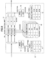
- FIG.7 is a diagram showing a configuration of a queue control unit 12 according to a first embodiment of the present invention.
- the queue control unit 12 includes at least one queue 13, a write control unit 14, a read control unit 15, a queue allotting table 17, and a shaping table 18.
- the write control unit 14 of the queue control unit 12 is arranged to read the VLAN tags V1 and V2 of a received frame, and access the queue allotting table 17 to search for a corresponding queue 13 using the VLAN tags V1 and V2 as key information.
- the queue allotting table 17 indicates a correspondence between VLAN tags V1 and V2 and a queue. After determining the corresponding queue 13 based on the VLAN tags V1 and V2, the write control unit 14 stores the received frame in the corresponding queue 13.
- the queue control unit 12 allots a received frame according to its VLAN tags V1 and V2.
- the read control unit 15 of the queue control unit 12 is arranged to search for a corresponding read rate for a queue 13 from the shaping table 18 and read a frame from the queue 13 at the corresponding read rate. In this way, the queue control unit 12 may be able to control a frame read rate for each queue 13.
- FIG.8 is a diagram showing a configuration of a queue control unit 12 according to a second embodiment of the present invention.
- the queue control unit 12 of FIG.8 includes at least one queue 13, a write control unit 14, a read control unit 15, a queue allotting table 17, a shaping table 18, a policing table 19, and at least one policer 20.
- the write control unit 14 of the queue control unit 12 is arranged to read the VLAN tag V2 of a received frame and access the queue allotting table 17 to search for a corresponding queue for the frame using the VLAN tag V2 as key information.
- the queue allotting table 17 indicates a correspondence between a VLAN tag V2 and a queue 13.
- the queue control unit 12 allots a received frame to a corresponding queue 13 according to its VLAN tag V2; namely, its route.
- policing of traffic flow is conducted with respect to each VLAN tag V1; namely, for each group, so that a particular group may be prevented from dominating the read band.
- the queue control unit 12 of FIG.8 includes a policer 20 before each queue 13 to conduct policing of a frame being stored in each queue 13 to thereby control the traffic flow of a frame according to its VLAN tag V1.
- the policer 20 is arranged to read the VLAN tag V1 of a received frame and access the policing table 19, which indicates a correspondence between a VLAN tag V1 and an input rate, to determine a corresponding input rate for the received frame using the read VLAN tag V1 as key information. It is noted that the policing table 19 may be individually set for each policer 20. In this way, the queue control unit 12 may allot a received frame according to its VLAN tag V2 and control the traffic flow of the allotted frame according to its VLAN tag V1.
- a frame that is allotted according to its VLAN tag V2 may be stored in its corresponding queue 13. It is noted that in the example of FIG.8, different queues 13 are provided with respect to different VLAN tags V2, and thereby, the number of queues to be provided in the queue control unit 12 may be reduced compared to the example of FIG.7.
- the read control unit 15 of the queue control unit 12 is arranged to access the shaping table 18 to search for a corresponding read rate for a frame from the respective read rates set to the queues 13 in the shaping table 18, and read the frame from its corresponding queue 13 at the corresponding read rate. In this way, the queue control unit 12 is able to control a frame read rate for each queue 13.
- FIG.9 is a diagram showing a configuration of a queue control unit 12 according to a third embodiment of the present invention.
- the shaping table 18 and the policing table 19 are set differently from the example of FIG.8.
- the policing table 19 indicates a maximum rate for each VLAN tag or each group. Accordingly, the policer 20 conducts policing of a frame to be stored in a queue 13 according to a maximum rate set for the corresponding group of the frame referring to the policing table 19. In the shaping table 18 of the present example, the sum of the maximum rates for the corresponding groups of frames stored in a queue 13 is set as the read rate of the queue 13.
- the read rate of the corresponding queue 13 is set to 130 Mb/s in the shaping table 18.
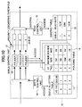
- FIG.10 is a diagram showing a configuration of a queue control unit 12 according to a fourth embodiment of the present invention.
- the shaping table 18 and the policing table 19 are set differently with respect to the examples of FIGS.8 and 9.
- the policing table 19 sets a minimum rate and a maximum rate for each VLAN tag V1; namely, for each group.
- the policer 20 is arranged to conduct policing of a frame to be stored in a queue 13 according to the minimum rate and the maximum rate for the corresponding group of the frame set in the policing table 19.
- traffic with flow rate that is within the range between the minimum rate and the maximum rate has a priority discarding bit set thereto so as to be discarded with priority in its corresponding queue 13.
- a priority discarding threshold value is set, and when traffic in a queue 13 exceeds the priority discarding threshold value, a frame with the priority discarding bit may be discarded with priority.
- traffic below the minimum rate may be read with priority when traffic in a queue 13 exceeds the priority discarding threshold value.
- the read rate for the queue 13 is set to 30 ⁇ 130 Mb/s in the shaping table 18. It is noted that a high read rate set in the shaping table 18 enables efficient passage of the best effort traffic while a low read rate tends to degrade the passage of the best effort traffic.
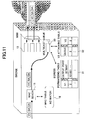
- FIG.11 is a diagram illustrating an exemplary operation of the bridge apparatus 1a in response to receiving a non-learned frame. It is noted that basic operation steps conducted in the present example are identical to those described in relation to the example of FIG.6, and their descriptions are omitted accordingly.
- the MAC search unit 11 reads the DA and the VLAN tag V1 of a received frame and accesses the MAC table 16 to search for a corresponding VLAN tag V2 and a port to which the frame is to be output using the read DA and the VLAN tag V1 as key information.
- the received frame corresponds to a non-learned frame, and thereby, the MAC search unit 11 is unable to find the corresponding VLAN tag V2 and the port to which the frame is to be output from the MAC table 16.
- the MAC search unit accesses a forwarding table 31 using the VLAN tag V1 of the received frame as key information to acquire a bit map of the physical and logical ports belonging to the VLAN tag V1 so that it may multicast the frame to the VLAN tag V1 domain.
- the frame may be accumulated in a multicast queue 30 to wait for a readout opportunity to each port.
- a read control unit may be able to transmit a frame with a VLAN tag V2 attached thereto even when the frame is received as a non-learned frame.
- FIG.12 is a diagram showing an exemplary configuration of the bridge apparatuses 1b and 1c.
- the bridge apparatuses 1b and 1c each include a MAC learning unit 40, a VLAN tag V2 removing unit 41, a MAC search unit 42, a VLAN tag V1 removing unit 43, and a MAC table 44.
- V1 the VLAN tag
- MAC table 44 a MAC table 44.
- the MAC search unit 40 of the bridge apparatus 1b or 1c is arranged to read the VLAN tag V1, the VLAN tag V2, and the SA of the received frame, learn the correspondence between the SA, the VLAN tag V1, the port receiving the frame, and the VLAN tag V2, and store the learned information in the MAC table 44.
- the MAC table 44 associates a set of the SA and the VLAN tag V1 with a set of the corresponding output port and the VLAN tag V2.
- the MAC leaning unit 40 transmits the learned frame to the VLAN tag V2 removing unit 41.
- the VLAN tag V2 removing unit removes the VLAN tag V2 from the received frame and transmits the resulting frame to the MAC search unit 42.
- the MAC search unit 42 is arranged to read the VLAN tag of a received frame, and access the MAC table 44 to determine a corresponding port to which the frame is to be output using the VLAN tag V1 as key information.
- the VLAN tag V1 removing unit 43 receives the frame from the MAC search unit 42, removes the VLAN tag V1 from the received frame, and transmits the resulting frame to the corresponding station 3b or 3c.
- the MAC search unit 42 of the bridge apparatus 1b or 1c transmits the frame with the VLAN tag V2 removed therefrom to a subsequent apparatus where the VLAN tag V1 may be removed. Then, the resulting frame is transmitted to the corresponding station 3b or 3c.
Landscapes
- Engineering & Computer Science (AREA)
- Computer Networks & Wireless Communication (AREA)
- Signal Processing (AREA)
- Computer Security & Cryptography (AREA)
- Data Exchanges In Wide-Area Networks (AREA)
- Small-Scale Networks (AREA)
Abstract
A communication apparatus is provided for
constructing a virtual group with a portion of
information appliances provided over a network. The
communication apparatus includes a tag attaching
unit for attaching to a frame received at an input
port a group identification tag for identifying the
group to which the frame belongs and a route
identification tag for identifying the route of the
frame, a queue for storing the frame according to
the group identification tag and the route
identification tag attached to the frame, and a read
control unit for controlling the read rate for
reading the frame from the queue.
Description
The present invention relates generally to a
communication apparatus and a band control method,
and particularly to a communication apparatus for
constructing a virtual group formed by a portion of
information appliances implemented over a network.
In a network constructed by the Ethernet
(registered trademark) such as a LAN, virtual LAN
(VLAN) technology may be used to construct a virtual
group with a portion of information appliances
(stations) provided in a LAN.
In the VLAN technology, a physical network
structure and a logical network structure are
separated so that stations residing over physically
separate segments may be grouped into one virtual
segment. Such VLAN technology is defined by the
IEEE 802.1Q standard, and presently, two types of
VLAN technology exist, namely, the port VLAN and the
tag VLAN.
Port VLAN involves assigning LAN numbers to the
ports of bridge apparatuses such as switching hubs,
and arranging traffic flow such that each port only
receives traffic designated for its corresponding
group with its corresponding VLAN number. Port VLAN
enables separation of traffic into physical ports,
and may therefore be suitable for fields such as
security and network management.
Tag VLAN involves attaching two bytes of
information called a 'VLAN tag' to a frame, and
setting a VLAN number (VLAN ID) for identifying the
group to which the frame belongs. Tag VLAN enables
plural groups to share one physical link. The VLAN
tag is used as an identifier for identifying a
corresponding group of a frame.
In recent years and continuing, application of
the Ethernet to a metropolitan area network (MAN) is
being contemplated. Such a MAN may be constructed
by an electronic communications company (carrier) to
provide network service to a user.
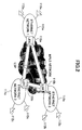
FIG.1 illustrates an exemplary configuration of
an Ethernet service scheme in a MAN. In the MAN
shown in FIG.1, a virtual group (user A) is made up
of stations 102a~102c, which constitute a portion of
a LAN constructed by the Ethernet (to be simply
referred to as Ethernet network hereinafter).
In the present example, a VLAN tag is assigned
to user A so that bridge apparatuses 100a~100c and
101 within the Ethernet network may use the VLAN tag
to realize frame transmission between the stations
102a~102c. The VLAN tag is used as an identifier to
identify a corresponding group of a user (i.e.
subscriber), and in this way, band and other QoS
(quality of service) may be provided to a given
group according to its VLAN tag.
Also, technology exists for connecting plural
Ethernet networks by an MPLS (Multiprotocol Label
Switching) network, such technology being referred
to as EoMPLS (Ethernet over MPLS). EoMPLS involves
attaching an identifier called a 'label' to a frame
within an MPLS network, and conducting frame
transmission based on this label.
FIG.2 shows an exemplary configuration of an
EoMPLS network. In the example of FIG.2, a virtual
group is made up of stations 112a~112c corresponding
to portions of Ethernet networks 111a~111c,
respectively. The Ethernet networks 111a~111c are
interconnected by an LSP (Label Switch Path) within
the MPLS network. The Ethernet networks 111a~111c
are connected to the MPLS via LER (Label Edge
Router) 110a~110c, respectively.
In the present example, an LSP may be
established between the Ethernet networks 111a~111c
by using EoMPLS technology, and thereby, a desired
band may be secured as a reserved band in each LSP
to realize band control betweeen the Ethernet
networks 111a~111c.
However, in the case of an Ethernet service
scheme in a MAN as is illustrated in FIG.1, the VLAN
tag is used as an identifier for identifying a
corresponding group of a user, and consequently,
problems such as those described below are created.
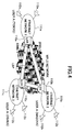
Referring to FIG.3, if user A subscribes to an
Ethernet service at three different locations,
namely, Tokyo headquarters, Nagoya branch office,
and Osaka branch office, for example, the reserved
band is equally distributed between these locations.
In a WAN as illustrated in FIG.3, the group
corresponding to user A may be identified by the
VLAN tag; however, the respective locations of the
group may not be identified and thereby band usage
may not be controlled with respect to the different
locations.
For example, if the reserved band corresponds
to 100 Mb/s, it is not possible to control usage of
the band so that 80 Mb/s may be used between the
Tokyo headquarters and the Osaka branch office and
20 Mb/s between the Tokyo headquarters and the
Nagoya branch office. In other words, in the
present example, the bridge apparatuses 100a~100c
and 101 are merely capable of handling traffic as
that designated for user A and are unable to
recognize the different locations belonging to the
group of user A.
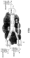
Referring to FIG.4, in the case of using EoMPLS
technology as is illustrated in FIG.2, an LSP may be
established between the Ethernet networks, and a
desired band may be set as the reserved band for
each LSP so that band usage between the respective
locations (base) may be suitably controlled.
For example, if the reserved band is 100 Mb/s,
band usage may be controlled so that 80 Mb/s is used
between the Tokyo head quarters and the Osaka branch
office, and 20 Mb/s is used between the Tokyo head
quarters and the Nagoya branch office.
However, the MPLS network requires complicated
network designing. Also, in the EoMPLS technology,
the frame being transmitted over the Ethernet
network is encapsulated by the frame being
transmitted over the MPLS network, thereby resulting
in a large overhead.
The present invention has been conceived in
response to the one or more problems of the related
art and its object is to provide a communication
apparatus and a band control method for enabling
band control of bases within a virtual group that is
constructed by a portion of information appliances
provided over a network.
To achieve the above-described object, the
present invention, according to one aspect, provides
a communication apparatus that constructs a virtual
group with a portion of information appliances
provided over a network, the apparatus including:
In a communication apparatus according to an
aspect of the present invention, a group
identification tag and a route identification tag
are attached to a frame and band control may be
realized according to the route identification tag.
Thereby, band control may be easily conducted for
the respective bases of a virtual group formed by a
portion of information appliances provided over a
network.
According to a preferred embodiment of the
present invention, the communication apparatus of
the present invention further includes:
In a communication apparatus according to the
present embodiment, traffic flow of a frame to be
stored in a queue may be controlled for each group
identification tag and frames with the same route
may be stored in the same queue so that the number
of queues may be reduced.
According to another preferred embodiment of
the present invention, the traffic flow control unit
is configured to control a maximum flow of the frame
to be stored in the queue according to the group
identification tag attached to the frame.
In a communication apparatus according the
present embodiment, the maximum flow of a frame to
be stored in a queue may be controlled for each
group identification tag so that band resources may
be fairly distributed among differing groups of
frames within a given queue.
According to another preferred embodiment of
the present invention, the traffic control unit is
configured to control a maximum flow and a minimum
flow of the frame to be stored in the queue
according to the group identification tag attached
to the frame.
In a communication apparatus according to the
present embodiment, the minimum flow and the maximum
flow of a frame to be stored in a queue may be
controlled for each group identification tag.
Thereby, a minimum band may be secured for each
corresponding group of a frame that is stored in a
given queue, while an unused band that is secured
for a group may be allotted to another group.
According to another preferred embodiment of
the present invention, when the traffic flow of the
frame is greater than or equal to the minimum flow
and is less than or equal to the maximum flow, the
traffic flow control unit attaches to the frame an
indicator for indicating that the frame is to be
discarded with priority upon congestion of the queue.
In a communication apparatus according to the
present embodiment, a frame with a traffic flow that
is greater than or equal to a minimum flow and is
less than or equal to a maximum flow may be
discarded with priority upon congestion of a queue,
and thereby, a frame of a group that is assigned a
band having a traffic flow below the minimum flow
rate may be read with priority.
According to another preferred embodiment of
the present invention, the route identification tag
is attached to a position corresponding to a
position in the frame to which the group
identification tag is attached prior to the
attachment of the route identification tag.
In a communication apparatus according to the
present embodiment, a route identification tag is
attached to a frame at a position corresponding to
where a group identification tag is previously
positioned, and thereby, a function of the
communication apparatus of transferring a frame
according to its group identification tag may be
used to transmit a frame to another communication
apparatus according to the route identification tag
attached to the frame.
Also, the present invention, according to
another aspect, provides a communication apparatus
that constructs a virtual group with a portion of
information appliances provided over a network, the
apparatus comprising:
In a communication apparatus according to an
aspect of the present invention, a route
identification tag is removed from a frame having a
group identification tag and a route identification
tag attached thereto, and thereby, a frame that is
converted back to its original state may be output
to an output port.
Also, the present invention, according to
another aspect, provides a band control method for
controlling a communication apparatus that
constructs a virtual group with a portion of
information appliances provided over a network, the
method comprising:
In a band control method according to an aspect
of the present invention, a group identification tag
and a route identification tag are attached to a
received frame to realize band control based on the
route identification tag of a frame. Thereby, band
control may be easily realized for the respective
bases of a virtual group formed by a portion of
information appliances provided over a network.
Also, the present invention, according to
another aspect, provides a band control method for
controlling a communication apparatus that
constructs a virtual group with a portion of
information appliances provided over a network, the
method comprising:
In a band control method according to an aspect
of the present invention, a route identification tag
is removed from a frame having a group
identification tag and a route identification tag
attached thereto, and thereby, a frame that is
converted back to its original state may be output
to an output port.
Other objects, features and advantages of the
present invention will become more apparent from the
following detailed description when read in
conjunction with the accompanying drawings.
In the following, preferred embodiments of the
present invention are described with reference to
the accompanying drawings.
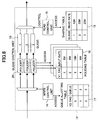
FIG.5 shows an exemplary configuration of a
network using communication apparatuses according to
an embodiment of the present invention; more
specifically, FIG.5 shows an exemplary Ethernet
network using bridge apparatuses. In the following
description, an example is described in which a user
A having base points at Tokyo headquarters, Nagoya
branch office, and Osaka branch office establishes
connection by assigning 20 Mb/s between the Tokyo
headquarters and the Nagoya branch office and 80
Mb/s between the Tokyo headquarters and the Osaka
branch office.
In a case where user A subscribes to Ethernet
service at three locations; namely, the Tokyo
headquarters, the Nagoya branch office, and the
Osaka branch office, station 3a at the Tokyo
headquarters, station 3b at the Nagoya branch office,
and station 3c at the Osaka branch office form a
virtual group.
As is shown in the drawing, station 3a is
connected to a bridge apparatus 1a; station 3b is
connected to a bridge apparatus 1b, and station 3c
is connected to a bridge apparatus 1c. The bridge
apparatuses 1a~1c are interconnected via a bridge
apparatus 2.
According to the present embodiment, a first
VLAN tag V1 for identifying a user group and a
second VLAN tag V2 for identifying a frame route are
assigned to a frame being transmitted between two of
the bridge apparatuses 1a~1c. In FIG.5, VLAN tag
V1=1 is set for the group corresponding to user A,
VLAN tag V2=3 is set for the route between the Tokyo
headquarters and the Nagoya branch office, and VLAN
tag V2=5 is set for the route between the Tokyo head
quarters and the Osaka branch office. It is noted
that in FIG.5, frames being transmitted between two
of the bridge apparatuses 1a~1c are only represented
by their VLAN tags V1 and V2, and other components
of these frames are omitted from the drawing for the
sake of simplicity.
For example, in the case of a port VLAN, a
frame transmitted from station 3a of the Tokyo
headquarters may be supplied to the bridge apparatus
1a. In turn, the bridge apparatus 1a may attach to
this frame a VLAN number 1 that is assigned to the
port receiving the frame as a VLAN tag V1.
In the case of a tag VLAN, a frame transmitted
from the station 3a at the Tokyo headquarters is
supplied to the bridge apparatus 1a after a VLAN tag
V1 is attached to the frame at a prior stage
apparatus.
Then, the bridge apparatus 1a attaches a VLAN
tag V2 to the frame according to the route of the
received frame having a VLAN tag V1 attached thereto.
For example, a frame that is to be transmitted from
station 3a to station 3b may have a VLAN tag V1=1
and a VLAN tag V2=3 attached thereto, and a frame
that is to be transmitted from station 3a to station
3c may have a VLAN tag V1=1 and a VLAN tag V2=5
attached thereto.
Then, the bridge apparatus 1a stores (buffers)
the frame with the VLAN tags V1 and V2 attached
thereto in a queue according to the VLAN tags V1 and
V2. In the example shown in FIG.5, the VLAN tag V1
and V2 are attached to a frame within the bridge
apparatus 1a; however, other embodiments are
possible in which plural bridge apparatuses are used
to attach the VLAN tags V1 and V2 to a frame, for
example.
It is noted that band control for the queues
storing frames according to their VALN tags may be
realized by WRR (Weighted Round Robin). For example,
a frame stored in a queue for a VLAN tag V1=1 and a
VLAN tag V2=3 may be read at 20 Mb/s, whereas a
frame stored in a queue for a VLAN tag V1=1 and a
VLAN tag V2=5 may be read at 80 Mb/s. A frame that
is read from a queue according to the band set in a
manner described above may then be transmitted to
the bridge apparatus 2.
In the present example, a frame transmitted
from the bridge apparatus 1a is received at a tag
VLAN port of the bridge apparatus 2. The bridge
apparatus 2 is arranged to identify the route of a
received frame by referring to its outermost VLAN
tag, namely, its VLAN tag V2. It is noted that the
bridge apparatus is arranged to identify a domain of
a frame by simply referring to the outermost VLAN
tag of a frame, and the present embodiment uses such
feature of the bridge apparatus to identify the
route of a frame. More specifically, by stacking a
VLAN tag V2 on a VLAN tag V1 so that the VLAN tag V2
is positioned at an outermost edge of a frame, the
bridge apparatus 2 may identify the route of a frame
by simply referring to the outer most VLAN tag V2 of
a received frame without recognizing the existence
of two stacks of tag information.
The bridge apparatus 1b or 1c is arranged to
receive a frame from the bridge apparatus 2 and
remove the second VLAN tag V2 from the received
frame. In the case of the port LAN, the bridge
apparatus 1b or 1c removes the VLAN tag V2 and then
the VLAN tag V1 from the frame, and transmits the
resulting frame to the corresponding station 3b or
3c. In the case of the tag VLAN, the bridge
apparatus 1b or 1c removes the VLAN tag V2 after
which it transmits the frame to a subsequent
apparatus where the VLAN tag V1 may be removed.
Then, the resulting frame is transmitted to the
corresponding station 3b or 3c.
FIG.6 shows an exemplary configuration of the
bridge apparatus 1a. According to the present
example, the bridge apparatus 1a includes a VLAN tag
V1 attaching unit 10, a MAC search unit 11, a queue
control unit 12, at least one queue 13, a write
control unit 14, a read control unit 15, and a MAC
table 16. It is noted that in the example of FIG.6,
only a VLAN tag V1, a VLAN tag V2, a DA (destination
address), and a SA (source address) of a frame
passing through the bridge apparatus 1a are
indicated, and other components of the frame are
omitted from the drawing for the sake of simplicity.
In the example of FIG.5 in which the station 3a
is directly connected to the bridge apparatus 1a and
the VLAN corresponds to a port VLAN, the VLAN tag V1
attaching unit 10 attaches a VLAN tag V1 to a frame
received from the station 3a and transmits the frame
with the VLAN tag V1 to the MAC search unit 11.
On the other hand, when the station 3a is not
directly connected to the bridge apparatus 1a in
which case the VLAN corresponds to a tag VLAN, a
frame having a VLAN tag V1 attached thereto in a
prior stage apparatus is transmitted to the MAC
search unit 11.
According to the present example, the MAC
search unit 11 is arranged to read the DA and the
VLAN tag V1 of a received frame, and access a MAC
table 16 to search for a corresponding VLAN tag V2
and a port to which the frame is to be output using
the DA and the VLAN tag V1 as key information. The
MAC table 16 indicates the correspondence between a
DA, a VLAN tag V1, a port, and a VLAN tag V2. After
determining the corresponding VLAN tag V2 and output
port, the MAC search unit 11 attaches the
corresponding VLAN tag V2 to the received frame and
transmits this frame to the queue control unit 12.
In turn, the write control unit 14 included in
the queue control unit 12 reads the VLAN tags V1 and
V2 from the received frame, and searches for a queue
13 to which the frame is to be stored based on the
VLAN tags V1 and V2 as is described in detail below.
Then, the queue control unit 12 stores the frame in
the corresponding queue 13.
The read control unit 15 included in the queue
control unit 12 searches for a corresponding read
rate for reading the frame. It is noted that a
predetermined read rate may be set for each queue,
so that a frame may be read from its corresponding
queue 13 at a corresponding read rate. In this way,
the queue control unit 12 is able to control a frame
read rate for each queue.
In the following, the operation of the queue
control unit 12 is described in greater detail.
FIG.7 is a diagram showing a configuration of a
queue control unit 12 according to a first
embodiment of the present invention. In the example
of FIG.7, the queue control unit 12 includes at
least one queue 13, a write control unit 14, a read
control unit 15, a queue allotting table 17, and a
shaping table 18.
In the present example, the write control unit
14 of the queue control unit 12 is arranged to read
the VLAN tags V1 and V2 of a received frame, and
access the queue allotting table 17 to search for a
corresponding queue 13 using the VLAN tags V1 and V2
as key information. The queue allotting table 17
indicates a correspondence between VLAN tags V1 and
V2 and a queue. After determining the corresponding
queue 13 based on the VLAN tags V1 and V2, the write
control unit 14 stores the received frame in the
corresponding queue 13.
In the example of FIG.7, different queues 13
are provided for different combinations of the VLAN
tags V1 and V2. Thus, the queue control unit 12
allots a received frame according to its VLAN tags
V1 and V2.
Also, in the present example, the read control
unit 15 of the queue control unit 12 is arranged to
search for a corresponding read rate for a queue 13
from the shaping table 18 and read a frame from the
queue 13 at the corresponding read rate. In this
way, the queue control unit 12 may be able to
control a frame read rate for each queue 13.
FIG.8 is a diagram showing a configuration of a
queue control unit 12 according to a second
embodiment of the present invention. The queue
control unit 12 of FIG.8 includes at least one queue
13, a write control unit 14, a read control unit 15,
a queue allotting table 17, a shaping table 18, a
policing table 19, and at least one policer 20.
According to the present example, the write
control unit 14 of the queue control unit 12 is
arranged to read the VLAN tag V2 of a received frame
and access the queue allotting table 17 to search
for a corresponding queue for the frame using the
VLAN tag V2 as key information. The queue allotting
table 17 indicates a correspondence between a VLAN
tag V2 and a queue 13. The queue control unit 12
allots a received frame to a corresponding queue 13
according to its VLAN tag V2; namely, its route.
In an arrangement according to the present
example, policing of traffic flow is conducted with
respect to each VLAN tag V1; namely, for each group,
so that a particular group may be prevented from
dominating the read band. The queue control unit 12
of FIG.8 includes a policer 20 before each queue 13
to conduct policing of a frame being stored in each
queue 13 to thereby control the traffic flow of a
frame according to its VLAN tag V1.
The policer 20 is arranged to read the VLAN tag
V1 of a received frame and access the policing table
19, which indicates a correspondence between a VLAN
tag V1 and an input rate, to determine a
corresponding input rate for the received frame
using the read VLAN tag V1 as key information. It
is noted that the policing table 19 may be
individually set for each policer 20. In this way,
the queue control unit 12 may allot a received frame
according to its VLAN tag V2 and control the traffic
flow of the allotted frame according to its VLAN tag
V1.
After the policing conducted by the policer 20,
a frame that is allotted according to its VLAN tag
V2 may be stored in its corresponding queue 13. It
is noted that in the example of FIG.8, different
queues 13 are provided with respect to different
VLAN tags V2, and thereby, the number of queues to
be provided in the queue control unit 12 may be
reduced compared to the example of FIG.7.
Also, in the present example, the read control
unit 15 of the queue control unit 12 is arranged to
access the shaping table 18 to search for a
corresponding read rate for a frame from the
respective read rates set to the queues 13 in the
shaping table 18, and read the frame from its
corresponding queue 13 at the corresponding read
rate. In this way, the queue control unit 12 is
able to control a frame read rate for each queue 13.
FIG.9 is a diagram showing a configuration of a
queue control unit 12 according to a third
embodiment of the present invention. In the queue
control unit 12 of FIG.9 the shaping table 18 and
the policing table 19 are set differently from the
example of FIG.8.
Specifically, in FIG.9, the policing table 19
indicates a maximum rate for each VLAN tag or each
group. Accordingly, the policer 20 conducts
policing of a frame to be stored in a queue 13
according to a maximum rate set for the
corresponding group of the frame referring to the
policing table 19. In the shaping table 18 of the
present example, the sum of the maximum rates for
the corresponding groups of frames stored in a queue
13 is set as the read rate of the queue 13.
By setting the sum of the maximum rates of the
corresponding groups of the frames stored in a queue
13 as the read rate of the queue 13 in the shaping
table 18, traffic passing through a corresponding
policer 20 may be transmitted without being
discarded.
For example, in a case where frames belonging
to groups of users A and B are stored in the same
queue 13, if the maximum rate set for the group of
user A is 50 Mb/s, and the maximum rate set for the
group of user B is 80 Mb/s, the read rate of the
corresponding queue 13 is set to 130 Mb/s in the
shaping table 18.
FIG.10 is a diagram showing a configuration of
a queue control unit 12 according to a fourth
embodiment of the present invention. In the queue
control unit 12 of FIG.10, the shaping table 18 and
the policing table 19 are set differently with
respect to the examples of FIGS.8 and 9.
According to the present example, the policing
table 19 sets a minimum rate and a maximum rate for
each VLAN tag V1; namely, for each group. The
policer 20 is arranged to conduct policing of a
frame to be stored in a queue 13 according to the
minimum rate and the maximum rate for the
corresponding group of the frame set in the policing
table 19. In this example, traffic with flow rate
that is within the range between the minimum rate
and the maximum rate (best effort traffic) has a
priority discarding bit set thereto so as to be
discarded with priority in its corresponding queue
13.
Also, in each queue 13, a priority discarding
threshold value is set, and when traffic in a queue
13 exceeds the priority discarding threshold value,
a frame with the priority discarding bit may be
discarded with priority. By giving priority for
discarding a frame having a priority discarding bit
over other frames, traffic below the minimum rate
may be read with priority when traffic in a queue 13
exceeds the priority discarding threshold value.
For example, in the case where frames belonging
to groups of users A and B are stored in the same
queue 13, if the maximum rate and minimum rate for
the group of user A are set to 50 Mb/s and 20 Mb/s,
respectively, and the maximum rate and the minimum
rate set for the group of user B are 80 Mb/s and 20
Mb/s, respectively, the read rate for the queue 13
is set to 30~130 Mb/s in the shaping table 18. It
is noted that a high read rate set in the shaping
table 18 enables efficient passage of the best
effort traffic while a low read rate tends to
degrade the passage of the best effort traffic.
In the following, an operation of the bridge
apparatus 1a in response to receiving a non-learned
frame is described with reference to FIG.11.
FIG.11 is a diagram illustrating an exemplary
operation of the bridge apparatus 1a in response to
receiving a non-learned frame. It is noted that
basic operation steps conducted in the present
example are identical to those described in relation
to the example of FIG.6, and their descriptions are
omitted accordingly.
In the present example, the MAC search unit 11
reads the DA and the VLAN tag V1 of a received frame
and accesses the MAC table 16 to search for a
corresponding VLAN tag V2 and a port to which the
frame is to be output using the read DA and the VLAN
tag V1 as key information. In the present example,
the received frame corresponds to a non-learned
frame, and thereby, the MAC search unit 11 is unable
to find the corresponding VLAN tag V2 and the port
to which the frame is to be output from the MAC
table 16.
In such a case, the MAC search unit accesses a
forwarding table 31 using the VLAN tag V1 of the
received frame as key information to acquire a bit
map of the physical and logical ports belonging to
the VLAN tag V1 so that it may multicast the frame
to the VLAN tag V1 domain. In such an operation,
the frame may be accumulated in a multicast queue 30
to wait for a readout opportunity to each port.
When a readout opportunity is granted, a
corresponding VLAN tag V2 for the queue from which a
frame is to be read is read out from the VLAN tag
attaching table 32. In this way, a read control
unit may be able to transmit a frame with a VLAN tag
V2 attached thereto even when the frame is received
as a non-learned frame.
FIG.12 is a diagram showing an exemplary
configuration of the bridge apparatuses 1b and 1c.
According to the present example, the bridge
apparatuses 1b and 1c each include a MAC learning
unit 40, a VLAN tag V2 removing unit 41, a MAC
search unit 42, a VLAN tag V1 removing unit 43, and
a MAC table 44. It is noted that in FIG.12, only
the VLAN tag V1, the VLAN tag V2, the DA, and the SA
are indicated in the frame passing through the
bridge apparatus 1b or 1c, and the rest of the
components of the frame are omitted from the
drawings for the sake of simplicity.
According to the present example, upon
receiving a frame from the bridge apparatus 2, the
MAC search unit 40 of the bridge apparatus 1b or 1c
is arranged to read the VLAN tag V1, the VLAN tag V2,
and the SA of the received frame, learn the
correspondence between the SA, the VLAN tag V1, the
port receiving the frame, and the VLAN tag V2, and
store the learned information in the MAC table 44.
It is noted that the MAC table 44 associates a
set of the SA and the VLAN tag V1 with a set of the
corresponding output port and the VLAN tag V2.
After storing the learned information, the MAC
leaning unit 40 transmits the learned frame to the
VLAN tag V2 removing unit 41. In turn, the VLAN tag
V2 removing unit removes the VLAN tag V2 from the
received frame and transmits the resulting frame to
the MAC search unit 42.
The MAC search unit 42 is arranged to read the
VLAN tag of a received frame, and access the MAC
table 44 to determine a corresponding port to which
the frame is to be output using the VLAN tag V1 as
key information.
If the corresponding port is a port VLAN, the
VLAN tag V1 removing unit 43 receives the frame from
the MAC search unit 42, removes the VLAN tag V1 from
the received frame, and transmits the resulting
frame to the corresponding station 3b or 3c. On the
other hand, if the corresponding port is a tag VLAN,
the MAC search unit 42 of the bridge apparatus 1b or
1c transmits the frame with the VLAN tag V2 removed
therefrom to a subsequent apparatus where the VLAN
tag V1 may be removed. Then, the resulting frame is
transmitted to the corresponding station 3b or 3c.
Further, it is noted that the present invention
is not limited to the specific embodiments described
above, and variations and modifications may be made
without departing from the scope of the present
invention.
Claims (9)
- A communication apparatus that constructs a virtual group with a portion of information appliances provided over a network, the apparatus being characterized by comprising:a tag attaching unit configured to attach to a frame received at an input port a group identification tag for identifying the group to which the frame belongs and a route identification tag for identifying a route of the frame;a queue configured to store the frame according to the group identification tag and the route identification tag attached to the frame;a read control unit configured to control a read rate for reading the frame from the queue.
- The communication apparatus as claimed in claim 1, further comprising:wherein the frame is stored in the queue according to the route identification tag attached to the frame.a traffic flow control unit configured to control traffic flow of the frame to be stored in the queue according to the group identification tag attached to the frame;
- The communication apparatus as claimed in claim 2, wherein the traffic flow control unit is configured to control a maximum flow of the frame to be stored in the queue according to the group identification tag attached to the frame.
- The communication apparatus as claimed in claim 2, wherein the traffic control unit is configured to control a maximum flow and a minimum flow of the frame to be stored in the queue according to the group identification tag attached to the frame.
- The communication apparatus as claimed in claim 4, wherein when the traffic flow of the frame is greater than or equal to the minimum flow and is less than or equal to the maximum flow, the traffic flow control unit attaches to the frame an indicator for indicating that the frame is to be discarded with priority upon congestion of the queue.
- The communication apparatus as claimed in claim 1, wherein the route identification tag is attached to a position corresponding to a position in the frame to which the group identification tag is attached prior to the attachment of the route identification tag.
- A communication apparatus that constructs a virtual group with a portion of information appliances provided over a network, the apparatus being characterized by comprising:a tag removing unit configured to remove from a frame received at an input port a route identification tag for identifying a route of the frame; andan output unit configured to read from the frame a group identification tag for identifying the group to which the frame belongs and output the frame to an output port according to the group identification tag.
- A band control method for controlling a communication apparatus that constructs a virtual group with a portion of information appliances provided over a network, the method being characterized by comprising:a tag attaching step of attaching to a frame received at an input port a group identification tag for identifying the group to which the frame belongs and a route identification tag for identifying a route of the frame;a buffering step of storing the frame in a queue according to the group identification tag and the route identification tag attached to the frame; anda reading step of reading the frame from the queue according to a read rate set for the queue.
- A band control method for controlling a communication apparatus that constructs a virtual group with a portion of information appliances provided over a network, the method being characterized by comprising:a tag removing step of removing from a frame received at an input port a route identification tag for identifying a route of the frame; andan outputting step of reading from the frame a group identification tag for identifying the group to which the frame belongs and outputting the frame to an output port according to the read group identification tag.
Applications Claiming Priority (1)
| Application Number | Priority Date | Filing Date | Title |
|---|---|---|---|
| PCT/JP2002/012677 WO2004051942A1 (en) | 2002-12-03 | 2002-12-03 | Communication device and band control method |
Publications (2)
| Publication Number | Publication Date |
|---|---|
| EP1569389A1 true EP1569389A1 (en) | 2005-08-31 |
| EP1569389A4 EP1569389A4 (en) | 2006-01-18 |
Family
ID=32448993
Family Applications (1)
| Application Number | Title | Priority Date | Filing Date |
|---|---|---|---|
| EP02783756A Withdrawn EP1569389A4 (en) | 2002-12-03 | 2002-12-03 | COMMUNICATION DEVICE AND LOGIC FOR BAND MANAGEMENT |
Country Status (5)
| Country | Link |
|---|---|
| US (1) | US20050175022A1 (en) |
| EP (1) | EP1569389A4 (en) |
| JP (1) | JPWO2004051942A1 (en) |
| CN (1) | CN1640071A (en) |
| WO (1) | WO2004051942A1 (en) |
Cited By (4)
| Publication number | Priority date | Publication date | Assignee | Title |
|---|---|---|---|---|
| WO2006123287A3 (en) * | 2005-05-18 | 2007-02-08 | Koninkl Philips Electronics Nv | Integrated circuit and method of arbitration in a network on an integrated circuit |
| EP1833205A1 (en) * | 2006-03-06 | 2007-09-12 | Fujitsu Ltd. | Band control program, band control device and band control method |
| WO2008118797A1 (en) | 2007-03-27 | 2008-10-02 | Amazon Technologies, Inc. | Configuring intercommunications between computing nodes |
| EP2001172A4 (en) * | 2006-06-16 | 2009-04-01 | Huawei Tech Co Ltd | METHOD, SYSTEM AND DEVICE OF THE ETHERNET EXCHANGE AND TRANSFER TECHNIQUE |
Families Citing this family (28)
| Publication number | Priority date | Publication date | Assignee | Title |
|---|---|---|---|---|
| US7715310B1 (en) | 2004-05-28 | 2010-05-11 | Cisco Technology, Inc. | L2VPN redundancy with ethernet access domain |
| US7643409B2 (en) * | 2004-08-25 | 2010-01-05 | Cisco Technology, Inc. | Computer network with point-to-point pseudowire redundancy |
| JP4654650B2 (en) * | 2004-10-13 | 2011-03-23 | 日本電気株式会社 | Wireless transmission system, wireless transmission device, and wireless transmission method used therefor |
| JP2006211113A (en) * | 2005-01-26 | 2006-08-10 | Mitsubishi Electric Corp | Information collection system and base station used therefor |
| FR2882939B1 (en) * | 2005-03-11 | 2007-06-08 | Centre Nat Rech Scient | FLUIDIC SEPARATION DEVICE |
| US8213435B2 (en) * | 2005-04-28 | 2012-07-03 | Cisco Technology, Inc. | Comprehensive model for VPLS |
| US8194656B2 (en) | 2005-04-28 | 2012-06-05 | Cisco Technology, Inc. | Metro ethernet network with scaled broadcast and service instance domains |
| US9088669B2 (en) * | 2005-04-28 | 2015-07-21 | Cisco Technology, Inc. | Scalable system and method for DSL subscriber traffic over an Ethernet network |
| US7835370B2 (en) | 2005-04-28 | 2010-11-16 | Cisco Technology, Inc. | System and method for DSL subscriber identification over ethernet network |
| US8094663B2 (en) * | 2005-05-31 | 2012-01-10 | Cisco Technology, Inc. | System and method for authentication of SP ethernet aggregation networks |
| US8175078B2 (en) * | 2005-07-11 | 2012-05-08 | Cisco Technology, Inc. | Redundant pseudowires between Ethernet access domains |
| US7889754B2 (en) * | 2005-07-12 | 2011-02-15 | Cisco Technology, Inc. | Address resolution mechanism for ethernet maintenance endpoints |
| US7855950B2 (en) * | 2005-08-01 | 2010-12-21 | Cisco Technology, Inc. | Congruent forwarding paths for unicast and multicast traffic |
| US8169924B2 (en) * | 2005-08-01 | 2012-05-01 | Cisco Technology, Inc. | Optimal bridging over MPLS/IP through alignment of multicast and unicast paths |
| US9088619B2 (en) * | 2005-09-14 | 2015-07-21 | Cisco Technology, Inc. | Quality of service based on logical port identifier for broadband aggregation networks |
| US8085790B2 (en) * | 2006-07-14 | 2011-12-27 | Cisco Technology, Inc. | Ethernet layer 2 protocol packet switching |
| US7961612B2 (en) * | 2006-12-04 | 2011-06-14 | International Business Machines Corporation | Limiting transmission rate of data |
| US8804534B2 (en) * | 2007-05-19 | 2014-08-12 | Cisco Technology, Inc. | Interworking between MPLS/IP and Ethernet OAM mechanisms |
| US8531941B2 (en) | 2007-07-13 | 2013-09-10 | Cisco Technology, Inc. | Intra-domain and inter-domain bridging over MPLS using MAC distribution via border gateway protocol |
| US8077709B2 (en) | 2007-09-19 | 2011-12-13 | Cisco Technology, Inc. | Redundancy at a virtual provider edge node that faces a tunneling protocol core network for virtual private local area network (LAN) service (VPLS) |
| CN102549977B (en) | 2009-09-24 | 2014-11-05 | 日本电气株式会社 | Inter-virtual server communication identification system and inter-virtual server communication identification method |
| US8798059B1 (en) | 2010-12-03 | 2014-08-05 | Juniper Networks, Inc. | Optimizing private virtual local area networks (VLANs) |
| US8650285B1 (en) | 2011-03-22 | 2014-02-11 | Cisco Technology, Inc. | Prevention of looping and duplicate frame delivery in a network environment |
| US20120250694A1 (en) * | 2011-03-28 | 2012-10-04 | Tttech Computertechnik Ag | Centralized traffic shaping for data networks |
| US9473420B2 (en) | 2013-03-13 | 2016-10-18 | International Business Machines Corporation | Metrics and forwarding actions on logical switch partitions in a distributed network switch |
| US9282056B2 (en) * | 2013-03-13 | 2016-03-08 | International Business Machines Corporation | Metrics and forwarding actions on logical switch partitions in a distributed network switch |
| US9313044B2 (en) * | 2014-07-17 | 2016-04-12 | Cisco Technology, Inc. | Multiple mobility domains with VLAN translation in a multi-tenant network environment |
| US11211999B2 (en) * | 2017-12-28 | 2021-12-28 | Hughes Network Systems, Llc | Satellite network virtual LAN usage |
Family Cites Families (12)
| Publication number | Priority date | Publication date | Assignee | Title |
|---|---|---|---|---|
| US5963556A (en) * | 1993-06-23 | 1999-10-05 | Digital Equipment Corporation | Device for partitioning ports of a bridge into groups of different virtual local area networks |
| US6236643B1 (en) * | 1997-02-14 | 2001-05-22 | Advanced Micro Devices, Inc. | Multiport data switch having variable maximum packet length |
| US5978378A (en) * | 1997-09-11 | 1999-11-02 | 3Com Corporation | Method and apparatus for VLAN support |
| US6724767B1 (en) * | 1998-06-27 | 2004-04-20 | Intel Corporation | Two-dimensional queuing/de-queuing methods and systems for implementing the same |
| JP2000341295A (en) * | 1999-05-31 | 2000-12-08 | Fujitsu Ltd | ATM equipment |
| JP4168574B2 (en) * | 2000-06-02 | 2008-10-22 | 株式会社日立製作所 | Packet transfer apparatus, packet transfer control method, and packet transfer apparatus setting method |
| AU2001288399A1 (en) * | 2000-08-24 | 2002-03-04 | Tiara Networks, Inc. | System and method for connecting geographically distributed virtual local area networks |
| JP2002101126A (en) * | 2000-09-25 | 2002-04-05 | Hitachi Ltd | Communication method |
| JP4183379B2 (en) * | 2000-11-27 | 2008-11-19 | 富士通株式会社 | Network and edge router |
| US6618388B2 (en) * | 2001-01-05 | 2003-09-09 | Extreme Networks | Method and system for VMAN protocol |
| WO2002061599A1 (en) * | 2001-01-25 | 2002-08-08 | Crescent Networks, Inc. | Extension of address resolution protocol (arp) for internet protocol (ip) virtual networks |
| US7292581B2 (en) * | 2002-10-24 | 2007-11-06 | Cisco Technology, Inc. | Large-scale layer 2 metropolitan area network |
-
2002
- 2002-12-03 CN CN02829381.9A patent/CN1640071A/en active Pending
- 2002-12-03 JP JP2004556798A patent/JPWO2004051942A1/en active Pending
- 2002-12-03 WO PCT/JP2002/012677 patent/WO2004051942A1/en not_active Ceased
- 2002-12-03 EP EP02783756A patent/EP1569389A4/en not_active Withdrawn
-
2005
- 2005-01-05 US US11/029,010 patent/US20050175022A1/en not_active Abandoned
Cited By (8)
| Publication number | Priority date | Publication date | Assignee | Title |
|---|---|---|---|---|
| WO2006123287A3 (en) * | 2005-05-18 | 2007-02-08 | Koninkl Philips Electronics Nv | Integrated circuit and method of arbitration in a network on an integrated circuit |
| EP1833205A1 (en) * | 2006-03-06 | 2007-09-12 | Fujitsu Ltd. | Band control program, band control device and band control method |
| EP2001172A4 (en) * | 2006-06-16 | 2009-04-01 | Huawei Tech Co Ltd | METHOD, SYSTEM AND DEVICE OF THE ETHERNET EXCHANGE AND TRANSFER TECHNIQUE |
| EP2383944A1 (en) * | 2006-06-16 | 2011-11-02 | Huawei Technologies Co., Ltd. | Ethernet switching and forwarding method, system and apparatus |
| US8072984B2 (en) | 2006-06-16 | 2011-12-06 | Huawei Technologies Co., Ltd. | Ethernet switching and forwarding method, system and apparatus |
| WO2008118797A1 (en) | 2007-03-27 | 2008-10-02 | Amazon Technologies, Inc. | Configuring intercommunications between computing nodes |
| EP2132647A4 (en) * | 2007-03-27 | 2014-10-29 | Amazon Tech Inc | CONFIGURING INTERCOMMUNICATIONS BETWEEN COMPUTER NUDS |
| EP3208724A1 (en) * | 2007-03-27 | 2017-08-23 | Amazon Technologies, Inc. | Configuring intercommunications between computing nodes |
Also Published As
| Publication number | Publication date |
|---|---|
| EP1569389A4 (en) | 2006-01-18 |
| WO2004051942A1 (en) | 2004-06-17 |
| JPWO2004051942A1 (en) | 2006-04-06 |
| CN1640071A (en) | 2005-07-13 |
| US20050175022A1 (en) | 2005-08-11 |
Similar Documents
| Publication | Publication Date | Title |
|---|---|---|
| EP1569389A1 (en) | Communication device and band control method | |
| US6674760B1 (en) | Method and system for implementing end-to-end QoS in packet-switched networks | |
| CN100490422C (en) | Method and device for the classification and redirection of data packets in a heterogeneous network | |
| US6865153B1 (en) | Stage-implemented QoS shaping for data communication switch | |
| US6788682B1 (en) | Mapping of packets between links of trunk groups using Mux/Demux devices | |
| US6990106B2 (en) | Classification and tagging rules for switching nodes | |
| EP1670187B1 (en) | Tagging rules for hybrid ports | |
| CA2352697C (en) | Router device and priority control method for use in the same | |
| JP3788803B2 (en) | L2 switch | |
| US8527674B2 (en) | Data packet switching | |
| US20040267948A1 (en) | Method and system for a network node for attachment to switch fabrics | |
| US20110019572A1 (en) | Method and apparatus for shared shaping | |
| US7502366B1 (en) | Arrangement in a network switch for prioritizing data frames based on user-defined frame attributes | |
| JP2001285333A (en) | Selectable prioritization for data communication switches | |
| US8081633B2 (en) | Network node unit and method for forwarding data packets | |
| US20090292575A1 (en) | Coalescence of Disparate Quality of Service Matrics Via Programmable Mechanism | |
| US6976096B1 (en) | Method and apparatus for controlling the admission of data into a network element | |
| US20120275325A1 (en) | Communication apparatus and method | |
| US9137030B1 (en) | Multicast queueing in a network switch | |
| KR100572696B1 (en) | Broadband subscriber aggregation switch device | |
| US7061919B1 (en) | System and method for providing multiple classes of service in a packet switched network | |
| RU2354058C2 (en) | Switching system and switching method on basis of service class switching | |
| EP2540040B1 (en) | Source based queue selection mechanism in the routing environment | |
| US8953449B2 (en) | Virtual subport data traffic management | |
| US20110064088A1 (en) | Communication apparatus and communication controlling method in ring network |
Legal Events
| Date | Code | Title | Description |
|---|---|---|---|
| PUAI | Public reference made under article 153(3) epc to a published international application that has entered the european phase |
Free format text: ORIGINAL CODE: 0009012 |
|
| 17P | Request for examination filed |
Effective date: 20050202 |
|
| AK | Designated contracting states |
Kind code of ref document: A1 Designated state(s): AT BE BG CH CY CZ DE DK EE ES FI FR GB GR IE IT LI LU MC NL PT SE SI SK TR |
|
| A4 | Supplementary search report drawn up and despatched |
Effective date: 20051206 |
|
| RBV | Designated contracting states (corrected) |
Designated state(s): DE FR GB |
|
| STAA | Information on the status of an ep patent application or granted ep patent |
Free format text: STATUS: THE APPLICATION IS DEEMED TO BE WITHDRAWN |
|
| 18D | Application deemed to be withdrawn |
Effective date: 20080702 |