EP1569374A2 - Interleave parameter processing method - Google Patents
Interleave parameter processing method Download PDFInfo
- Publication number
- EP1569374A2 EP1569374A2 EP20050004021 EP05004021A EP1569374A2 EP 1569374 A2 EP1569374 A2 EP 1569374A2 EP 20050004021 EP20050004021 EP 20050004021 EP 05004021 A EP05004021 A EP 05004021A EP 1569374 A2 EP1569374 A2 EP 1569374A2
- Authority
- EP
- European Patent Office
- Prior art keywords
- div
- value
- row permutation
- permutation pattern
- interleaver
- Prior art date
- Legal status (The legal status is an assumption and is not a legal conclusion. Google has not performed a legal analysis and makes no representation as to the accuracy of the status listed.)
- Granted
Links
- 238000003672 processing method Methods 0.000 title claims 2
- 101100149023 Bacillus subtilis (strain 168) secA gene Proteins 0.000 claims abstract description 16
- 238000000034 method Methods 0.000 claims description 20
- 230000005540 biological transmission Effects 0.000 claims description 8
- 238000004590 computer program Methods 0.000 claims 1
- FFBHFFJDDLITSX-UHFFFAOYSA-N benzyl N-[2-hydroxy-4-(3-oxomorpholin-4-yl)phenyl]carbamate Chemical compound OC1=C(NC(=O)OCC2=CC=CC=C2)C=CC(=C1)N1CCOCC1=O FFBHFFJDDLITSX-UHFFFAOYSA-N 0.000 description 9
- 238000010586 diagram Methods 0.000 description 2
- 239000011159 matrix material Substances 0.000 description 2
- 238000010295 mobile communication Methods 0.000 description 2
- 230000008030 elimination Effects 0.000 description 1
- 238000003379 elimination reaction Methods 0.000 description 1
- 230000006870 function Effects 0.000 description 1
Images


Classifications
-
- H—ELECTRICITY
- H04—ELECTRIC COMMUNICATION TECHNIQUE
- H04L—TRANSMISSION OF DIGITAL INFORMATION, e.g. TELEGRAPHIC COMMUNICATION
- H04L1/00—Arrangements for detecting or preventing errors in the information received
- H04L1/004—Arrangements for detecting or preventing errors in the information received by using forward error control
- H04L1/0056—Systems characterized by the type of code used
- H04L1/0064—Concatenated codes
- H04L1/0066—Parallel concatenated codes
-
- H—ELECTRICITY
- H04—ELECTRIC COMMUNICATION TECHNIQUE
- H04L—TRANSMISSION OF DIGITAL INFORMATION, e.g. TELEGRAPHIC COMMUNICATION
- H04L1/00—Arrangements for detecting or preventing errors in the information received
- H04L1/004—Arrangements for detecting or preventing errors in the information received by using forward error control
- H04L1/0041—Arrangements at the transmitter end
-
- H—ELECTRICITY
- H04—ELECTRIC COMMUNICATION TECHNIQUE
- H04L—TRANSMISSION OF DIGITAL INFORMATION, e.g. TELEGRAPHIC COMMUNICATION
- H04L1/00—Arrangements for detecting or preventing errors in the information received
- H04L1/004—Arrangements for detecting or preventing errors in the information received by using forward error control
- H04L1/0056—Systems characterized by the type of code used
- H04L1/0071—Use of interleaving
Definitions
- the present invention relates to an internal interleaver for turbo coding, referred to as a prime number interleaver, which has been normalized in wideband DS-CDMA (W-CDMA) that has been standardized as one of radio access networks (RAN) for a third-generation mobile communication system (IMT2000).
- W-CDMA wideband DS-CDMA
- RAN radio access networks
- IMT2000 third-generation mobile communication system
- Wideband DS-CDMA has been standardized as one of radio access networks (RAN) for the third-generation mobile communication system (IMT2000), and a turbo code internal interleaver, referred to as the "prime number interleaver," has been normalized in the standard. Detailed description thereof is disclosed in "3rd Generation Partnership Project; Technical Specification Group Radio Access Network; Multiplexing And Channel Coding (FDD)" (Release 1999), 3GPP TS25. 213 V3.10.0 (2002-06), Section 4.2.3.2.3, Turbo Code Internal lnterleaver, pp.16-19. The following description is based on this document.
- intra-row permutation pattern U[i][j] is calculated using prime number p, base sequence s[j], inter-row permutation pattern T[i], and prime number sequence q[i].
- a data length is first calculated for data to be transmitted. Then, prime number p, base sequence s[j], inter-row permutation pattern T[i], and prime number sequence q[i] are determined based on the calculated data length (or the size of a matrix for storing the data to be transmitted). Then, intra-row permutation pattern U[i][j] is calculated based on these values. Next, transmission data is encoded based on the calculated intra-row permutation pattern U[i][j] and inter-row permutation pattern T[i], and the encoded transmission data is transmitted to a mobile telephone network. Another mobile telephone which has received the encoded data, decodes the received encoded data based on intra-row permutation pattern U[i][j] and inter-row permutation pattern T[i] which have been calculated in a similar manner.
- Prime number p, base sequence s[j], and prime number sequence q[i] can be uniquely determined from the length of data to be transmitted (or the size of a matrix which stores the data to be transmitted).
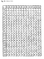
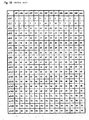
- Prime number sequence q[i] has been shown in Equation (3) and Figs. 1A, 1B. Also, the present applicant has already filed a method of efficiently calculating base sequence s[j] (Japanese Patent Application No. 2003-298493). For inter-row permutation pattern T[i], there are four fixed patterns, any one of which is selected.
- intra-row permutation pattern U[i][j] is calculated using prime number p, base sequence s[j], inter-row permutation pattern T[i], and prime number sequence q[i].
- prime number p, base sequence s[j], inter-row permutation pattern T[i], and prime number sequence q[i] are determined from the data length of data to be transmitted. Assume for example that p, s[j], T[i], q[i] have been determined as follows:
- intermediate value y[i] is calculated as follows based on Equation (4), p , q[i].
- Fig. 2 shows a flow chart of the procedure to find y[i].
- x[i][1] is calculated as follows based on y[i] calculated in Calculation Process 1, T[i], and Equations (4), (5):
- x[i][j] is calculated based on x[i][1] calculated in Calculation Process 2 and prime number p with reference to Equation (1), without performing a remainder calculation, as follows:
- the present invention relies only on addition and subtraction, instead of a remainder calculation, in calculating y[i] in Calculation Process 1. Specifically, the following calculations are made.
- z[i] floor (q[i]/(p-1) where floor (q[i]/(p-1)) is the quotient of q[i]/(p-1) the following inequalities are established: z[i] * (p-1) ⁇ q[i] ⁇ (z[i] + 1) * (q - 1) z[i] * (p-1) ⁇ q[i] ⁇ [i + 1] ⁇ q [i] + p - 1 ⁇ (z[l] + 2) * (p - 1)
- z[i] is represented by:
- the present invention makes it possible to reduce the operating time of a processor because of no need of the remainder calculation, which requires a large number of clocks to calculate y[i].
- the reduction in the operating time of the processor can lead to saving power consumed by the processor.
- the elimination of the remainder calculator in turn allows the circuit size of the apparatus to be reduced, as compared with an apparatus which includes the remainder calculator.
- the reduction in the circuit scale of the apparatus can in turn contribute to a reduction in the power consumed by the apparatus.
- z[i] is calculated based on Equation (8), prime number sequence q[i], and prime number p.
- the calculated result matches the result derived by Calculation Process 1 in Description of the Related Art.
- U[i][j] is determined by performing completely the same calculations in Calculation Process 2 to Calculation Process 4 in Description of the Related Art. No remainder calculation is included in Calculation Process 2 to Calculation Process 4.
- Interleave parameter processing apparatus 1 comprises processor 11, q[i] memory 12, and [i] memory 14.
- Interleave parameter processing apparatus 1 and interleaver 2 may be mounted in a mobile telephone and the like.
- Interleave parameter processing apparatus 1 receives data to be transmitted, and determines the data length of the data. Processor 11 calculates prime number p, s[j], T[i], q[i], then intermediate value y[i], and U[i][j] from the determined data length. Processor 11 stores calculated q[i] and y[i] in q[i] memory 12 and y[i] memory 14, respectively. Then, interleave parameter processing apparatus 1 outputs U[i][j] and T[i] to interleaver 2.
- Interleaver 2 receives data to be transmitted, encodes the data based on U[i][j] and T[i] received from interleave parameter processing apparatus 1, and outputs the encoded data.
- FIG. 4 there is illustrated a flow chart which represents a routine for calculating y[i] among calculations performed by processor 11 according to the present invention, described above.
- processor 11 initializes index i and variable div to zero, variable div corresponding to z[i].
- processor 11 makes a determination corresponding to Equation (8).
- q[i] ⁇ div+p-1 p-1 is added to the value of div at step 34.
- q[i] ⁇ div+p-1 the routine proceeds to step 35 without further processing.
- processor 11 increments i, and iterates the processing from step 33 to step 36 until i equals to R at step 37.
- steps 33, 37 since a conditional branch (steps 33, 37) takes two clocks, and other processing (steps 34, 35, 36) takes one clock, seven clocks are required for each iteration from step 33 to step 37.
- the prior art method requires 19 clocks for each iteration, the reduction of 12 clocks of the processing is achieved. Since R has the maximum value of 20, up to 240 clocks of the processing can be reduced.
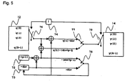
- FIG. 5 there is illustrated an exemplary implementation of interleave parameter processing apparatus 1.
- Memory 12 stores values of q[i]. Constant block 72 has the value of -(p-1). Register 73 has the value of -div. Register 74 generates a memory address. Memory 14 stores values of y[i]. Selector 76 selects the value of address i in memory 12. Selector 77 selects an output in accordance with the value of q[i]-div or q[i]-(div+p-1). Selector 78 selects an output in accordance with the value of -(div+p-1) or -div. Selector 79 selects a location in memory 14 in which data is to be stored.
- interleave parameter processing apparatus 1 In this exemplary implementation, counter 74 and register 73 hold therein zero as the value of i and div, respectively.
- Selector 76 selects data q[i] at address i in memory 12.
- q[i]-(div+p-1) is calculated with value -div in register 73 and value -(p-1) in constant block 72.
- selectors 77, 78 select q[i]-div, -div, respectively, and otherwise select q[i]-(div+p-1), -(div+p-1), respectively.
- interleave parameter processing apparatus 1 may be implemented by recording a program for embodying its functions on a computer readable recording medium, and loading the program recorded on the recording medium into a computer which should act as interleave parameter processing apparatus 1 so that the computer executes the program.
- the computer readable recording medium refers to a recording medium such as a flexible disk, a magneto-optical disk, a CD-ROM and the like, and a storage device such as a hard disk drive contained in a computer system, and the like.
- the computer readable recording medium also includes one which dynamically holds a program for a short period of time. (a transmission medium or a transmission wave) as is the case with the transmission of a program through the Internet, and one which holds a program for a certain period of time, such as a volatile memory within a computer system.
Landscapes
- Engineering & Computer Science (AREA)
- Computer Networks & Wireless Communication (AREA)
- Signal Processing (AREA)
- Error Detection And Correction (AREA)
Abstract
Description
- The present invention relates to an internal interleaver for turbo coding, referred to as a prime number interleaver, which has been normalized in wideband DS-CDMA (W-CDMA) that has been standardized as one of radio access networks (RAN) for a third-generation mobile communication system (IMT2000).
- Wideband DS-CDMA (W-CDMA) has been standardized as one of radio access networks (RAN) for the third-generation mobile communication system (IMT2000), and a turbo code internal interleaver, referred to as the "prime number interleaver," has been normalized in the standard. Detailed description thereof is disclosed in "3rd Generation Partnership Project; Technical Specification Group Radio Access Network; Multiplexing And Channel Coding (FDD)" (Release 1999), 3GPP TS25. 213 V3.10.0 (2002-06), Section 4.2.3.2.3, Turbo Code Internal lnterleaver, pp.16-19. The following description is based on this document.
- In an interleaver for the turbo code normalized in Standard 3GPP TS25.212 of IMT2000 (W-CDMA), intra-row permutation pattern U[i][j], which is indispensable for encoding data to be transmitted, is defined as follows using r[i] which is defined later:
- Herein, r[i] is defined as follows using inter-row permutation pattern T[i], and prime number sequence q[i] which is defined later:
- Prime number sequence q[i] is defined as follows using the number of rows R and prime number p of the interleaver:
- Referring to Figs. 1 A and 1 B, values for prime number sequence q[i] are exemplified for each value of prime number p when the number of rows R in the interleaver is equal to 20 (R=20).
- As described above, intra-row permutation pattern U[i][j] is calculated using prime number p, base sequence s[j], inter-row permutation pattern T[i], and prime number sequence q[i].
- In a mobile telephone and the like in IMT2000, a data length is first calculated for data to be transmitted. Then, prime number p, base sequence s[j], inter-row permutation pattern T[i], and prime number sequence q[i] are determined based on the calculated data length (or the size of a matrix for storing the data to be transmitted). Then, intra-row permutation pattern U[i][j] is calculated based on these values. Next, transmission data is encoded based on the calculated intra-row permutation pattern U[i][j] and inter-row permutation pattern T[i], and the encoded transmission data is transmitted to a mobile telephone network. Another mobile telephone which has received the encoded data, decodes the received encoded data based on intra-row permutation pattern U[i][j] and inter-row permutation pattern T[i] which have been calculated in a similar manner.
- Prime number p, base sequence s[j], and prime number sequence q[i] can be uniquely determined from the length of data to be transmitted (or the size of a matrix which stores the data to be transmitted). Prime number sequence q[i] has been shown in Equation (3) and Figs. 1A, 1B. Also, the present applicant has already filed a method of efficiently calculating base sequence s[j] (Japanese Patent Application No. 2003-298493). For inter-row permutation pattern T[i], there are four fixed patterns, any one of which is selected.
- As described above, intra-row permutation pattern U[i][j] is calculated using prime number p, base sequence s[j], inter-row permutation pattern T[i], and prime number sequence q[i]. However, for simplifying the calculation, intra-row permutation pattern U[i][j] is typically calculated after y[i], defined as follows, is determined as an intermediate value to calculate intra-row permutation pattern U[i][j]:
- In the following, description will be made of a method of calculating intra-row permutation pattern U[i][j] according to the prior art, using a specific example.
- First, prime number p, base sequence s[j], inter-row permutation pattern T[i], and prime number sequence q[i] are determined from the data length of data to be transmitted. Assume for example that p, s[j], T[i], q[i] have been determined as follows:
- Setting Parameters
- p=7
- s[i] = [1, 3, 2, 6, 4, 5] (j=0-5)
- T[i] = [4, 3, 2, 1, 0] (i=0-4) (R=5)
- q[i] = [1, 7, 11, 13, 17] (i=0-4) (R=5)
-
- First, intermediate value y[i] is calculated as follows based on Equation (4), p, q[i]. Fig. 2 shows a flow chart of the procedure to find y[i].
-
Calculation Process 1 - y[0] = q[0] * mod (7-1) = 1 * mod6 = 1
- y[1] = q[1] * mod (7-1) = 7 * mod6 = 1
- y[2] = q[2] * mod (7-1) = 11 * mod6 = 5
- y[3] = q[3] * mod (7-1) = 13 * mod6 = 1
- y[4] = q[4] * mod (7-1) = 17 * mod6 = 5
-
- Next, x[i][1] is calculated as follows based on y[i] calculated in
Calculation Process 1, T[i], and Equations (4), (5): -
Calculation Process 2 - y[i] = w[i][1] = x[T[i]][1]
- y[0] = w[0][1] = [T[0]][1] = x[4][1] = 1
- y[1] = w[1][1] = [T[1]][1] = x[3][1] = 1
- y[2] = w[2][1] = [T[2]][1] = x[2][1] = 5
- y[3] = w[3][1] = [T[3]][1] = x[1][1] = 1
- y[4] = w[4][1] = [T[4]][1] = x[0][1] = 5 Therefore, x[l][1] = [5, 1, 5, 1, 1] (I = 0 to 4) (R = 5)
-
- Next, x[i][j] is calculated based on x[i][1] calculated in
Calculation Process 2 and prime number p with reference to Equation (1), without performing a remainder calculation, as follows: -
Calculation Process 3 - x[0][0] = 0
- x[0][1] = 5
- x[0][2] = x[0][1] + x[0][1] - (p-1) = 5 + 5 - 6 = 4
- x[0][3] = x[0][2] + x[0][1] - (p-1) = 4 + 5 - 6 = 3
- x[0][4] = x[0][3] + x[0][1] - (p-1) = 3 + 5 - 6 = 2
- x[0][5] = x[0][4] + x[0][1] - (p-1) = 2 + 5 - 6 = 1
-
- (Since each of x[0][1]+x[0][1], x[0][2]+x[0][1], x[0][3]+x[0][1], x[0][4]+x[0][1] is larger than p-1, p-1 is subtracted from the value.)
- x[1][0] = 0
- x[1][1] = 1
- x[1][2] = x[1][1] + x[1][1] = 1 +1 = 2
- x[1][3] = x[1][2] + x[1][1] = 2 + 1 = 3
- x[1][4] = x[1][3] + x[1][1] = 3 + 1 = 4
- x[1][5] = x[1][4] + x[1][1] = 4 + 1 = 5
-
- (Since each of x[0][1]+x[0][1], x[0][2]+x[0][1], x[0][3]+x[0][1], x[0][4]+x[0][1] is smaller than p-1, the value is output as is.)
- x[2][0] = 0
- x[2][1] = 5
- x[2][2] = x[2][1] + x[2][1] - (p-1) = 5 + 5 - 6 = 4
- x[2][3] = x[2][2] + x[2][1] - (p-1) = 4 + 5 - 6 = 3
- x[2][4] = x[2][3] + x[2][1] - (p-1) = 3 + 5 - 6 = 2
- x[2][5] = x[2][4] + x[2][1] - (p-1) = 2 + 5 - 6 = 1
-
- (Since each of x[0][1]+x[0][1], x[0][2]+x[0][1], x[0][3]+x[0][1], x[0][4]+x[0][1] is larger than p-1, p-1 is subtracted from the value.)
- x[3][0] = 0
- x[3][1] = 1
- x[3][2] = x[3][1] + x[3][1] = 1 + 1 = 2
- x[3][3] = x[3][2] + x[3][1] = 2 + 1 = 3
- x[3][4] = x[3][3] + x[3][1] = 3 + 1 = 4
- x[3][5] = x[3][4] + x[3][1] = 4 + 1 = 5
-
- (Since each of x[0][1]+x[0][1], x[0][2]+x[0][1], x[0][3]+x[0][1], x[0][4]+x[0][1] is smaller than p-1, the value is output as is.)
- x[4][0] = 0
- x[4][1] = 5
- x[4][2] = x[4][1] + x[4][1] - (p-1) = 5 + 5 - 6 = 4
- x[4][3] = x[4][2] + x[4][1] - (p-1) = 4 + 5 - 6 = 3
- x[4][4] = x[4][3] + x[4][1] - (p-1) = 3 + 5 - 6 = 2
- x[4][5] = x[4][4] + x[4][1] - (p-1) = 2 + 5 - 6 = 1
-
- (Since each of x[0][1]+x[0][1], x[0][2]+x[0][1], x[0][3]+x[0][1], x[0][4]+x[0][1] is larger than p-1, p-1 is subtracted from the value.)
- Finally, U[i][j] is calculated based on x[i][j], s[i], and Equation (1).
-
Calculation Process 4 - U[0][0] = s[x[0][0]] = s[0] = 1
- U[0][1] = s[x[0][1]] = s[5] = 5
- U[0][2] = s[x[0][2]] = s[4] = 4
- U[0][3] = s[x[0][3]] = s[3] = 6
- U[0][4] = s[x[0][4]] = s[2] = 2
- U[0][5] = s[x[0][5]] = s[1] = 3
- U[1][0] = s[x[1][0]] = s[0] = 1
- U[1][1] = s[x[1][1]] = s[1] = 3
- U[1][2] = s[x[1][2]] = s[2] = 2
- U[1][3] = s[x[1][3]] = s[3] = 6
- U[1][4] = s[x[1][4]] = s[4] = 4
- U[1][5] = s[x[1][5]] = s[5] = 5
- U[2][0] = s[x[2][0]] = s[0] = 1
- U[2][1] = s[x[2][1]] = s[5] = 5
- U[2][2] = s[x[2][2]] = s[4] = 4
- U[2][3] = s[x[2][3]] = s[3] = 6
- U[2][4] = s[x[2][4]] = s[2] = 2
- U[2][5] = s[x[2][5]] = s[1] = 3
- U[3][0] = s[x[3][0]] = s[0] = 1
- U[3][1] = s[x[3][1]] = s[1] = 3
- U[3][2] = s[x[3][2]] = s[2] = 2
- U[3][3] = s[x[3][3]] = s[3] = 6
- U[3][4] = s[x[3][4]] = s[4] = 4
- U[3][5] = s[x[3][5]] = s[5] = 5
- U[4][0] = s[x[4][0]] = s[0] = 1
- U[4][1] = s[x[4][1]] = s[5] = 5
- U[4][2] = s[x[4][2]] = s[4] = 4
- U[4][3] = s[x[4][3]] = s[3] = 6
- U[4][4] = s[x[4][4]] = s[2] = 2
- U[4][5] = s[x[4][5]] = s[1] = 3
-
- In processors used in mobile telephones and the like, limitations in their circuit size often force them to perform the remainder calculations digit by digit. When a processor has a data width of 16 bits, 16 clocks are required for the calculation of each row of y[i] (
step 43 in Fig. 2) inCalculation Process 1. Further, assuming that two clocks are required for a conditional branch (step 45) in Fig. 2, and one clock is required for other processing (step 44) in Fig. 2, 19 clocks are required for each execution ofstep 43 to step 45 in Fig. 2. As a result,Calculation Process 1 requires a total of 19 * R clocks (since the maximum value of R is 20, 380 clocks are required at maximum). - It is an object of the present invention to significantly reduce the number of clocks required to calculate y[i] in
Calculation Process 1 to save the processing time ofCalculation Process 1. - To achieve the above object, the present invention relies only on addition and subtraction, instead of a remainder calculation, in calculating y[i] in
Calculation Process 1. Specifically, the following calculations are made. - As can been seen from Figs. 1A, 1 B, q[i+1]-q[i]<p-1 stands for all prime numbers p, so that when z[i] is defined as follows:
the following inequalities are established: - z[0]=0;
- z[i]=z[i-1] when q[i]<z[i-1]+p-1; and
- z[i]=z[i-1]+p-1 when q[i]≥z[i-1]+p-1,
-
- As described above, the present invention makes it possible to reduce the operating time of a processor because of no need of the remainder calculation, which requires a large number of clocks to calculate y[i]. The reduction in the operating time of the processor can lead to saving power consumed by the processor. Further, the elimination of the remainder calculator in turn allows the circuit size of the apparatus to be reduced, as compared with an apparatus which includes the remainder calculator. The reduction in the circuit scale of the apparatus can in turn contribute to a reduction in the power consumed by the apparatus.
- The above and other objects, features and advantages of the present invention will become apparent from the following description with reference to the accompanying drawings which illustrate examples of the present invention.
-
- Figs. 1A, 1 B are tables exemplifying values of prime number sequence p[i] for each value of prime number p when an interleaver has the number of rows R equal to 20 (R=20);
- Fig. 2 is a flow chart illustrating a procedure for calculating y[i] according to the prior art;
- Fig. 3 is a block diagram illustrating the configuration of one embodiment of the present invention;
- Fig. 4 is a flow chart illustrating a procedure for calculating y[i] according to the present invention; and
- Fig. 5 is a diagram illustrating an exemplary implementation of an interleave parameter processing apparatus.
-
- While a method of calculating y[i] according to the present invention is performed as described in SUMMARY OF THE INVENTION, the following description will be made using a specific example.
- Again, set parameters used herein are the same as those used in Description of the Related Art. The calculation of y[i] corresponding to
Calculation Process 1 in Description of the Related Art is made based on the set parameters, Equation (8), and Equation (9). - First, z[i] is calculated based on Equation (8), prime number sequence q[i], and prime number p.
- Calculation of z[i]
- z[0] = 0
- Since 7=q[1]≥z[0]+p-1=6, z[1]=z[0]+p-1 = 6
- Since 11=q[2]<z[1]+p-1=12, z[2]=z[1] = 6
- Since 13=q[3]≥z[2]+p-1=12, z[3]=z[2]+p-1=12
- Since 17=q[4]<z[3]+p-1=18, z[4]=z[3] =12
-
- Next, y[i] is calculated based on z[i] and q[i] determined during the calculation of z[i], and Equation (9):
- Calculation of y[i]
- y[0] = q[0] - z[0] = 1 - 0 = 1
- y[1] = q[1] - z[1] = 7 - 6 = 1
- y[2] = q[2] - z[2] = 11 - 6 = 5
- y[3] = q[3] - z[3] = 13 - 12 = 1
- y[4] = q[4] - z[4] = 17 - 12 = 5
-
- The calculated result matches the result derived by
Calculation Process 1 in Description of the Related Art. - Subsequently, U[i][j] is determined by performing completely the same calculations in
Calculation Process 2 toCalculation Process 4 in Description of the Related Art. No remainder calculation is included inCalculation Process 2 toCalculation Process 4. - In the following, a detailed description will be made of an interleave parameter processing apparatus which employs the foregoing method of calculating y[i].
- Referring to Fig. 3, there is illustrated a configuration of the interleave parameter processing apparatus according to an embodiment of the present invention. Interleave
parameter processing apparatus 1 comprisesprocessor 11, q[i]memory 12, and [i]memory 14. Interleaveparameter processing apparatus 1 andinterleaver 2 may be mounted in a mobile telephone and the like. - Interleave
parameter processing apparatus 1 receives data to be transmitted, and determines the data length of the data.Processor 11 calculates prime number p, s[j], T[i], q[i], then intermediate value y[i], and U[i][j] from the determined data length.Processor 11 stores calculated q[i] and y[i] in q[i]memory 12 and y[i]memory 14, respectively. Then, interleaveparameter processing apparatus 1 outputs U[i][j] and T[i] tointerleaver 2. -
Interleaver 2 receives data to be transmitted, encodes the data based on U[i][j] and T[i] received from interleaveparameter processing apparatus 1, and outputs the encoded data. - Referring to Fig. 4, there is illustrated a flow chart which represents a routine for calculating y[i] among calculations performed by
processor 11 according to the present invention, described above. - At
step 32,processor 11 initializes index i and variable div to zero, variable div corresponding to z[i]. Atstep 33,processor 11 makes a determination corresponding to Equation (8). When q[i]≥div+p-1, p-1 is added to the value of div atstep 34. When q[i]<div+p-1, the routine proceeds to step 35 without further processing. Atstep 35,processor 11 calculates y[i] from y[i]=q[i]-div. Atstep 36,processor 11 increments i, and iterates the processing fromstep 33 to step 36 until i equals to R atstep 37. - Here, since a conditional branch (steps 33, 37) takes two clocks, and other processing (
steps step 33 to step 37. As discussed in Description of the Related Art, the prior art method requires 19 clocks for each iteration, the reduction of 12 clocks of the processing is achieved. Since R has the maximum value of 20, up to 240 clocks of the processing can be reduced. - Referring to Fig. 5, there is illustrated an exemplary implementation of interleave
parameter processing apparatus 1. -
Memory 12 stores values of q[i].Constant block 72 has the value of -(p-1).Register 73 has the value of -div.Register 74 generates a memory address.Memory 14 stores values of y[i].Selector 76 selects the value of address i inmemory 12.Selector 77 selects an output in accordance with the value of q[i]-div or q[i]-(div+p-1).Selector 78 selects an output in accordance with the value of -(div+p-1) or -div.Selector 79 selects a location inmemory 14 in which data is to be stored. - Next, a description will be made of the operation of interleave
parameter processing apparatus 1 in this exemplary implementation. Initially, counter 74 and register 73 hold therein zero as the value of i and div, respectively.Selector 76 selects data q[i] at address i inmemory 12. q[i]-(div+p-1) is calculated with value -div inregister 73 and value -(p-1) inconstant block 72. When q[i]-(div+p-1)<0,selectors selector 77 is stored inmemory 14 at address i, while the value selected byselector 78 is stored inregister 73. The foregoing processing is repeated until value i in counter 74 equals to R-1. With the above processing, y[i] is generated inmemory 14. - Other than an implementation by dedicated hardware, interleave
parameter processing apparatus 1 may be implemented by recording a program for embodying its functions on a computer readable recording medium, and loading the program recorded on the recording medium into a computer which should act as interleaveparameter processing apparatus 1 so that the computer executes the program. The computer readable recording medium refers to a recording medium such as a flexible disk, a magneto-optical disk, a CD-ROM and the like, and a storage device such as a hard disk drive contained in a computer system, and the like. Further, the computer readable recording medium also includes one which dynamically holds a program for a short period of time. (a transmission medium or a transmission wave) as is the case with the transmission of a program through the Internet, and one which holds a program for a certain period of time, such as a volatile memory within a computer system. - While preferred embodiments of the present invention have been described using specific terms, such description is for illustrative purposes only, and it is to be understood that changes and variations may be made without departing from the spirit or scope of the following claims.
Claims (4)
- In an interleave parameter processing apparatus configured to supply an interleaver for a turbo code defined by 3GPP TS25.212 which is a standard of IMT2000 with an intra-row permutation pattern U[i][j] and an inter-row permutation pattern T[i] required by said interleaver for encoding data to be transmitted, an interleave parameter processing method for calculating y[i]=q[i]xmod(p-1) which should be determined as an intermediate value in a process in which said interleave parameter processing apparatus calculates the intra-row permutation pattern U[i][j] based on the inter-row permutation pattern T[i], a prime number p, a base sequence s[j], and a prime number sequence q[i] determined from the length of the transmission data, said method comprising the steps of:a) initializing an index i and a variable div to zero;b) adding p-1 to the value of div and storing the resulting value when q[i]≥div+p-1, and storing the value of div as is when q[i]<div+p-1;c) calculating y[i] in accordance with y[i]=q[i]-div based on the value of div stored at step b); andd) incrementing i until i equals to the number R of rows of said interleaver to repeat step b) and step c) to calculate y[i] for all i.
- An interleave parameter processing apparatus for supplying an intra-row permutation pattern U[i][j] and an inter-row permutation pattern T[i] to an interleaver for a turbo code defined by 3GPP TS25.212 which is a standard of IMT2000, said interleave parameter processing apparatus configured to calculate y[i]=q[i]xmod(p-1) which should be determinedas an intermediate value in a process of calculating the intra-row permutation pattern U[i][j] based on the inter-row permutation pattern T[i], a prime number p, a base sequence s[j], and a prime number sequence q[i] found from the length of the transmission data, said apparatus comprising:means for initializing an index i and a variable div to zero;means for adding p-1 to the value of div and storing the resulting value when q[i]≥div+p-1, and storing the value of div as is when q[i]<div+p-1;means for calculating y[i] from y[i]=q[i]-div based on the value of div stored by said adding means; andmeans for incrementing i until i equals to the number R of rows of said interleaver, and causing said adding means and said calculating means to repeat the associated processing to calculate y[i] for all i.
- A mobile telephone comprising the interleave parameter processing apparatus according to claim 2.
- In an interleave parameter processing apparatus configured to supply an interleaver for a turbo code defined by 3GPP TS25.212 which is a standard of IMT2000 with an intra-row permutation pattern U[i][j] and an inter-row permutation pattern T[i] required by said interleaver for encoding data to be transmitted, a computer program for enabling a computer to calculate y[i]=q[i]xmod(p-1) which should be determined as an intermediate value in a process in which said interleave parameter processing apparatus calculates the intra-row permutation pattern U[i][j] based on the inter-row permutation pattern T[i], a prime number p, a base sequence s[j], and a prime number sequence q[i] determined from the length of the transmission data, said program comprising:a first set of instructions for initializing an index i and a variable div to zero;a second set of instructions for adding p-1 to the value of div and storing the resulting value when q[i]≥div+p-1, and storing the value of div as is when q[i]<div+p-1;a third set of instructions for calculating y[i] in accordance with y[i]=q[i]-div based on the value of div stored at step b); anda fourth set of instructions for incrementing i until i equals to the number R of rows of said interleaver to repeat the executions of said secound and third set of instructions to calculate y[i] for all i.
Applications Claiming Priority (2)
| Application Number | Priority Date | Filing Date | Title |
|---|---|---|---|
| JP2004053923 | 2004-02-27 | ||
| JP2004053923A JP4909498B2 (en) | 2004-02-27 | 2004-02-27 | Interleave parameter calculation method / program / program recording medium / device, mobile phone |
Publications (3)
| Publication Number | Publication Date |
|---|---|
| EP1569374A2 true EP1569374A2 (en) | 2005-08-31 |
| EP1569374A3 EP1569374A3 (en) | 2012-03-07 |
| EP1569374B1 EP1569374B1 (en) | 2013-08-14 |
Family
ID=34747548
Family Applications (1)
| Application Number | Title | Priority Date | Filing Date |
|---|---|---|---|
| EP20050004021 Expired - Lifetime EP1569374B1 (en) | 2004-02-27 | 2005-02-24 | Interleave parameter processing method |
Country Status (4)
| Country | Link |
|---|---|
| US (1) | US7698620B2 (en) |
| EP (1) | EP1569374B1 (en) |
| JP (1) | JP4909498B2 (en) |
| CN (1) | CN100449949C (en) |
Cited By (1)
| Publication number | Priority date | Publication date | Assignee | Title |
|---|---|---|---|---|
| US20120163211A1 (en) * | 2010-12-23 | 2012-06-28 | Electronics And Telecommunications Research Institute | Data rate matching method and apparatus for use in mobile communication systems |
Families Citing this family (6)
| Publication number | Priority date | Publication date | Assignee | Title |
|---|---|---|---|---|
| KR100708474B1 (en) * | 2005-09-15 | 2007-04-18 | 삼성전자주식회사 | Parameter Determination Method of Linear Joint Interleaver and Linear Joint Interleaver |
| CN101453220B (en) * | 2007-12-03 | 2012-02-01 | 华为技术有限公司 | Weaving and coding method for duplicate accumulation code encoding, corresponding equipment |
| US8693570B2 (en) * | 2008-10-31 | 2014-04-08 | Industrial Technology Research Institute | Communication methods and systems having data permutation |
| JP2013523043A (en) | 2010-03-22 | 2013-06-13 | エルアールディシー システムズ、エルエルシー | How to identify and protect the integrity of a source dataset |
| US9015551B2 (en) * | 2012-04-19 | 2015-04-21 | Mediatek Inc. | Decoding apparatus with de-interleaving efforts distributed to different decoding phases and related decoding method thereof |
| CN109842461B (en) * | 2017-11-24 | 2022-08-26 | 山东协力合智通信科技有限公司 | Data interleaving method and device, and interleaved data de-interleaving method and device |
Family Cites Families (10)
| Publication number | Priority date | Publication date | Assignee | Title |
|---|---|---|---|---|
| AU752231B2 (en) | 1999-05-19 | 2002-09-12 | Samsung Electronics Co., Ltd. | Turbo interleaving apparatus and method |
| JP3865556B2 (en) | 2000-02-01 | 2007-01-10 | 松下電器産業株式会社 | Sample data conversion apparatus and program recording medium |
| JP3399904B2 (en) * | 2000-03-17 | 2003-04-28 | 松下電器産業株式会社 | Interleave address generator |
| FR2809249B1 (en) | 2000-05-16 | 2004-04-23 | France Telecom | METHOD AND SYSTEM FOR ITERATIVE DETECTION AND DECODING OF RECEIVED SYMBOLS, COUPLED TO A REESTIMATION OF THE TRANSMISSION CHANNEL COEFFICIENTS |
| US6675347B1 (en) * | 2000-07-19 | 2004-01-06 | Qualcomm, Incorporated | Method and apparatus for combined puncturing and repeating of code symbols in a communications system |
| KR100393608B1 (en) * | 2000-09-29 | 2003-08-09 | 삼성전자주식회사 | An internal interleaver of the turbo decoder in an umts system and method for interleaving thereof |
| US6845482B2 (en) * | 2001-02-28 | 2005-01-18 | Qualcomm Incorporated | Interleaver for turbo decoder |
| RU2004117073A (en) * | 2001-11-05 | 2005-03-27 | Нокиа Корпорейшн (Fi) | PARTIALLY FILLED BLOCK INTERIOR FOR COMMUNICATION SYSTEM |
| US7058874B2 (en) * | 2002-05-24 | 2006-06-06 | Lucent Technologies Inc. | Interleaver address generator and method of generating an interleaver address |
| JP4265345B2 (en) * | 2003-08-22 | 2009-05-20 | 日本電気株式会社 | Mobile phone, interleave parameter calculation device, method and program |
-
2004
- 2004-02-27 JP JP2004053923A patent/JP4909498B2/en not_active Expired - Fee Related
-
2005
- 2005-02-24 US US11/064,479 patent/US7698620B2/en not_active Expired - Fee Related
- 2005-02-24 EP EP20050004021 patent/EP1569374B1/en not_active Expired - Lifetime
- 2005-02-28 CN CNB2005100524559A patent/CN100449949C/en not_active Expired - Fee Related
Non-Patent Citations (1)
| Title |
|---|
| None |
Cited By (2)
| Publication number | Priority date | Publication date | Assignee | Title |
|---|---|---|---|---|
| US20120163211A1 (en) * | 2010-12-23 | 2012-06-28 | Electronics And Telecommunications Research Institute | Data rate matching method and apparatus for use in mobile communication systems |
| US8792375B2 (en) * | 2010-12-23 | 2014-07-29 | Electronics And Telecommunications Research Institute | Data rate matching method and apparatus for use in mobile communication systems |
Also Published As
| Publication number | Publication date |
|---|---|
| JP4909498B2 (en) | 2012-04-04 |
| EP1569374A3 (en) | 2012-03-07 |
| CN100449949C (en) | 2009-01-07 |
| CN1661925A (en) | 2005-08-31 |
| EP1569374B1 (en) | 2013-08-14 |
| US20050204259A1 (en) | 2005-09-15 |
| JP2005244770A (en) | 2005-09-08 |
| US7698620B2 (en) | 2010-04-13 |
Similar Documents
| Publication | Publication Date | Title |
|---|---|---|
| FI107094B (en) | Procedure for updating linear feedback shift register in a code generator | |
| US7155642B2 (en) | Interleaver for a turbo encoder in an UMTS and method for performing interleaving | |
| US6667708B2 (en) | Method and system for a programmable code generator | |
| US7363574B1 (en) | Method and system for parallel CRC calculation | |
| JP2001517897A (en) | Method and apparatus for generating a cryptographic decryption key | |
| US20120076294A1 (en) | Arithmetic method and apparatus for supporting aes and aria encryption/decryption functions | |
| EP1569374A2 (en) | Interleave parameter processing method | |
| KR20120130267A (en) | Efficient diffusion dithering using dyadic rationals | |
| Lee et al. | Software defined radio–a high performance embedded challenge | |
| KR20020019451A (en) | Method for operating rate match and rate match device | |
| EP1411643B1 (en) | A method and apparatus for generating an interleaved address | |
| US20100077187A1 (en) | System and Method to Execute a Linear Feedback-Shift Instruction | |
| US7415263B2 (en) | Receiver for a wireless communication device | |
| US20030002666A1 (en) | Method and apparatus for creating a message digest using a parallel, one-way hash algorithm | |
| US7318184B2 (en) | Mobile telephone, apparatus, method, and program for calculating an interleave parameter | |
| US6947491B2 (en) | Third generation FDD modem interleaver | |
| US20100104098A1 (en) | Cryptographic method and device for scheduling and compressing message based on secure hash algorithm | |
| US8417756B2 (en) | Method and apparatus for efficient modulo multiplication | |
| JP3943329B2 (en) | Rate matching / dematching processor | |
| WO2008151981A2 (en) | Rate matching device and method thereof, de-rate matching device and method thereof | |
| US7437650B2 (en) | Pre-emptive interleaver address generator for turbo decoders | |
| CN1845482B (en) | Downlink channel code perforating compression device and realization method for broadband CDMA system | |
| US8200733B1 (en) | Device having interleaving capabilities and a method for applying an interleaving function | |
| JP2003046410A (en) | Digital matched filter and mobile radio terminal employing the same | |
| Darbel et al. | A UMTS-FDD cell search engine |
Legal Events
| Date | Code | Title | Description |
|---|---|---|---|
| PUAI | Public reference made under article 153(3) epc to a published international application that has entered the european phase |
Free format text: ORIGINAL CODE: 0009012 |
|
| AK | Designated contracting states |
Kind code of ref document: A2 Designated state(s): AT BE BG CH CY CZ DE DK EE ES FI FR GB GR HU IE IS IT LI LT LU MC NL PL PT RO SE SI SK TR |
|
| AX | Request for extension of the european patent |
Extension state: AL BA HR LV MK YU |
|
| PUAL | Search report despatched |
Free format text: ORIGINAL CODE: 0009013 |
|
| AK | Designated contracting states |
Kind code of ref document: A3 Designated state(s): AT BE BG CH CY CZ DE DK EE ES FI FR GB GR HU IE IS IT LI LT LU MC NL PL PT RO SE SI SK TR |
|
| AX | Request for extension of the european patent |
Extension state: AL BA HR LV MK YU |
|
| RIC1 | Information provided on ipc code assigned before grant |
Ipc: H04L 1/00 20060101AFI20120201BHEP |
|
| 17P | Request for examination filed |
Effective date: 20120215 |
|
| 17Q | First examination report despatched |
Effective date: 20120412 |
|
| AKX | Designation fees paid |
Designated state(s): DE FR GB IT |
|
| GRAP | Despatch of communication of intention to grant a patent |
Free format text: ORIGINAL CODE: EPIDOSNIGR1 |
|
| GRAS | Grant fee paid |
Free format text: ORIGINAL CODE: EPIDOSNIGR3 |
|
| GRAP | Despatch of communication of intention to grant a patent |
Free format text: ORIGINAL CODE: EPIDOSNIGR1 |
|
| GRAA | (expected) grant |
Free format text: ORIGINAL CODE: 0009210 |
|
| INTG | Intention to grant announced |
Effective date: 20130620 |
|
| AK | Designated contracting states |
Kind code of ref document: B1 Designated state(s): DE FR GB IT |
|
| REG | Reference to a national code |
Ref country code: GB Ref legal event code: FG4D |
|
| REG | Reference to a national code |
Ref country code: DE Ref legal event code: R096 Ref document number: 602005040811 Country of ref document: DE Effective date: 20131010 |
|
| PLBE | No opposition filed within time limit |
Free format text: ORIGINAL CODE: 0009261 |
|
| STAA | Information on the status of an ep patent application or granted ep patent |
Free format text: STATUS: NO OPPOSITION FILED WITHIN TIME LIMIT |
|
| 26N | No opposition filed |
Effective date: 20140515 |
|
| REG | Reference to a national code |
Ref country code: DE Ref legal event code: R097 Ref document number: 602005040811 Country of ref document: DE Effective date: 20140515 |
|
| REG | Reference to a national code |
Ref country code: GB Ref legal event code: 732E Free format text: REGISTERED BETWEEN 20141023 AND 20141029 |
|
| REG | Reference to a national code |
Ref country code: FR Ref legal event code: TP Owner name: LENOVO INNOVATIONS LIMITED (HONG KONG), HK Effective date: 20141119 |
|
| REG | Reference to a national code |
Ref country code: FR Ref legal event code: PLFP Year of fee payment: 12 |
|
| PGFP | Annual fee paid to national office [announced via postgrant information from national office to epo] |
Ref country code: IT Payment date: 20160222 Year of fee payment: 12 |
|
| PGFP | Annual fee paid to national office [announced via postgrant information from national office to epo] |
Ref country code: FR Payment date: 20160108 Year of fee payment: 12 |
|
| PGFP | Annual fee paid to national office [announced via postgrant information from national office to epo] |
Ref country code: DE Payment date: 20170221 Year of fee payment: 13 |
|
| PGFP | Annual fee paid to national office [announced via postgrant information from national office to epo] |
Ref country code: GB Payment date: 20170222 Year of fee payment: 13 |
|
| REG | Reference to a national code |
Ref country code: FR Ref legal event code: ST Effective date: 20171031 |
|
| PG25 | Lapsed in a contracting state [announced via postgrant information from national office to epo] |
Ref country code: FR Free format text: LAPSE BECAUSE OF NON-PAYMENT OF DUE FEES Effective date: 20170228 |
|
| PG25 | Lapsed in a contracting state [announced via postgrant information from national office to epo] |
Ref country code: IT Free format text: LAPSE BECAUSE OF NON-PAYMENT OF DUE FEES Effective date: 20170224 |
|
| REG | Reference to a national code |
Ref country code: DE Ref legal event code: R119 Ref document number: 602005040811 Country of ref document: DE |
|
| GBPC | Gb: european patent ceased through non-payment of renewal fee |
Effective date: 20180224 |
|
| PG25 | Lapsed in a contracting state [announced via postgrant information from national office to epo] |
Ref country code: DE Free format text: LAPSE BECAUSE OF NON-PAYMENT OF DUE FEES Effective date: 20180901 |
|
| PG25 | Lapsed in a contracting state [announced via postgrant information from national office to epo] |
Ref country code: GB Free format text: LAPSE BECAUSE OF NON-PAYMENT OF DUE FEES Effective date: 20180224 |