EP1569316B1 - Vorrichtung und Verfahren für gleichzeitiges Laden von mehreren Akkumulatoren - Google Patents
Vorrichtung und Verfahren für gleichzeitiges Laden von mehreren Akkumulatoren Download PDFInfo
- Publication number
- EP1569316B1 EP1569316B1 EP04251147A EP04251147A EP1569316B1 EP 1569316 B1 EP1569316 B1 EP 1569316B1 EP 04251147 A EP04251147 A EP 04251147A EP 04251147 A EP04251147 A EP 04251147A EP 1569316 B1 EP1569316 B1 EP 1569316B1
- Authority
- EP
- European Patent Office
- Prior art keywords
- battery
- charge
- charging
- charger
- rechargeable batteries
- Prior art date
- Legal status (The legal status is an assumption and is not a legal conclusion. Google has not performed a legal analysis and makes no representation as to the accuracy of the status listed.)
- Expired - Lifetime
Links
Images


Classifications
-
- H02J7/56—
Definitions
- the invention relates generally to chargers for rechargeable batteries of mobile electronic devices.
- embodiments of the invention relate to a method for simultaneously charging the battery inside a mobile electronic device and a second battery for the mobile electronic device.
- FR2841699 discloses a portable charger comprising a connection to an electric source, a plurality of connecting points of rechargeable portable appliances for different usage, and an adapter, tapping power supply at the electric source and adapting it to the recharging supply of the rechargeable portable appliances.
- the adapter includes a microprocessor and a multiple output converter delivering voltages and currents adapted to the appliances to be recharged.
- the adapter adapts the charge power to the portable appliance based on the charge programme for that appliance.
- the charger enables simultaneous recharge of different rechargeable appliances in a manner adapted to each appliance.
- the invention provides a method of charging two or more rechargeable batteries from a single current source by use of two or more separate charging ports, the batteries being coupled to different respective charging ports, wherein the method comprises: determining relative amounts of charge required to fully charge said two or more rechargeable batteries, and allocating charging currents from the single current source to the two or more separate charging ports based on said relative amounts of charge so that said two or more rechargeable batteries will become fully charged at substantially the same time.
- a charging current allocated to a particular charging port may be determined at least in part on an average current drain during usage of the rechargeable battery coupled to the particular charging port.
- the invention provides a charger for charging two or more rechargeable batteries, the charger comprising: a single current source; two or more separate charging ports, a current allocator for allocating charging currents from said single current source to said two or more ports; and a controller for determining relative amounts of charge required to fully charge two or more rechargeable batteries coupled to different respective ones of said two or more ports and for determining said charging currents to be allocated by said current allocator based on said determined relative amounts of charge so that said two or more rechargeable batteries will become fully charged at substantially the same time.
- the charger may include a measurement unit to measure voltage differences at the two or more charging ports for use in determining said charging currents.
- the charger may also include one or more lookup tables.
- the controller may determine from the one or more lookup tables an amount of charge required to fully charge a battery based on a measured voltage difference, a battery type, and an average current drain of the battery during usage.
- One of the two or more rechargeable batteries, in use of the charger may be inside a battery-operated device.
- the controller may receive a voltage of the one rechargeable battery from the battery-operated device for use in determining an amount of charge required to fully charge the one rechargeable battery.
- the charger may include one or more lookup tables, and the controller may determine from the one or more lookup tables an amount of charge required to fully charge a battery based on the received voltage for the one rechargeable battery, a battery type, and an average current drain of the battery during usage.
- FIG. 1 is simplified front view of a charger, a battery-operated device and a battery, in accordance with some embodiments of the invention.
- FIG. 2 is a simplified block diagram of a charger, a battery-operated device and a battery, in accordance with some embodiments of the invention
- FIG. 3 is a simplified block diagram of a charger and two batteries, in accordance with some embodiments of the invention.
- FIG. 4 is a flowchart of an exemplary method for simultaneously charging multiple rechargeable batteries, according to some embodiments of the invention.
- FIG. 1 is simplified front view of a charger 2, a battery-operated device 4 and a battery 6, in accordance with some embodiments of the invention.
- Charger 2 may have, for example, two charging ports 8 and 10.
- Battery-operated device 4 is coupled to charging port 8 and battery 6 is coupled to charging port 10.
- Charger 2 may be capable of simultaneously charging the battery of battery-operated device 4 and battery 6.
- charger 2 may have more than two charging ports, and may therefore be capable of simultaneously charging more than two batteries.
- a charger according to some embodiments of the invention may have five charging ports, and may be capable of simultaneously charging one, two, three, four or five batteries.
- FIG. 2 is a simplified block diagram of charger 2, battery-operated device 4 and battery 6, in accordance with some embodiments of the invention.
- Battery-operated device 4 may include a battery 5 and charging circuitry 7.
- Charger 2 may have, for example, two charging ports 8 and 10, having respective positive terminals 12 and 14, and respective negative terminals 16 and 18.
- a positive terminal 20 of battery 5 may be coupled to positive terminal 12 of charging port 8 via charging circuitry 7 and a negative terminal 22 of battery 5 may be coupled to negative terminal 16 of charging port 8 via charging circuitry 7.
- a positive terminal 24 of battery 6 may be coupled to positive terminal 14 of charging port 10 and a negative terminal 26 of battery 6 may be coupled to negative terminal 18 of charging port 10.
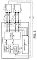
- FIG. 3 is a simplified block diagram of charger 2 and batteries 5 and 6 to be charged, in accordance with some embodiments of the invention. Many of the elements in FIG. 3 are the same as or similar to elements of FIG. 2 , and therefore the following description applies equally to FIG. 2 and FIG. 3 .
- Charger 2 may include a current source 28, a current allocator 30, a controller 32 and a measurement unit 34.
- Current source 28 may be capable of providing a current 36 of, for example, 500 milliamps (mA).
- Current allocator 30 may receive current 36, and may be capable of allocating a current portion 40 of current 36 to charging port 8 and a current portion 42 of current 36 to charging port 10.
- current portion 40 may be 140 mA and current portion 42 may be 360 mA.
- the allocation proportions of current 36 to current portions 40 and 42 may be controllable, at least in part, by controller 32 via control signals 38.
- controller 32 may optionally receive battery type identifications 45 and 46 from batteries 5 and 6, respectively.
- charging circuitry 7 may obtain the battery type identification from battery 5 and pass the information onwards to controller 32.
- Controller 32 may comprise one or more look up tables 48 containing information regarding one or more types of batteries. Such information may include, for example, the maximum charge capacity, the average current drain from the battery during usage, and the estimated relationship between the output voltage of the battery and the unused capacity of the battery.
- the type of batteries 5 and 6, and optionally the average current drain from batteries 5 and 6 during usage may be known in advance.
- mechanical constraints may mean that only one type of battery can be coupled to charging port 8 or to charging port 10.
- Measurement unit 34 may be capable of measuring the voltage difference between positive terminal 12 and negative terminal 16, and may be capable of measuring the voltage difference between positive terminal 14 and negative terminal 18.
- Measurement unit 34 may be controlled, at least in part, by controller 32. Controller 32 may command measurement unit 34 via signals 52 to measure the voltage difference between positive terminal 12 and negative terminal 16, and may receive the measurement result from measurement unit 34 via signals 54. In addition, controller 32 may command measurement unit 34 via signals 52 to measure the voltage difference between positive terminal 14 and negative terminal 18, and may receive the measurement result from measurement unit 34 via signals 54.
- battery-operated device 4 may report the actual voltage of battery 5 to controller 32 via a data path 55.
- Controller 32 may use look-up table 48 to determine the charge in the battery coupled to the charging port from the measurement of the voltage difference and the average current drain from the battery during usage.
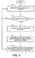
- FIG. 4 is a flowchart of an exemplary method for simultaneously charging multiple rechargeable batteries, according to some embodiments of the invention.
- the exemplary method of FIG. 4 may be executed by controller 32, although the invention is not limited in this respect.
- Controller 32 may check whether any batteries are coupled to charging ports 8 and 10 (100). If no battery is coupled to charging ports 8 and 10 (102), the method may continue to block 100. However, if at least one battery is coupled (to either charging port 8, charging port 10, or to both), controller 32 may determine the types of the coupled batteries (104). The difference between the maximum charge capacity and the charge in the battery is determined for each of the coupled batteries (106). For example, this difference is determined by measuring the battery's voltage and obtaining the corresponding information from look up tables 48 for the average current drain from the battery during usage.
- the charging current for each of the coupled batteries is set (e.g., current portions 40 and 42) so that all coupled batteries may become fully charged at substantially the same time (108).
- the method may repeat from block 100 in order to detect changes in the number and type of coupled batteries, and to adjust the charging currents accordingly, and to adjust the charging currents according to the progress of the charging process.
- the total available current (current 36) is 500 mA. Therefore, the sum of current portion 40 and current portion 42 may not exceed 500 mA.
- controller 32 may recheck the charge of the batteries from time to time so that current allocator 30 can readjust the charge allocation accordingly.
Landscapes
- Charge And Discharge Circuits For Batteries Or The Like (AREA)
- Secondary Cells (AREA)
Claims (24)
- Verfahren zum Aufladen von zwei oder mehreren wiederaufladbaren Akkumulatoren (5,6) aus einer einzigen Stromquelle (28) unter Benutzung von zwei oder mehreren getrennten Ladeanschlüssen (8,10), wobei die Akkumulatoren (5,6) an verschiedene entsprechende Ladeanschlüsse (8,10) angeschlossen sind,
umfassend:das Bestimmen relativer Auflademengen, die erforderlich sind, um die zwei oder mehreren wiederaufladbaren Akkumulatoren (5,6) vollständig aufzuladen, unddadurch gekennzeichnet, dass das Zuteilen von Aufladeströmen aus der einzigen Stromquelle (28) an die zwei oder mehreren getrennten Ladeanschlüsse (8,10) auf den relativen Auflademengen basiert, so dass die zwei oder mehreren wiederaufladbaren Akkumulatoren (5,6) im Wesentlichen gleichzeitig vollständig aufgeladen werden. - Verfahren nach Anspruch 1, wobei der Schritt des Bestimmens das Bestimmen der relativen Auflademengen, die zum vollständigen Aufladen der mindestens zwei oder mehreren wiederaufladbaren Akkumulatoren (5,6) erforderlich sind, auf der Basis eines Unterschied zwischen einer maximalen Aufladekapazität und einer Ladung in dem Akkumulator für jeden der zwei oder mehreren wiederaufladbaren Akkumulatoren (5,6) umfasst.
- Verfahren nach Anspruch 2, umfassend den Schritt des Bestimmens, für jeden der zwei oder mehreren wiederaufladbaren Akkumulatoren (5,6), der Ladung in dem Akkumulator durch Erhalten eines Spannungsunterschieds des Akkumulators und von Angaben über einen durchschnittlichen Stromverbrauch des Akkumulators während der Benutzung.
- Verfahren nach Anspruch 3, wobei der Schritt des Erhaltens eines Spannungsunterschieds für jeden der zwei oder mehreren wiederaufladbaren Akkumulatoren (5,6) das Messen des Spannungsunterschieds für jeden Akkumulator an seinem jeweiligen Ladeanschluss (8,10) umfasst.
- Verfahren nach Anspruch 3, wobei einer der zwei oder mehreren wiederaufladbaren Akkumulatoren (5) sich innerhalb einer akkumulatorbetriebenen Vorrichtung (4) befindet und das Verfahren das Empfangen eines Spannungsunterschieds des einen wiederaufladbaren Akkumulatoren (5) von der akkumulatorbetriebenen Vorrichtung (4) zur Anwendung beim Bestimmen der Ladung in dem Akkumulator (5) umfasst.
- Verfahren nach einem der Ansprüche 3 bis 5, wobei die Angaben über den durchschnittlichen Stromverbrauch des Akkumulators während der Benutzung aus einer Nachschlagtabelle (48) erhalten werden.
- Verfahren nach Anspruch 6, umfassend der Schritt des Bestimmens von Typen der zwei oder mehreren wiederaufladbaren Akkumulatoren (5,6), um die Angaben aus der Nachschlagetabelle (48) zu erhalten.
- Verfahren nach Anspruch 1 oder Anspruch 2, des Weiteren umfassend:das Bestimmen eines Aufladestroms, der einem spezifischen Ladeanschluss zugeteilt ist, zumindest teilweise auf der Basis eines durchschnittlichen Stromverbrauchs während der Benutzung des wiederaufladbaren Akkumulators, der an den spezifischen Ladeanschluss angeschlossen ist.
- Verfahren nach einem der vorhergehenden Ansprüche, des Weiteren umfassend den Schritt des Einstellens der zugeteilten Aufladeströme an die zwei oder mehreren jeweiligen Ladeanschlüsse (8,10) dem Fortschreiten des Akkumulatoraufladevorgangs entsprechend.
- Verfahren nach Anspruch 9, wobei der Schritt des Einstellens für jeden der zwei oder mehreren wiederaufladbaren Akkumulatoren (5,6) das Überprüfen einer Ladung in dem Akkumulator von Zeit zu Zeit umfasst, um die zugeteilten Aufladungsströme erneut einzustellen.
- Verfahren nach einem der vorhergehenden Ansprüche, wobei es ein Verfahren zum Aufladen wiederaufladbaren Akkumulatoren (5,6) mobiler elektronischer Geräte (4) umfasst.
- Verfahren nach einem der Ansprüche 1 bis 11, wobei die einzige Stromquelle eine 500 mA-Stromquelle ist.
- Aufladegerät (2) zum Aufladen von zwei oder mehreren wiederaufladbaren Akkumulatoren (5,6), wobei das Aufladegerät (2) Folgendes umfasst:eine einzige Stromquelle (28);zwei oder mehrere getrennte Ladeanschlüsse (8,10),einen Stromzuteiler (30) zum Zuteilen von Aufladeströmen aus der einzigen Stromquelle (28) zu den zwei oder mehreren Anschlüssen (8, 10); unddadurch gekennzeichnet, dass ein Regler (32) zum Bestimmen relativer Auflademengen, die zum vollständigen Aufladen von zwei oder mehreren wiederaufladbaren Akkumulatoren (5,6) erforderlich sind, die an verschiedene jeweilige der zwei oder mehreren Anschlüsse (8, 10) angeschlossen sind, und zum Bestimmen der Aufladungsströme, die dem Stromzuteiler (30) auf der Basis der bestimmten relativen Auflademengen zugeteilt werden sollen, so dass die zwei oder mehreren wiederaufladbaren Akkumulatoren (5,6) im Wesentlichen gleichzeitig vollständig aufgeladen werden.
- Aufladegerät (2) nach Anspruch 13, wobei der Regler (32) geeignet ist, die relativen Auflademengen, die zum vollständigen Aufladen der mindestens zwei oder mehreren wiederaufladbaren Akkumulatoren (5,6) erforderlich sind, auf der Basis eines Unterschieds zwischen einer maximalen Aufladungskapazität und einer Ladung in dem Akkumulator für jeden der zwei oder mehreren wiederaufladbaren Akkumulatoren (5,6) zu bestimmen.
- Aufladegerät (2) nach Anspruch 14, des Weiteren umfassend:eine Messeinheit (34), die geeignet ist, Spannungsunterschiede an den zwei oder mehreren Anschlüssen (8,10) zur Benutzung beim Bestimmen der Aufladeströme zu messen.
- Aufladegerät (2) nach Anspruch 15, des Weiteren umfassend:eine oder mehrere Nachschlagtabellen (48),wobei der Regler (32) geeignet ist, aus Angaben, die in der einen oder den mehreren Nachschlagtabellen (48) enthalten sind, eine Auflademenge, die zum vollständigen Aufladen eines Akkumulator erforderlich ist, auf der Basis eines gemessenen Spannungsunterschieds und eines durchschnittlichen Stromverbrauchs des Akkumulators während der Benutzung zu bestimmen.
- Aufladegerät (2) nach Anspruch 16, wobei der Regler (32) geeignet ist, Typen der zwei oder mehreren wiederaufladbaren Akkumulatoren (5,6) zu bestimmen, um Angaben, die in den Nachschlagtabellen (48) enthalten sind, zu erhalten.
- Aufladegerät (2) nach einem der Ansprüche 13 bis 17, wobei einer der zwei oder mehreren wiederaufladbaren Akkumulatoren (5,6) sich bei Benutzung des Aufladegeräts (2) innerhalb eines akkumulatrobetriebenen Geräts (4) befindet und der Regler (32) geeignet ist, einen Spannungsunterschied des einen wiederaufladbaren Akkumulatoren (5) von dem akkumulatorbetriebenen Gerät (4) zum Verwenden beim Bestimmen einer Auflademenge aufzunehmen, die erforderlich ist, um einen wiederaufladbaren Akkumulatoren (5) vollständig aufzuladen.
- Aufladegerät (2) nach Anspruch 18, des Weiteren umfassend:eine oder mehrere Nachschlagtabellen (48),wobei der Regler (32) aus der einen oder den mehreren Nachschlagtabellen (48) die Auflademenge, die zum vollständigen Aufladen des einen wiederaufladbaren Akkumulatoren (5) erforderlich ist, auf der Basis einer für den einen wiederaufladbaren Akkumulatoren (5) empfangenen Spannung, eines Akkumulatortyps und eines durchschnittlichen Stromverbrauchs des wiederaufladbaren Akkumulators während der Benutzung bestimmt.
- Aufladegerät (2) nach einem der Ansprüche 13 bis 19, wobei der Regler (32) geeignet ist, den Stromzuteiler (30) zu regulieren, um die zugeteilten Aufladeströme an die zwei oder mehreren verschiedenen jeweiligen Ladeanschlüsse (8,10) dem Fortschreiten des Akkumularotaufladevorgangs entsprechend einzustellen.
- Aufladegerät (2) nach Anspruch 20, wobei der Regler (32) geeignet ist, den Schritt des Einstellens für jeden der zwei oder mehreren wiederaufladbaren Akkumulatoren (5,6) durch Nachprüfen einer Ladung in dem Akkumulator von Zeit zu Zeit durchzuführen, um den Stromzuteiler (30) zu regulieren, um die zugeteilten Ladeströme erneut einzustellen.
- Aufladegerät (2) nach einem der Ansprüche 13 bis 21, umfassend ein Aufladegerät für ein mobiles elektronisches Gerät (4).
- Aufladegerät (2) nach einem der Ansprüche 13 bis 22, wobei die einzige Stromquelle eine Stromquelle von 500 mA umfasst.
- Kombination eines mobilen elektronischen Geräts (4) und eines Aufladegeräts (2) dafür nach einem der Ansprüche 13 bis 23.
Priority Applications (5)
| Application Number | Priority Date | Filing Date | Title |
|---|---|---|---|
| DE602004032511T DE602004032511D1 (de) | 2004-02-27 | 2004-02-27 | Vorrichtung und Verfahren für gleichzeitiges Laden von mehreren Akkumulatoren |
| AT04251147T ATE508513T1 (de) | 2004-02-27 | 2004-02-27 | Vorrichtung und verfahren für gleichzeitiges laden von mehreren akkumulatoren |
| EP04251147A EP1569316B1 (de) | 2004-02-27 | 2004-02-27 | Vorrichtung und Verfahren für gleichzeitiges Laden von mehreren Akkumulatoren |
| CA002498113A CA2498113C (en) | 2004-02-27 | 2005-02-23 | Methods and apparatus for simultaneously charging multiple rechargeable batteries |
| HK06102383.5A HK1081332B (en) | 2006-02-23 | Method and apparatus for simultaneously charging multiple rechargeable batteries |
Applications Claiming Priority (1)
| Application Number | Priority Date | Filing Date | Title |
|---|---|---|---|
| EP04251147A EP1569316B1 (de) | 2004-02-27 | 2004-02-27 | Vorrichtung und Verfahren für gleichzeitiges Laden von mehreren Akkumulatoren |
Publications (2)
| Publication Number | Publication Date |
|---|---|
| EP1569316A1 EP1569316A1 (de) | 2005-08-31 |
| EP1569316B1 true EP1569316B1 (de) | 2011-05-04 |
Family
ID=34746116
Family Applications (1)
| Application Number | Title | Priority Date | Filing Date |
|---|---|---|---|
| EP04251147A Expired - Lifetime EP1569316B1 (de) | 2004-02-27 | 2004-02-27 | Vorrichtung und Verfahren für gleichzeitiges Laden von mehreren Akkumulatoren |
Country Status (4)
| Country | Link |
|---|---|
| EP (1) | EP1569316B1 (de) |
| AT (1) | ATE508513T1 (de) |
| CA (1) | CA2498113C (de) |
| DE (1) | DE602004032511D1 (de) |
Families Citing this family (2)
| Publication number | Priority date | Publication date | Assignee | Title |
|---|---|---|---|---|
| CN116470596B (zh) * | 2022-01-11 | 2024-04-05 | 荣耀终端有限公司 | 电源适配器、充电系统及充电方法 |
| CN114865755B (zh) * | 2022-07-06 | 2022-11-18 | 荣耀终端有限公司 | 多电池电源及充放电方法和电子设备 |
Citations (2)
| Publication number | Priority date | Publication date | Assignee | Title |
|---|---|---|---|---|
| US6184652B1 (en) * | 2000-03-14 | 2001-02-06 | Wen-Chin Yang | Mobile phone battery charge with USB interface |
| FR2841699A1 (fr) * | 2002-07-01 | 2004-01-02 | France Telecom | Chargeur et dispositif de recharge |
Family Cites Families (3)
| Publication number | Priority date | Publication date | Assignee | Title |
|---|---|---|---|---|
| KR0163571B1 (ko) * | 1995-10-30 | 1999-04-15 | 김광호 | 듀얼 배터리 충전 장치 |
| US5764030A (en) * | 1997-03-14 | 1998-06-09 | International Components Corporation | Microcontrolled battery charger |
| JP2001224139A (ja) * | 2000-02-08 | 2001-08-17 | Sony Corp | 充電装置,電池パック及び二次電池充電方法 |
-
2004
- 2004-02-27 EP EP04251147A patent/EP1569316B1/de not_active Expired - Lifetime
- 2004-02-27 DE DE602004032511T patent/DE602004032511D1/de not_active Expired - Lifetime
- 2004-02-27 AT AT04251147T patent/ATE508513T1/de not_active IP Right Cessation
-
2005
- 2005-02-23 CA CA002498113A patent/CA2498113C/en not_active Expired - Lifetime
Patent Citations (2)
| Publication number | Priority date | Publication date | Assignee | Title |
|---|---|---|---|---|
| US6184652B1 (en) * | 2000-03-14 | 2001-02-06 | Wen-Chin Yang | Mobile phone battery charge with USB interface |
| FR2841699A1 (fr) * | 2002-07-01 | 2004-01-02 | France Telecom | Chargeur et dispositif de recharge |
Also Published As
| Publication number | Publication date |
|---|---|
| ATE508513T1 (de) | 2011-05-15 |
| CA2498113C (en) | 2009-04-28 |
| CA2498113A1 (en) | 2005-08-27 |
| DE602004032511D1 (de) | 2011-06-16 |
| EP1569316A1 (de) | 2005-08-31 |
| HK1081332A1 (en) | 2006-05-12 |
Similar Documents
| Publication | Publication Date | Title |
|---|---|---|
| US7116079B2 (en) | Methods and apparatus for simultaneously charging multiple rechargable batteries | |
| US8022662B2 (en) | Power supply for battery powered devices | |
| EP2293375B1 (de) | System zur Einstellung der Batterieidentifizierung und Verfahren zur Einstellung der Batterieidentifizierungsparameter | |
| EP2869392B1 (de) | Ladeverfahren für Batterie und Batterieladesystem | |
| JP6121491B2 (ja) | 多目的高速充電スタンド | |
| US7714533B2 (en) | Battery charging system and method | |
| CN103166283B (zh) | 充电电路和具有该充电电路的电池-充电器组件 | |
| US7405535B2 (en) | Portable battery recharge station | |
| CN100476450C (zh) | 电池、机器和充电器 | |
| KR102475482B1 (ko) | 배터리 제어 방법, 배터리 제어 장치, 및 배터리 팩 | |
| EP2690743B1 (de) | Energiespeichersystem und verfahren zur steuerung einer wiederaufladbaren batterie | |
| EP3078073A1 (de) | Vorrichtung und verfahren zur steuerung mehrerer zellen einer batterie | |
| AU2015323230B2 (en) | Electrical storage system, control apparatus, and control method | |
| JP2009225632A (ja) | 充電制御回路、電池パック、及び充電システム | |
| KR20150050216A (ko) | 배터리 시스템 관리 장치 | |
| JP2009189131A (ja) | 充電制御回路、電池パック、及び充電システム | |
| EP1569316B1 (de) | Vorrichtung und Verfahren für gleichzeitiges Laden von mehreren Akkumulatoren | |
| HK1081332B (en) | Method and apparatus for simultaneously charging multiple rechargeable batteries | |
| KR101915183B1 (ko) | 공통 버스를 이용한 액티브 셀 밸런싱의 기준 soc 설정 및 동작 장치 및 방법 | |
| EP4012878A1 (de) | Verfahren und system zum ausgleichen der ladung von batteriezellen | |
| JP2841897B2 (ja) | データ収集装置の充電制御装置 | |
| JPH07241043A (ja) | 電池の充放電制御装置 | |
| KR20180044484A (ko) | 충전전압 공급장치 및 공급방법 | |
| CN115173496A (zh) | 动态电池充电平衡装置与方法以及可充电电池装置 | |
| WO2023162069A1 (ja) | 電池パックの外付けバランシング装置 |
Legal Events
| Date | Code | Title | Description |
|---|---|---|---|
| PUAI | Public reference made under article 153(3) epc to a published international application that has entered the european phase |
Free format text: ORIGINAL CODE: 0009012 |
|
| 17P | Request for examination filed |
Effective date: 20040326 |
|
| AK | Designated contracting states |
Kind code of ref document: A1 Designated state(s): AT BE BG CH CY CZ DE DK EE ES FI FR GB GR HU IE IT LI LU MC NL PT RO SE SI SK TR |
|
| AX | Request for extension of the european patent |
Extension state: AL LT LV MK |
|
| REG | Reference to a national code |
Ref country code: HK Ref legal event code: DE Ref document number: 1081332 Country of ref document: HK |
|
| AKX | Designation fees paid |
Designated state(s): AT BE BG CH CY CZ DE DK EE ES FI FR GB GR HU IE IT LI LU MC NL PT RO SE SI SK TR |
|
| AXX | Extension fees paid |
Extension state: MK Payment date: 20040326 Extension state: AL Payment date: 20040326 Extension state: LV Payment date: 20040326 Extension state: LT Payment date: 20040326 |
|
| GRAP | Despatch of communication of intention to grant a patent |
Free format text: ORIGINAL CODE: EPIDOSNIGR1 |
|
| GRAS | Grant fee paid |
Free format text: ORIGINAL CODE: EPIDOSNIGR3 |
|
| GRAA | (expected) grant |
Free format text: ORIGINAL CODE: 0009210 |
|
| AK | Designated contracting states |
Kind code of ref document: B1 Designated state(s): AT BE BG CH CY CZ DE DK EE ES FI FR GB GR HU IE IT LI LU MC NL PT RO SE SI SK TR |
|
| AX | Request for extension of the european patent |
Extension state: AL LT LV MK |
|
| REG | Reference to a national code |
Ref country code: GB Ref legal event code: FG4D |
|
| REG | Reference to a national code |
Ref country code: CH Ref legal event code: EP |
|
| REG | Reference to a national code |
Ref country code: IE Ref legal event code: FG4D |
|
| REF | Corresponds to: |
Ref document number: 602004032511 Country of ref document: DE Date of ref document: 20110616 Kind code of ref document: P |
|
| REG | Reference to a national code |
Ref country code: DE Ref legal event code: R096 Ref document number: 602004032511 Country of ref document: DE Effective date: 20110616 |
|
| REG | Reference to a national code |
Ref country code: HK Ref legal event code: GR Ref document number: 1081332 Country of ref document: HK |
|
| REG | Reference to a national code |
Ref country code: NL Ref legal event code: VDEP Effective date: 20110504 |
|
| LTIE | Lt: invalidation of european patent or patent extension |
Effective date: 20110504 |
|
| PG25 | Lapsed in a contracting state [announced via postgrant information from national office to epo] |
Ref country code: SE Free format text: LAPSE BECAUSE OF FAILURE TO SUBMIT A TRANSLATION OF THE DESCRIPTION OR TO PAY THE FEE WITHIN THE PRESCRIBED TIME-LIMIT Effective date: 20110504 Ref country code: PT Free format text: LAPSE BECAUSE OF FAILURE TO SUBMIT A TRANSLATION OF THE DESCRIPTION OR TO PAY THE FEE WITHIN THE PRESCRIBED TIME-LIMIT Effective date: 20110905 |
|
| PG25 | Lapsed in a contracting state [announced via postgrant information from national office to epo] |
Ref country code: AT Free format text: LAPSE BECAUSE OF FAILURE TO SUBMIT A TRANSLATION OF THE DESCRIPTION OR TO PAY THE FEE WITHIN THE PRESCRIBED TIME-LIMIT Effective date: 20110504 Ref country code: GR Free format text: LAPSE BECAUSE OF FAILURE TO SUBMIT A TRANSLATION OF THE DESCRIPTION OR TO PAY THE FEE WITHIN THE PRESCRIBED TIME-LIMIT Effective date: 20110805 Ref country code: ES Free format text: LAPSE BECAUSE OF FAILURE TO SUBMIT A TRANSLATION OF THE DESCRIPTION OR TO PAY THE FEE WITHIN THE PRESCRIBED TIME-LIMIT Effective date: 20110815 Ref country code: CY Free format text: LAPSE BECAUSE OF FAILURE TO SUBMIT A TRANSLATION OF THE DESCRIPTION OR TO PAY THE FEE WITHIN THE PRESCRIBED TIME-LIMIT Effective date: 20110504 Ref country code: BE Free format text: LAPSE BECAUSE OF FAILURE TO SUBMIT A TRANSLATION OF THE DESCRIPTION OR TO PAY THE FEE WITHIN THE PRESCRIBED TIME-LIMIT Effective date: 20110504 Ref country code: SI Free format text: LAPSE BECAUSE OF FAILURE TO SUBMIT A TRANSLATION OF THE DESCRIPTION OR TO PAY THE FEE WITHIN THE PRESCRIBED TIME-LIMIT Effective date: 20110504 Ref country code: FI Free format text: LAPSE BECAUSE OF FAILURE TO SUBMIT A TRANSLATION OF THE DESCRIPTION OR TO PAY THE FEE WITHIN THE PRESCRIBED TIME-LIMIT Effective date: 20110504 |
|
| PG25 | Lapsed in a contracting state [announced via postgrant information from national office to epo] |
Ref country code: NL Free format text: LAPSE BECAUSE OF FAILURE TO SUBMIT A TRANSLATION OF THE DESCRIPTION OR TO PAY THE FEE WITHIN THE PRESCRIBED TIME-LIMIT Effective date: 20110504 |
|
| PG25 | Lapsed in a contracting state [announced via postgrant information from national office to epo] |
Ref country code: CZ Free format text: LAPSE BECAUSE OF FAILURE TO SUBMIT A TRANSLATION OF THE DESCRIPTION OR TO PAY THE FEE WITHIN THE PRESCRIBED TIME-LIMIT Effective date: 20110504 Ref country code: EE Free format text: LAPSE BECAUSE OF FAILURE TO SUBMIT A TRANSLATION OF THE DESCRIPTION OR TO PAY THE FEE WITHIN THE PRESCRIBED TIME-LIMIT Effective date: 20110504 |
|
| PG25 | Lapsed in a contracting state [announced via postgrant information from national office to epo] |
Ref country code: DK Free format text: LAPSE BECAUSE OF FAILURE TO SUBMIT A TRANSLATION OF THE DESCRIPTION OR TO PAY THE FEE WITHIN THE PRESCRIBED TIME-LIMIT Effective date: 20110504 Ref country code: RO Free format text: LAPSE BECAUSE OF FAILURE TO SUBMIT A TRANSLATION OF THE DESCRIPTION OR TO PAY THE FEE WITHIN THE PRESCRIBED TIME-LIMIT Effective date: 20110504 Ref country code: SK Free format text: LAPSE BECAUSE OF FAILURE TO SUBMIT A TRANSLATION OF THE DESCRIPTION OR TO PAY THE FEE WITHIN THE PRESCRIBED TIME-LIMIT Effective date: 20110504 |
|
| PLBE | No opposition filed within time limit |
Free format text: ORIGINAL CODE: 0009261 |
|
| STAA | Information on the status of an ep patent application or granted ep patent |
Free format text: STATUS: NO OPPOSITION FILED WITHIN TIME LIMIT |
|
| 26N | No opposition filed |
Effective date: 20120207 |
|
| PG25 | Lapsed in a contracting state [announced via postgrant information from national office to epo] |
Ref country code: IT Free format text: LAPSE BECAUSE OF FAILURE TO SUBMIT A TRANSLATION OF THE DESCRIPTION OR TO PAY THE FEE WITHIN THE PRESCRIBED TIME-LIMIT Effective date: 20110504 |
|
| REG | Reference to a national code |
Ref country code: DE Ref legal event code: R097 Ref document number: 602004032511 Country of ref document: DE Effective date: 20120207 |
|
| PG25 | Lapsed in a contracting state [announced via postgrant information from national office to epo] |
Ref country code: MC Free format text: LAPSE BECAUSE OF NON-PAYMENT OF DUE FEES Effective date: 20120229 |
|
| REG | Reference to a national code |
Ref country code: CH Ref legal event code: PL |
|
| PG25 | Lapsed in a contracting state [announced via postgrant information from national office to epo] |
Ref country code: LI Free format text: LAPSE BECAUSE OF NON-PAYMENT OF DUE FEES Effective date: 20120229 Ref country code: CH Free format text: LAPSE BECAUSE OF NON-PAYMENT OF DUE FEES Effective date: 20120229 |
|
| REG | Reference to a national code |
Ref country code: IE Ref legal event code: MM4A |
|
| PG25 | Lapsed in a contracting state [announced via postgrant information from national office to epo] |
Ref country code: IE Free format text: LAPSE BECAUSE OF NON-PAYMENT OF DUE FEES Effective date: 20120227 |
|
| PG25 | Lapsed in a contracting state [announced via postgrant information from national office to epo] |
Ref country code: BG Free format text: LAPSE BECAUSE OF FAILURE TO SUBMIT A TRANSLATION OF THE DESCRIPTION OR TO PAY THE FEE WITHIN THE PRESCRIBED TIME-LIMIT Effective date: 20110804 |
|
| PG25 | Lapsed in a contracting state [announced via postgrant information from national office to epo] |
Ref country code: TR Free format text: LAPSE BECAUSE OF FAILURE TO SUBMIT A TRANSLATION OF THE DESCRIPTION OR TO PAY THE FEE WITHIN THE PRESCRIBED TIME-LIMIT Effective date: 20110504 |
|
| PG25 | Lapsed in a contracting state [announced via postgrant information from national office to epo] |
Ref country code: LU Free format text: LAPSE BECAUSE OF NON-PAYMENT OF DUE FEES Effective date: 20120227 |
|
| PG25 | Lapsed in a contracting state [announced via postgrant information from national office to epo] |
Ref country code: HU Free format text: LAPSE BECAUSE OF FAILURE TO SUBMIT A TRANSLATION OF THE DESCRIPTION OR TO PAY THE FEE WITHIN THE PRESCRIBED TIME-LIMIT Effective date: 20040227 |
|
| REG | Reference to a national code |
Ref country code: DE Ref legal event code: R082 Ref document number: 602004032511 Country of ref document: DE Representative=s name: MERH-IP MATIAS ERNY REICHL HOFFMANN, DE |
|
| REG | Reference to a national code |
Ref country code: DE Ref legal event code: R082 Ref document number: 602004032511 Country of ref document: DE Representative=s name: MERH-IP MATIAS ERNY REICHL HOFFMANN, DE Effective date: 20140925 Ref country code: DE Ref legal event code: R081 Ref document number: 602004032511 Country of ref document: DE Owner name: BLACKBERRY LIMITED, WATERLOO, CA Free format text: FORMER OWNER: RESEARCH IN MOTION LTD., WATERLOO, ONTARIO, CA Effective date: 20140925 Ref country code: DE Ref legal event code: R082 Ref document number: 602004032511 Country of ref document: DE Representative=s name: MERH-IP MATIAS ERNY REICHL HOFFMANN PATENTANWA, DE Effective date: 20140925 |
|
| REG | Reference to a national code |
Ref country code: FR Ref legal event code: PLFP Year of fee payment: 13 |
|
| REG | Reference to a national code |
Ref country code: FR Ref legal event code: PLFP Year of fee payment: 14 |
|
| REG | Reference to a national code |
Ref country code: FR Ref legal event code: PLFP Year of fee payment: 15 |
|
| PGFP | Annual fee paid to national office [announced via postgrant information from national office to epo] |
Ref country code: FR Payment date: 20230223 Year of fee payment: 20 |
|
| PGFP | Annual fee paid to national office [announced via postgrant information from national office to epo] |
Ref country code: GB Payment date: 20230227 Year of fee payment: 20 Ref country code: DE Payment date: 20230223 Year of fee payment: 20 |
|
| REG | Reference to a national code |
Ref country code: DE Ref legal event code: R071 Ref document number: 602004032511 Country of ref document: DE |
|
| REG | Reference to a national code |
Ref country code: GB Ref legal event code: PE20 Expiry date: 20240226 |
|
| PG25 | Lapsed in a contracting state [announced via postgrant information from national office to epo] |
Ref country code: GB Free format text: LAPSE BECAUSE OF EXPIRATION OF PROTECTION Effective date: 20240226 |
|
| REG | Reference to a national code |
Ref country code: DE Ref legal event code: R082 Ref document number: 602004032511 Country of ref document: DE Ref country code: DE Ref legal event code: R081 Ref document number: 602004032511 Country of ref document: DE Owner name: MALIKIE INNOVATIONS LTD., IE Free format text: FORMER OWNER: BLACKBERRY LIMITED, WATERLOO, ONTARIO, CA |