EP1569249A1 - Bead noise filter - Google Patents
Bead noise filter Download PDFInfo
- Publication number
- EP1569249A1 EP1569249A1 EP03816939A EP03816939A EP1569249A1 EP 1569249 A1 EP1569249 A1 EP 1569249A1 EP 03816939 A EP03816939 A EP 03816939A EP 03816939 A EP03816939 A EP 03816939A EP 1569249 A1 EP1569249 A1 EP 1569249A1
- Authority
- EP
- European Patent Office
- Prior art keywords
- noise filter
- type noise
- bead type
- magnetic core
- ferrite
- Prior art date
- Legal status (The legal status is an assumption and is not a legal conclusion. Google has not performed a legal analysis and makes no representation as to the accuracy of the status listed.)
- Withdrawn
Links
- 239000011324 bead Substances 0.000 title claims abstract description 72
- 229910000859 α-Fe Inorganic materials 0.000 claims abstract description 43
- 239000000696 magnetic material Substances 0.000 claims abstract description 10
- GWEVSGVZZGPLCZ-UHFFFAOYSA-N Titan oxide Chemical compound O=[Ti]=O GWEVSGVZZGPLCZ-UHFFFAOYSA-N 0.000 claims description 16
- XOLBLPGZBRYERU-UHFFFAOYSA-N tin dioxide Chemical compound O=[Sn]=O XOLBLPGZBRYERU-UHFFFAOYSA-N 0.000 claims description 16
- 239000000203 mixture Substances 0.000 claims description 15
- JEIPFZHSYJVQDO-UHFFFAOYSA-N iron(III) oxide Inorganic materials O=[Fe]O[Fe]=O JEIPFZHSYJVQDO-UHFFFAOYSA-N 0.000 claims description 10
- 230000005855 radiation Effects 0.000 abstract description 8
- 230000005540 biological transmission Effects 0.000 abstract description 6
- 229910018605 Ni—Zn Inorganic materials 0.000 description 15
- 230000000052 comparative effect Effects 0.000 description 13
- 230000035699 permeability Effects 0.000 description 7
- 230000004907 flux Effects 0.000 description 6
- 238000005259 measurement Methods 0.000 description 6
- 238000004804 winding Methods 0.000 description 5
- 230000002349 favourable effect Effects 0.000 description 4
- 238000000034 method Methods 0.000 description 4
- 229910001035 Soft ferrite Inorganic materials 0.000 description 3
- 230000000694 effects Effects 0.000 description 3
- 238000003780 insertion Methods 0.000 description 3
- 230000037431 insertion Effects 0.000 description 3
- 239000000463 material Substances 0.000 description 3
- 230000001629 suppression Effects 0.000 description 3
- IJGRMHOSHXDMSA-UHFFFAOYSA-N Atomic nitrogen Chemical compound N#N IJGRMHOSHXDMSA-UHFFFAOYSA-N 0.000 description 2
- FFBHFFJDDLITSX-UHFFFAOYSA-N benzyl N-[2-hydroxy-4-(3-oxomorpholin-4-yl)phenyl]carbamate Chemical compound OC1=C(NC(=O)OCC2=CC=CC=C2)C=CC(=C1)N1CCOCC1=O FFBHFFJDDLITSX-UHFFFAOYSA-N 0.000 description 2
- 238000012935 Averaging Methods 0.000 description 1
- RYGMFSIKBFXOCR-UHFFFAOYSA-N Copper Chemical compound [Cu] RYGMFSIKBFXOCR-UHFFFAOYSA-N 0.000 description 1
- QPLDLSVMHZLSFG-UHFFFAOYSA-N Copper oxide Chemical compound [Cu]=O QPLDLSVMHZLSFG-UHFFFAOYSA-N 0.000 description 1
- 239000004372 Polyvinyl alcohol Substances 0.000 description 1
- XLOMVQKBTHCTTD-UHFFFAOYSA-N Zinc monoxide Chemical compound [Zn]=O XLOMVQKBTHCTTD-UHFFFAOYSA-N 0.000 description 1
- QVGXLLKOCUKJST-UHFFFAOYSA-N atomic oxygen Chemical compound [O] QVGXLLKOCUKJST-UHFFFAOYSA-N 0.000 description 1
- 229910052757 nitrogen Inorganic materials 0.000 description 1
- 239000001301 oxygen Substances 0.000 description 1
- 229910052760 oxygen Inorganic materials 0.000 description 1
- 239000002245 particle Substances 0.000 description 1
- 229920002451 polyvinyl alcohol Polymers 0.000 description 1
- 239000000843 powder Substances 0.000 description 1
- 230000002265 prevention Effects 0.000 description 1
- 229920006395 saturated elastomer Polymers 0.000 description 1
Images


Classifications
-
- H—ELECTRICITY
- H01—ELECTRIC ELEMENTS
- H01F—MAGNETS; INDUCTANCES; TRANSFORMERS; SELECTION OF MATERIALS FOR THEIR MAGNETIC PROPERTIES
- H01F17/00—Fixed inductances of the signal type
- H01F17/04—Fixed inductances of the signal type with magnetic core
- H01F17/06—Fixed inductances of the signal type with magnetic core with core substantially closed in itself, e.g. toroid
-
- H—ELECTRICITY
- H01—ELECTRIC ELEMENTS
- H01F—MAGNETS; INDUCTANCES; TRANSFORMERS; SELECTION OF MATERIALS FOR THEIR MAGNETIC PROPERTIES
- H01F1/00—Magnets or magnetic bodies characterised by the magnetic materials therefor; Selection of materials for their magnetic properties
- H01F1/01—Magnets or magnetic bodies characterised by the magnetic materials therefor; Selection of materials for their magnetic properties of inorganic materials
- H01F1/03—Magnets or magnetic bodies characterised by the magnetic materials therefor; Selection of materials for their magnetic properties of inorganic materials characterised by their coercivity
- H01F1/12—Magnets or magnetic bodies characterised by the magnetic materials therefor; Selection of materials for their magnetic properties of inorganic materials characterised by their coercivity of soft-magnetic materials
- H01F1/34—Magnets or magnetic bodies characterised by the magnetic materials therefor; Selection of materials for their magnetic properties of inorganic materials characterised by their coercivity of soft-magnetic materials non-metallic substances, e.g. ferrites
- H01F1/342—Oxides
- H01F1/344—Ferrites, e.g. having a cubic spinel structure (X2+O)(Y23+O3), e.g. magnetite Fe3O4
-
- H—ELECTRICITY
- H01—ELECTRIC ELEMENTS
- H01F—MAGNETS; INDUCTANCES; TRANSFORMERS; SELECTION OF MATERIALS FOR THEIR MAGNETIC PROPERTIES
- H01F17/00—Fixed inductances of the signal type
- H01F17/04—Fixed inductances of the signal type with magnetic core
- H01F17/06—Fixed inductances of the signal type with magnetic core with core substantially closed in itself, e.g. toroid
- H01F2017/065—Core mounted around conductor to absorb noise, e.g. EMI filter
-
- H—ELECTRICITY
- H01—ELECTRIC ELEMENTS
- H01F—MAGNETS; INDUCTANCES; TRANSFORMERS; SELECTION OF MATERIALS FOR THEIR MAGNETIC PROPERTIES
- H01F17/00—Fixed inductances of the signal type
- H01F17/04—Fixed inductances of the signal type with magnetic core
- H01F17/06—Fixed inductances of the signal type with magnetic core with core substantially closed in itself, e.g. toroid
- H01F2017/067—Core with two or more holes to lead through conductor
-
- H—ELECTRICITY
- H01—ELECTRIC ELEMENTS
- H01F—MAGNETS; INDUCTANCES; TRANSFORMERS; SELECTION OF MATERIALS FOR THEIR MAGNETIC PROPERTIES
- H01F3/00—Cores, Yokes, or armatures
- H01F3/08—Cores, Yokes, or armatures made from powder
-
- H—ELECTRICITY
- H03—ELECTRONIC CIRCUITRY
- H03H—IMPEDANCE NETWORKS, e.g. RESONANT CIRCUITS; RESONATORS
- H03H1/00—Constructional details of impedance networks whose electrical mode of operation is not specified or applicable to more than one type of network
- H03H2001/0092—Inductor filters, i.e. inductors whose parasitic capacitance is of relevance to consider it as filter
Definitions
- the present invention relates to a bead type noise filter which is used on a signal wire (signal line) and a power wire (DC line, and the like) mounted on a circuit board, and which suppresses unwanted radiation noises.
- signal line While electronic devices are coming out with reduced dimension and enhanced performance, high frequency noises radiated from a signal wire and a power wire (hereinafter referred to generically as “signal line”) are becoming a major problem. These noises can be suppressed most simply by inserting the signal line through a closed magnetic path core called “bead core” shaped toroidal or cylindrical. Practically, the signal line is often inserted through the core with one turn therearound (one turn insertion), and in some cases, the core may be provided with a plurality of through-holes, through which the signal line is inserted for a plurality of turns therearound.
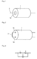
- FIG. 1 shows a closed path magnetic core (bead core) 1 formed of a soft magnetic material having a high resistivity.
- the magnetic core 1 is shaped cylindrical, has a through-hole 1a along its center axis, and is attached on a signal line 2 such that the signal line 2 is inserted through the through-hole 1a, thereby functioning as a bead type noise filter.
- the magnetic core 1 may alternatively be provided with a plurality of through-holes 1a (refer to Fig.2).
- the magnetic core 1 has been conventionally formed of Ni-Zn ferrite which has a high resistivity (10 2 to 10 5 ⁇ m) so as to duly work in such a high frequency band. Also, the magnetic core 1 is required to have a high resistivity so as to keep away from troubles even when the signal line 2 inserted through the through-hole 1a is not provided with an insulating coat thus possibly making direct contact therewith, which is another reason for using Ni-Zn for the magnetic core 1.
- Ni-Zn ferrite containing en expensive material of Ni pushes up the cost of the bead type noise filter in spite of its simple structure.
- conventional general Mn-Zn ferrite is an inexpensive soft ferrite but has a resistivity measuring as low as 10 1 to 10 0 ⁇ m. Consequently, the magnetic core 1 formed of Mn-Zn ferrite cannot be used in a high frequency band, because eddy current loss increases strikingly in a frequency band lower than a signal frequency band where noises are required to be suppressed. Also, there is another problem with Mn-Zn ferrite that the signal line 2 without an insulating coat must not be disposed in direct contact with the magnetic core 1 when inserted through the through-hole 1a.
- Mg-Zn ferrite is another inexpensive soft ferrite.
- Mg-Zn ferrite is inferior to other soft ferrites in soft magnetic properties, such as initial permeability and saturation magnetic flux density, and so the magnetic core 1, when formed of Mg-Zn ferrite, must have an increased dimension in order to achieve equivalent characteristics as a bead type noise filter.
- the magnetic core 1 when used to suppress noises in the signal line 2 (here, particularly a power wire) where ripple surge and surge noise present a problem, the magnetic core 1 must have its dimension further increased for prevention of magnetic saturation. Consequently, Mg-Zn ferrite is not used as a bead type noise filter.
- an equivalent circuit of a bead type noise filter is represented as a parallel circuit consisting of a series circuit of an inductance L component and a resistance R component, and a capacitance component C.
- the inductance L component, the resistance R component, and the capacitance C component may be referred to simply as L component, R component, and C component, respectively, as appropriate.
- of the bead type noise filter can be split into a reactance X component (hereinafter referred to simply as X component, as appropriate) and a resistance R component as follows:
- ⁇ (X 2 + R 2 )
- the X component is dominant in a frequency band of the signal to be transmitted, which means that the bead type noise filter, in conjunction with the C component at the signal line, functions as a low-pass filter, and blocks passage of noise components superposed on the signal.
- the noise components blocked and prevented from passing may possibly affect other circuits.
- the R component is dominant and converts noise components including the radiation noises into thermal energy, which constitutes a noise removing factor. Noises can be removed more safely and reliably when converted into thermal energy than when blocked by a low-pass filter.
- a frequency at which the X and R components have an equal value is a marginal frequency where dominance changes over between the X component to reflect noises and the R component to convert noises into thermal energy.
- the X-R cross point of a bead type noise filter constituted by a magnetic core formed of the aforementioned Ni-Zn ferrite is found approximately at 10 MHz which belongs to a high frequency band, and its reactance X component still keeps increasing in a high frequency band. So, if such a bead type noise filter using Ni-Zn ferrite is attached on an input signal line of a high impedance digital circuit having a capacitance of several pF, such as a C-MOS inverter, digital signals inputted suffer waveform distortion, such as ringing, undershoot, and overshoot.
- a bead type noise filter with a magnetic core formed of non-Ni-Zn ferrite has been demanded.
- a bead type noise filter which has a lower X-R cross point than one with a magnetic core formed of Ni-Zn ferrite, and which suppresses noises mainly by means of an R component in a safe and reliable manner is demanded.
- the present invention has been made in light of the demand described above, and it is an object of the present invention to provide an inexpensive bead type noise filter which suppresses noises without distorting the waveform of a transmission signal, such as a digital signal, in order to deal with higher frequency and digitalization of signals in recent electronic devices.
- the object of the present invention is to provide a bead type noise filter with a magnetic core formed of inexpensive Mn-Zn ferrite which has its resistivity significantly increased so as to achieve soft magnetic properties comparable to those of Ni-Zn ferrite in a high frequency band for the purpose of suppressing radiation noises of several 10 to several 100 MHz, also to provide an inexpensive bead type noise filter which allows a signal wire or power wire without an insulating coat to be inserted therethrough in a direct contact manner if needed.
- the object of the present invention is to eventually provide a high-performance bead type noise filter which, on top of accomplishing the above object, suppresses noises mainly by means of an R component in a safe and reliable manner so as not to distort the waveform of transmission signals.
- the magnetic core is formed of a soft magnetic material which has a real part of complex relative permittivity ranging from 1,000 up to 20,000 at 1 kHz, and 50 or lower at 1 MHz, and which has a resistivity of 150 ⁇ m or higher.
- the bead type noise filter can be fabricated inexpensively while it is provided with a significantly high resistivity and at the same time achieves a soft magnetic property comparable with that of Ni-Zn ferrite in a high frequency band thus enabling suppression of radiation noises of several ten to several hundred MHz.
- the magnetic core is formed of Mn-Zn ferrite which has a basic component composition comprising: 44.0 to 50.0 (50.0 excluded) mol % Fe 2 O 3 ; 4.0 to 26.5 mol % ZnO; 0.1 to 8.0 mol % at least one of TiO 2 and SnO 2 ; and the rest consisting of MnO. Consequently, the bead type noise filter can be fabricated inexpensively while it is adapted to suppress noises mainly by means of an R component in a safer and more reliable manner without distorting the waveform of transmission signals.
- the magnetic core is formed of Mn-Zn ferrite which has a basic component composition comprising: 44.0 to 50.0 (50.0 excluded) mol % Fe 2 O 3 ; 4.0 to 26.5 mol % ZnO; 0.1 to 8.0 mol % at least one of TiO 2 and SnO 2 ; 0.1 to 16.0 mol % CuO; and the rest consisting of MnO. Consequently, the bead type noise filter provided can be fabricated inexpensively while achieving high performance, as is the case with Claim 2.
- a bead type noise filter is constituted by a magnetic core (bead core) 1 which is formed of a soft magnetic material having a high resistivity, and through which a signal line (or a power line) 2 is inserted.
- the magnetic core 1 is shaped cylindrical and has a through-hole 1a along its center axis, through which the signal line 2 passes.
- a magnetic core 1 is formed of the same material as the aforementioned magnetic core 1 shown in Fig. 1, shaped also cylindrical, but has two through-holes la, and a signal line 2 goes through one thereof and turns back so as to go through the other one.
- an equivalent circuit of a bead type noise filter is represented such that a series circuit of an inductance L component and a resistance R component, and a capacitance C component are connected to each other in parallel.
- the present invention is applied to a bead type noise filter which is shaped as shown in Figs. 1 and 2, and which has an equivalent circuit as shown in Fig. 3.
- Mn-Zn ferrite containing 50.0 mol % or more Fe 2 O 3 is inexpensive and exhibits a favorable characteristic, but has a very low resistivity. Therefore, a bead type noise filter with a magnetic core formed of such Mn-Zn ferrite cannot be used in a high frequency band, and is not allowed to get in touch a signal line without an insulating coat.
- the eventual object of the present invention namely, realization of a high-performance bead type noise filter capable of suppressing noises mainly by means of an R component in a safe and reliable manner so as not to distort the waveform of transmission signals cannot be achieved simply by using a high resistivity ferrite like Ni-Zn ferrite.
- a reactance X component still keeps increasing in a high frequency band. So, if a bead type noise filter constituted by such a magnetic core is attached on an input signal line of a high-impedance digital circuit, the waveform of the input digital signal is caused to undergo distortion, such as overshoot, ringing, and the like.
- the imaginary part ⁇ " is a causative component for dielectric loss.
- a capacitance C component between the winding (the signal line wound around the magnetic core) is small.
- a capacitance C component exists not only between the winding but also between the winding and the magnetic core, and therefore depends on the real part ⁇ ' of the complex relative permittivity of the magnetic core. For example, in case of Mn-Zn ferrite having a very large real part ⁇ ' of complex relative permittivity, a capacitance C component generated between the winding and the magnetic core is very large.
- a capacitance C component depends largely on the real part ⁇ ' of the complex relative permittivity of the magnetic core.
- the present inventors, et al. produced bead type noise filters with Mn-Zn ferrites having same L components and R components, measured their impedance characteristics, and found out the following.
- the real parts ⁇ ' of the complex relative permittivity of the conventional general Mn-Zn ferrite and the Ni-Zn ferrite are kept substantially constant, with less than single-digit variance if any, from a low frequency band through a high frequency band.
- the present inventors, et al. came up with a bead type noise filter constituted by a magnetic core formed of a soft magnetic material which exhibits a characteristic that the real part ⁇ ' of complex relative permittivity varies very largely from a low frequency band through a high frequency band.
- the X-R cross point is found toward a low frequency band because the real part ⁇ ' of the complex relative permittivity is large to some extent in a lower frequency band, and the impedance characteristic is excellent in a high frequency band because the real part ⁇ ' of the complex relative permittivity is small in a high frequency.
- a magnetic core is set to have a resistivity of 150 ⁇ m or higher.
- a real part ⁇ ' of complex relative permittivity of a magnetic core is set to range between 1,000 and 20,000 at 1 kHz, and from 50 downward at 1 MHz.
- the X-R cross point in a bead type noise filter moves toward a lower frequency, for example 5 MHz.
- the bead types noise filters are constituted by magnetic cores formed of soft magnetic materials which are arranged to have a real part of complex relative permittivity ranging from 1,000 up to 20,000 at 1 kHz, and from 50 downward at 1 MHz, and a resistivity of 150 ⁇ m or higher.
- Each of the magnetic cores has a through-hole so as to form a closed magnetic path, and is attached on a signal line such that the signal line passes through the through-hole.
- Table 1 below shows basic compositions on sample magnetic cores. Some of the magnetic cores are formed of soft magnetic materials according to the present invention, and the others are formed of conventional soft magnetic materials for comparison.
- sample magnetic cores (Samples 1 to 5) were prepared.
- Material powders selected out of Fe 2 O 3 , ZnO, TiO 2 , SnO 2 , CuO, MnO, NiO, and MgO and pre-weighed for respective compositions shown in Table 1 were mixed by a ball mill to produce respective mixtures, and the respective mixtures were calcined at 900 degrees C for 2 hours in the atmosphere.
- the respective mixtures calcined were pulverized by a ball mill into particles with a grain diameter averaging about 1.4 ⁇ m.
- Samples 1 to 5 with an outer diameter of 3.2 mm, an inner diameter of 1.6 mm, and a height of 6 mm were obtained.
- Sample 5 formed of Mg-Zn ferrite is low in initial permeability ⁇ i and saturation magnetic flux density Bs and therefore is not advantageous compared to Samples 1 to 4. Especially, since a bead type noise filter is required to be prevented from becoming magnetically saturated by a ripple current and a surge noise, Sample 5 with a low saturation magnetic flux density Bs must have an increased dimension.
- Sample 3 formed of general Mn-Zn ferrite is favorable in initial permeability ⁇ i and saturation magnetic flux density Bs, but very low in resistivity ⁇ v therefore hampering its usage in a high frequency band. Also, Sample 3 must not be in a direct contact with an uninsulated signal line, thus inevitably limiting its applications.
- Sample 1 formed of an inventive Mn-Zn ferrite (according to Claim 2), Sample 2 formed of another inventive Mn-Zn ferrite (according to Claim 3), and Sample 4 formed of Ni-Zn ferrite have favorable initial permeability ⁇ i, saturation magnetic flux density Bs, and resistivity ⁇ v.
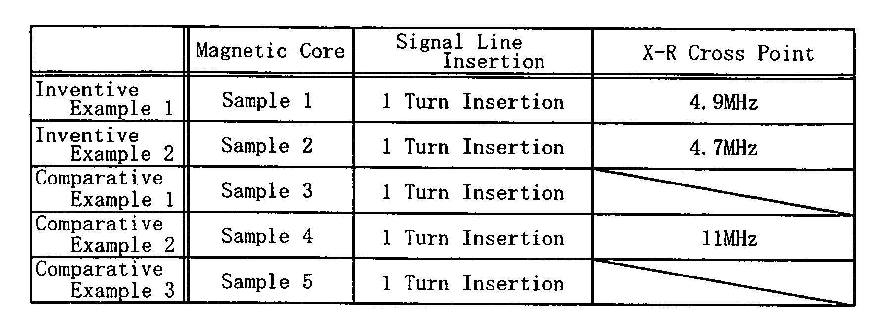
- Samples 1 to 5 (bead cores) obtained according to Process 1 described above was attached on a signal line as a bead type noise filter such that the signal line was inserted through the core with one turn therearound (one turn insertion). Examples thus prepared are shown in Table 3 below with X-R cross points measured.
- Fig. 4 Measurements of frequency characteristics of impedance on Examples 1 to 5 are shown in Fig. 4.
- the impedance characteristics shown in Fig. 4 are practical characteristics as bead type noise filters.
- Comparative Example 1 has its impedance characteristic significantly lowered compared to other examples (Inventive Examples 1 and 2, and Comparative Examples 2 and 3). This is because Mn-Zn ferrite has a low resistivity ⁇ v.
- Comparative Example 3 has a lower impedance characteristic than other examples (Inventive Examples 1 and 2, and Comparative Examples 1 and 2). This is because Mg-Zn ferrite has a low initial permeability ⁇ i.
- Inventive Examples 1 and 2 have a favorable impedance characteristic in a high frequency band.
- Inventive Example 1 has its X-R cross point found in the vicinity of 5 MHz.
- Comparative Example 2 has its X-R cross point found in the vicinity of 10 MHz as shown in Fig. 6. This is because, as shown in Table 2, the real part ⁇ ' of complex relative permittivity on Sample 1 (Inventive Example 1) and Sample 2 (Inventive Example 2) varies greatly between 1 kHz and 1 MHz while that on Sample 4 (Comparative Example 2) varies little.
- the embodiment described above refers to the bead type noise filters which both have a resistivity of 150 ⁇ m or higher, and which respectively have a real part ⁇ ' of complex relative permittivity of 12,320 and 10,970 at 1 kHz, and 32 and 28 at 1 MHz (Inventive Examples 1 and 2), but it was verified that any bead type noise filters having its real part ⁇ ' of complex relative permittivity falling within the range specified in Claim 1 can achieve an effect equivalent or substantially equivalent to that of the embodiment described above.
- the embodiment described above refers to the bead type noise filter whose magnetic core is formed of Mn-Zn ferrite having a basic component composition comprising: 47.0 mol % Fe 2 O 3 ; 10.5 mol % ZnO; 1.0 mol % TiO 2 ; and the rest (41.5 mol %) consisting of MnO (Inventive Example 1), but it was verified that any bead type noise filters having its basic component composition falling within the range specified in Claim 2 can achieve an effect equivalent or substantially equivalent to that of the embodiment described above.
- the embodiment described above refers to the bead type noise filter whose magnetic core is formed of Mn-Zn ferrite having a basic component composition comprising: 47.0 mol % Fe 2 O 3 ; 10.5 mol % ZnO; 0.5 mol % SnO 2 ; 1.5 mol % CuO; and the rest (40.5 mol %) consisting of MnO (Inventive Example 2), but it was verified that any bead type noise filters having its basic component composition falling within the range specified in Claim 2 can achieve an effect equivalent or substantially equivalent to that of the embodiment described above.
- a bead type noise filter according to the present invention is helpful in simply and inexpensively suppressing high frequency noises radiated from a signal line of recent electronic devices that are coming out with reduced dimension and enhanced performance, and especially is suited for suppressing noises without distorting the waveform of an input digital signal.
Landscapes
- Engineering & Computer Science (AREA)
- Power Engineering (AREA)
- Microelectronics & Electronic Packaging (AREA)
- Coils Or Transformers For Communication (AREA)
- Filters And Equalizers (AREA)
- Soft Magnetic Materials (AREA)
Abstract
A bead type noise filter according to the present invention is constituted by a
magnetic core 1 formed of Mn-Zn ferrite having its resistivity increased so as to improve
a high frequency characteristic, and having its permittivity lowered, and thereby can
successfully suppress radiation noises without distorting the waveform of transmission
signals. The magnetic core 1 constituting the bead type noise filter is formed of a high
resistivity soft magnetic material, is shaped cylindrical, and has at least one
through-hole 1a so as to form a closed magnetic path, and the bead type noise filter is
attached on a signal line 2 such that the signal line 2 is inserted through the
through-hole 1a. The soft magnetic material has a real part of complex relative
permittivity ranging from 1,000 up to 20,000 at 1 kHz and 50 or lower at 1 MHz, and
has a resistivity of 150 Ω m or higher.
Description
The present invention relates to a bead type noise filter which is used
on a signal wire (signal line) and a power wire (DC line, and the like) mounted on a
circuit board, and which suppresses unwanted radiation noises.
While electronic devices are coming out with reduced dimension and
enhanced performance, high frequency noises radiated from a signal wire and a power
wire (hereinafter referred to generically as "signal line") are becoming a major problem.
These noises can be suppressed most simply by inserting the signal line through a
closed magnetic path core called "bead core" shaped toroidal or cylindrical. Practically,
the signal line is often inserted through the core with one turn therearound (one turn
insertion), and in some cases, the core may be provided with a plurality of through-holes,
through which the signal line is inserted for a plurality of turns therearound.
A bead type noise filter, which leverages the noise suppressing method
described above, will hereinafter be explained with reference to Fig. 1. Fig. 1 shows a
closed path magnetic core (bead core) 1 formed of a soft magnetic material having a high
resistivity. The magnetic core 1 is shaped cylindrical, has a through-hole 1a along its
center axis, and is attached on a signal line 2 such that the signal line 2 is inserted
through the through-hole 1a, thereby functioning as a bead type noise filter. In this
connection, the magnetic core 1 may alternatively be provided with a plurality of
through-holes 1a (refer to Fig.2).
In order to suppress unwanted radiation noises of several ten to
several hundred MHz, the magnetic core 1 has been conventionally formed of Ni-Zn
ferrite which has a high resistivity (102 to 105 Ωm) so as to duly work in such a high
frequency band. Also, the magnetic core 1 is required to have a high resistivity so as to
keep away from troubles even when the signal line 2 inserted through the through-hole
1a is not provided with an insulating coat thus possibly making direct contact therewith,
which is another reason for using Ni-Zn for the magnetic core 1. The usage of Ni-Zn
ferrite containing en expensive material of Ni pushes up the cost of the bead type noise
filter in spite of its simple structure.
On the other hand, conventional general Mn-Zn ferrite is an
inexpensive soft ferrite but has a resistivity measuring as low as 101 to 100 Ωm.
Consequently, the magnetic core 1 formed of Mn-Zn ferrite cannot be used in a high
frequency band, because eddy current loss increases strikingly in a frequency band
lower than a signal frequency band where noises are required to be suppressed. Also,
there is another problem with Mn-Zn ferrite that the signal line 2 without an insulating
coat must not be disposed in direct contact with the magnetic core 1 when inserted
through the through-hole 1a.
Mg-Zn ferrite is another inexpensive soft ferrite. Mg-Zn ferrite,
however, is inferior to other soft ferrites in soft magnetic properties, such as initial
permeability and saturation magnetic flux density, and so the magnetic core 1, when
formed of Mg-Zn ferrite, must have an increased dimension in order to achieve
equivalent characteristics as a bead type noise filter. Especially, when used to
suppress noises in the signal line 2 (here, particularly a power wire) where ripple surge
and surge noise present a problem, the magnetic core 1 must have its dimension further
increased for prevention of magnetic saturation. Consequently, Mg-Zn ferrite is not
used as a bead type noise filter.
Referring to Fig. 3, an equivalent circuit of a bead type noise filter is
represented as a parallel circuit consisting of a series circuit of an inductance L
component and a resistance R component, and a capacitance component C.
Hereinafter, the inductance L component, the resistance R component, and the
capacitance C component may be referred to simply as L component, R component, and
C component, respectively, as appropriate.
In Fig. 3, in a frequency band of a signal to be transmitted (signal
frequency band), there is a relation of: L >> R, where L = value of the L component, and
R = value of the R component, each representing impedance I Z | value. Hence, the
series circuit of the L and R components in the bead type noise filter functions as
inductance (almost L component only), and the signal to be transmitted does not incur a
loss caused due to the R component. Thus, the bead type noise filter, in conjunction
with the C component at the signal line, constitutes a low-pass filter in terms of a circuit.
But, since the value of the L component is small, and since a cutoff frequency is higher
than a frequency band of the signal to be transmitted, the transmission loss of the
signal can be ignored.
In a frequency band higher than the frequency band of a signal to be
transmitted, there is a relation of: L << R, so the series circuit of the L and R
components functions as resistance (almost R component only), and absorbs noises as
heat. This contributes to effectively suppressing, in particular, unwanted radiation
noises.
The impedance |Z| of the bead type noise filter can be split into a
reactance X component (hereinafter referred to simply as X component, as appropriate)
and a resistance R component as follows:
|Z| = √ (X2 + R2 )
When, an AC magnetic field is applied to the magnet core of the bead
type noise filter, its complex permeability µ can be represented as follows:
µ = √ (µ'2 + µ"2 )
where µ' is a real part, and µ" is an imaginary part. The X component of the bead type
noise filter (the component may be "L component") is generated by the real part µ' while
the R component thereof is generated by the imaginary part µ".
Consequently, the X component is dominant in a frequency band of the
signal to be transmitted, which means that the bead type noise filter, in conjunction
with the C component at the signal line, functions as a low-pass filter, and blocks
passage of noise components superposed on the signal. However, the noise components
blocked and prevented from passing may possibly affect other circuits. On the other
hand, in a high frequency band where radiation noises are generated, the R component
is dominant and converts noise components including the radiation noises into thermal
energy, which constitutes a noise removing factor. Noises can be removed more safely
and reliably when converted into thermal energy than when blocked by a low-pass filter.
A frequency at which the X and R components have an equal value,
namely an X-R cross point, is a marginal frequency where dominance changes over
between the X component to reflect noises and the R component to convert noises into
thermal energy. Generally, the more the R component to convert noises into thermal
energy is, the better it is in terms of removing noises, so a lower X-R cross point is more
preferred if impedance characteristic is equal.
And, if the X component is large and the R component is small in a
high frequency band, an LC resonance with a large Q (index to show inductance
performance) is generated by the capacitance C component at the signal line, whereby a
digital signal inputted may suffer waveform distortion, such as ringing, depending on a
circuit to which the bead type noise filter is connected. Consequently, in a high
frequency band, the smaller the X component is, the better it is.
In connection with the above-described relation between a frequency
(band) and X and R components, the X-R cross point of a bead type noise filter
constituted by a magnetic core formed of the aforementioned Ni-Zn ferrite is found
approximately at 10 MHz which belongs to a high frequency band, and its reactance X
component still keeps increasing in a high frequency band. So, if such a bead type
noise filter using Ni-Zn ferrite is attached on an input signal line of a high impedance
digital circuit having a capacitance of several pF, such as a C-MOS inverter, digital
signals inputted suffer waveform distortion, such as ringing, undershoot, and overshoot.
This is caused due to the generation of the above-described LC resonance having a
comparatively large Q. For the reason of this waveform distortion as well as the
aforementioned expensiveness of Ni-Zn ferrite, a bead type noise filter with a magnetic
core formed of non-Ni-Zn ferrite has been demanded. Especially, a bead type noise
filter which has a lower X-R cross point than one with a magnetic core formed of Ni-Zn
ferrite, and which suppresses noises mainly by means of an R component in a safe and
reliable manner is demanded.
The present invention has been made in light of the demand described
above, and it is an object of the present invention to provide an inexpensive bead type
noise filter which suppresses noises without distorting the waveform of a transmission
signal, such as a digital signal, in order to deal with higher frequency and digitalization
of signals in recent electronic devices.
Specifically, the object of the present invention (according to Claim 1)
is to provide a bead type noise filter with a magnetic core formed of inexpensive Mn-Zn
ferrite which has its resistivity significantly increased so as to achieve soft magnetic
properties comparable to those of Ni-Zn ferrite in a high frequency band for the purpose
of suppressing radiation noises of several 10 to several 100 MHz, also to provide an
inexpensive bead type noise filter which allows a signal wire or power wire without an
insulating coat to be inserted therethrough in a direct contact manner if needed.
Further, the object of the present invention (according to Claims 2 and 3) is to
eventually provide a high-performance bead type noise filter which, on top of
accomplishing the above object, suppresses noises mainly by means of an R component
in a safe and reliable manner so as not to distort the waveform of transmission signals.
According to Claim 1 of the present invention, in a bead type noise
filter which comprises a magnetic core having a through-hole so as to form a closed
magnetic path, and which is attached on one of a signal wire and a power wire such that
the wire passes through the closed magnetic path of the magnetic core, the magnetic
core is formed of a soft magnetic material which has a real part of complex relative
permittivity ranging from 1,000 up to 20,000 at 1 kHz, and 50 or lower at 1 MHz, and
which has a resistivity of 150 Ωm or higher. Consequently, the bead type noise filter
can be fabricated inexpensively while it is provided with a significantly high resistivity
and at the same time achieves a soft magnetic property comparable with that of Ni-Zn
ferrite in a high frequency band thus enabling suppression of radiation noises of several
ten to several hundred MHz.
According to Claim 2 of the present invention, the magnetic core is
formed of Mn-Zn ferrite which has a basic component composition comprising: 44.0 to
50.0 (50.0 excluded) mol % Fe2O3; 4.0 to 26.5 mol % ZnO; 0.1 to 8.0 mol % at least one of
TiO2 and SnO2; and the rest consisting of MnO. Consequently, the bead type noise
filter can be fabricated inexpensively while it is adapted to suppress noises mainly by
means of an R component in a safer and more reliable manner without distorting the
waveform of transmission signals.
And, according to Claim 3 of the present invention, the magnetic core
is formed of Mn-Zn ferrite which has a basic component composition comprising: 44.0 to
50.0 (50.0 excluded) mol % Fe2O3; 4.0 to 26.5 mol % ZnO; 0.1 to 8.0 mol % at least one of
TiO2 and SnO2; 0.1 to 16.0 mol % CuO; and the rest consisting of MnO. Consequently,
the bead type noise filter provided can be fabricated inexpensively while achieving high
performance, as is the case with Claim 2.
Preferred embodiments of the present invention will hereinafter be
described with reference to Figs. 1 to 6.
Referring to Fig. 1, a bead type noise filter is constituted by a magnetic
core (bead core) 1 which is formed of a soft magnetic material having a high resistivity,
and through which a signal line (or a power line) 2 is inserted. The magnetic core 1 is
shaped cylindrical and has a through-hole 1a along its center axis, through which the
signal line 2 passes. Referring to Fig. 2 showing another bead type noise filter, a
magnetic core 1 is formed of the same material as the aforementioned magnetic core 1
shown in Fig. 1, shaped also cylindrical, but has two through-holes la, and a signal line
2 goes through one thereof and turns back so as to go through the other one.
Referring to Fig. 3, an equivalent circuit of a bead type noise filter is
represented such that a series circuit of an inductance L component and a resistance R
component, and a capacitance C component are connected to each other in parallel.
The present invention is applied to a bead type noise filter which is
shaped as shown in Figs. 1 and 2, and which has an equivalent circuit as shown in Fig.
3.
Conventional general Mn-Zn ferrite containing 50.0 mol % or more
Fe2O3 is inexpensive and exhibits a favorable characteristic, but has a very low
resistivity. Therefore, a bead type noise filter with a magnetic core formed of such
Mn-Zn ferrite cannot be used in a high frequency band, and is not allowed to get in
touch a signal line without an insulating coat.
The present inventors, et al. disclosed in, for example, Japanese
Patent Nos. 3108803 and 3108804 that Mn-Zn ferrite, when containing less than 50
mol % Fe2O3, and an appropriate amount of at least one of TiO2 and SnO2, has its
resistivity significantly increased. However, the eventual object of the present
invention, namely, realization of a high-performance bead type noise filter capable of
suppressing noises mainly by means of an R component in a safe and reliable manner so
as not to distort the waveform of transmission signals cannot be achieved simply by
using a high resistivity ferrite like Ni-Zn ferrite. Specifically, since a magnetic core
formed of Ni-Zn ferrite has its X-R cross point found at 10 MHz or higher which belongs
to a high frequency band, as described later, a reactance X component still keeps
increasing in a high frequency band. So, if a bead type noise filter constituted by such
a magnetic core is attached on an input signal line of a high-impedance digital circuit,
the waveform of the input digital signal is caused to undergo distortion, such as
overshoot, ringing, and the like.
When an AC magnetic field is applied to a magnetic core of a bead type
noise filter whose equivalent circuit is generally represented by Fig. 3, permittivity ε is
expressed by a complex number as follows:
ε = √ (ε'2 + ε"2 )
where ε' is a real part of complex relative permittivity, and ε" is an imaginary part
thereof. The imaginary part ε" is a causative component for dielectric loss.
Since such a bead type noise filter is often attached on a signal line
such that the signal line is inserted through a magnetic core (bead core) with one turn
therearound (one turn insertion), and since a distance between input and output
terminals is large, a capacitance C component between the winding (the signal line
wound around the magnetic core) is small. A capacitance C component exists not only
between the winding but also between the winding and the magnetic core, and therefore
depends on the real part ε' of the complex relative permittivity of the magnetic core.
For example, in case of Mn-Zn ferrite having a very large real part ε' of complex relative
permittivity, a capacitance C component generated between the winding and the
magnetic core is very large. Especially, since the winding of a bead type noise filter
passes through the magnetic core in a close contact manner, a capacitance C component
depends largely on the real part ε' of the complex relative permittivity of the magnetic
core.
The present inventors, et al. produced bead type noise filters with
Mn-Zn ferrites having same L components and R components, measured their
impedance characteristics, and found out the following.
In conventional general Mn-Zn ferrite having a large real part ε' of
complex relative permittivity (the C component is large), the X-R cross point is found
toward a low frequency, but the impedance characteristic in a high frequency band is
inferior. On the other hand, in Ni-Zn ferrite having a small real part ε' of complex
relative permittivity (the C component is small), the X-R cross point is found toward a
high frequency, but the impedance characteristic in a high frequency band is superior.
Further, the real parts ε' of the complex relative permittivity of the conventional general
Mn-Zn ferrite and the Ni-Zn ferrite are kept substantially constant, with less than
single-digit variance if any, from a low frequency band through a high frequency band.
Based on the above finding, the present inventors, et al. came up with
a bead type noise filter constituted by a magnetic core formed of a soft magnetic
material which exhibits a characteristic that the real part ε' of complex relative
permittivity varies very largely from a low frequency band through a high frequency
band. In the bead type noise filter described above, the X-R cross point is found toward
a low frequency band because the real part ε' of the complex relative permittivity is
large to some extent in a lower frequency band, and the impedance characteristic is
excellent in a high frequency band because the real part ε' of the complex relative
permittivity is small in a high frequency.
According to the present invention, a magnetic core is set to have a
resistivity of 150 Ωm or higher. There is no definitely telling whether a problem occurs
or not when a copper wire with no insulating coat is wound directly on a magnetic core
because it depends on a voltage applied, but a magnetic core having a resistivity of 150
Ωm or higher is supposed to duly work without problems in fairly extensive
applications.
Also, in the present invention, a real part ε' of complex relative
permittivity of a magnetic core is set to range between 1,000 and 20,000 at 1 kHz, and
from 50 downward at 1 MHz. With such a magnetic core in which the real part ε' of
complex relative permittivity varies significantly from a low frequency through a high
frequency as described above, the X-R cross point in a bead type noise filter moves
toward a lower frequency, for example 5 MHz.
Embodiments of bead type noise filters according to the present
invention will hereinafter be described. The bead types noise filters are constituted by
magnetic cores formed of soft magnetic materials which are arranged to have a real part
of complex relative permittivity ranging from 1,000 up to 20,000 at 1 kHz, and from 50
downward at 1 MHz, and a resistivity of 150 Ωm or higher. Each of the magnetic cores
has a through-hole so as to form a closed magnetic path, and is attached on a signal line
such that the signal line passes through the through-hole.
Table 1 below shows basic compositions on sample magnetic cores.
Some of the magnetic cores are formed of soft magnetic materials according to the
present invention, and the others are formed of conventional soft magnetic materials for
comparison.
| Basic Composition (mol%) | ||||||||
| Fe2O3 | MnO | ZnO | TiO2 | SnO2 | NiO | MgO | CuO | |
| Sample 1 | 47.0 | 41. 5 | 10.5 | 1.0 | ― | ― | ― | ― |
| Sample 2 | 47.0 | 40.5 | 10.5 | ― | 0.5 | -- | -- | 1. 5 |
| Sample 3 | 53.0 | 37.5 | 9.5 | ― | ― | ― | ― | ― |
| Sample 4 | 48.5 | -- | 31.5 | ― | ― | 16.0 | ― | 5.0 |
| Sample 5 | 48. 5 | 2.0 | 18. 5 | ― | ― | ― | 31.0 | ― |
Referring to Table 1, five kinds of sample magnetic cores (Samples 1 to
5) were prepared. Material powders selected out of Fe2O3, ZnO, TiO2, SnO2, CuO, MnO,
NiO, and MgO and pre-weighed for respective compositions shown in Table 1 were
mixed by a ball mill to produce respective mixtures, and the respective mixtures were
calcined at 900 degrees C for 2 hours in the atmosphere. The respective mixtures
calcined were pulverized by a ball mill into particles with a grain diameter averaging
about 1.4 µm. Then, the respective mixtures pulverized were mixed with polyvinyl
alcohol added, were granulated, and press-molded under a pressure of 80 MPa into
respective green compacts each with a toroidal configuration. Green compacts
intended for Samples 1 to 3 were sintered at 1,150 degrees C for 3 hours in an
atmosphere with its oxygen partial pressure controlled by pouring in nitrogen, while
green compacts intended for Samples 4 and 5 were sintered at 1,150 degrees C for 3
hours in the atmosphere.
Thus, Samples 1 to 5 with an outer diameter of 3.2 mm, an inner
diameter of 1.6 mm, and a height of 6 mm were obtained. Samples (sample magnetic
cores for bead type noise filters) 1 to 5 thus prepared were measured on: initial
permeability µi at 0.1 MHz; saturation magnetic flux density Bs at 1,194 A/m;
resistivity ρv (Ωm); and real parts ε' of complex relative permittivity at 1 kHz and 1
MHz, and the measurements are shown in Table 2 below.
| µi (0.1MHz) | Bs (1194A/m) | ρv [Ωm] | ε' | ||
| (1kHz) | (1MHz) | ||||
| Sample 1 | 857 | 410 | 103 | 12,320 | 32 |
| Sample 2 | 861 | 390 | 103 | 10,970 | 28 |
| Sample 3 | 853 | 420 | 10-1 | 58,430 | 18,800 |
| Sample 4 | 864 | 370 | 104 | 22 | 17 |
| Sample 5 | 487 | 250 | 104 | 56 | 51 |
Sample 5 formed of Mg-Zn ferrite is low in initial permeability µi and
saturation magnetic flux density Bs and therefore is not advantageous compared to
Samples 1 to 4. Especially, since a bead type noise filter is required to be prevented
from becoming magnetically saturated by a ripple current and a surge noise, Sample 5
with a low saturation magnetic flux density Bs must have an increased dimension.
Sample 3 formed of general Mn-Zn ferrite is favorable in initial
permeability µi and saturation magnetic flux density Bs, but very low in resistivity ρv
therefore hampering its usage in a high frequency band. Also, Sample 3 must not be in
a direct contact with an uninsulated signal line, thus inevitably limiting its
applications.
Sample 1 formed of an inventive Mn-Zn ferrite (according to Claim 2),
Sample 2 formed of another inventive Mn-Zn ferrite (according to Claim 3), and Sample
4 formed of Ni-Zn ferrite have favorable initial permeability µi, saturation magnetic flux
density Bs, and resistivity ρv.
Each of Samples 1 to 5 (bead cores) obtained according to Process 1
described above was attached on a signal line as a bead type noise filter such that the
signal line was inserted through the core with one turn therearound (one turn insertion).
Examples thus prepared are shown in Table 3 below with X-R cross points measured.

Measurements of frequency characteristics of impedance on Examples
1 to 5 are shown in Fig. 4. The impedance characteristics shown in Fig. 4 are practical
characteristics as bead type noise filters.
As shown in Fig. 4, in a frequency from 10 MHz upward which is a
crucial frequency band for noise suppression, Comparative Example 1 has its
impedance characteristic significantly lowered compared to other examples (Inventive
Examples 1 and 2, and Comparative Examples 2 and 3). This is because Mn-Zn ferrite
has a low resistivity ρv.
Comparative Example 3 has a lower impedance characteristic than
other examples (Inventive Examples 1 and 2, and Comparative Examples 1 and 2).
This is because Mg-Zn ferrite has a low initial permeability µi.
Inventive Examples 1 and 2, and Comparative Example 2 have a
favorable impedance characteristic in a high frequency band.
Inventive Examples 1 and 2, and Comparative Example 2, which, from
the various measurement results in Processes 1 and 2 described above, looked like most
promising candidates for bead type noise filters, were further examined.
Each of the impedances on Inventive Examples 1 and 2, and
Comparative Example 2 measured in Process 2 was split into a reactance X component
and a resistance R component according to Formula (1) described above. The
component splits on Inventive Example 1 and Comparative Example 2 are shown
graphically in Figs. 5 and 6, respectively.
Referring to Fig. 5, Inventive Example 1 has its X-R cross point found
in the vicinity of 5 MHz. The component split on Inventive Example 2, which is not
shown, turned out much the same as with Inventive Example 1. On the other hand,
Comparative Example 2 has its X-R cross point found in the vicinity of 10 MHz as
shown in Fig. 6. This is because, as shown in Table 2, the real part ε' of complex
relative permittivity on Sample 1 (Inventive Example 1) and Sample 2 (Inventive
Example 2) varies greatly between 1 kHz and 1 MHz while that on Sample 4
(Comparative Example 2) varies little.
The above finding from the examination has shown that though both
Inventive Examples 1 and 2, and Comparative Example 2 have a satisfactory
impedance characteristic in a high frequency band thus meaning an effective function of
noise suppression, Inventive Examples 1 and 2 are superior to Comparative Example 2
in providing by far less chance of distorting the waveform of an input digital signal.
In explaining Claim 1 of the present invention, the embodiment
described above refers to the bead type noise filters which both have a resistivity of 150
Ωm or higher, and which respectively have a real part ε' of complex relative permittivity
of 12,320 and 10,970 at 1 kHz, and 32 and 28 at 1 MHz (Inventive Examples 1 and 2),
but it was verified that any bead type noise filters having its real part ε' of complex
relative permittivity falling within the range specified in Claim 1 can achieve an effect
equivalent or substantially equivalent to that of the embodiment described above.
In explaining Claim 2 of the present invention, the embodiment
described above refers to the bead type noise filter whose magnetic core is formed of
Mn-Zn ferrite having a basic component composition comprising: 47.0 mol % Fe2O3; 10.5
mol % ZnO; 1.0 mol % TiO2; and the rest (41.5 mol %) consisting of MnO (Inventive
Example 1), but it was verified that any bead type noise filters having its basic
component composition falling within the range specified in Claim 2 can achieve an
effect equivalent or substantially equivalent to that of the embodiment described above.
And, in explaining Claim 3 of the present invention, the embodiment
described above refers to the bead type noise filter whose magnetic core is formed of
Mn-Zn ferrite having a basic component composition comprising: 47.0 mol % Fe2O3; 10.5
mol % ZnO; 0.5 mol % SnO2; 1.5 mol % CuO; and the rest (40.5 mol %) consisting of MnO
(Inventive Example 2), but it was verified that any bead type noise filters having its
basic component composition falling within the range specified in Claim 2 can achieve
an effect equivalent or substantially equivalent to that of the embodiment described
above.
A bead type noise filter according to the present invention is helpful in
simply and inexpensively suppressing high frequency noises radiated from a signal line
of recent electronic devices that are coming out with reduced dimension and enhanced
performance, and especially is suited for suppressing noises without distorting the
waveform of an input digital signal.
Claims (3)
- A bead type noise filter which comprises a magnetic core having a through-hole so as to form a closed magnetic path, and which is attached on one of a signal wire and a power wire such that the wire passes through the closed magnetic path of the magnetic core,
characterized in that the magnetic core is formed of a soft magnetic material which has a real part of complex relative permittivity ranging from 1,000 up to 20,000 at 1 kHz, and 50 or lower at 1 MHz, and which has a resistivity of 150 Ωm or higher. - A bead type noise filter according to Claim 1, wherein the magnetic core is formed of Mn-Zn ferrite having a basic component composition comprising: 44.0 to 50.0 (50.0 excluded) mol % Fe2O3; 4.0 to 26.5 mol % ZnO; 0.1 to 8.0 mol % at least one of TiO2 and SnO2; and the rest consisting of MnO.
- A bead type noise filter according to Claim 1, wherein the magnetic core is formed of Mn-Zn ferrite having a basic component composition comprising: 44.0 to 50.0 (50.0 excluded) mol % Fe2O3; 4.0 to 26.5 mol % ZnO; 0.1 to 8.0 mol % at least one of TiO2 and SnO2; 0.1 to 16.0 mol % CuO; and the rest consisting of MnO.
Applications Claiming Priority (1)
| Application Number | Priority Date | Filing Date | Title |
|---|---|---|---|
| PCT/JP2003/012044 WO2005029517A1 (en) | 2003-09-22 | 2003-09-22 | Bead noise filter |
Publications (1)
| Publication Number | Publication Date |
|---|---|
| EP1569249A1 true EP1569249A1 (en) | 2005-08-31 |
Family
ID=34362504
Family Applications (1)
| Application Number | Title | Priority Date | Filing Date |
|---|---|---|---|
| EP03816939A Withdrawn EP1569249A1 (en) | 2003-09-22 | 2003-09-22 | Bead noise filter |
Country Status (4)
| Country | Link |
|---|---|
| US (1) | US7148767B2 (en) |
| EP (1) | EP1569249A1 (en) |
| CN (1) | CN1663003A (en) |
| WO (1) | WO2005029517A1 (en) |
Cited By (2)
| Publication number | Priority date | Publication date | Assignee | Title |
|---|---|---|---|---|
| WO2006007321A3 (en) * | 2004-06-17 | 2007-06-28 | Fci Americas Technology Inc | Electrical filter assembly having idc connection |
| WO2015176788A1 (en) * | 2014-05-21 | 2015-11-26 | Audi Ag | Energy store, energy store arrangement for a motor vehicle and motor vehicle |
Families Citing this family (9)
| Publication number | Priority date | Publication date | Assignee | Title |
|---|---|---|---|---|
| CN100468930C (en) * | 2006-03-17 | 2009-03-11 | 鸿富锦精密工业(深圳)有限公司 | Magnetic bead selection method for anti-electromagnetic interference power filter |
| US20140241217A1 (en) * | 2011-08-18 | 2014-08-28 | Zte Corporation | Headset device, headset, and method for processing signal by using headset device |
| JP6206654B2 (en) * | 2013-08-30 | 2017-10-04 | セイコーエプソン株式会社 | Liquid ejection device and head unit |
| JP6206655B2 (en) | 2013-08-30 | 2017-10-04 | セイコーエプソン株式会社 | Liquid ejection device and head unit |
| JP6421424B2 (en) * | 2014-03-07 | 2018-11-14 | 北川工業株式会社 | Bus bar assembly and method of manufacturing bus bar assembly |
| US9213510B1 (en) | 2014-06-13 | 2015-12-15 | Ricoh Company, Ltd. | Print scheduling mechanism |
| US9600214B2 (en) | 2014-06-13 | 2017-03-21 | Ricoh Company, Ltd. | Aggregate work volume estimation mechanism |
| CN106021811B (en) * | 2016-06-08 | 2019-04-02 | 福州大学 | A kind of magnetic material wideband complex permeability measuring method |
| JP6380773B2 (en) * | 2017-03-27 | 2018-08-29 | セイコーエプソン株式会社 | Liquid ejection device |
Family Cites Families (17)
| Publication number | Priority date | Publication date | Assignee | Title |
|---|---|---|---|---|
| JPS5636163Y2 (en) * | 1976-08-19 | 1981-08-26 | ||
| US4656451A (en) * | 1986-01-23 | 1987-04-07 | Ferronics, Inc. | Electronic noise suppressor |
| JPS6441202A (en) * | 1987-08-06 | 1989-02-13 | Mitsubishi Petrochemical Co | Cable shielding bead |
| JPS6441202U (en) | 1987-09-04 | 1989-03-13 | ||
| JPH05283223A (en) | 1992-04-03 | 1993-10-29 | Mitsubishi Electric Corp | Signal discriminator |
| US5500629A (en) * | 1993-09-10 | 1996-03-19 | Meyer Dennis R | Noise suppressor |
| US5455552A (en) * | 1994-05-03 | 1995-10-03 | Steward, Inc. | Ferrite common mode choke adapted for circuit board mounting |
| JPH08181478A (en) * | 1994-12-26 | 1996-07-12 | Kanegafuchi Chem Ind Co Ltd | Noise filter and manufacturing method thereof |
| JP3108804B2 (en) | 1998-08-19 | 2000-11-13 | ミネベア株式会社 | Mn-Zn ferrite |
| JP3108803B2 (en) | 1998-08-19 | 2000-11-13 | ミネベア株式会社 | Mn-Zn ferrite |
| JP3584439B2 (en) * | 2000-02-08 | 2004-11-04 | ミネベア株式会社 | Mn-Zn ferrite and method for producing the same |
| JP2002167272A (en) * | 2000-11-28 | 2002-06-11 | Minebea Co Ltd | METHOD OF MANUFACTURING Mn-Zn FERRITE |
| JP2003059712A (en) * | 2001-08-10 | 2003-02-28 | Minebea Co Ltd | Mn-Zn FERRITE AND WIRE WOUND COMPONENT |
| JP2003068515A (en) * | 2001-08-22 | 2003-03-07 | Minebea Co Ltd | Mn-Zn FERRITE AND WINDING COMPONENT |
| JP2003282318A (en) | 2002-03-22 | 2003-10-03 | Minebea Co Ltd | Signal discriminator |
| JP2003324014A (en) | 2002-04-30 | 2003-11-14 | Minebea Co Ltd | Bead core type noise filter |
| JP2004039787A (en) * | 2002-07-02 | 2004-02-05 | Minebea Co Ltd | Inductor |
-
2003
- 2003-09-22 WO PCT/JP2003/012044 patent/WO2005029517A1/en not_active Ceased
- 2003-09-22 EP EP03816939A patent/EP1569249A1/en not_active Withdrawn
- 2003-09-22 CN CN038143933A patent/CN1663003A/en active Pending
- 2003-09-22 US US10/515,494 patent/US7148767B2/en not_active Expired - Fee Related
Non-Patent Citations (1)
| Title |
|---|
| See references of WO2005029517A1 * |
Cited By (4)
| Publication number | Priority date | Publication date | Assignee | Title |
|---|---|---|---|---|
| WO2006007321A3 (en) * | 2004-06-17 | 2007-06-28 | Fci Americas Technology Inc | Electrical filter assembly having idc connection |
| US7307495B2 (en) * | 2004-06-17 | 2007-12-11 | Fci Americas Technology, Inc. | Electrical filter assembly having IDC connection |
| WO2015176788A1 (en) * | 2014-05-21 | 2015-11-26 | Audi Ag | Energy store, energy store arrangement for a motor vehicle and motor vehicle |
| US9994121B2 (en) | 2014-05-21 | 2018-06-12 | Audi Ag | Energy store, energy store arrangement for a motor vehicle and motor vehicle |
Also Published As
| Publication number | Publication date |
|---|---|
| WO2005029517A1 (en) | 2005-03-31 |
| CN1663003A (en) | 2005-08-31 |
| US20060055487A1 (en) | 2006-03-16 |
| US7148767B2 (en) | 2006-12-12 |
Similar Documents
| Publication | Publication Date | Title |
|---|---|---|
| KR101421455B1 (en) | Low-loss ferrite, and electronic component using the same | |
| US6114940A (en) | BALUN transformer core material, BALUN transformer core and BALUN transformer | |
| KR101429207B1 (en) | Low-loss ferrite and electronic component using the same | |
| US7148767B2 (en) | Bead type noise filter | |
| US6991742B2 (en) | Mn-Zn ferrite and coil component with magnetic core made of same | |
| US20030116746A1 (en) | Magnetic core for transformer, Mn-Zn based ferrite composition and methods of producing the same | |
| EP1006610A2 (en) | Radio wave absorbent | |
| US20040185289A1 (en) | Electromagnetic wave absorber formed of Mn-Zn ferrite | |
| JPH09110432A (en) | Z type hexagonal oxide magnetic material | |
| EP1544875A1 (en) | Signal discriminator | |
| EP1189248A2 (en) | Magnetic core for xdsl modem transformer and composition | |
| EP1283529B1 (en) | Mn-Zn ferrite and coil component using the same | |
| EP1447393A1 (en) | Electromagnetic wave absorber formed of Mn-Zn ferrite | |
| KR100468082B1 (en) | MnMgCuZn Ferrite Material | |
| US6798329B2 (en) | Inductor | |
| JP2003324014A (en) | Bead core type noise filter | |
| KR100320944B1 (en) | Magnetic Materials for High Frequency Inductors | |
| JP4436493B2 (en) | High frequency low loss ferrite material and ferrite core using the same | |
| JP2003282318A (en) | Signal discriminator | |
| KR20010015144A (en) | Noise filter, noise-guarded electronic device and process for removing noise | |
| JP2005236069A (en) | Mn-Zn ferrite | |
| JP2003100510A (en) | xDSL MODEM TRANSFORMER MAGNETIC CORE MATERIAL | |
| KR940011693B1 (en) | Magnetic core material for high frequency inductor | |
| JP2003297641A (en) | Electronic component for communications equipment superior in thdf characteristic, and its thdf reducing method | |
| JP2002313622A (en) | Oxide magnetic material and high-frequency noise filter using it |
Legal Events
| Date | Code | Title | Description |
|---|---|---|---|
| PUAI | Public reference made under article 153(3) epc to a published international application that has entered the european phase |
Free format text: ORIGINAL CODE: 0009012 |
|
| 17P | Request for examination filed |
Effective date: 20041110 |
|
| AK | Designated contracting states |
Kind code of ref document: A1 Designated state(s): DE FR GB NL |
|
| STAA | Information on the status of an ep patent application or granted ep patent |
Free format text: STATUS: THE APPLICATION IS DEEMED TO BE WITHDRAWN |
|
| 18D | Application deemed to be withdrawn |
Effective date: 20070331 |