EP1569231B1 - Recording tape cartridge and plate spring - Google Patents
Recording tape cartridge and plate spring Download PDFInfo
- Publication number
- EP1569231B1 EP1569231B1 EP05004156A EP05004156A EP1569231B1 EP 1569231 B1 EP1569231 B1 EP 1569231B1 EP 05004156 A EP05004156 A EP 05004156A EP 05004156 A EP05004156 A EP 05004156A EP 1569231 B1 EP1569231 B1 EP 1569231B1
- Authority
- EP
- European Patent Office
- Prior art keywords
- reel
- recording tape
- case
- tape cartridge
- portions
- Prior art date
- Legal status (The legal status is an assumption and is not a legal conclusion. Google has not performed a legal analysis and makes no representation as to the accuracy of the status listed.)
- Expired - Lifetime
Links
Images


Classifications
-
- G—PHYSICS
- G11—INFORMATION STORAGE
- G11B—INFORMATION STORAGE BASED ON RELATIVE MOVEMENT BETWEEN RECORD CARRIER AND TRANSDUCER
- G11B23/00—Record carriers not specific to the method of recording or reproducing; Accessories, e.g. containers, specially adapted for co-operation with the recording or reproducing apparatus ; Intermediate mediums; Apparatus or processes specially adapted for their manufacture
- G11B23/02—Containers; Storing means both adapted to cooperate with the recording or reproducing means
- G11B23/04—Magazines; Cassettes for webs or filaments
- G11B23/041—Details
- G11B23/043—Brakes for tapes or tape reels
-
- G—PHYSICS
- G11—INFORMATION STORAGE
- G11B—INFORMATION STORAGE BASED ON RELATIVE MOVEMENT BETWEEN RECORD CARRIER AND TRANSDUCER
- G11B23/00—Record carriers not specific to the method of recording or reproducing; Accessories, e.g. containers, specially adapted for co-operation with the recording or reproducing apparatus ; Intermediate mediums; Apparatus or processes specially adapted for their manufacture
- G11B23/02—Containers; Storing means both adapted to cooperate with the recording or reproducing means
- G11B23/04—Magazines; Cassettes for webs or filaments
- G11B23/08—Magazines; Cassettes for webs or filaments for housing webs or filaments having two distinct ends
- G11B23/087—Magazines; Cassettes for webs or filaments for housing webs or filaments having two distinct ends using two different reels or cores
- G11B23/08707—Details
- G11B23/08721—Brakes for tapes or tape reels
Definitions
- the present invention relates to a recording tape cartridge rotatably accommodating a reel on which is wound a recording tape, such as a magnetic tape or the like, and to a plate spring.
- recording tape cartridges have been known in which a recording tape, such as a magnetic tape or the like, which is used as a data recording/playback medium for computers or the like, is wound on a single reel, and the reel is rotatably accommodated within a case formed of a synthetic resin.
- the reel of the recording tape cartridge can rotate within the case.
- the reel is locked so as to be unable to rotate within the case.
- the recording tape cartridge has a braking means in order for the reel to not rotate within the case when the recording tape cartridge is not in use.
- a structure which makes a braking member, which cannot rotate with respect to the case, engage with the reel, or the like, can be thought of as the braking means.
- a braking member 130 is formed in the shape of a disc which is accommodated so as to be movable vertically within a reel hub 112, which is shaped as a cylindrical tube having a floor, of a reel 110.
- a pair of engaging projections 134 which are substantially U-shaped as seen in plan view, stand erect at the top surface of the braking member 130.
- a pair of rotation restricting ribs 126 which are provided so as to extend downward from the inner surface of an upper case 122, are inserted in the engaging projections 134, such that the braking member 130 cannot rotate with respect to the case 120.
- the braking member 130 is usually urged toward a floor wall 114 of the reel hub 112 by an urging means such as a compression coil spring 116 or the like, and makes an annular braking gear 132, which is formed at the bottom surface of the braking member 130, mesh with an annular engaging gear 118 which is formed at the top surface of the floor wall 114 of the reel hub 112. Inadvertent rotation of the reel 110 is thereby impeded.
- an urging means such as a compression coil spring 116 or the like
- a substantially cylindrical operation projection 136 projects at the axially central portion of the bottom surface of the braking member 130.
- the operation projection 136 is inserted in a through hole 114A, which is formed in the axially central portion of the floor wall 114 of the reel hub 112, and faces a gear opening 128 formed in a substantially central portion of a lower case 124. Accordingly, when the reel 110 is to be made rotatable, the operation projection 136 (the braking member 130) is pushed upward, such that the meshing of the braking gear 132 with the engaging gear 118 is cancelled (see, for example, USP No. 6,452,747 ).
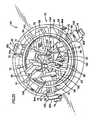
- the reel 110 when the recording tape cartridge is not in use, the reel 110 can rise upward (movable along the axial direction of the reel 110) against the urging force of the urging means such as the compression coil spring 116 or the like. Therefore, if the user carelessly pushes the floor wall 114 of the reel hub 112 upward due to the impact of a drop or the like, as shown in Fig. 24 , the braking member 130 may, in an inclined state, become anchored on the peripheral edge portion of the through hole 114A so as to tilt.
- the recording tape cartridge is loaded into a drive device in this state, not only will recording and playback not be possible, but also, breakage of the recording tape cartridge or malfunctioning of the drive device may be caused. Moreover, there is also the problem that, when the recording tape cartridge is not in use, because the reel can rotate, the recording tape may be adversely affected, such as wrinkles may form in the recording tape or the recording tape may be cut.
- a magnetic tape cassette having a reel rotatably accommodated in a cassette casing, said reel being movable away from the bottom wall of the cassette casing against the force of a spring in a direction parallel to the axis of the reel.
- the cassette is further provided with blocking means in the area of the reel hub of the reel, by means of which a movement of the reel in the direction parallel to the axis of the reel from its rest position into its drive position can be prevented.
- a pivotal bearing device for rotatably supporting the reel is provided, wherein the blocking means is formed by blocking levers pivotally connected to a bottom wall of the cup-like bearing device, and which project towards the bottom wall of the casing.
- An object of the present invention is to provide a recording tape cartridge in which, when a reel is in a state of being unable to rotate, movement of a braking member is restricted and movement of the reel is restricted.
- a recording tape cartridge comprising: a case; a reel rotatably accommodated in the case, a recording tape being wound around the reel, the reel having a hub and an engaging portion formed at a floor wall of the hub; a braking member provided so as to face the engaging portion and so as to be movable along an axial direction of the hub, the braking member being able to restrict rotation of the reel by engaging with the engaging portion, and being able to permit the rotation of the reel by canceling a state of engagement with the engaging portion; a part mounting portion formed at the case; a locking member mounted to the part mounting portion so as to be movable in a radial direction of the reel, the locking member restricting axial direction movement of the reel by being interposed between the reel and the case, and permitting movement of the reel by being pushed by the braking member and moving away from the reel; and an urging element urging the locking member in the radial direction of the reel, and
- a stabilizing portion jutting out from a corner portion of the locking member, the stabilizing portion able to generate a rotational moment which opposes a rotational moment which is generated at a corner portion of the locking member by pushing force of the braking member.
- the urging element has a plate spring having a base portion fixed at a center of the part mounting portion, and a leg piece spreading radially from the base portion.
- the locking member has an inclined surface which the leg piece abuts and which is for obtaining a component of force of force which pushes the locking member toward the case and which is generated by the urging force of the plate spring.
- arrow A the direction of loading a recording tape cartridge into a drive device
- arrow B denotes the leftward direction
- the front, back, left, right, top and bottom will be expressed by using these directions as reference.
- radial direction refers to the direction parallel to a direction heading radially outward from the axially central line of a reel accommodated in a case.
- the recording tape cartridge 10 has a case 12 which is formed substantially in the shape of a rectangular box.
- the case 12 is structured by an upper case 14 and a lower case 16, which are formed of a resin such as PC or the like, being joined together by ultrasonic welding or screws or the like in a state in which a peripheral wall 14B, which stands erect at the peripheral edge of a ceiling plate 14A, and a peripheral wall 16B, which stands erect at the peripheral edge of a floor plate 16A, abut one another.
- a single reel 40 is rotatably accommodated within the case 12.
- the reel 40 is structured such that a reel hub 42, which is shaped as a cylindrical tube having a floor and which structures the axially central portion of the reel 40, and an upper flange 44, which is provided at the top end portion of the reel hub 42, are formed integrally, and a lower flange 46 is ultrasonically welded to the bottom end portion of the reel hub 42.
- a recording tape T such as a magnetic tape or the like, which serves as an information recording/playback medium, is wound around the outer peripheral surface of the reel hub 42. The widthwise direction end portions of the wound recording tape T are held by the upper flange 44 and the lower flange 46.
- the opening 20 is formed so as to extend over respective portions of a front wall 12A and a left side wall 12B which are adjacent to the corner portion 12C.
- corner portion means the ridge line portion of intersection at a substantially right angle or an obtuse angle as seen in plan view, at the peripheral walls 14B, 16B of the substantially rectangular box shaped case 12. Accordingly, the corner portion 12C indicates the ridge line portion where the front wall 12A and the left side wall 12B intersect substantially at a right angle as seen in plan view.
- the leader tape 22 is a pulled-out member which a pull-out member (not illustrated) of a drive device engages in order to pull-out the recording tape T.
- a hole 22A, with which the pull-out member engages, is formed in a vicinity of the distal end of the leader tape 22.
- Jutting portions 22B, which respectively jut-out in the vertical direction, are formed at the top and bottom sides of the leader tape 22 at a region which is slightly more rearward than the distal end of the hole 22A.
- the leader tape 22 is held within the case 12 due to the jutting portions 22B being accommodated (inserted) in accommodating recesses 24 which are formed in the inner surface of the upper case 14 and the inner surface of the lower case 16, respectively.
- the opening 20 is closed by a door 30.
- the door 30 is formed in a substantial "L" shape as seen in plan view, of substantially the same configuration and size as the opening 20. It is preferable that the door 30 be molded from an olefin resin such as POM or the like. However, the door 30 may be molded from a resin such as PC or the like, or a metal such as SUS or the like.
- the upper case 14 side of the supporting shaft 26 is a hollow-cylindrical boss 26A, and the lower case 16 side thereof is a solid-cylindrical boss 26B.
- the supporting shaft 26 is structured by the distal end (top end) of the boss 26B at the lower case 16 side being fit into the boss 26A at the upper case 14 side. Accordingly, the diameter of the boss 26B is slightly smaller than the diameter of the boss 26A.
- Three, flat-plate-shaped rotating sliding portions 32 project in parallel from the inner surface of the door 30 in a vicinity of the right end portion (a position which is offset by a predetermined distance toward the left from the right end portion). These rotating sliding portions 32 respectively project from the top and bottom both end portions of the inner surface of the door 30, and from an intermediate portion which is slightly below the center. Through holes, in which the supporting shaft 26 is fit with play, are formed in the rotating sliding portions 32 respectively. Accordingly, the door 30 is supported rotatably by the supporting shaft 26 being inserted through the through holes.
- Annular convex portions 34 are formed around the through holes at the top surface of the rotating sliding portion 32 at the upper end portion, and at the bottom surface of the rotating sliding portion 32 of the lower end portion, respectively. Due to the annular convex portions 34 contacting the upper case 14 and the lower case 16, a clearance of about 0.3 mm to 0.5 mm is formed between a top end surface 30A of the door 30 and the upper case 14, and between a bottom end surface 30B of the door 30 and the lower case 16, respectively.
- Projecting portions 36 which are shaped, as seen in plan sectional view, in arc shapes which run along the peripheral surface of the supporting shaft 26, are formed at the inner surface of the door 30 between the rotating sliding portions 32.
- the supporting shaft 26 is inserted through a wound portion 28A of a torsion spring 28 which always urges the door 30 in the direction of closing the opening 20.
- the wound portion 28A of the torsion spring 28 is fit on and attached to the boss 26B whose diameter is small.
- One end portion side of the torsion spring 28 is anchored on a screw boss 38 of the case 12 (a screw boss which projects at the lower case 16).
- the other end portion side of the torsion spring 28 is anchored on the right side edge portion of the projecting portion 36.
- the reel 40 is molded of a resin material, and as described above, is structured by the reel hub 42 formed in the shape of a hollow cylinder having a floor, the upper flange 44 extending integrally from the upper end portion of the reel hub 42, and the lower flange 46 mounted by welding or the like to the lower end portion of the reel hub 42. Accordingly, the reel hub 42 and the lower flange 46 are molded by using resin materials which are compatible with one another, and can be easily welded together by ultrasonic waves or the like.
- a floor wall 48 is provided at the lower flange 46 side of the reel hub 42.
- a through hole 48A is formed in the axially central portion of the floor wall 48.
- a reel gear 50 is formed in an annular form at the bottom surface side of the floor wall 48. The reel 40 is pushed toward the lower case 16 by the urging force of a compression coil spring 78 which will be described later.
- the reel gear 50 is exposed from a circular gear opening 18 formed in the substantial center of the lower case 16, and meshes with a driving gear 102 provided at a rotating shaft 100 of a drive device, and transmits rotational power to the reel 40.
- An annular reel plate 52 formed of a magnetic material is integrally fixed by insert molding or the like at the radial direction inner side of the reel gear 50.
- the reel plate 52 is attracted by the magnetic force of an annular magnet 106 provided between the driving gear 102 and a releasing projection 104 which will be described later, such that axial offset between the reel 40 and the rotating shaft 100 is prevented, and such that the meshed-together state of the reel gear 50 and the driving gear 102 can be maintained.
- the reel 40 rotates integrally therewith within the case 12.
- An engaging gear 54 is formed in an annular form at the top surface side of the floor wall 48 of the reel hub 42, and can mesh with a braking gear 82 of a braking member 80.
- the braking member 80 is formed in the shape of a disc which is accommodated within the reel hub 42 so as to be movable upward and downward.
- the braking gear 82 is formed in an annular form at the outer peripheral portion of the bottom surface of the braking member 80.
- a plurality of (three in the present embodiment) plate-shaped guide portions 84, and a plurality of (three in the present embodiment) substantially rectangular-columnar engaging projections 86 stand erect at the top surface of the braking member 80.
- Abutment surfaces 86A whose radial direction inner sides are inclined at a predetermined angle (e.g., 45°), are formed at the engaging projections 86.
- a flat surface 80A is formed in an annular form at the top surface of the braking member 80, at the outer side of the guide portions 84 and the engaging projections 86.
- An operation projection 88 which is substantially solid-cylindrical and which can be inserted through the through hole 48A, projects at the center of the bottom surface of the braking member 80.
- the operation projection 88 can abut the releasing projection 104 which projects at the axially central portion of the rotating shaft 100 of the drive device (see Figs. 3 and 4 ).
- a part mounting portion 55 is provided at the substantial center of the inner surface of the ceiling plate 14A of the upper case 14.
- Three arc-shaped walls 62 are provided discontinuously at uniform intervals at the part mounting portion 55.
- Arc-shaped walls 64 whose heights are lower than those of the arc-shaped walls 62, are provided at the inner sides of the arc-shaped walls 62 in states of facing the arc-shaped walls 62.
- a pair of guide wall portions 68 are provided continuously with the arc-shaped walls 64, at the inner sides of the central portions of the arc-shaped walls 64.
- the guide wall portions 68 project higher than the arc-shaped walls 62, and are of sizes such that the plate-shaped guide portions 84, which are formed at the top surface of the braking member 80, can be inserted therein.
- a plurality of supporting ribs 66 (which will be described later) span radially between the arc-shaped walls 62 and the arc-shaped walls 64, and reinforce the arc-shaped walls 62 and the arc-shaped walls 64. Further, the gap between the arc-shaped walls 62 which are adjacent to one another is substantially the same as the gap between the arc-shaped walls 64 which are adjacent to one another. Accommodating portions 60 are formed by these gaps. Locking members 90 are slidably accommodated in the accommodating portions 60.
- the locking member 90 has a parallelepiped main body portion 92.
- a pair of concave portions 92C which extend along the longitudinal direction of the main body portion 92, are formed in the reverse surface of the main body portion 92 (the surface sliding along the ceiling plate 14A of the upper case 14).
- a cam portion 94 and an engaging wall 96 whose cross-sections are substantially trapezoidal, project in a state of opposing each other at the obverse of the main body portion 92 (the surface at the side opposite the surface sliding along the ceiling plate 14A of the upper case 14).
- An inclined surface 94B is formed at the outer surface of the cam portion 94. Toward the distal end side of the cam portion 94, the inclined surface 94B is inclined slightly inwardly at an angle ⁇ (see Fig. 10 ).
- An abutment surface 94A is provided at the inner surface of the distal end side of the cam portion 94. The abutment surface 94A can abut the abutment surface 86A of the substantially rectangular-columnar engaging projection 86 formed on the top surface of the braking member 80 (see Fig. 11B ).
- the abutment surface 94A is inclined at a predetermined angle, and the height thereof gradually decreases in the direction of moving away from the inclined surface 94B side of the cam portion 94.
- the engaging wall 96 is shorter than the cam portion 94.
- the cam portion 94 and the engaging wall 96 are separated from one another by more than at least the distance of separation between the arc-shaped wall 62 and the arc-shaped wall 64.
- a projecting portion 92D which is lower than the height of the supporting ribs 66 in the state in which the locking member 90 is accommodated in the accommodating portion 60, spans between the cam portion 94 and the engaging wall 96.
- the cam portion 94 and the engaging wall 96 are reinforced by the projecting portion 92D.
- An abutment surface 96A which is inclined at a predetermined angle, is formed at the outer surface of the distal end side of the engaging wall 96.
- the height of the abutment surface 96A decreases along the direction of moving away from the inner surface of the engaging wall 96.
- the configuration of the outer surface including this abutment surface 96A is an arc-shaped surface which, in plan view, matches the inner peripheral surface of the reel hub 42 (as will be described later).
- a step portion 96B juts out from the main body portion 92 at the proximal portion of the outer surface of the engaging wall 96.
- the thickness of the step portion 96B is substantially the same as a gap between the top surface of the upper flange 44 and the inner surface of the ceiling plate 14A in the state in which the lower flange 46 of the reel 40 abuts an annular rib 45 formed at the lower case 16, within the case 12.
- the step portion 96B and the engaging wall 96 can abut the top surface of the upper flange 44 of the reel 40 and the inner peripheral surface of the reel hub 42. Movement of the reel 40 is restricted in the state in which the step portion 96B and the engaging wall 96 abut the top surface of the upper flange 44 of the reel 40 and the inner peripheral surface of the reel hub 42 (i.e., in the state in which the locking members 90 are interposed between the inner surface of the ceiling plate 14A of the upper case 14 and the upper flange 44 of the reel 40).
- a plate spring 56 can be disposed at the central portion of the part mounting portion 55. As shown in Figs. 5 and 7 , the plate spring 56 is structured by a base portion 56A and leg pieces 56B. A hole 56C is formed in the base portion 56A, and can fit together with a boss 72 provided at the central portion of the part mounting portion 55. The leg pieces 56B spread radially at intervals of 120° from the base portion 56A. Each leg piece 56B is curved, from the base portion 56A to the distal end portion thereof, so as to delineate a large arc.
- Holding portions 70 project on lines connecting the end portions of the arc-shaped walls 62 with the end portions of the arc-shaped walls 64. As shown in Fig. 8 , in the state in which the locking member 90 is accommodated in the accommodating portion 60, the holding portions 70 are positioned at the transverse direction left and right of the locking member 90. Undercut portions 70A (amount of projection: approximately 0.3 mm), which are so-called undercut with respect to the direction of removal at the time of removing the upper case 14 from the mold which molds the upper case 14, are formed at the mutually opposing surfaces of the distal end portions of the holding portions 70. The shortest separation distance between the undercut portions 70A is more narrow than the width of the locking member 90.
- the holding portions 70 are elastically deformable. Therefore, when the locking member 90 is being made to be accommodated in the accommodating portion 60, the holding portions 70 are moved apart from one another such that undercut portions 70A do not get in the way. When the locking member 90 is accommodated in the accommodating portion 60, the undercut portions 70A hang over the surface of the main body portion 92 of the locking member 90, such that the locking member 90 is provisionally held.
- side walls 65 which are formed along lines connecting the end portions of the arc-shaped walls 62 with the end portions of the arc-shaped walls 64, span between the end portions of the guide wall portions 68 and the end portions of the arc-shaped walls 64.
- the side walls 65 reinforce the guide wall portions 68, and, in the state in which the locking members 90 are accommodated in the accommodating portions 60, restrict movement of the locking members 90.
- Stopper ribs 74 project at the outer sides of the arc-shaped walls 62, in correspondence with the accommodating portions 60.
- the locking members 90 can abut the stopper ribs 74. In the state in which the locking members 90 are accommodated in the accommodating portions 60, movement of the locking members 90 is restricted by and the locking members 90 are provisionally held by the stopper ribs 74 (see Fig. 9 ).
- the abutment surfaces 96A of the locking members 90 which are provisionally held by the stopper ribs 74, are arc-shaped surfaces which, in plan view, match the inner peripheral surface of the reel hub 42. Therefore, at the time of assembling the recording tape cartridge 10 (the time of placing the upper case 14 on the lower case 16), accompanying this action, it is easy for the abutment surfaces 96A to engage with the top edge portion of the reel hub 42. As shown in Fig. 3 , the abutment surfaces 96A are pressed by the top edge portion of the reel hub 42, and engaging wall 96 side end surfaces 92A of the main body portions 92 move away from the stopper ribs 74.
- an annular stopper 76 which is larger than the outer diameter of the arc-shaped walls 64 and smaller than the inner diameter of the arc-shaped walls 62, can be disposed between the arc-shaped walls 64 and the arc-shaped walls 62.
- the stopper 76 is fixed by welding or the like to the supporting ribs 66.
- the locking members 90 are completely prevented from being pulled out.
- the locking members 90 do not fall out from the upper case 14.
- the ability to assemble the plate spring 56 in is good because the plate spring 56 can be mounted even after the stopper 76 is welded on the supporting ribs 66 and the locking members 90 are completely prevented from coming out.
- the projecting portions 92D are lower than the heights of the supporting ribs 66 in the state in which the locking members 90 are accommodated in the accommodating portions 60. Therefore, as shown in Figs. 9 and 10 , in the state in which the stopper 76 is fixed to the supporting ribs 66, a gap C is formed between the stopper 76 and the projecting portions 92D, and the movable state of the locking members 90 is ensured.
- the stopper 76 also functions to press the locking members 90 at the time when the locking members 90 move within the accommodating portions 60, so as to work toward stability of movement of the locking members 90.
- the stopper 76 is for preventing the falling-down or flying-out or the like of the locking members 90. Therefore, the stopper 76 does not necessarily have to be ring-shaped, and may be a plate member spanning over the top surface of the locking member 90. Further, depending on the amount of projection of the undercut portions 70A of the holding portions 70, there are cases in which the locking members 90 can be completely prevented from coming out, and in this case, the stopper 76 or the like is not needed. Moreover, the holding portions 70 do not have to be molded integrally with the upper case 14. Therefore, by fixing the holding portions 70 to the upper case 14 as separate members for preventing the locking members 90 from coming out, the stopper 76 or the like becomes unnecessary.
- one end portion of the compression coil spring 78 can abut the stopper 76.
- the other end portion of the compression coil spring 78 abuts the flat surface 80A of the braking member 80. In this way, the reel 40 is urged toward the lower case 16 via the braking member 80.
- the braking member 80 is urged downward by the urging force of the compression coil spring 78, and the locking members 90 are urged toward the radial direction outer side of the reel 40 by the urging force of the plate spring 56.
- the engaging projection 104 abuts the operation projection 88, and the braking member 80 rises upward by a predetermined height against the urging force of the compression coil spring 78.
- the engaging projections 86 and the cam portions 94 abut one another, and the abutment surfaces 86A of the engaging projections 86 and the abutment surfaces 94A of the cam portions 94 slidingly contact one another.
- the pushing force of the plate spring 56 acts only in the radial direction (the horizontal direction), and does not act in the up-down direction (the vertical direction).
- the pushing force in the vertical direction is only the pushing force of the compression coil spring 78. Accordingly, even if the plate spring 56 is provided, the force needed to raise the braking member 80 is not increased.
- the door 30 closes the opening 20 due to the urging force of the torsion spring 28. Further, the leader tape 22 is disposed along the left side wall 12B due to the jutting portions 22B being accommodated (inserted) and held within the accommodating recesses 24.
- the braking member 80 When the recording tape cartridge 10 is not in use, as shown in Figs. 3 and 11A , the braking member 80 is urged downward by the compression coil spring 78. Namely, due to the urging force of the compression coil spring 78, the braking gear 82 of the braking member 80 meshes strongly with the engaging gear 54 in the reel hub 42, such that inadvertent rotation of the reel 40 is impeded.
- the locking members 90 are urged toward the radial direction outer side of the reel 40, the step portions 96B and the engaging walls 96 abut the top surface of the upper flange 44 of the reel 40 and the inner peripheral surface of the reel hub 42 respectively (the engaging walls 96 engage with the top edge portion of the reel hub 42), and vertical direction movement of the reel 40 is restricted.
- the recording tape cartridge 10 is loaded into a drive device (not illustrated). Namely, the recording tape cartridge 10 is inserted, from the front wall 12A side thereof, into a loading opening (not illustrated) of the drive device.
- an opening/closing member (not illustrated) of the drive device relatively approaches and abuts the right end portion of the door 30 (at the right side than the supporting shaft 26).
- the opening/closing member pushes the right end portion, the door 30 rotates around the supporting shaft 26 against the urging force of the torsion spring 28, such that the opening 20 is opened.
- a pull-out member (not illustrated) of the drive device approaches the opening 20 from the left side wall 12B side, and engages with the hole 22A of the leader tape 22. At this time, because the leader tape 22 is standing-by in a state of being adjacent to the left side wall 12B, the pull-out member can reliably engage the hole 22A.
- the rotating shaft 100 of the drive device enters in from the gear opening 19, and approaches the floor wall 48 of the reel 40. Namely, the releasing projection 104 pushes the operation projection 88, and the brake member 80 rises.
- the outer surface sides of the engaging walls 96 of the locking members 90 move away from the inner peripheral surface of the reel hub 42, and the cam portions 94 enter in (fall in) at the inner sides of the engaging projections 86.
- the step portions 96B of the locking members 90 are disposed at the inner side of the reel hub 42, and the engagement of the engaging walls 96 with the top edge portion of the reel hub 42 is released.
- the reel 40 becomes able to rotate and able to rise by a predetermined height within the case 12. Then, due to the rotating shaft 100 rising, the driving gear 102 meshes with the reel gear 50, and the reel plate 52 is attracted by the magnet 106.
- the reel 40 rises by a predetermined height within the case 12 and becomes able to rotate. Due to the driving gear 102, i.e., the reel 40, being driven to rotate synchronously with the take-up reel, the recording tape T is successively fed out to the drive device. Then, recording of data onto the recording tape T or playback of data recorded on the recording tape T is carried out by a recording/playback head (not illustrated) of the drive device.
- the driving gear 102 is rotated reversely, and the recording tape T is rewound onto the reel 40. Then, the leader tape 22 is disconnected from the take-up reel and is returned to the interior of the case 12 from the opening 20. Namely, the jutting portions 22B of the leader tape 22 are accommodated (inserted) in the accommodating recesses 24, and are held at predetermined positions within the case 12.
- the step portions 96B and the engaging walls 96 of the locking members 90 abut the top surface of the upper flange 44 of the reel 40 and the inner peripheral surface of the reel hub 42. In this way, when the recording tape cartridge 10 is not in use, vertical direction movement of the reel 40 is restricted.
- the recording tape cartridge 10 is discharged from the loading opening.
- the opening/closing member moves away from the right end portion of the door 30 accompanying this discharging operation, the door 30 rotates in the direction opposite to that described above around the supporting shaft 26 due to the urging force of the torsion spring 28, and closes the opening 20.
- the step portions 96B and the engaging walls 96 abut the top surface of the upper flange 44 of the reel 40 and the inner peripheral surface of the reel hub 42. In this way, when the recording tape cartridge 10 is not being used, movement of the reel 40 in the vertical direction is restricted.
- the part mounting portion 55 is provided at the central portion of the inner surface of the ceiling plate 14A of the upper case 14.
- the boss 72 is provided at the central portion of the part mounting portion 55, the plate spring 56 is attached to the boss 72, the leg pieces 56B of the plate spring 56 are made to abut the inclined surfaces 94B of the locking members 90, and the locking members 90 are urged from the central portion of the upper case 14.
- an accommodating rib 41 which accommodates the reel 40, and ribs (not illustrated) for reinforcing the upper case 14, and the like are provided at the peripheral wall 14B side of the upper case 14, and it is difficult to ensure space.
- the pair of concave portions 92C which are provided concavely along the longitudinal direction of the locking member 90, are formed in the reverse surface of the locking member 90 (the surface sliding along the ceiling plate 14A of the upper case 14).
- the surface area of sliding between the locking members 90 and the ceiling plate 14A of the upper case 14 can be made to be small. Therefore, the sliding resistance at the time when the locking members 90 slide on the ceiling plate 14A of the upper case 14 can be reduced, and the movement of the locking members 90 can be made to be smooth.
- convex portions 89 may be formed so as to project at the reverse surfaces of the locking members 90 as shown in Fig. 12 .
- concave portions or convex portions may be formed at the upper case 14, and the reverse surfaces of the locking members 90 may be subjected to a surface treatment to make the surface roughness thereof small, in order to reduce the sliding resistance between the locking members 90 and the ceiling plate 14A of the upper case 14.
- sliding sheets or the like may be fixed or coated or the like on the reverse surfaces of the locking members 90.
- the plate spring 56 is structured by the base portion 56A and the leg pieces 56B.
- the leg pieces 56B By making the leg pieces 56B widen radially from the base portion 56A, the single plate spring 56 suffices regardless of the number of the locking members 90. Therefore, at the time of assembly, it suffices to assemble in the single plate spring 56 regardless of the number of the locking members 90. Thus, assembly is facilitated, and workability improves.
- the leg pieces 56B are curved so as to delineate large arcs from the base portion 56A to the distal end portions thereof.
- the top and bottom directions of the plate spring 56 are thereby made clear. Therefore, there is no concern that the plate spring 56 will be assembled in upside-down.
- the leg pieces 56B abut the cam portions 94 of the locking members 90 and push the locking members 90 horizontally in directions of moving away from the boss 72.
- the abutment surfaces of the cam portions 94 which abutment surfaces the leg pieces 56B abut, are the inclined surface 94B (angle ⁇ ), and are inclined slightly inwardly along the directions toward the end portion sides of the cam portions 94. In this way, components of force Fy, which push the locking members 90 toward the upper case 14, can be generated, and the locking members 90 can be made to not move away from the upper case 14.
- a pushing force F of the plate spring 56 acts on the locking member 90.
- this pushing force F is broken down into a force which acts in the horizontal direction and a force which acts in the vertical direction with respect to the inclined surface 94B (so-called components of force)
- the pushing force F is reduced to a component of force F1 acting in the horizontal direction and a component of force F2 acting in the vertical direction.
- the component of force F2 is force which acts along the inclined surface 94B. Therefore, the component of force F2 is considered to not affect the locking member 90 in any way.
- the component of force F1 is broken down into forces which work in a horizontal direction Fx or a vertical direction Fy with respect to the locking member 90.
- the force in the vertical direction Fy is force pushing the locking member 90 toward the upper case 14, and the locking member 90 does not move away from the upper case 14.
- a coil spring 58 is used as the urging means which urges the locking member. Note that parts and structures which are equivalent to those described above are denoted by the same reference numerals, and description thereof is omitted. Further, the coil spring 58 is provided for each locking member. Accordingly, in this case, three of the coil springs 58 are provided.
- an outer surface of the cam portion 94 of a locking member 91 is a surface which is perpendicular with respect to the case 14.
- a fit-in portion 98 which has a substantially cross-shaped cross-section, projects out from the outer surface of the cam portion 94 along the longitudinal direction of the locking member 91.
- the fit-in portion 98 is fit-in one end portion of the coil spring 58.
- a straight portion 92B which juts out from the main body portion 92, is provided beneath the fit-in portion 98.
- the straight portion 92B supports the one end portion side of the coil spring 58 which is attached to the fit-in portion 98 (as will be described later).
- a substantially triangular-columnar anchor projection 73 projects at the central portion of the part mounting portion 55.
- a groove portion 73A is formed concavely in each side surface of the anchor projection 73 along the entire height thereof.
- the width of the groove portion 73A is greater deeper-in than at the entrance side thereof.
- the other end portion of the coil spring 58 is made to engage with the groove portion 73A. Because the width of the entrance side of the groove portion 73A is more narrow than the width at the deep side thereof, the other end portion of the coil spring 58 cannot easily get out of place with respect to the horizontal direction.
- the coil springs 58 and the locking members 91 can be prevented from flying out at the time of assembling-in the coil springs 58 and the locking members 91. Further, by making the straight portions 92B jut out from the main body portions 92 of the locking members 91, the centers of gravity of the locking members 91 can be made to be at the reverse surface sides (the case 14 sides) of the locking members 91, and the feeling of stability of the locking members 91 can be aimed for.
- the present invention is not limited to these springs, and a torsion spring or the like may be used.
- torsion springs 150 abut the anchor projection 73, and the other end portions of the torsion springs 150 abut locking members 152.
- the locking members 152 are urged toward the axial direction outer side of the reel 40 by the torsion springs 150.
- attachment bosses 154 which are shorter than the guide wall portions 68, are provided in vicinities of the distal end portions of the pairs of guide wall portions 68 of the part mounting portion 55.
- the axially central portions of the torsion springs 150 are attached to these attachment bosses 154. Further, because the one end portions of the torsion springs 150 are made to abut the anchor projection 73 of the part mounting portion 55, there is no need to form the groove portions 73A (see Fig. 14 ) in the anchor projection 73.
- an attachment rib 156 stands erect at the straight portion 92B.
- a cut-out portion 158 is formed in the side of the attachment rib 156 which side faces the anchor projection 73. The other end portion of the torsion spring 150 is anchored thereat.
- the leg pieces 56B of the plate spring 56 are curved so as to delineate large arcs from the base portion 56A to the distal end portions of the leg pieces 56B.
- the leg pieces 56B do not have to be curved, and may be formed by straight portions from the proximal portions of the leg pieces to the distal end portions thereof, although such a structure is not illustrated.
- a plate spring 162 may be provided for each locking member 160.
- the plate spring 162 is formed in a substantial V shape, and the both end portions thereof are set in the same plane and are oriented in directions of moving away from one another.
- anchor bosses 164 which are shorter than the guide wall portions 68, stand erect in vicinities of the distal end portions of the pairs of guide wall portions 68 of the part mounting portion 55.
- the anchor bosses 164 are formed such that gaps, which are slightly wider than the plate thickness of the plate springs 162, are provided between, on the one hand, the anchor bosses 164, and, on the other hand, the distal end portions of the side walls 65 which span between the end portions of the guide wall portions 68 and the end portions of the arc-shaped walls 64. The end portions of the plate springs 162 are fit into these gaps.
- the plate springs 162 are disposed such that the peak portions of the plate springs 162 are at the locking member 160 sides. In this way, the plate springs 162 abut the straight portions 92B of the locking members 160, and urge the locking members 160 toward the radial direction outer side of the reel 40.
- the braking gear 82 of the braking member 80 is pushed toward the engaging gear 54 of the reel hub 42 by the compression coil spring 78.
- the engaging gear 54 engage with the braking gear 82, and the present invention is not limited to the above-described structure.
- Figs. 19A through 19C the angles of inclination of abutment surfaces 95A of cam portions 95 of locking members 93 are changed.
- the abutment surfaces 95A of the cam portions 95 and the abutment surfaces 86A of the engaging projections 86 of the braking member 80 abut one another. Due to the urging force of the plate spring 56, a component of force which pushes the braking gear 82 toward the engaging gear 54 is applied.
- the compression coil spring 78 can thereby be rendered unnecessary. In this way, the number of parts can be reduced, and costs can be reduced.
- the above-described embodiment is structured such that the reel 40 is disposed at the substantially central portion of the case 12. However, the reel 40 does not have to be disposed at the central portion of the case 12.
- the recording tape cartridge 10 has the leader tape 22.
- the present invention is not limited by the configuration of the case 12, the structure for pulling-out the magnetic tape T (the structure of the leader member), the structure for opening and closing the opening 20, and the like.
- the recording tape cartridge 10 may be structured such that a small, solid cylindrical leader pin is attached as a leader member to the distal end of the magnetic tape T, or the recording tape cartridge 10 may be structured so as to have a shielding member which opens and closes the opening 20 (a sliding door which moves along a predetermined straight line or arc, or the like).
- the engaging portion which engages with the braking member 80 is the engaging gear 54.
- the configuration of the braking member may, of course, be changed in accordance with the configuration of the engaging portion.
- the above embodiment is structured such that the magnetic tape T is used as the recording tape.
- the present invention is not limited to the same. It suffices for the recording tape to be interpreted as an information recording/playback medium which is shaped as an elongated tape and on which information can be recorded and from which recorded information can be played back. It goes without saying that the recording tape cartridge relating to the present invention can be applied to recording tapes of any recording/playback systems.
Landscapes
- Packaging Of Annular Or Rod-Shaped Articles, Wearing Apparel, Cassettes, Or The Like (AREA)
Description
- The present invention relates to a recording tape cartridge rotatably accommodating a reel on which is wound a recording tape, such as a magnetic tape or the like, and to a plate spring.
- Conventionally, recording tape cartridges have been known in which a recording tape, such as a magnetic tape or the like, which is used as a data recording/playback medium for computers or the like, is wound on a single reel, and the reel is rotatably accommodated within a case formed of a synthetic resin. When the recording tape cartridge is in use (is loaded in a drive device), the reel of the recording tape cartridge can rotate within the case. When the recording tape cartridge is not in use (is not loaded in a drive device), the reel is locked so as to be unable to rotate within the case.
- Namely, the recording tape cartridge has a braking means in order for the reel to not rotate within the case when the recording tape cartridge is not in use. For example, a structure which makes a braking member, which cannot rotate with respect to the case, engage with the reel, or the like, can be thought of as the braking means.
- For example, as shown in
Fig. 24 , abraking member 130 is formed in the shape of a disc which is accommodated so as to be movable vertically within areel hub 112, which is shaped as a cylindrical tube having a floor, of areel 110. A pair ofengaging projections 134, which are substantially U-shaped as seen in plan view, stand erect at the top surface of thebraking member 130. A pair ofrotation restricting ribs 126, which are provided so as to extend downward from the inner surface of anupper case 122, are inserted in theengaging projections 134, such that thebraking member 130 cannot rotate with respect to thecase 120. - The
braking member 130 is usually urged toward afloor wall 114 of thereel hub 112 by an urging means such as acompression coil spring 116 or the like, and makes anannular braking gear 132, which is formed at the bottom surface of thebraking member 130, mesh with an annularengaging gear 118 which is formed at the top surface of thefloor wall 114 of thereel hub 112. Inadvertent rotation of thereel 110 is thereby impeded. - A substantially
cylindrical operation projection 136 projects at the axially central portion of the bottom surface of thebraking member 130. Theoperation projection 136 is inserted in athrough hole 114A, which is formed in the axially central portion of thefloor wall 114 of thereel hub 112, and faces agear opening 128 formed in a substantially central portion of alower case 124. Accordingly, when thereel 110 is to be made rotatable, the operation projection 136 (the braking member 130) is pushed upward, such that the meshing of thebraking gear 132 with theengaging gear 118 is cancelled (see, for example,USP No. 6,452,747 ). - However, in such a structure, when the recording tape cartridge is not in use, the
reel 110 can rise upward (movable along the axial direction of the reel 110) against the urging force of the urging means such as thecompression coil spring 116 or the like. Therefore, if the user carelessly pushes thefloor wall 114 of thereel hub 112 upward due to the impact of a drop or the like, as shown inFig. 24 , thebraking member 130 may, in an inclined state, become anchored on the peripheral edge portion of the throughhole 114A so as to tilt. - If the recording tape cartridge is loaded into a drive device in this state, not only will recording and playback not be possible, but also, breakage of the recording tape cartridge or malfunctioning of the drive device may be caused. Moreover, there is also the problem that, when the recording tape cartridge is not in use, because the reel can rotate, the recording tape may be adversely affected, such as wrinkles may form in the recording tape or the recording tape may be cut.
- From
WO 98/44506 A2 claim 1, there is known a magnetic tape cassette having a reel rotatably accommodated in a cassette casing, said reel being movable away from the bottom wall of the cassette casing against the force of a spring in a direction parallel to the axis of the reel. The cassette is further provided with blocking means in the area of the reel hub of the reel, by means of which a movement of the reel in the direction parallel to the axis of the reel from its rest position into its drive position can be prevented. Therein, a pivotal bearing device for rotatably supporting the reel is provided, wherein the blocking means is formed by blocking levers pivotally connected to a bottom wall of the cup-like bearing device, and which project towards the bottom wall of the casing. - An object of the present invention is to provide a recording tape cartridge in which, when a reel is in a state of being unable to rotate, movement of a braking member is restricted and movement of the reel is restricted.
- In order to achieve the above object, in accordance with one aspect of the present invention, there is provided a recording tape cartridge comprising: a case; a reel rotatably accommodated in the case, a recording tape being wound around the reel, the reel having a hub and an engaging portion formed at a floor wall of the hub; a braking member provided so as to face the engaging portion and so as to be movable along an axial direction of the hub, the braking member being able to restrict rotation of the reel by engaging with the engaging portion, and being able to permit the rotation of the reel by canceling a state of engagement with the engaging portion; a part mounting portion formed at the case; a locking member mounted to the part mounting portion so as to be movable in a radial direction of the reel, the locking member restricting axial direction movement of the reel by being interposed between the reel and the case, and permitting movement of the reel by being pushed by the braking member and moving away from the reel; and an urging element urging the locking member in the radial direction of the reel, and interposed between the reel and the case, and restricting the axial direction movement of the reel, wherein a plurality of convex portions is provided at sliding surfaces of the locking member and the case.
- In accordance with another aspect of the present invention, there is provided a stabilizing portion jutting out from a corner portion of the locking member, the stabilizing portion able to generate a rotational moment which opposes a rotational moment which is generated at a corner portion of the locking member by pushing force of the braking member.
- In accordance with still another aspect of the present invention, the urging element has a plate spring having a base portion fixed at a center of the part mounting portion, and a leg piece spreading radially from the base portion.
- In accordance with yet another aspect of the present invention, the locking member has an inclined surface which the leg piece abuts and which is for obtaining a component of force of force which pushes the locking member toward the case and which is generated by the urging force of the plate spring.
- Other objects, features and advantages of the present invention will be apparent to those skilled in the art from the explanation of the preferred embodiment of the present invention illustrated in the appended drawings, and from the appended claims.
-
-
Fig. 1 is a perspective view showing the exterior of a recording tape cartridge relating to an embodiment of the present invention. -
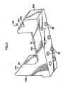
Fig. 2 is an exploded perspective view in a state in which the recording tape cartridge relating to the embodiment of the present invention is turned upside-down. -
Fig. 3 is a sectional view at a time when rotation of a reel is restricted in the recording tape cartridge relating to the embodiment of the present invention. -
Fig. 4 is a sectional view at a time when rotation of the reel is permitted the recording tape cartridge relating to the embodiment of the present invention. -
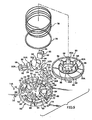
Fig. 5 is an exploded perspective view showing a braking member, parts mounted in a part mounting portion, and the like of the recording tape cartridge relating to the embodiment of the present invention. -
Fig. 6 is a perspective view as seen from a reverse surface side of a locking member structuring the recording tape cartridge relating to the embodiment of the present invention. -
Fig. 7 is an exploded perspective view showing main portions ofFig. 5 . -
Fig. 8 is a sectional view showing the relationship between holding portions and the locking member structuring the recording tape cartridge relating to the embodiment of the present invention. -
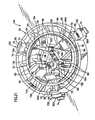
Fig. 9 is a perspective view showing a state in which the respective parts ofFig. 5 are mounted to the part mounting portion. -
Fig. 10 is a sectional view showing the relationship between a supporting rib and a stopper structuring the recording tape cartridge relating to the embodiment of the present invention. -
Figs. 11A through 11C are operational diagrams showing the relationship between a rotating shaft of a drive device and the recording tape cartridge relating to the embodiment of the present invention. -
Fig. 12 is a perspective view as seen from a reverse surface side of a modified example of a locking member structuring the recording tape cartridge relating to the embodiment of the present invention. -
Fig. 13 is an explanatory diagram showing the relationship between a plate spring and the locking member structuring the recording tape cartridge relating to the embodiment of the present invention. -
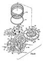
Fig. 14 is an exploded perspective view showing the braking member, a modified example of parts mounted within the part mounting portion, and the like of the recording tape cartridge relating to the embodiment of the present invention. -
Fig. 15 is an exploded perspective view of main portions ofFig. 14 . -
Fig. 16 is a perspective view showing a state in which the respective parts ofFig. 14 are mounted in the part mounting portion. -
Figs. 17A through 17C are operational diagrams showing the modified example of the recording tape cartridge relating to the embodiment of the present invention. -
Fig. 18 is an explanatory diagram showing a relationship between the braking member and the locking member structuring the recording tape cartridge relating to the embodiment of the present invention. -
Figs. 19A through 19C are operational diagrams showing another modified example of the recording tape cartridge relating to the embodiment of the present invention. -
Fig. 20 is an exploded perspective view showing the braking member, yet another modified example of parts mounted in the part mounting portion, and the like of the recording tape cartridge relating to the embodiment of the present invention. -
Fig. 21 is a perspective view showing a state in which the respective parts ofFig. 20 are mounted to the part mounting portion. -
Fig. 22 is an exploded perspective view showing the braking member, still yet another modified example of parts mounted in the part mounting portion, and the like of the recording tape cartridge relating to the embodiment of the present invention. -
Fig. 23 is a perspective view showing a state in which the respective parts ofFig. 22 are mounted in the part mounting portion. -
Fig. 24 is a sectional view showing a conventional recording tape cartridge. - An embodiment of the present invention will be described in detail hereinafter on the basis of the drawings. Note that, for convenience of explanation, the direction of loading a recording tape cartridge into a drive device is denoted by arrow A, and this direction is the front direction. Further, arrow B denotes the leftward direction, and the front, back, left, right, top and bottom will be expressed by using these directions as reference. When the term "radial direction" is used hereinafter, it refers to the direction parallel to a direction heading radially outward from the axially central line of a reel accommodated in a case.
- As shown in
Figs. 1 and2 (note thatFig. 2 is an exploded perspective view in which arecording tape cartridge 10 is turned upside down), therecording tape cartridge 10 has acase 12 which is formed substantially in the shape of a rectangular box. Thecase 12 is structured by anupper case 14 and alower case 16, which are formed of a resin such as PC or the like, being joined together by ultrasonic welding or screws or the like in a state in which a peripheral wall 14B, which stands erect at the peripheral edge of aceiling plate 14A, and aperipheral wall 16B, which stands erect at the peripheral edge of afloor plate 16A, abut one another. - A
single reel 40 is rotatably accommodated within thecase 12. As shown inFigs. 2 through 4 , thereel 40 is structured such that areel hub 42, which is shaped as a cylindrical tube having a floor and which structures the axially central portion of thereel 40, and anupper flange 44, which is provided at the top end portion of thereel hub 42, are formed integrally, and alower flange 46 is ultrasonically welded to the bottom end portion of thereel hub 42. A recording tape T, such as a magnetic tape or the like, which serves as an information recording/playback medium, is wound around the outer peripheral surface of thereel hub 42. The widthwise direction end portions of the wound recording tape T are held by theupper flange 44 and thelower flange 46. - As shown in
Fig. 1 , anopening 20, which is for the pulling-out to the exterior of the recording tape T wound on thereel 40, is formed in a vicinity of a frontleft corner portion 12C of therecording tape cartridge 10. Namely, theopening 20 is formed so as to extend over respective portions of afront wall 12A and a left side wall 12B which are adjacent to thecorner portion 12C. Aleader tape 22, which is fixed to an end portion of the recording tape T and is disposed along the left side wall 12B, is pulled-out from theopening 20. - Here, "corner portion" means the ridge line portion of intersection at a substantially right angle or an obtuse angle as seen in plan view, at the
peripheral walls 14B, 16B of the substantially rectangular box shapedcase 12. Accordingly, thecorner portion 12C indicates the ridge line portion where thefront wall 12A and the left side wall 12B intersect substantially at a right angle as seen in plan view. - The
leader tape 22 is a pulled-out member which a pull-out member (not illustrated) of a drive device engages in order to pull-out the recording tape T. Ahole 22A, with which the pull-out member engages, is formed in a vicinity of the distal end of theleader tape 22. Juttingportions 22B, which respectively jut-out in the vertical direction, are formed at the top and bottom sides of theleader tape 22 at a region which is slightly more rearward than the distal end of thehole 22A. Theleader tape 22 is held within thecase 12 due to the juttingportions 22B being accommodated (inserted) inaccommodating recesses 24 which are formed in the inner surface of theupper case 14 and the inner surface of thelower case 16, respectively. - When the
recording tape cartridge 10 is not in use, theopening 20 is closed by adoor 30. Thedoor 30 is formed in a substantial "L" shape as seen in plan view, of substantially the same configuration and size as theopening 20. It is preferable that thedoor 30 be molded from an olefin resin such as POM or the like. However, thedoor 30 may be molded from a resin such as PC or the like, or a metal such as SUS or the like. - A supporting
shaft 26, which is the fulcrum of rotation of thedoor 30, projects at thefront wall 12A sides of theupper case 14 and thelower case 16, respectively. Theupper case 14 side of the supportingshaft 26 is a hollow-cylindrical boss 26A, and thelower case 16 side thereof is a solid-cylindrical boss 26B. The supportingshaft 26 is structured by the distal end (top end) of theboss 26B at thelower case 16 side being fit into theboss 26A at theupper case 14 side. Accordingly, the diameter of theboss 26B is slightly smaller than the diameter of theboss 26A. - Three, flat-plate-shaped rotating sliding
portions 32 project in parallel from the inner surface of thedoor 30 in a vicinity of the right end portion (a position which is offset by a predetermined distance toward the left from the right end portion). These rotating slidingportions 32 respectively project from the top and bottom both end portions of the inner surface of thedoor 30, and from an intermediate portion which is slightly below the center. Through holes, in which the supportingshaft 26 is fit with play, are formed in the rotating slidingportions 32 respectively. Accordingly, thedoor 30 is supported rotatably by the supportingshaft 26 being inserted through the through holes. - Annular
convex portions 34 are formed around the through holes at the top surface of the rotating slidingportion 32 at the upper end portion, and at the bottom surface of the rotating slidingportion 32 of the lower end portion, respectively. Due to the annularconvex portions 34 contacting theupper case 14 and thelower case 16, a clearance of about 0.3 mm to 0.5 mm is formed between atop end surface 30A of thedoor 30 and theupper case 14, and between abottom end surface 30B of thedoor 30 and thelower case 16, respectively. - Projecting
portions 36, which are shaped, as seen in plan sectional view, in arc shapes which run along the peripheral surface of the supportingshaft 26, are formed at the inner surface of thedoor 30 between the rotating slidingportions 32. - The supporting
shaft 26 is inserted through awound portion 28A of atorsion spring 28 which always urges thedoor 30 in the direction of closing theopening 20. Namely, in the state of being held between the rotating slidingportion 32 at the lower end portion and the rotating slidingportion 32 at the intermediate portion, thewound portion 28A of thetorsion spring 28 is fit on and attached to theboss 26B whose diameter is small. One end portion side of thetorsion spring 28 is anchored on ascrew boss 38 of the case 12 (a screw boss which projects at the lower case 16). The other end portion side of thetorsion spring 28 is anchored on the right side edge portion of the projectingportion 36. - The
reel 40 is molded of a resin material, and as described above, is structured by thereel hub 42 formed in the shape of a hollow cylinder having a floor, theupper flange 44 extending integrally from the upper end portion of thereel hub 42, and thelower flange 46 mounted by welding or the like to the lower end portion of thereel hub 42. Accordingly, thereel hub 42 and thelower flange 46 are molded by using resin materials which are compatible with one another, and can be easily welded together by ultrasonic waves or the like. - As shown in
Figs. 2 through 4 , afloor wall 48 is provided at thelower flange 46 side of thereel hub 42. A throughhole 48A is formed in the axially central portion of thefloor wall 48. Areel gear 50 is formed in an annular form at the bottom surface side of thefloor wall 48. Thereel 40 is pushed toward thelower case 16 by the urging force of acompression coil spring 78 which will be described later. - In this state, the
reel gear 50 is exposed from acircular gear opening 18 formed in the substantial center of thelower case 16, and meshes with adriving gear 102 provided at arotating shaft 100 of a drive device, and transmits rotational power to thereel 40. - An
annular reel plate 52 formed of a magnetic material is integrally fixed by insert molding or the like at the radial direction inner side of thereel gear 50. In the state in which thedriving gear 102 and thereel gear 50 are completely meshed together, thereel plate 52 is attracted by the magnetic force of anannular magnet 106 provided between the drivinggear 102 and a releasingprojection 104 which will be described later, such that axial offset between thereel 40 and therotating shaft 100 is prevented, and such that the meshed-together state of thereel gear 50 and thedriving gear 102 can be maintained. In accordance with such a structure, when therotating shaft 100 rotates around its own axis, thereel 40 rotates integrally therewith within thecase 12. - An
engaging gear 54 is formed in an annular form at the top surface side of thefloor wall 48 of thereel hub 42, and can mesh with abraking gear 82 of a brakingmember 80. As shown inFigs. 4 and5 , the brakingmember 80 is formed in the shape of a disc which is accommodated within thereel hub 42 so as to be movable upward and downward. Thebraking gear 82 is formed in an annular form at the outer peripheral portion of the bottom surface of the brakingmember 80. - A plurality of (three in the present embodiment) plate-shaped
guide portions 84, and a plurality of (three in the present embodiment) substantially rectangular-columnarengaging projections 86 stand erect at the top surface of the brakingmember 80. Abutment surfaces 86A, whose radial direction inner sides are inclined at a predetermined angle (e.g., 45°), are formed at the engagingprojections 86. - A
flat surface 80A is formed in an annular form at the top surface of the brakingmember 80, at the outer side of theguide portions 84 and the engagingprojections 86. Anoperation projection 88, which is substantially solid-cylindrical and which can be inserted through the throughhole 48A, projects at the center of the bottom surface of the brakingmember 80. Theoperation projection 88 can abut the releasingprojection 104 which projects at the axially central portion of therotating shaft 100 of the drive device (seeFigs. 3 and4 ). - As shown in
Figs. 4 and5 , apart mounting portion 55 is provided at the substantial center of the inner surface of theceiling plate 14A of theupper case 14. Three arc-shapedwalls 62 are provided discontinuously at uniform intervals at thepart mounting portion 55. Arc-shapedwalls 64, whose heights are lower than those of the arc-shapedwalls 62, are provided at the inner sides of the arc-shapedwalls 62 in states of facing the arc-shapedwalls 62. A pair ofguide wall portions 68 are provided continuously with the arc-shapedwalls 64, at the inner sides of the central portions of the arc-shapedwalls 64. Theguide wall portions 68 project higher than the arc-shapedwalls 62, and are of sizes such that the plate-shapedguide portions 84, which are formed at the top surface of the brakingmember 80, can be inserted therein. - A plurality of supporting ribs 66 (which will be described later) span radially between the arc-shaped
walls 62 and the arc-shapedwalls 64, and reinforce the arc-shapedwalls 62 and the arc-shapedwalls 64. Further, the gap between the arc-shapedwalls 62 which are adjacent to one another is substantially the same as the gap between the arc-shapedwalls 64 which are adjacent to one another. Accommodatingportions 60 are formed by these gaps. Lockingmembers 90 are slidably accommodated in theaccommodating portions 60. - As shown in
Figs. 6 and7 , the lockingmember 90 has a parallelepipedmain body portion 92. A pair ofconcave portions 92C, which extend along the longitudinal direction of themain body portion 92, are formed in the reverse surface of the main body portion 92 (the surface sliding along theceiling plate 14A of the upper case 14). Further, acam portion 94 and an engagingwall 96, whose cross-sections are substantially trapezoidal, project in a state of opposing each other at the obverse of the main body portion 92 (the surface at the side opposite the surface sliding along theceiling plate 14A of the upper case 14). - An
inclined surface 94B is formed at the outer surface of thecam portion 94. Toward the distal end side of thecam portion 94, theinclined surface 94B is inclined slightly inwardly at an angle θ (seeFig. 10 ). Anabutment surface 94A is provided at the inner surface of the distal end side of thecam portion 94. Theabutment surface 94A can abut theabutment surface 86A of the substantially rectangular-columnar engaging projection 86 formed on the top surface of the braking member 80 (seeFig. 11B ). Theabutment surface 94A is inclined at a predetermined angle, and the height thereof gradually decreases in the direction of moving away from theinclined surface 94B side of thecam portion 94. - The engaging
wall 96 is shorter than thecam portion 94. Thecam portion 94 and the engagingwall 96 are separated from one another by more than at least the distance of separation between the arc-shapedwall 62 and the arc-shapedwall 64. A projectingportion 92D, which is lower than the height of the supportingribs 66 in the state in which the lockingmember 90 is accommodated in theaccommodating portion 60, spans between thecam portion 94 and the engagingwall 96. Thecam portion 94 and the engagingwall 96 are reinforced by the projectingportion 92D. - An
abutment surface 96A, which is inclined at a predetermined angle, is formed at the outer surface of the distal end side of the engagingwall 96. The height of theabutment surface 96A decreases along the direction of moving away from the inner surface of the engagingwall 96. The configuration of the outer surface including thisabutment surface 96A is an arc-shaped surface which, in plan view, matches the inner peripheral surface of the reel hub 42 (as will be described later). - A
step portion 96B juts out from themain body portion 92 at the proximal portion of the outer surface of the engagingwall 96. As shown inFig. 3 , the thickness of thestep portion 96B is substantially the same as a gap between the top surface of theupper flange 44 and the inner surface of theceiling plate 14A in the state in which thelower flange 46 of thereel 40 abuts anannular rib 45 formed at thelower case 16, within thecase 12. - The
step portion 96B and the engagingwall 96 can abut the top surface of theupper flange 44 of thereel 40 and the inner peripheral surface of thereel hub 42. Movement of thereel 40 is restricted in the state in which thestep portion 96B and the engagingwall 96 abut the top surface of theupper flange 44 of thereel 40 and the inner peripheral surface of the reel hub 42 (i.e., in the state in which thelocking members 90 are interposed between the inner surface of theceiling plate 14A of theupper case 14 and theupper flange 44 of the reel 40). - A
plate spring 56 can be disposed at the central portion of thepart mounting portion 55. As shown inFigs. 5 and7 , theplate spring 56 is structured by abase portion 56A andleg pieces 56B. Ahole 56C is formed in thebase portion 56A, and can fit together with aboss 72 provided at the central portion of thepart mounting portion 55. Theleg pieces 56B spread radially at intervals of 120° from thebase portion 56A. Eachleg piece 56B is curved, from thebase portion 56A to the distal end portion thereof, so as to delineate a large arc. - In the state in which the
hole 56C of theplate spring 56 is fit together with theboss 72, the distal end portion of theboss 72 is caulked, such that theplate spring 56 cannot be pulled off of theboss 72. In this state, theleg pieces 56B can abut theinclined surfaces 94B of thecam portions 94 of the lockingmembers 90 which are accommodated in theaccommodating portions 60. - Holding
portions 70 project on lines connecting the end portions of the arc-shapedwalls 62 with the end portions of the arc-shapedwalls 64. As shown inFig. 8 , in the state in which the lockingmember 90 is accommodated in theaccommodating portion 60, the holdingportions 70 are positioned at the transverse direction left and right of the lockingmember 90. Undercutportions 70A (amount of projection: approximately 0.3 mm), which are so-called undercut with respect to the direction of removal at the time of removing theupper case 14 from the mold which molds theupper case 14, are formed at the mutually opposing surfaces of the distal end portions of the holdingportions 70. The shortest separation distance between theundercut portions 70A is more narrow than the width of the lockingmember 90. - The holding
portions 70 are elastically deformable. Therefore, when the lockingmember 90 is being made to be accommodated in theaccommodating portion 60, the holdingportions 70 are moved apart from one another such that undercutportions 70A do not get in the way. When the lockingmember 90 is accommodated in theaccommodating portion 60, theundercut portions 70A hang over the surface of themain body portion 92 of the lockingmember 90, such that the lockingmember 90 is provisionally held. - On the other hand, as shown in
Fig. 5 ,side walls 65, which are formed along lines connecting the end portions of the arc-shapedwalls 62 with the end portions of the arc-shapedwalls 64, span between the end portions of theguide wall portions 68 and the end portions of the arc-shapedwalls 64. Theside walls 65 reinforce theguide wall portions 68, and, in the state in which thelocking members 90 are accommodated in theaccommodating portions 60, restrict movement of the lockingmembers 90. -
Stopper ribs 74 project at the outer sides of the arc-shapedwalls 62, in correspondence with theaccommodating portions 60. The lockingmembers 90 can abut thestopper ribs 74. In the state in which thelocking members 90 are accommodated in theaccommodating portions 60, movement of the lockingmembers 90 is restricted by and the lockingmembers 90 are provisionally held by the stopper ribs 74 (seeFig. 9 ). - The abutment surfaces 96A of the locking
members 90, which are provisionally held by thestopper ribs 74, are arc-shaped surfaces which, in plan view, match the inner peripheral surface of thereel hub 42. Therefore, at the time of assembling the recording tape cartridge 10 (the time of placing theupper case 14 on the lower case 16), accompanying this action, it is easy for the abutment surfaces 96A to engage with the top edge portion of thereel hub 42. As shown inFig. 3 , the abutment surfaces 96A are pressed by the top edge portion of thereel hub 42, and engagingwall 96 side end surfaces 92A of themain body portions 92 move away from thestopper ribs 74. - As shown in
Figs. 5 and9 , anannular stopper 76, which is larger than the outer diameter of the arc-shapedwalls 64 and smaller than the inner diameter of the arc-shapedwalls 62, can be disposed between the arc-shapedwalls 64 and the arc-shapedwalls 62. In the state in which thelocking members 90 are accommodated in theaccommodating portions 60, thestopper 76 is fixed by welding or the like to the supportingribs 66. - In this way, the locking
members 90 are completely prevented from being pulled out. When theupper case 14 is placed on thelower case 16, the lockingmembers 90 do not fall out from theupper case 14. Here, the ability to assemble theplate spring 56 in is good because theplate spring 56 can be mounted even after thestopper 76 is welded on the supportingribs 66 and the lockingmembers 90 are completely prevented from coming out. - The projecting
portions 92D are lower than the heights of the supportingribs 66 in the state in which thelocking members 90 are accommodated in theaccommodating portions 60. Therefore, as shown inFigs. 9 and10 , in the state in which thestopper 76 is fixed to the supportingribs 66, a gap C is formed between thestopper 76 and the projectingportions 92D, and the movable state of the lockingmembers 90 is ensured. Thestopper 76 also functions to press the lockingmembers 90 at the time when the lockingmembers 90 move within theaccommodating portions 60, so as to work toward stability of movement of the lockingmembers 90. - The
stopper 76 is for preventing the falling-down or flying-out or the like of the lockingmembers 90. Therefore, thestopper 76 does not necessarily have to be ring-shaped, and may be a plate member spanning over the top surface of the lockingmember 90. Further, depending on the amount of projection of theundercut portions 70A of the holdingportions 70, there are cases in which thelocking members 90 can be completely prevented from coming out, and in this case, thestopper 76 or the like is not needed. Moreover, the holdingportions 70 do not have to be molded integrally with theupper case 14. Therefore, by fixing the holdingportions 70 to theupper case 14 as separate members for preventing the lockingmembers 90 from coming out, thestopper 76 or the like becomes unnecessary. - As shown in
Fig. 3 , one end portion of thecompression coil spring 78 can abut thestopper 76. The other end portion of thecompression coil spring 78 abuts theflat surface 80A of the brakingmember 80. In this way, thereel 40 is urged toward thelower case 16 via the brakingmember 80. - In accordance with the above-described structure, as shown in
Fig. 11A , when therecording tape cartridge 10 is not in use, the brakingmember 80 is urged downward by the urging force of thecompression coil spring 78, and the lockingmembers 90 are urged toward the radial direction outer side of thereel 40 by the urging force of theplate spring 56. - At this time, due to the
guide portions 84 which are inserted in theguide wall portions 68, rotation of the brakingmember 80 with respect to thecase 12 is impeded, and theengaging gear 54 within thereel hub 42 strongly meshes with thebraking gear 82 of the brakingmember 80. Inadvertent rotation of thereel 40 is thereby impeded. - In the state in which the
lower flange 46 of thereel 40 abuts theannular rib 45 formed at thelower case 16, thestep portions 96B and engagingwalls 96 of the lockingmembers 90 abut the top surface of theupper flange 44 of thereel 40 and the inner peripheral surface of thereel hub 42. Vertical direction movement of thereel 40 is thereby restricted when therecording tape cartridge 10 is not in use. - On the other hand, when the
recording tape cartridge 10 is used, as shown inFig. 11B , the engagingprojection 104 abuts theoperation projection 88, and the brakingmember 80 rises upward by a predetermined height against the urging force of thecompression coil spring 78. In this way, the engagingprojections 86 and thecam portions 94 abut one another, and the abutment surfaces 86A of the engagingprojections 86 and the abutment surfaces 94A of thecam portions 94 slidingly contact one another. - Here, because the abutment surfaces 94A of the locking
members 90 and the abutment surfaces 86A of the engagingprojections 86 are inclined, the forces, which are transmitted from the abutment surfaces 86A of the engagingprojections 86 and work along the axial direction of thehub 42 of thereel 40, are converted into forces which move the lockingmembers 90 in the horizontal direction. The lockingmembers 90 move inwardly in the radial direction on theupper case 14 against the urging forces of theleg pieces 56B. - As shown in
Fig. 11C , when thecam portions 94 enter in at the inner surface sides of the engagingprojections 86, the states of abutment of thecam portions 94 and the engagingprojections 86 are cancelled. In this way, the states of engagement between, on the one hand, the lockingmembers 90, and, on the other hand, the brakingmember 80 and thereel 40, are cancelled. Thereel 40 becomes able to rotate and to rise by a predetermined height within thecase 12. - Due to the
cam portions 94 entering in at the inner surface sides of the engagingprojections 86, the pushing forces (urging forces) by which thelocking members 90 are pushed by theplate spring 56 are received at the inner surfaces of the engagingprojections 86 via the outer surfaces of thecam portions 94. In this way, due to the states of abutment of the abutment surfaces 86A of the engagingprojections 86 and the abutment surfaces 94A of thecam portions 94 being cancelled, when the brakingmember 80 rises up, the pushing force of theplate spring 56 is not transmitted in the vertical direction of the engagingprojections 86. - Namely, when the
recording tape cartridge 10 is being used, the pushing force of theplate spring 56 acts only in the radial direction (the horizontal direction), and does not act in the up-down direction (the vertical direction). The pushing force in the vertical direction is only the pushing force of thecompression coil spring 78. Accordingly, even if theplate spring 56 is provided, the force needed to raise the brakingmember 80 is not increased. - Next, operation of the
recording tape cartridge 10, which is structured as described above, will be described. - As shown in
Fig. 1 , when therecording tape cartridge 10 is not being used (is not loaded in a drive device), thedoor 30 closes theopening 20 due to the urging force of thetorsion spring 28. Further, theleader tape 22 is disposed along the left side wall 12B due to the juttingportions 22B being accommodated (inserted) and held within the accommodating recesses 24. - When the
recording tape cartridge 10 is not in use, as shown inFigs. 3 and11A , the brakingmember 80 is urged downward by thecompression coil spring 78. Namely, due to the urging force of thecompression coil spring 78, thebraking gear 82 of the brakingmember 80 meshes strongly with the engaginggear 54 in thereel hub 42, such that inadvertent rotation of thereel 40 is impeded. - Due to the urging force of the
plate spring 56, the lockingmembers 90 are urged toward the radial direction outer side of thereel 40, thestep portions 96B and theengaging walls 96 abut the top surface of theupper flange 44 of thereel 40 and the inner peripheral surface of thereel hub 42 respectively (the engagingwalls 96 engage with the top edge portion of the reel hub 42), and vertical direction movement of thereel 40 is restricted. - On the other hand, when data is to be recorded on the recording tape T (see
Fig. 3 ) of therecording tape cartridge 10 shown inFig. 1 , or when data recorded on the recording tape T of therecording tape cartridge 10 is to be played back, therecording tape cartridge 10 is loaded into a drive device (not illustrated). Namely, therecording tape cartridge 10 is inserted, from thefront wall 12A side thereof, into a loading opening (not illustrated) of the drive device. - Accompanying this loading, an opening/closing member (not illustrated) of the drive device relatively approaches and abuts the right end portion of the door 30 (at the right side than the supporting shaft 26). When the opening/closing member pushes the right end portion, the
door 30 rotates around the supportingshaft 26 against the urging force of thetorsion spring 28, such that theopening 20 is opened. - When the
door 30 rotates and theopening 20 is opened, a pull-out member (not illustrated) of the drive device approaches theopening 20 from the left side wall 12B side, and engages with thehole 22A of theleader tape 22. At this time, because theleader tape 22 is standing-by in a state of being adjacent to the left side wall 12B, the pull-out member can reliably engage thehole 22A. - When the pull-out member engages the
hole 22A in this way, due to the pull-out member moving away from theopening 20, theleader tape 22 is pulled-out from the interior of thecase 12. Then, theleader tape 22 which has been pulled-out from the interior of thecase 12 is wound onto a take-up reel (not illustrated) of the drive device. - Next, as shown in
Figs. 3 ,11A, and 11B , therotating shaft 100 of the drive device enters in from the gear opening 19, and approaches thefloor wall 48 of thereel 40. Namely, the releasingprojection 104 pushes theoperation projection 88, and thebrake member 80 rises. - In this way, the meshing-together of the
engaging gear 54 and thebraking gear 82 is cancelled, and the engagingprojections 86 abut thecam portions 94 of the lockingmembers 90 and push thecam portions 94 along the axial direction of thehub 42 of thereel 40. The forces, which are transmitted from the abutment surfaces 86A of the engagingprojections 86, are converted into forces which move the lockingmembers 90 in the horizontal direction. Therefore, the lockingmembers 90 move toward the radial direction inner side of thereel 40 on theupper case 14 against the urging force of theplate spring 56. - Namely, as shown in
Figs. 4 and11C , the outer surface sides of theengaging walls 96 of the lockingmembers 90 move away from the inner peripheral surface of thereel hub 42, and thecam portions 94 enter in (fall in) at the inner sides of the engagingprojections 86. In this way, thestep portions 96B of the lockingmembers 90 are disposed at the inner side of thereel hub 42, and the engagement of theengaging walls 96 with the top edge portion of thereel hub 42 is released. - In this way, the
reel 40 becomes able to rotate and able to rise by a predetermined height within thecase 12. Then, due to therotating shaft 100 rising, thedriving gear 102 meshes with thereel gear 50, and thereel plate 52 is attracted by themagnet 106. - When the
driving gear 102 meshes with thereel gear 50 in this way, thereel 40 rises by a predetermined height within thecase 12 and becomes able to rotate. Due to thedriving gear 102, i.e., thereel 40, being driven to rotate synchronously with the take-up reel, the recording tape T is successively fed out to the drive device. Then, recording of data onto the recording tape T or playback of data recorded on the recording tape T is carried out by a recording/playback head (not illustrated) of the drive device. - When the
recording tape cartridge 10 is to be removed from the drive device, first, thedriving gear 102 is rotated reversely, and the recording tape T is rewound onto thereel 40. Then, theleader tape 22 is disconnected from the take-up reel and is returned to the interior of thecase 12 from theopening 20. Namely, the juttingportions 22B of theleader tape 22 are accommodated (inserted) in theaccommodating recesses 24, and are held at predetermined positions within thecase 12. - Next, as shown in
Fig. 11C, Fig. 11B, and Fig. 11A in that order, therotating shaft 100 moves downward, and thereel 40 moves downward due to the urging force of thecompression coil spring 78. In this way, while the abutment surfaces 94A of thecam portions 94 slide on the abutment surfaces 86A of the engagingprojections 86, the lockingmembers 90 move outwardly in the radial direction of thereel 40 due to the urging force of theplate spring 56, and theengaging walls 96 engage with the top edge portion of thereel hub 42. - Namely, due to the urging force of the
plate spring 56, thestep portions 96B and theengaging walls 96 of the lockingmembers 90 abut the top surface of theupper flange 44 of thereel 40 and the inner peripheral surface of thereel hub 42. In this way, when therecording tape cartridge 10 is not in use, vertical direction movement of thereel 40 is restricted. - Further, at this time, due to the urging force of the
compression coil spring 78, thebraking gear 82 meshes strongly with the engaginggear 54, and inadvertent rotation of thereel 40 is impeded. Then, due to therotating shaft 100 being pulled-out from thegear opening 18, themagnet 106 moves away from thereel plate 52, and the meshing of thedriving gear 102 with thereel gear 50 is cancelled. - Thereafter, the
recording tape cartridge 10 is discharged from the loading opening. When the opening/closing member moves away from the right end portion of thedoor 30 accompanying this discharging operation, thedoor 30 rotates in the direction opposite to that described above around the supportingshaft 26 due to the urging force of thetorsion spring 28, and closes theopening 20. - Next, main portions of the recording tape cartridge relating to the present embodiment will be described.
- As shown in
Figs. 3 and11A , in the state in which the engagingwalls 96 of the lockingmembers 90 engage with the top edge portion of thereel hub 42, thestep portions 96B and theengaging walls 96 abut the top surface of theupper flange 44 of thereel 40 and the inner peripheral surface of thereel hub 42. In this way, when therecording tape cartridge 10 is not being used, movement of thereel 40 in the vertical direction is restricted. - Therefore, even if impact of a drop or the like is applied to the
recording tape cartridge 10, thereel 40 does not rise. Accordingly, the problem of the brakingmember 80 tilting and falling in does not arise. In addition, it is possible to overcome the problem of, when therecording tape cartridge 10 is dropped, theupper flange 44 or thelower flange 46 provided at thereel 40 breaking due to thereel 40 moving within thecase 12. - As shown in
Figs. 2 and9 , thepart mounting portion 55 is provided at the central portion of the inner surface of theceiling plate 14A of theupper case 14. Theboss 72 is provided at the central portion of thepart mounting portion 55, theplate spring 56 is attached to theboss 72, theleg pieces 56B of theplate spring 56 are made to abut theinclined surfaces 94B of the lockingmembers 90, and the lockingmembers 90 are urged from the central portion of theupper case 14. - In a case in which the
plate spring 56 is disposed at the peripheral wall 14B side of theupper case 14 and urges the lockingmembers 90 from the peripheral wall 14B side of theupper case 14, anaccommodating rib 41 which accommodates thereel 40, and ribs (not illustrated) for reinforcing theupper case 14, and the like are provided at the peripheral wall 14B side of theupper case 14, and it is difficult to ensure space. - Therefore, by disposing the
plate spring 56 at the central portion of theupper case 14 and urging the lockingmembers 90 from the central portion of theupper case 14, space can be easily ensured, and the central portion of theupper case 14 can be utilized effectively. - Further, as shown in
Fig. 6 , the pair ofconcave portions 92C, which are provided concavely along the longitudinal direction of the lockingmember 90, are formed in the reverse surface of the locking member 90 (the surface sliding along theceiling plate 14A of the upper case 14). In this way, the surface area of sliding between the lockingmembers 90 and theceiling plate 14A of the upper case 14 (seeFig. 5 ) can be made to be small. Therefore, the sliding resistance at the time when the lockingmembers 90 slide on theceiling plate 14A of theupper case 14 can be reduced, and the movement of the lockingmembers 90 can be made to be smooth. - It suffices to be able to make the surface area of sliding between the locking
members 90 and theceiling plate 14A of theupper case 14 small. Therefore, the present invention is not limited to the above structure, and, for example,convex portions 89 may be formed so as to project at the reverse surfaces of the lockingmembers 90 as shown inFig. 12 . Further, although not illustrated, concave portions or convex portions may be formed at theupper case 14, and the reverse surfaces of the lockingmembers 90 may be subjected to a surface treatment to make the surface roughness thereof small, in order to reduce the sliding resistance between the lockingmembers 90 and theceiling plate 14A of theupper case 14. Moreover, sliding sheets or the like may be fixed or coated or the like on the reverse surfaces of the lockingmembers 90. - As shown in
Fig. 7 , theplate spring 56 is structured by thebase portion 56A and theleg pieces 56B. By making theleg pieces 56B widen radially from thebase portion 56A, thesingle plate spring 56 suffices regardless of the number of the lockingmembers 90. Therefore, at the time of assembly, it suffices to assemble in thesingle plate spring 56 regardless of the number of the lockingmembers 90. Thus, assembly is facilitated, and workability improves. - The
leg pieces 56B are curved so as to delineate large arcs from thebase portion 56A to the distal end portions thereof. The top and bottom directions of theplate spring 56 are thereby made clear. Therefore, there is no concern that theplate spring 56 will be assembled in upside-down. - As shown in
Figs. 9 and10 , in the state in which theplate spring 56 is fit together with theboss 72, theleg pieces 56B abut thecam portions 94 of the lockingmembers 90 and push thelocking members 90 horizontally in directions of moving away from theboss 72. The abutment surfaces of thecam portions 94, which abutment surfaces theleg pieces 56B abut, are theinclined surface 94B (angle θ), and are inclined slightly inwardly along the directions toward the end portion sides of thecam portions 94. In this way, components of force Fy, which push thelocking members 90 toward theupper case 14, can be generated, and the lockingmembers 90 can be made to not move away from theupper case 14. - Namely, as shown in
Fig. 13 , in the state in which theleg piece 56B of theplate spring 56 abuts theinclined surface 94B of thecam portion 94 of the lockingmember 90, a pushing force F of theplate spring 56 acts on the lockingmember 90. However, when this pushing force F is broken down into a force which acts in the horizontal direction and a force which acts in the vertical direction with respect to theinclined surface 94B (so-called components of force), the pushing force F is reduced to a component of force F1 acting in the horizontal direction and a component of force F2 acting in the vertical direction. - The component of force F2 is force which acts along the
inclined surface 94B. Therefore, the component of force F2 is considered to not affect the lockingmember 90 in any way. On the other hand, the component of force F1 is broken down into forces which work in a horizontal direction Fx or a vertical direction Fy with respect to the lockingmember 90. The force in the vertical direction Fy is force pushing the lockingmember 90 toward theupper case 14, and the lockingmember 90 does not move away from theupper case 14. - Next, description will be given of a modified example of a case in which, rather than the
plate spring 56, acoil spring 58 is used as the urging means which urges the locking member. Note that parts and structures which are equivalent to those described above are denoted by the same reference numerals, and description thereof is omitted. Further, thecoil spring 58 is provided for each locking member. Accordingly, in this case, three of the coil springs 58 are provided. - As shown in
Figs. 14 and15 , an outer surface of thecam portion 94 of a lockingmember 91 is a surface which is perpendicular with respect to thecase 14. A fit-inportion 98, which has a substantially cross-shaped cross-section, projects out from the outer surface of thecam portion 94 along the longitudinal direction of the lockingmember 91. The fit-inportion 98 is fit-in one end portion of thecoil spring 58. Astraight portion 92B, which juts out from themain body portion 92, is provided beneath the fit-inportion 98. Thestraight portion 92B supports the one end portion side of thecoil spring 58 which is attached to the fit-in portion 98 (as will be described later). - On the other hand, a substantially triangular-
columnar anchor projection 73 projects at the central portion of thepart mounting portion 55. Agroove portion 73A is formed concavely in each side surface of theanchor projection 73 along the entire height thereof. The width of thegroove portion 73A is greater deeper-in than at the entrance side thereof. In the state in which the one end portion of thecoil spring 58 is attached to the fit-inportion 98, the other end portion of thecoil spring 58 is made to engage with thegroove portion 73A. Because the width of the entrance side of thegroove portion 73A is more narrow than the width at the deep side thereof, the other end portion of thecoil spring 58 cannot easily get out of place with respect to the horizontal direction. - As shown in
Fig. 17B , when the releasingprojection 104 abuts theoperation projection 88, and the brakingmember 80 rises by a predetermined height against the urging force of thecompression coil spring 78, and the abutment surfaces 86A of the engagingprojections 86 abut the abutment surfaces 94A of thecam portions 94 of the lockingmembers 91, the pushing force along the axial direction of thereel 40 is borne by the abutment surfaces 94A of thecam portions 94. - On the other hand, as shown in
Fig. 18 , if thestraight portion 92B does not jut out from themain body portion 92 of the locking member 91 (as shown by the virtual line), thecam portion 94 is positioned at one longitudinal direction end side of the lockingmember 91. Therefore, in the state in which thecam portion 94 is pushed by the engagingprojection 86, a rotational moment M acts on corner portion P of the lockingmember 91. - However, due to the
straight portion 92B jutting out from the from themain body portion 92 of the lockingmember 91, a rotational moment M1 that opposes the rotational moment M (M1 = M) can be obtained from theupper case 14. In this way, force which always urges the lockingmember 91 toward theupper case 14 can be applied, tilting of the lockingmember 91 can be prevented, and the lockingmember 91 can be made to not move away from theupper case 14. - Therefore, it is possible to prevent the coil springs 58 and the locking
members 91 from flying out at the time of assembling-in the coil springs 58 and the lockingmembers 91. Further, by making thestraight portions 92B jut out from themain body portions 92 of the lockingmembers 91, the centers of gravity of the lockingmembers 91 can be made to be at the reverse surface sides (thecase 14 sides) of the lockingmembers 91, and the feeling of stability of the lockingmembers 91 can be aimed for. - In accordance with such a structure, by using the coil springs 58 instead of the
plate spring 56, because the part unit price of thecoil spring 58 is much cheaper than that of theplate spring 56, costs can be reduced even though the workability deteriorates slightly. - Here, description has been given by using the
plate spring 56 or the coil springs 58. However, it suffices to be able to urge the lockingmembers 90 or the lockingmembers 91. Therefore, the present invention is not limited to these springs, and a torsion spring or the like may be used. - For example, as shown in
Figs. 20 and21 , respective one end portions of torsion springs 150 abut theanchor projection 73, and the other end portions of the torsion springs 150abut locking members 152. The lockingmembers 152 are urged toward the axial direction outer side of thereel 40 by the torsion springs 150. - Here,
attachment bosses 154, which are shorter than theguide wall portions 68, are provided in vicinities of the distal end portions of the pairs ofguide wall portions 68 of thepart mounting portion 55. The axially central portions of the torsion springs 150 are attached to theseattachment bosses 154. Further, because the one end portions of the torsion springs 150 are made to abut theanchor projection 73 of thepart mounting portion 55, there is no need to form thegroove portions 73A (seeFig. 14 ) in theanchor projection 73. - On the other hand, at the locking
member 152, in place of the fit-inportion 98 of the lockingmember 91 shown inFig. 14 , anattachment rib 156 stands erect at thestraight portion 92B. A cut-outportion 158 is formed in the side of theattachment rib 156 which side faces theanchor projection 73. The other end portion of thetorsion spring 150 is anchored thereat. - In this way, even if the locking
member 152 is moved, the other end portion of thetorsion spring 150 does not come off from the lockingmember 152, and the movement of the lockingmember 152 can be stabilized. - In the present embodiment, as shown in
Fig. 7 , theleg pieces 56B of theplate spring 56 are curved so as to delineate large arcs from thebase portion 56A to the distal end portions of theleg pieces 56B. However, theleg pieces 56B do not have to be curved, and may be formed by straight portions from the proximal portions of the leg pieces to the distal end portions thereof, although such a structure is not illustrated. - Moreover, the structure itself of the
plate spring 56 may be changed. For example, as shown inFigs. 22 and23 , aplate spring 162 may be provided for each lockingmember 160. - Here, the
plate spring 162 is formed in a substantial V shape, and the both end portions thereof are set in the same plane and are oriented in directions of moving away from one another. On the other hand,anchor bosses 164, which are shorter than theguide wall portions 68, stand erect in vicinities of the distal end portions of the pairs ofguide wall portions 68 of thepart mounting portion 55. Theanchor bosses 164 are formed such that gaps, which are slightly wider than the plate thickness of the plate springs 162, are provided between, on the one hand, theanchor bosses 164, and, on the other hand, the distal end portions of theside walls 65 which span between the end portions of theguide wall portions 68 and the end portions of the arc-shapedwalls 64. The end portions of the plate springs 162 are fit into these gaps. - At this time, the plate springs 162 are disposed such that the peak portions of the plate springs 162 are at the locking
member 160 sides. In this way, the plate springs 162 abut thestraight portions 92B of the lockingmembers 160, and urge the lockingmembers 160 toward the radial direction outer side of thereel 40. - In the present embodiment, the
braking gear 82 of the brakingmember 80 is pushed toward the engaginggear 54 of thereel hub 42 by thecompression coil spring 78. However, it suffices to be able to make theengaging gear 54 engage with thebraking gear 82, and the present invention is not limited to the above-described structure. - The following structure is possible, as shown in
Figs. 19A through 19C : the angles of inclination of abutment surfaces 95A ofcam portions 95 of lockingmembers 93 are changed. In a state in which thebraking member 80 cannot rotate with respect to the case 12 (seeFig. 19A ), the abutment surfaces 95A of thecam portions 95 and the abutment surfaces 86A of the engagingprojections 86 of the brakingmember 80 abut one another. Due to the urging force of theplate spring 56, a component of force which pushes thebraking gear 82 toward the engaginggear 54 is applied. Thecompression coil spring 78 can thereby be rendered unnecessary. In this way, the number of parts can be reduced, and costs can be reduced. - Further, the above-described embodiment is structured such that the
reel 40 is disposed at the substantially central portion of thecase 12. However, thereel 40 does not have to be disposed at the central portion of thecase 12. - Moreover, here, as an example, a structure is described in which the
recording tape cartridge 10 has theleader tape 22. However, the present invention is not limited by the configuration of thecase 12, the structure for pulling-out the magnetic tape T (the structure of the leader member), the structure for opening and closing theopening 20, and the like. Accordingly, for example, therecording tape cartridge 10 may be structured such that a small, solid cylindrical leader pin is attached as a leader member to the distal end of the magnetic tape T, or therecording tape cartridge 10 may be structured so as to have a shielding member which opens and closes the opening 20 (a sliding door which moves along a predetermined straight line or arc, or the like). - In the above-described embodiment, the engaging portion which engages with the braking
member 80 is theengaging gear 54. However, it suffices to be able to restrict rotation of thereel 40, and the present invention is not limited to the same. In this case, the configuration of the braking member may, of course, be changed in accordance with the configuration of the engaging portion. - In addition, the above embodiment is structured such that the magnetic tape T is used as the recording tape. However, the present invention is not limited to the same. It suffices for the recording tape to be interpreted as an information recording/playback medium which is shaped as an elongated tape and on which information can be recorded and from which recorded information can be played back. It goes without saying that the recording tape cartridge relating to the present invention can be applied to recording tapes of any recording/playback systems.
Claims (6)
- Recording tape cartridge (10) comprising:a case (12);a reel (40) rotatably accommodated in the case, a recording tape (T) being wound around the reel, the reel having a hub (42) and an engaging portion formed at a floor wall of the hub;a braking member (80) provided so as to face the engaging portion and so as to be movable along an axial direction of the hub, the braking member being able to restrict rotation of the reel by engaging with the engaging portion, and being able to permit the rotation of the reel by canceling a state of engagement with the engaging portion;a part mounting portion (55) formed at the case; characterized in that:a locking member (90) is mounted to the part mounting portion so as to be movable in a radial direction of the reel, the locking member restricting axial direction movement of the reel by being interposed between the reel and the case, and permitting movement of the reel by being pushed by the braking member and moving away from the reel; andan urging element (56,58) urging the locking member (90) in the radial direction of the reel, and interposed between the reel and the case, and restricting the axial direction movement of the reel,wherein a plurality of convex portions (89) is provided at sliding surfaces of the locking member and the case.
- Recording tape cartridge according to claim 1, further comprising a stabilizing portion (92B) jutting out from a corner portion of the locking member (90), the stabilizing portion (92B) able to generate a rotational moment which opposes a rotational moment which is generated at a corner portion of the locking member by pushing force of the braking member (80).
- Recording tape cartridge according to claim 1 or 2, wherein the urging element (56,58) has a plate spring (56) having a base portion fixed at a center of the part mounting portion (55), and a leg piece (56B) spreading radially from the base portion.
- Recording tape cartridge according to one of the claims 1 to 3, wherein the locking member (90) has an inclined surface (94B) which the leg piece (56B) abuts and which is for obtaining a component of force which pushes the locking member (90) toward the case and which is generated by the urging force of the plate spring (56).
- Recording tape cartridge according to claim 1 or 2, wherein the urging element is a torsion spring (58).
- Recording tape cartridge according to claim 1 or 2, wherein one plate spring (56) is provided as the urging element.
Applications Claiming Priority (2)
| Application Number | Priority Date | Filing Date | Title |
|---|---|---|---|
| JP2004050169 | 2004-02-25 | ||
| JP2004050169 | 2004-02-25 |
Publications (3)
| Publication Number | Publication Date |
|---|---|
| EP1569231A2 EP1569231A2 (en) | 2005-08-31 |
| EP1569231A3 EP1569231A3 (en) | 2007-01-03 |
| EP1569231B1 true EP1569231B1 (en) | 2008-07-23 |
Family
ID=34747476
Family Applications (1)
| Application Number | Title | Priority Date | Filing Date |
|---|---|---|---|
| EP05004156A Expired - Lifetime EP1569231B1 (en) | 2004-02-25 | 2005-02-25 | Recording tape cartridge and plate spring |
Country Status (3)
| Country | Link |
|---|---|
| US (1) | US7360734B2 (en) |
| EP (1) | EP1569231B1 (en) |
| DE (1) | DE602005008292D1 (en) |
Families Citing this family (9)
| Publication number | Priority date | Publication date | Assignee | Title |
|---|---|---|---|---|
| EP1569229B1 (en) * | 2004-02-24 | 2008-10-08 | FUJIFILM Corporation | Recording tape cartridge |
| EP1569230B1 (en) * | 2004-02-24 | 2008-10-08 | FUJIFILM Corporation | Recording tape cartridge |
| DE602005015046D1 (en) * | 2004-02-24 | 2009-08-06 | Fujifilm Corp | Recording tape cartridge |
| JP4317149B2 (en) * | 2004-03-26 | 2009-08-19 | 富士フイルム株式会社 | Recording tape cartridge |
| JP4429230B2 (en) * | 2005-07-29 | 2010-03-10 | 富士フイルム株式会社 | Recording tape cartridge |
| US7606511B2 (en) * | 2005-10-26 | 2009-10-20 | Kyocera Mita Corporation | Opening and closing mechanism of an image forming device |
| JP2010061769A (en) * | 2008-09-05 | 2010-03-18 | Fujifilm Corp | Recording tape cartridge |
| JP5673671B2 (en) * | 2010-03-24 | 2015-02-18 | 富士通株式会社 | Tape cartridge |
| JP6598751B2 (en) * | 2016-09-29 | 2019-10-30 | 富士フイルム株式会社 | Recording tape cartridge |
Family Cites Families (34)
| Publication number | Priority date | Publication date | Assignee | Title |
|---|---|---|---|---|
| US4014042A (en) * | 1973-05-09 | 1977-03-22 | Basf Aktiengesellschaft | Tape recorder and magnetic tape cassette |
| US3920196A (en) * | 1974-04-30 | 1975-11-18 | Eastman Kodak Co | Film cartridge |
| US4033523A (en) * | 1975-12-11 | 1977-07-05 | Eastman Kodak Company | Film cartridge |
| US4210296A (en) * | 1978-12-26 | 1980-07-01 | Royal Business Machines, Inc. | Ribbon cartridge with integral anti spool rotation device |
| JPS61182981U (en) * | 1985-05-08 | 1986-11-14 | ||
| KR0130770B1 (en) | 1988-06-24 | 1998-04-17 | 나가이 아쯔시 | Tape cartridge |
| EP0488387A1 (en) | 1990-11-30 | 1992-06-03 | Matsushita Electric Industrial Co., Ltd. | A tape cassette |
| JPH05205437A (en) | 1992-01-27 | 1993-08-13 | Sony Corp | Video tape cassette reel lock mechanism |
| JPH05258524A (en) | 1992-03-13 | 1993-10-08 | Sony Corp | Disc rotator for disc cassette |
| US5436782A (en) * | 1992-07-13 | 1995-07-25 | U.S. Philips Corporation | Magnetic-tape cassette and reel-locking device suitable for use in the magnetic-tape cassette |
| JPH07161166A (en) | 1993-12-02 | 1995-06-23 | Matsushita Electric Ind Co Ltd | Tape cassette |
| US5547142A (en) * | 1994-12-30 | 1996-08-20 | Storage Technology Corporation | Tape cassette with internal tape cleaning and locking |
| EP0927421B1 (en) | 1997-04-03 | 2003-07-02 | Koninklijke Philips Electronics N.V. | Cassette having at least one axially movable reel and having blocking means for blocking an axial movement of the reel |
| JPH117745A (en) * | 1997-06-18 | 1999-01-12 | Fuji Photo Film Co Ltd | Method for molding magnetic tape cassette |
| US6113020A (en) * | 1997-07-02 | 2000-09-05 | Seagate Technology, Inc. | Reel lock and coupling engagement mechanisms for a cartridge |
| JPH1139833A (en) | 1997-07-18 | 1999-02-12 | Fuji Photo Film Co Ltd | Magnetic tape cartridge |
| US5813622A (en) * | 1997-11-12 | 1998-09-29 | Hewlett-Packard Company | Tape cartridge reel lock |
| JP3614634B2 (en) * | 1997-12-25 | 2005-01-26 | 富士写真フイルム株式会社 | Magnetic tape cartridge |
| US5901916A (en) * | 1998-03-02 | 1999-05-11 | Hewlett-Packard Company | Tape cartridge reel lock |
| EP1903571A1 (en) | 1998-06-08 | 2008-03-26 | FUJIFILM Corporation | Magnetic tape cartridge |
| DE19908385C2 (en) * | 1999-02-26 | 2001-11-15 | Petri Ag | Contact profile for horn release |
| US6452747B1 (en) * | 2000-04-25 | 2002-09-17 | Imation Corp. | Data storage tape cartridge with wear-resistant brake assembly |
| US7165738B2 (en) * | 2001-02-26 | 2007-01-23 | Fuji Photo Film Co., Ltd. | Record media cartridge |
| US6572045B2 (en) * | 2001-03-06 | 2003-06-03 | International Business Machines Corporation | Tape cartridge containing a reel piloting apparatus and method using same |
| JP2002343058A (en) * | 2001-05-18 | 2002-11-29 | Fuji Photo Film Co Ltd | Magnetic tape cartridge |
| JP2003091963A (en) * | 2001-06-28 | 2003-03-28 | Fuji Photo Film Co Ltd | Recording tape cartridge |
| JP4119807B2 (en) * | 2003-08-01 | 2008-07-16 | 富士フイルム株式会社 | Recording tape cartridge |
| US7040564B1 (en) * | 2003-12-26 | 2006-05-09 | Storage Technology Corporation | Cartridge reel with internal reel assembly lock |
| US7104486B2 (en) * | 2003-12-29 | 2006-09-12 | Fuji Photo Film Co., Ltd. | Recording tape cartridge |
| EP1569230B1 (en) * | 2004-02-24 | 2008-10-08 | FUJIFILM Corporation | Recording tape cartridge |
| EP1569229B1 (en) | 2004-02-24 | 2008-10-08 | FUJIFILM Corporation | Recording tape cartridge |
| DE602005015046D1 (en) * | 2004-02-24 | 2009-08-06 | Fujifilm Corp | Recording tape cartridge |
| JP4317149B2 (en) * | 2004-03-26 | 2009-08-19 | 富士フイルム株式会社 | Recording tape cartridge |
| US7159815B2 (en) | 2004-06-03 | 2007-01-09 | Imation Corp. | Method and apparatus for securing a spool inside a data storage tape cartridge |
-
2005
- 2005-02-25 DE DE602005008292T patent/DE602005008292D1/en not_active Expired - Lifetime
- 2005-02-25 EP EP05004156A patent/EP1569231B1/en not_active Expired - Lifetime
- 2005-02-25 US US11/065,151 patent/US7360734B2/en not_active Expired - Lifetime
Also Published As
| Publication number | Publication date |
|---|---|
| US7360734B2 (en) | 2008-04-22 |
| EP1569231A3 (en) | 2007-01-03 |
| EP1569231A2 (en) | 2005-08-31 |
| DE602005008292D1 (en) | 2008-09-04 |
| US20050184182A1 (en) | 2005-08-25 |
Similar Documents
| Publication | Publication Date | Title |
|---|---|---|
| EP1569231B1 (en) | Recording tape cartridge and plate spring | |
| EP1895534B1 (en) | Recording tape cartridge | |
| EP1580750B1 (en) | Recording tape cartridge | |
| EP1569229B1 (en) | Recording tape cartridge | |
| US6908056B2 (en) | Recording tape cartridge | |
| JP2003157649A (en) | Recording tape cartridge | |
| JP2003157650A (en) | Recording tape cartridge | |
| US7226014B2 (en) | Recording tape cartridge | |
| JP2003051171A (en) | Disk cartridge | |
| JP4188927B2 (en) | Recording tape cartridge | |
| JP2003157651A (en) | Recording tape cartridge | |
| US7407126B2 (en) | Recording tape cartridge | |
| JP4317145B2 (en) | Recording tape cartridge | |
| US6880778B2 (en) | Recording tape cartridge | |
| US7100860B2 (en) | Recording tape cartridge | |
| US20050091677A1 (en) | Disk cartridge | |
| JP4369879B2 (en) | Recording tape cartridge | |
| JP4369880B2 (en) | Recording tape cartridge | |
| JP4887386B2 (en) | Tape cartridge | |
| US7055772B2 (en) | Recording tape cartridge | |
| JP4266210B2 (en) | Recording tape cartridge | |
| JP4317146B2 (en) | Recording tape cartridge | |
| JP6598751B2 (en) | Recording tape cartridge | |
| JP4865071B2 (en) | reel | |
| JP5649989B2 (en) | Recording tape cartridge |
Legal Events
| Date | Code | Title | Description |
|---|---|---|---|
| PUAI | Public reference made under article 153(3) epc to a published international application that has entered the european phase |
Free format text: ORIGINAL CODE: 0009012 |
|
| AK | Designated contracting states |
Kind code of ref document: A2 Designated state(s): AT BE BG CH CY CZ DE DK EE ES FI FR GB GR HU IE IS IT LI LT LU MC NL PL PT RO SE SI SK TR |
|
| AX | Request for extension of the european patent |
Extension state: AL BA HR LV MK YU |
|
| PUAL | Search report despatched |
Free format text: ORIGINAL CODE: 0009013 |
|
| AK | Designated contracting states |
Kind code of ref document: A3 Designated state(s): AT BE BG CH CY CZ DE DK EE ES FI FR GB GR HU IE IS IT LI LT LU MC NL PL PT RO SE SI SK TR |
|
| AX | Request for extension of the european patent |
Extension state: AL BA HR LV MK YU |
|
| RAP1 | Party data changed (applicant data changed or rights of an application transferred) |
Owner name: FUJIFILM CORPORATION |
|
| 17P | Request for examination filed |
Effective date: 20070515 |
|
| AKX | Designation fees paid |
Designated state(s): DE FR GB |
|
| 17Q | First examination report despatched |
Effective date: 20070809 |
|
| GRAP | Despatch of communication of intention to grant a patent |
Free format text: ORIGINAL CODE: EPIDOSNIGR1 |
|
| GRAS | Grant fee paid |
Free format text: ORIGINAL CODE: EPIDOSNIGR3 |
|
| GRAA | (expected) grant |
Free format text: ORIGINAL CODE: 0009210 |
|
| AK | Designated contracting states |
Kind code of ref document: B1 Designated state(s): DE FR GB |
|
| REG | Reference to a national code |
Ref country code: GB Ref legal event code: FG4D |
|
| REF | Corresponds to: |
Ref document number: 602005008292 Country of ref document: DE Date of ref document: 20080904 Kind code of ref document: P |
|
| PLBE | No opposition filed within time limit |
Free format text: ORIGINAL CODE: 0009261 |
|
| STAA | Information on the status of an ep patent application or granted ep patent |
Free format text: STATUS: NO OPPOSITION FILED WITHIN TIME LIMIT |
|
| 26N | No opposition filed |
Effective date: 20090424 |
|
| PGFP | Annual fee paid to national office [announced via postgrant information from national office to epo] |
Ref country code: DE Payment date: 20130220 Year of fee payment: 9 Ref country code: GB Payment date: 20130220 Year of fee payment: 9 Ref country code: FR Payment date: 20130301 Year of fee payment: 9 |
|
| REG | Reference to a national code |
Ref country code: DE Ref legal event code: R119 Ref document number: 602005008292 Country of ref document: DE |
|
| GBPC | Gb: european patent ceased through non-payment of renewal fee |
Effective date: 20140225 |
|
| REG | Reference to a national code |
Ref country code: FR Ref legal event code: ST Effective date: 20141031 |
|
| REG | Reference to a national code |
Ref country code: DE Ref legal event code: R119 Ref document number: 602005008292 Country of ref document: DE Effective date: 20140902 |
|
| PG25 | Lapsed in a contracting state [announced via postgrant information from national office to epo] |
Ref country code: FR Free format text: LAPSE BECAUSE OF NON-PAYMENT OF DUE FEES Effective date: 20140228 Ref country code: DE Free format text: LAPSE BECAUSE OF NON-PAYMENT OF DUE FEES Effective date: 20140902 Ref country code: GB Free format text: LAPSE BECAUSE OF NON-PAYMENT OF DUE FEES Effective date: 20140225 |