EP1568910A1 - Pad remaining amount checking structure in disk brake of vehicle - Google Patents
Pad remaining amount checking structure in disk brake of vehicle Download PDFInfo
- Publication number
- EP1568910A1 EP1568910A1 EP05004033A EP05004033A EP1568910A1 EP 1568910 A1 EP1568910 A1 EP 1568910A1 EP 05004033 A EP05004033 A EP 05004033A EP 05004033 A EP05004033 A EP 05004033A EP 1568910 A1 EP1568910 A1 EP 1568910A1
- Authority
- EP
- European Patent Office
- Prior art keywords
- brake
- swing arm
- pad
- disk
- caliper device
- Prior art date
- Legal status (The legal status is an assumption and is not a legal conclusion. Google has not performed a legal analysis and makes no representation as to the accuracy of the status listed.)
- Granted
Links
Images




Classifications
-
- F—MECHANICAL ENGINEERING; LIGHTING; HEATING; WEAPONS; BLASTING
- F16—ENGINEERING ELEMENTS AND UNITS; GENERAL MEASURES FOR PRODUCING AND MAINTAINING EFFECTIVE FUNCTIONING OF MACHINES OR INSTALLATIONS; THERMAL INSULATION IN GENERAL
- F16D—COUPLINGS FOR TRANSMITTING ROTATION; CLUTCHES; BRAKES
- F16D66/00—Arrangements for monitoring working conditions, e.g. wear, temperature
- F16D66/02—Apparatus for indicating wear
-
- F—MECHANICAL ENGINEERING; LIGHTING; HEATING; WEAPONS; BLASTING
- F16—ENGINEERING ELEMENTS AND UNITS; GENERAL MEASURES FOR PRODUCING AND MAINTAINING EFFECTIVE FUNCTIONING OF MACHINES OR INSTALLATIONS; THERMAL INSULATION IN GENERAL
- F16D—COUPLINGS FOR TRANSMITTING ROTATION; CLUTCHES; BRAKES
- F16D66/00—Arrangements for monitoring working conditions, e.g. wear, temperature
-
- F—MECHANICAL ENGINEERING; LIGHTING; HEATING; WEAPONS; BLASTING
- F16—ENGINEERING ELEMENTS AND UNITS; GENERAL MEASURES FOR PRODUCING AND MAINTAINING EFFECTIVE FUNCTIONING OF MACHINES OR INSTALLATIONS; THERMAL INSULATION IN GENERAL
- F16D—COUPLINGS FOR TRANSMITTING ROTATION; CLUTCHES; BRAKES
- F16D66/00—Arrangements for monitoring working conditions, e.g. wear, temperature
- F16D2066/003—Position, angle or speed
Definitions
- the present invention relates to a disk brake of a vehicle in which a caliper device that supports a pad that can be pressed against a brake disk rotating with a wheel and exerts a force to press the pad against the brake disk is supported on a support member that supports an axle of the wheel, and more particularly to an improved structure for checking a remaining amount of the pad.
- a caliper device In a conventional rear wheel disk brake of vehicles such as motorcycles, a caliper device is often placed in a position where a remaining amount of a pad can be checked laterally from outside, which reduces a degree of freedom in positioning of the caliper device.
- a swing arm In some rear disk brakes in which a caliper body is mounted to a swing arm that supports an axle of a rear wheel, a swing arm is bent outside to avoid a pad in order to allow a remaining amount of the pad to be checked from above (for example, see Japanese Patent Application Laid-open No. 2001-97269). In this case, a restriction is imposed on a shape of the swing arm, which requires specific machining and may increase the cost and weight.
- the present invention has been achieved in view of the above-mentioned circumstances, and has an object to provide a pad remaining amount checking structure in a disk brake of a vehicle, capable of increasing a degree of freedom in positioning of a caliper device in checking a remaining amount of a pad.
- a pad remaining amount checking structure in a disk brake of a vehicle in which a caliper device that supports pads that can be pressed against a brake disk rotating with a wheel and exerts a force to press the pads against the brake disk is supported on a support member that supports an axle of the wheel, wherein a recess that allows an entire thickness of a pad to be always visually identified from outside is provided in a portion of a member that constitutes the caliper device, the portion covering the pad from outside.
- a swing arm that is a support member has an opening in substantially the center thereof and is placed on one side of a rear wheel so as to support the axle of the rear wheel at a rear end thereof
- the caliper device includes a caliper body to which a brake piston is slidably fitted and part of which is placed in the opening, and a bracket formed by connecting a pair of support portions that are spaced peripherally of the brake disk and that support the pads via a connecting portion placed between the brake disk and the swing arm, and is supported on the swing arm, and wherein the recess is provided in a side surface facing the brake disk of the connecting portion.
- a lower end of a rear cushion provided between the swing arm swingably supported on an engine provided on a body frame and the body frame is connected to the swing arm backward of the caliper device, and wherein the recess is provided in the connecting portion of the bracket in a position where the caliper device is visually identified between the rear wheel and the rear cushion when viewed diagonally from above the rear of the rear wheel.
- the entire thickness of the pad can be always visually identified from the recess provided in the portion in the member that constitutes the caliper device, the portion covering the pad from outside, thereby increasing the degree of freedom in positioning of the caliper device and checking the remaining amount of the pad in the disk brake.
- part of the caliper body is placed in the opening of the swing arm to prevent the caliper device from protruding from a vehicle body, and the recess is provided in the connecting portion placed between the swing arm and the brake disk in the bracket that constitutes part of the caliper device, thereby eliminating the need for specific machining of the swing arm, allowing the remaining amount of the pad to be checked using a small space, and reducing the cost and weight of the swing arm.
- the remaining amount of the pad can be checked diagonally from above the rear of the rear wheel with a sufficient space, thereby facilitating the check.
- a body frame F of a motor scooter type vehicle that is a motor cycle, includes: in a front end, a front fork 25 that supports a front wheel WF; and a head pipe 27 that steerably supports a steering wheel 26 connected to the front fork 25.
- a unit swing engine UE that supports a rear wheel WR at a rear end thereof is vertically swingably supported on an intermediate portion in a front-rear direction of the body frame F.
- a fuel tank 28 formed to be vertically long when laterally viewed, and a radiator 29 placed backward of the fuel tank 28 are provided on the body frame F forward of the unit swing engine UE.
- a housing box 30 is mounted to the body frame F so as to cover the unit swing engine UE from above.
- a riding seat 31 having a front seat 32 and a rear seat 33 and formed into a tandem shape is placed on the housing box 30. Further, a body cover 34 made of synthetic resin is mounted to the body frame F to cover the front of the unit swing engine UE, the fuel tank 28, the radiator 29, and the housing box 30.
- the body frame F includes: the head pipe 27; a pair of right and left upper down frames 37 connected to the head pipe 27 and diagonally extending downward to the rear; a pair of right and left lower down frames 38 connected to the head pipe 27 at lower positions than the upper down frames 37 and welded at rear ends thereof to rear ends of the upper down frames 37; a pair of right and left seat rails 39 diagonally extending upward to the rear from intermediate portions of the upper down frames 37; and a pair of right and left rear frames 40 connecting the rears of the upper down frames 37 and the rears of the seat rails 39.
- the unit swing engine UE is constituted by a water-cooled engine E with a substantially horizontal cylinder axis, and a belt-type continuously variable transmission M that continuously varies the speed of an output of the engine E and transmits the output to the rear wheel WR through a transmission belt and a pulley.
- the continuously variable transmission M drives a movable pulley on a crankshaft side according to actuation of a variable speed electric motor 42 to continuously vary a gear ratio.
- a transmission case 43 of the continuously variable transmission M is connected to the left side of a crank case 44 in the engine E so as to overhang to the left from the engine E, and extends to the left side of the rear wheel WR.
- a front end of the swing arm 48 is connected to the right side of the crank case 44.
- the rear wheel WR is supported between a rear end of the transmission case 43 and a rear end of the swing arm 48.
- Support plates 49 hanging downward are secured to rear ends of the seat rails 39 in the body frame F.
- Upper ends of rear cushions 64 are connected to a pair of brackets 51 provided on a support pipe 50 astride the support plates 49, and lower ends of the rear cushions 64 are connected to the rear end of the transmission case 43 and the rear end of the swing arm 48 that is a support member.
- a downstream end of a throttle body 68 is connected to an upper surface of a cylinder head 46 in the engine E via an intake pipe 67 bent backward from the cylinder head 46.
- An upstream end of the throttle body 68 is connected to an air cleaner 69 (see FIG. 1) placed above the continuously variable transmission M in the unit swing engine UE.
- a fuel injection valve 74 is mounted to the intake pipe 67.
- a control box 76 that houses a controller for controlling ignition timing of the engine E and a fuel injection amount of the fuel injection valve 74, is mounted to the throttle body 68.
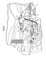
- An exhaust pipe 77 is connected to a lower surface of the cylinder head, and as shown in FIG. 2, the exhaust pipe 77 is connected to an exhaust muffler 78 placed on the right side of the swing arm 48.
- the swing arm 48 has, in substantially the center thereof, an opening 81 formed so that a vertical width becomes smaller toward the rear, and is formed into a substantially triangular shape with a narrowing rear end when laterally viewed.
- the front of the swing arm 48 are fastened, at two upper and lower spots, to the crank case 44 of the engine E with bolts 79 and 79.
- An axle 80 of the rear wheel WR is supported at the rear of the swing arm 48.
- the lower end of the rear cushion 64 is connected to the rear end of the swing arm 48 backward of the axle 80.
- a rear wheel disk brake 83 mounted to the rear wheel WR includes: a brake disk 84 rotating with the rear wheel WR; a pair of pads 85 and 85 placed to face opposite surfaces of the brake disk 84; and a caliper device 86 that supports the pads 85 and 85 and exerts a force to press the pads 85 and 85 against the brake disk 84.
- the caliper device 86 is supported on the swing arm 48 that supports the axle 80 of the rear wheel WR.
- the caliper device 86 includes: a caliper body 87 part of which is placed in the opening 81 of the swing arm 48; and a bracket 88 that supports the caliper body 87 slidably in a direction parallel to a rotational axis of the brake disk 84 and supports the pads 85 and 85 slidably in the direction parallel to the rotational axis of the brake disk 84, and that is secured to the swing arm 48.
- the bracket 88 integrally includes: a pair of support portions 88a and 88a spaced peripherally of the brake disk 84, and formed into a substantially U-shape so as to span an outer periphery of the brake disk 84; and a connecting portion 88b connecting the support portions 88a and 88a.
- Back plates 89 and 89 of the pads 85 and 85 include shoulders 89a, 89a at opposite ends thereof along a periphery of the brake disk 84.
- the shoulders 89a and 89a are slidably fitted into guide grooves 90 and 90 provided in the support portions 88a and 88a of the bracket 88 via retainers 91 and 91.
- the connecting portion 88b is disposed between the brake disk 84 and the swing arm 48, and mounted to the swing arm 48 with a pair of bolts 92 and 92 backward of the opening 81.
- the caliper body 87 is constituted by an acting portion 87a and a reacting portion 87b placed on opposite sides of the brake disk 84, and a spanning portion 87c that spans the brake disk 84 and connects the acting portion 87a and the reacting portion 87b.
- the acting portion 87a is placed at the rear in the opening 81.
- the acting portion 87a of the caliper body 87 is connected to the support portions 88a and 88a of the bracket 88 via a pair of slide pins 93 and 94 parallel to the rotational axis of the brake disk 84.
- the caliper body 87 is supported on the bracket 88 slidably in a direction parallel to the rotational axis of the brake disk 84.
- a cylinder hole 95 opening on the side of the brake disk 84 is provided in the acting portion 87a.
- a brake piston 96 that can press one of the back plates 89 of the pads 85 against the brake disk 84 is slidably fitted into the cylinder hole 95.
- a press surface 97 that can evenly press the other of the back plates 89 of the pads 85 is formed on the reacting portion 87b.
- a recess 98 that allows an entire thickness of the pad 85 to be always visually identified from outside is provided in a portion covering from outside the pad 85 that is placed between the acting portion 87a of the caliper body 87 and the brake disk 84 in the bracket 88 constituting the caliper device 86. Further, the recess 98 is provided in a side surface facing the brake disk 84 of the connecting portion 88b of the bracket 88 so that the pad 85 can be visually identified together with part of the back plate 89.
- the lower end of the rear cushion 64 provided between the swing arm 48 and the body frame F is connected to the swing arm 48 backward of the caliper device 86 in the rear wheel disk brake 83.
- the recess 98 is provided in the connecting portion 88b of the bracket 88 at a position where the caliper device 86 can be visually identified between the rear wheel WR and the rear cushion 64 when viewed diagonally from above the rear of the rear wheel as shown in FIG. 4.
- the recess 98 is formed so that the pad 85 can be visually identified within a range of an angle ⁇ of, for example, about 20 degrees upward and downward.
- a drum brake 103 for a parking brake is fitted to a hub 102 of the rear wheel WR, a lever 104 for actuating the drum brake 103 to operate is placed outside the swing arm 48, and a rotational axis 105 to which a base end of the lever 104 is secured rotatably passes through the swing arm 48 to protrude into the drum brake 103.
- an end of an outer cable 107 included in a brake cable 106 is supported on a lower portion of the swing arm 48, and an end of an inner cable 108 protruding from the end of the outer cable 107 is connected to a tip of the lever 104.
- Three support bosses 48a, 48b, and 48c are integrally provided on the swing arm 48 so as to protrude laterally outward.
- the exhaust muffler 78 fastened to the support bosses 48a to 48c with bolts 109 is placed laterally outside the swing arm 48 so as to laterally cover the caliper body 87 placed in the opening 81.
- the caliper body 87 is placed between the support bosses 48a and 48b among the support bosses 48a to 48c, and the support bosses 48a and 48b can protect the caliper body 87.
- the rear wheel disk brake 83 fitted to the rear wheel WR includes the caliper device 86 that supports the pads 85 and 85 that can be pressed against the brake disk 84 rotating with the rear wheel WR and exerts a force to press the pads 85 and 85 against the brake disk 84.
- the caliper device 86 is supported on the swing arm 48 that supports the axle 80 of the rear wheel WR.
- the recess 98 that allows the entire thickness of the pad 85 to be always visually identified from outside is provided in the portion of the bracket 88 that constitutes the caliper device 86, the portion covering one of the pads 85 and 85 from outside.
- the entire thickness of the pad 85 can be always visually identified via the recess 98, thereby increasing a degree of freedom in positioning of the caliper device 86 and checking a remaining amount of the pad 85 in the rear wheel disk brake 83.
- the swing arm 48 has the opening 81 in substantially the center thereof; is formed into the substantially triangular shape when laterally viewed; is placed on the right of the rear wheel WR so as to support the axle 80 of the rear wheel WR at the rear end thereof; and includes the caliper body 87 to which the brake piston 96 is slidably fitted and part of which is placed in the opening 81, and the bracket 88 formed by connecting the pair of support portions 88a and 88a that are spaced peripherally of the brake disk 84 and that support the pair of pads 85 and 85 via the connecting portion 88b placed between the brake disk 84 and the swing arm 48.
- the recess 98 is provided in the side surface facing the brake disk 84 of the connecting portion 88b.
- the rear wheel disk brake 83 is configured as described above to prevent the caliper device 86 from protruding from a vehicle body.
- the recess 98 is provided in the connecting portion 88b placed between the swing arm 48 and the brake disk 84 in the bracket 88 that constitutes part of the caliper device 86, thereby eliminating the need for specific machining of the swing arm 48, allowing the remaining amount of the pad 85 to be checked using a small space, and reducing the cost and weight of the swing arm 48.
- the recess 98 is provided in the connecting portion 88b of the bracket 88 in the position where the caliper device 86 is visually identified between the rear wheel WR and the rear cushion 64 when viewed diagonally from above the rear of the rear wheel WR, thereby allowing the remaining amount of the pad 85 to be confirmed diagonally from above the rear of the rear wheel WR with a sufficient space to facilitate the check.
- the invention is applicable to a motor cycle or a motor tricycle other than the scooter type vehicle.
- the invention can be implemented in connection with a front wheel disk brake.
- a caliper device which supports pads that can be pressed against a brake disk rotating with a wheel and which exerts a force to press the pads against the brake disk, is supported on a support member that supports an axle of the wheel.
- a recess that allows an entire thickness of the pad to be always visually identified from outside, is provided in a portion of a member that constitutes the caliper device, the portion covering the pad from outside.
Landscapes
- Engineering & Computer Science (AREA)
- General Engineering & Computer Science (AREA)
- Mechanical Engineering (AREA)
- Braking Arrangements (AREA)
- Axle Suspensions And Sidecars For Cycles (AREA)
Abstract
Description
Claims (3)
- A pad remaining amount checking structure in a disk brake of a vehicle in which a caliper device that supports pads that can be pressed against a brake disk rotating with a wheel and exerts a force to press the pads against the brake disk is supported on a support member that supports an axle of the wheel,
wherein a recess that allows an entire thickness of a pad to be always visually identified from outside is provided in a portion of a member that constitutes the caliper device, the portion covering the pad from outside. - The pad remaining amount checking structure in a disk brake of a vehicle according to claim 1, wherein a swing arm that is a support member has an opening in substantially the center thereof and is placed on one side of a rear wheel so as to support the axle of the rear wheel at a rear end thereof, wherein the caliper device includes a caliper body to which a brake piston is slidably fitted and part of which is placed in the opening, and a bracket formed by connecting a pair of support portions that are spaced peripherally of the brake disk and that support the pads via a connecting portion placed between the brake disk and the swing arm, and is supported on the swing arm, and wherein the recess is provided in a side surface facing the brake disk of the connecting portion.
- The pad remaining amount checking structure in a disk brake of a vehicle according to claim 2, wherein a lower end of a rear cushion provided between the swing arm swingably supported on an engine provided on a body frame and the body frame is connected to the swing arm backward of the caliper device, and wherein the recess is provided in the connecting portion of the bracket in a position where the caliper device is visually identified between the rear wheel and the rear cushion when viewed diagonally from above the rear of the rear wheel.
Applications Claiming Priority (2)
| Application Number | Priority Date | Filing Date | Title |
|---|---|---|---|
| JP2004050180A JP4430429B2 (en) | 2004-02-25 | 2004-02-25 | Vehicle with disc brake |
| JP2004050180 | 2004-02-25 |
Publications (2)
| Publication Number | Publication Date |
|---|---|
| EP1568910A1 true EP1568910A1 (en) | 2005-08-31 |
| EP1568910B1 EP1568910B1 (en) | 2008-03-12 |
Family
ID=34747478
Family Applications (1)
| Application Number | Title | Priority Date | Filing Date |
|---|---|---|---|
| EP05004033A Expired - Lifetime EP1568910B1 (en) | 2004-02-25 | 2005-02-24 | Pad remaining amount checking structure in disk brake of vehicle |
Country Status (4)
| Country | Link |
|---|---|
| US (1) | US7267204B2 (en) |
| EP (1) | EP1568910B1 (en) |
| JP (1) | JP4430429B2 (en) |
| DE (1) | DE602005005232T2 (en) |
Families Citing this family (5)
| Publication number | Priority date | Publication date | Assignee | Title |
|---|---|---|---|---|
| KR20050096585A (en) * | 2004-03-31 | 2005-10-06 | 현대자동차주식회사 | Throttle body fixing structure |
| JP4781650B2 (en) * | 2004-09-17 | 2011-09-28 | 川崎重工業株式会社 | Vehicle shift lever device |
| ITMI20071280A1 (en) * | 2007-06-26 | 2008-12-27 | Piaggio & C Spa | MOTORCYCLE PROVIDED WITH A PLURALITY OF BRAKE CALIPERS AGENTS ON ITS REAR WHEEL |
| US7877216B2 (en) * | 2008-07-30 | 2011-01-25 | Honeywell International Inc. | Method, system, and apparatus for friction pad wear and brake condition monitoring |
| JP5835684B2 (en) * | 2011-03-22 | 2015-12-24 | 本田技研工業株式会社 | Evaporative fuel treatment equipment for motorcycles |
Citations (4)
| Publication number | Priority date | Publication date | Assignee | Title |
|---|---|---|---|---|
| JPS5261676A (en) * | 1975-11-15 | 1977-05-21 | Tokico Ltd | Disc brake |
| US4162721A (en) * | 1976-07-28 | 1979-07-31 | Sumitomo Electric Industries, Ltd. | Sliding caliper type disc brake |
| JPS5857531A (en) * | 1981-09-30 | 1983-04-05 | Nissin Kogyo Kk | Device for preventing excessive wear of lining |
| JP2001097269A (en) * | 1999-09-30 | 2001-04-10 | Honda Motor Co Ltd | Motorcycle |
Family Cites Families (3)
| Publication number | Priority date | Publication date | Assignee | Title |
|---|---|---|---|---|
| JPS5423875A (en) * | 1977-07-25 | 1979-02-22 | Sumitomo Electric Ind Ltd | Pad wear alarm device of disc brake |
| JP2544937Y2 (en) * | 1991-05-22 | 1997-08-20 | 曙ブレーキ工業株式会社 | Disc brake wear indicator |
| US5819886A (en) * | 1996-07-03 | 1998-10-13 | Null; Robert L. | Trailer brake system with dual piston calipers |
-
2004
- 2004-02-25 JP JP2004050180A patent/JP4430429B2/en not_active Expired - Lifetime
-
2005
- 2005-02-24 US US11/063,732 patent/US7267204B2/en not_active Expired - Lifetime
- 2005-02-24 DE DE602005005232T patent/DE602005005232T2/en not_active Expired - Lifetime
- 2005-02-24 EP EP05004033A patent/EP1568910B1/en not_active Expired - Lifetime
Patent Citations (4)
| Publication number | Priority date | Publication date | Assignee | Title |
|---|---|---|---|---|
| JPS5261676A (en) * | 1975-11-15 | 1977-05-21 | Tokico Ltd | Disc brake |
| US4162721A (en) * | 1976-07-28 | 1979-07-31 | Sumitomo Electric Industries, Ltd. | Sliding caliper type disc brake |
| JPS5857531A (en) * | 1981-09-30 | 1983-04-05 | Nissin Kogyo Kk | Device for preventing excessive wear of lining |
| JP2001097269A (en) * | 1999-09-30 | 2001-04-10 | Honda Motor Co Ltd | Motorcycle |
Non-Patent Citations (3)
| Title |
|---|
| PATENT ABSTRACTS OF JAPAN vol. 001, no. 125 (M - 042) 19 October 1977 (1977-10-19) * |
| PATENT ABSTRACTS OF JAPAN vol. 007, no. 145 (M - 224) 24 June 1983 (1983-06-24) * |
| PATENT ABSTRACTS OF JAPAN vol. 2000, no. 21 3 August 2001 (2001-08-03) * |
Also Published As
| Publication number | Publication date |
|---|---|
| DE602005005232D1 (en) | 2008-04-24 |
| EP1568910B1 (en) | 2008-03-12 |
| US20050217947A1 (en) | 2005-10-06 |
| US7267204B2 (en) | 2007-09-11 |
| JP4430429B2 (en) | 2010-03-10 |
| DE602005005232T2 (en) | 2009-03-19 |
| JP2005240885A (en) | 2005-09-08 |
Similar Documents
| Publication | Publication Date | Title |
|---|---|---|
| EP1820710B1 (en) | Two-wheeled vehicle with brake apparatus | |
| JP5261827B2 (en) | Canister mounting structure for saddle-ride type vehicles | |
| EP3093226A1 (en) | Two-wheeled automobile | |
| JP4563904B2 (en) | Motorcycle | |
| CN102039963A (en) | Pedal periphery structure of straddle-type vehicle | |
| JP2013071596A (en) | Saddle type vehicle | |
| JP4247860B2 (en) | Motorcycle | |
| JP5973211B2 (en) | Saddle riding vehicle | |
| EP1568910B1 (en) | Pad remaining amount checking structure in disk brake of vehicle | |
| JP4825543B2 (en) | Brake support structure | |
| CN109720328B (en) | straddle vehicle | |
| WO2015029520A1 (en) | Automatic two-wheeled vehicle | |
| US20050082821A1 (en) | Brake hose support structure | |
| TWI731637B (en) | Saddle-type vehicle | |
| JP2009102005A (en) | Motorcycle | |
| JP7305817B1 (en) | saddle-riding vehicle | |
| US11654999B2 (en) | Rear wheel braking device for motorcycle | |
| JP7579216B2 (en) | Saddle-type vehicle equipped with auxiliary brakes | |
| WO2021214791A1 (en) | Two-wheeled of three-wheeled vehicle comprising an accelerator position sensor | |
| JP7561110B2 (en) | Saddle-type vehicle | |
| CN100532188C (en) | Support structure of power unit of two-wheeled motorcycle | |
| JP6839301B2 (en) | Brake piping structure for saddle-mounted vehicles | |
| JP7663615B2 (en) | Saddle-type vehicle | |
| JP7573583B2 (en) | ABS modulator piping arrangement structure | |
| CN221498321U (en) | Straddle-type vehicle |
Legal Events
| Date | Code | Title | Description |
|---|---|---|---|
| PUAI | Public reference made under article 153(3) epc to a published international application that has entered the european phase |
Free format text: ORIGINAL CODE: 0009012 |
|
| AK | Designated contracting states |
Kind code of ref document: A1 Designated state(s): AT BE BG CH CY CZ DE DK EE ES FI FR GB GR HU IE IS IT LI LT LU MC NL PL PT RO SE SI SK TR |
|
| AX | Request for extension of the european patent |
Extension state: AL BA HR LV MK YU |
|
| 17P | Request for examination filed |
Effective date: 20051025 |
|
| AKX | Designation fees paid |
Designated state(s): DE IT |
|
| GRAP | Despatch of communication of intention to grant a patent |
Free format text: ORIGINAL CODE: EPIDOSNIGR1 |
|
| GRAS | Grant fee paid |
Free format text: ORIGINAL CODE: EPIDOSNIGR3 |
|
| GRAA | (expected) grant |
Free format text: ORIGINAL CODE: 0009210 |
|
| AK | Designated contracting states |
Kind code of ref document: B1 Designated state(s): DE IT |
|
| REF | Corresponds to: |
Ref document number: 602005005232 Country of ref document: DE Date of ref document: 20080424 Kind code of ref document: P |
|
| PLBE | No opposition filed within time limit |
Free format text: ORIGINAL CODE: 0009261 |
|
| STAA | Information on the status of an ep patent application or granted ep patent |
Free format text: STATUS: NO OPPOSITION FILED WITHIN TIME LIMIT |
|
| 26N | No opposition filed |
Effective date: 20081215 |
|
| REG | Reference to a national code |
Ref country code: DE Ref legal event code: R081 Ref document number: 602005005232 Country of ref document: DE Owner name: HITACHI ASTEMO, LTD., HITACHINAKA-SHI, JP Free format text: FORMER OWNERS: NISSIN KOGYO CO., LTD., UEDA, NAGANO, JP; HONDA MOTOR CO., LTD., TOKYO, JP Ref country code: DE Ref legal event code: R082 Ref document number: 602005005232 Country of ref document: DE Representative=s name: WEICKMANN & WEICKMANN PATENT- UND RECHTSANWAEL, DE Ref country code: DE Ref legal event code: R081 Ref document number: 602005005232 Country of ref document: DE Owner name: NISSIN KOGYO CO., LTD., TOMI-CITY, JP Free format text: FORMER OWNERS: NISSIN KOGYO CO., LTD., UEDA, NAGANO, JP; HONDA MOTOR CO., LTD., TOKYO, JP |
|
| REG | Reference to a national code |
Ref country code: DE Ref legal event code: R081 Ref document number: 602005005232 Country of ref document: DE Owner name: HITACHI ASTEMO, LTD., HITACHINAKA-SHI, JP Free format text: FORMER OWNER: NISSIN KOGYO CO., LTD., TOMI-CITY, NAGANO, JP |
|
| PGFP | Annual fee paid to national office [announced via postgrant information from national office to epo] |
Ref country code: IT Payment date: 20230110 Year of fee payment: 19 Ref country code: DE Payment date: 20221229 Year of fee payment: 19 |
|
| REG | Reference to a national code |
Ref country code: DE Ref legal event code: R119 Ref document number: 602005005232 Country of ref document: DE |
|
| PG25 | Lapsed in a contracting state [announced via postgrant information from national office to epo] |
Ref country code: DE Free format text: LAPSE BECAUSE OF NON-PAYMENT OF DUE FEES Effective date: 20240903 |
|
| PG25 | Lapsed in a contracting state [announced via postgrant information from national office to epo] |
Ref country code: DE Free format text: LAPSE BECAUSE OF NON-PAYMENT OF DUE FEES Effective date: 20240903 |
|
| PG25 | Lapsed in a contracting state [announced via postgrant information from national office to epo] |
Ref country code: IT Free format text: LAPSE BECAUSE OF NON-PAYMENT OF DUE FEES Effective date: 20240224 |