EP1568893B1 - Linear actuator - Google Patents
Linear actuator Download PDFInfo
- Publication number
- EP1568893B1 EP1568893B1 EP05003939A EP05003939A EP1568893B1 EP 1568893 B1 EP1568893 B1 EP 1568893B1 EP 05003939 A EP05003939 A EP 05003939A EP 05003939 A EP05003939 A EP 05003939A EP 1568893 B1 EP1568893 B1 EP 1568893B1
- Authority
- EP
- European Patent Office
- Prior art keywords
- piston
- rod
- cylinder
- leg
- linear actuator
- Prior art date
- Legal status (The legal status is an assumption and is not a legal conclusion. Google has not performed a legal analysis and makes no representation as to the accuracy of the status listed.)
- Expired - Lifetime
Links
- 230000008878 coupling Effects 0.000 claims description 3
- 238000010168 coupling process Methods 0.000 claims description 3
- 238000005859 coupling reaction Methods 0.000 claims description 3
- 230000009471 action Effects 0.000 description 4
- 230000007704 transition Effects 0.000 description 4
- 230000007246 mechanism Effects 0.000 description 3
- 230000000694 effects Effects 0.000 description 2
- 239000012530 fluid Substances 0.000 description 2
- 238000000034 method Methods 0.000 description 2
- 238000012986 modification Methods 0.000 description 2
- 230000004048 modification Effects 0.000 description 2
- 230000008569 process Effects 0.000 description 2
- 238000007789 sealing Methods 0.000 description 2
- 230000008859 change Effects 0.000 description 1
- 230000006835 compression Effects 0.000 description 1
- 238000007906 compression Methods 0.000 description 1
Images



Classifications
-
- B—PERFORMING OPERATIONS; TRANSPORTING
- B64—AIRCRAFT; AVIATION; COSMONAUTICS
- B64C—AEROPLANES; HELICOPTERS
- B64C25/00—Alighting gear
- B64C25/02—Undercarriages
- B64C25/08—Undercarriages non-fixed, e.g. jettisonable
- B64C25/10—Undercarriages non-fixed, e.g. jettisonable retractable, foldable, or the like
- B64C25/18—Operating mechanisms
- B64C25/22—Operating mechanisms fluid
-
- B—PERFORMING OPERATIONS; TRANSPORTING
- B64—AIRCRAFT; AVIATION; COSMONAUTICS
- B64C—AEROPLANES; HELICOPTERS
- B64C25/00—Alighting gear
- B64C25/02—Undercarriages
- B64C25/08—Undercarriages non-fixed, e.g. jettisonable
- B64C25/10—Undercarriages non-fixed, e.g. jettisonable retractable, foldable, or the like
- B64C25/16—Fairings movable in conjunction with undercarriage elements
-
- F—MECHANICAL ENGINEERING; LIGHTING; HEATING; WEAPONS; BLASTING
- F15—FLUID-PRESSURE ACTUATORS; HYDRAULICS OR PNEUMATICS IN GENERAL
- F15B—SYSTEMS ACTING BY MEANS OF FLUIDS IN GENERAL; FLUID-PRESSURE ACTUATORS, e.g. SERVOMOTORS; DETAILS OF FLUID-PRESSURE SYSTEMS, NOT OTHERWISE PROVIDED FOR
- F15B15/00—Fluid-actuated devices for displacing a member from one position to another; Gearing associated therewith
- F15B15/20—Other details, e.g. assembly with regulating devices
- F15B15/26—Locking mechanisms
- F15B15/261—Locking mechanisms using positive interengagement, e.g. balls and grooves, for locking in the end positions
Definitions
- the present invention relates to a leg structure for a flying or floating moving body including a support structure for a flying or floating moving body, having a linear actuator provided with a mechanical locking means and mechanically and manually operated releasing means for the lock.
- US 5,097,748 describes a linear actuator having a piston which can be mechanically locked in a specific position. Besides the possibility of releasing the locking position by means of a hydraulic fluid, mechanical locking means are provided for manually releasing the locking position.
- the mechanical release means in the embodiment of Figs 3 and 4, include a pin for pressing the piston out of the locking position.
- the locking position is defined by a plurality of balls received in a cage and adapted to move radially into and out of a locking groove. The manner of use of this actuator is not described.
- US 5,184,465 describes a landing gear track strut/actuator used for moving an aircraft landing gear into and out of a stowing position.
- the actuator includes mechanical locking means which can be mechanically and manually released.
- the locking means include a snap ring attached to a tube and adapted to be received in a recess.
- a manually actuated swing lever is pivotably fixed to the tube for manually shifting the snap ring out from the recess for mechanically releasing the locking condition.
- US 3,813,065 describes a locking mechanism for coaxial load carrying members which utilises a one piece, chamfered locking ring as a locking member between the load carrying members.
- the load carrying mechanism is used for a holdback bar assembly of the type which is utilised to hold an aircraft until a sufficient force is reached by steam catapult to release an aeroplane.
- the mechanism includes a plurality of holdback bars and a pulling bar acting on a landing gear.
- a leg structure which for the time of stowing provides support from below when the leg for a flying or floating moving body is stowed.
- the leg structure includes a leg support structure which for the time of stowing provides support of the leg from below when the leg for a flying or floating moving body is stowed.
- the structure includes a linear actuator which allows even in a case where the oil pressure supply of the moving body fails, when the rear part of the push rod is pressed, to release locking of the piston and to advance the piston and piston rod due to the weight of the leg, so that support of the leg is released.
- the piston is mechanically locked at the time when the piston is in a prescribed position of a stroke.
- the lock is released by introducing pressurized oil supplied to the translation cylinder so that the piston is released.
- the present invention makes use of a linear actuator of a simple structure that is capable of locking a piston and is capable of releasing locking with a simple operation in the event that the pressurized oil source becomes damaged.
- a linear actuator capable of generating thrust in a direction back and forth which comprises:
- an overall cylindrical space of the cylinder has an inner wall of a prescribed internal diameter D, and a groove to the rear of the inner wall having an internal dimension larger than the internal diameter D is provided.
- a piston seals a gap with the inner wall and is supported so as to be capable of freely sliding back and forth.
- the rear end of the cam rod is exposed at the rear of the piston and supported at the piston in such a manner as to be freely slidable in a direction back and forth.
- the cam rod has a profile changing at one location from a small diameter part of diameter D1 to a large diameter part of a diameter D2 larger than D1 in accordance with a transition from the rear to the front.
- a locking ram constituting a block supported at the piston in a manner freely slidable in a radial direction.
- An outer end of the locking ram is capable of being projected out from or pulled in to a line for a distance of D/2 from the center of the piston, so that an inner end of the locking ram is capable of coming into contact with the profile.
- a spring built-into the piston urges the cam rod to the rear.
- a push rod constitutes an axial body supported in a freely sliding manner in a direction back and forth at the cylinder so that the rear end is exposed at the rear part of the cylinder and the front end is exposed at the rear part of the overall cylindrical space.
- a linear actuator is further comprised of a piston rod constituting a cylindrical member, with one end coupled to the front part of the piston, and the other end passing through so as to seal the front part of the cylinder so as to enable coupling at a rod end.
- Pressurized oil is selectively provided to a front hydraulic chamber and a rear hydraulic chamber of the overall cylindrical space dividing the piston to the front and rear, and the rod end is connected to a subject of action urged to the front by a prescribed force.
- a piston rod constituting a cylindrical member has one end coupled to the front part of the piston, with the other end passing through so as to seal the front part of the cylinder so as to enable coupling at a rod end.
- Pressurized oil is selectively provided to a front hydraulic chamber and a rear hydraulic chamber of the overall cylindrical space dividing the piston to the front and rear, and the rod end is connected to a subject of action urged to the front by a prescribed force.
- the piston rod is therefore capable of moving back and forth, and in the event that the pressurized oil supply fails when the piston moves to the rear so as to become locked, when the rear part of the push rod is pushed, locking of the piston is released, and the piston can be made to advance using a prescribed force.
- the subject of action is a leg support structure for the time of stowing providing support from below when the leg for a flying or floating moving body is stowed.
- the subject of action is a leg support structure for the time of stowing providing support from below when the leg for a flying or floating moving body is stowed. Therefore, even in cases where the oil pressure supply of the moving body fails, when the rear part of the push rod is pressed, locking of the piston is released, the piston and piston rod advance due to the weight of the leg, and supporting of the leg is released.
- the linear actuator further comprises a release lever constituting a lever capable of pushing the rear end of the push rod to the front, and the release lever is supported in a freely swinging manner at an outer part of the cylinder.
- the release lever is supported in a freely swinging manner at an outer part of the cylinder. Therefore, when the release lever is made to swing as a result of an external operation, the release lever pushes the rear part of the push rod to the front, and the push rod can make the cam rod move to the front.
- the linear actuator is such that the cylinder has a swinging support point supporting the linear actuator in a manner capable of swinging at an outer wall.
- the cylinder has a swinging support point supporting the linear actuator in a manner capable of swinging at an outer wall.
- the translation cylinder is therefore capable of swinging centrally about the swinging support point.
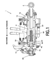
- FIG. 1 is a cross-sectional view of a linear actuator of an embodiments provided for the present invention.
- FIG. 2 is a partial cross-sectional view of a linear actuator.
- a linear actuator 1 is an item of equipment capable of generating thrust in a direction back and forth, and is comprised of a cylinder 10, piston 20, piston rod 30, cam rod 40, locking rams 50, spring 60, push-rod 70, and release lever 80.
- a hydraulic valve (not shown) supplies pressurized oil to the linear actuator 1.
- the cylinder 10 has an overall cylindrical space H, and is comprised of a cylinder tube 11, front head cover 12, and rear head cover 13.
- the overall cylindrical space H has an inner wall S of a prescribed internal diameter D and is provided with a groove G to the rear of the inner wall S and having an internal dimension larger than the internal diameter D.
- the cylinder tube 11 is a cylindrical member of internal diameter D.
- the inner wall S is formed on the inside of the cylinder tube 11.
- a swinging support point 10a (shown in FIG. 4) capable of enabling the translation cylinder to swing is provided on an outer wall of the cylinder tube 11.
- the front head cover 12 is a member provided at the front of the cylinder tube 11.
- the end surface of the front head cover 12 closes the front of the overall cylindrical space H.
- FIG. 1 shows the cylinder tube 11 fitting into a hole provided at the front head cover 12.
- the rear head cover 13 is a member provided at the rear of the cylinder tube 11.
- the end surface of the rear head cover 13 closes the rear of the overall cylindrical space H.
- FIG. 1 is a view showing a cylinder tube 11 inserted into a hole provided at the rear head cover 13, with an inner wall S1 of the hole for the rear head cover 13 and the end surface of the rear of the cylinder tube 11 combining so as to form a groove G.
- the piston 20 is a member supported in a manner so as to be slidable in a direction back and forth while making a gap at the inner wall S fluid-tight, and is constructed of a piston body 21 and a piston seal 22.
- the piston body 21 is a substantially columnar member having an external diameter that is slightly smaller than the internal diameter of the inner wall S.
- a seal groove is provided in a ring-shape about the outer surface of the piston body 21.
- the piston seal 22 is a member for sealing a gap between inner wall S and the piston body 21 in a fluid-tight manner.
- the piston seal 22 is housed in the seal groove.
- the piston 20 slides at the piston seal 22 and the inner wall S so as to move in a direction back and forth.
- the piston 20 divides the overall cylindrical space H from front to rear.
- the front part of the overall cylindrical space H is referred to as front hydraulic chamber H1 and the rear part of the overall cylindrical space H is referred to as rear hydraulic chamber H2.
- the cam rod 40 is an axial body with a rear end exposed at the rear of the piston supported at the piston in such a manner as to be freely slidable in a direction from front to rear.
- the axial body has a profile P changing from a small diameter section of diameter D1 to a large diameter section of diameter D2 larger than D1 in accompaniment with a transition from the rear to the front at one location.
- FIG. 2 shows a portion of the cam rod 40 where a portion (small diameter part) of diameter D1 on the side of the rear end, a portion formed in a conical shape broadening from a diameter D1 to a diameter D2 and a portion (large diameter part) of diameter D2 are formed into a single body.
- the outer surfaces of the small diameter part, conical part, and large diameter part form a profile P.
- a side of the front of the cam rod 40 is hollowed out into a columnar shape into which a portion to the rear of the spring 60 described later is inserted.
- the locking ram 50 is a block supported at the piston 20 so as to be freely slidable in a radial direction.
- This block is such that an end (hereafter referred to as the "outer end of the locking ram") on the outer side of the radial direction may be projected out or pulled in from a line for a distance D/2 from the center of the piston in such a manner that the end (hereafter referred to as the “inner end of the locking ram") of the inside of the radial direction comes into contact with the profile P.
- the outer end of the locking ram is withdrawn from the outer surface of the piston 20. Further, when the inner end of the locking ram makes contact with the large diameter part of the profile P, the outer end of the locking ram projects out from the outer surface of the piston 20.
- FIG. 2 shows when the piston 20 is positioned to the rear of the overall cylindrical space H, the inner end of the locking ram comes into contact with the large diameter part, and the outer end of the locking ram fits into the groove G.
- the spring 60 is a mechanical element built-into the piston urging the cam rod to the rear.
- FIG. 1 and FIG. 2 show the coiled spring built-into the piston 20.
- a front end of the coiled spring 60 comes into contact with a hole formed in the integral piston 20 and piston rod 30.
- the rear end of the coiled spring 60 comes into contact with a hole formed in the cam rod 40.
- the spring 60 urges the cam rod 40 to the rear with a force equal to the compression force.
- the push-rod 70 is an axial body supported at the cylinder in a freely sliding manner in a direction from front to rear. A rear end of this axial body is exposed at a rear part of the cylinder 10 and a front end is exposed at a rear part of the overall cylindrical space H. While the piston 20 is moving at the rear part of the overall cylindrical space H, in this state, the front end of the push-rod 70 is capable of pushing the cam rod 40.
- FIG. 2 shows when the front end of the push-rod 70 comes into contact with the rear end of the cam rod 40.
- the cam rod 40 moves to the front against the urging force of the spring 50.
- the cam rod 40 moves to the front within the piston 20
- the inner end of the locking ram 50 comes into contact with the small diameter part of the profile P and the outer end of the locking ram 50 is withdrawn from the outer surface of the piston 20.
- the release lever 80 is a lever for advancing the push rod 70 forward due to an operation from outside.
- a front end of the release lever 80 is coupled in a freely sliding manner to the rear end of the push rod 70.
- the rear end of the release lever 80 is connected to an operation wire.
- the operation wire can then be pulled by an operator.
- a swinging shaft provided at a central part of the release lever 80 is connected in a freely rocking manner to the rear head cover 13.
- the distance between the front end and the swinging shaft is shorter than the distance between the rear end and the swinging shaft.
- the hydraulic valve is hydraulic equipment for selectively supplying compressed oil to the front hydraulic chamber H1 and the rear hydraulic chamber H2 of the overall cylindrical space H.
- the front hydraulic chamber H1 and the rear hydraulic chamber H2 can be made to communicate with the power line and the tank line of the pressurized oil source.
- FIG. 4A and FIG. 4B are operation views of a linear actuator of the embodiment of the present invention.
- FIG. 4A shows a situation where the locking ram fits into the groove G.
- FIG. 4B shows a situation where the release lever is pulled so as to release fitting of the locking ram and the groove G.
- FIG. 4A and FIG. 4B the front of the linear actuator faces downwards and the rear of the linear actuator faces upwards.
- the hydraulic valve is operated, the rear hydraulic chamber H2 communicates with the power line, and the front hydraulic chamber H1 communicates with the tank line.
- Pressurized oil then flows into the rear hydraulic chamber H2.
- the cam rod 40 then moves to the front against the urging of the spring 60 because the pressurized oil presses the rear end of the cam rod 40.
- Locations of the profile P making contact with the inner end of the locking ram then move from the large diameter part to the small diameter part and the locking ram 50 moves towards the inside in a radial direction. Fitting of the locking ram 50 and the groove G then slips out.
- the pressurized oil then presses the piston 20 to the front.
- the piston 20 and the piston rod 30 then advance.
- the hydraulic valve is operated, the front hydraulic chamber H1 communicates with the power line, and the rear hydraulic chamber H2 communicates with the tank line.
- the pressurized oil pushes the piston 20 to the rear and the piston 20 and piston rod 30 therefore retract.
- the pressurized oil therefore presses the front end of the cam rod 40.
- the conical part of the profile P then presses the inner end of the locking ram to the rear.
- the locking ram 50 is then subjected to a force to the outside in a radial direction as the result of a wedging effect.
- the piston 20 then moves to the rear part of the overall cylindrical space H so that when the outer end of the locking ram reaches a position facing the groove G, the locking ram 50 moves to the outer side in a radial direction, and the outer end of the locking ram fits with the groove G.
- the piston 20 and the piston rod 30 then move to the rear so as to reach the state of FIG. 1.
- the piston 20 and piston rod 30 advance.
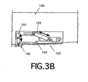
- FIG. 3A and FIG. 3B are outline drawings of a leg structure for moving body use of the embodiment of the present invention.
- the posture of the leg structure for moving body use changes between a stowed posture for stowing a wheel in a main structure 100 of the moving body and a landing posture for landing the wheel on a ground surface.
- FIG. 3A shows the landing posture
- FIG. 3B shows the stowed posture
- the leg structure for moving body use is comprised of an inboard hydraulic cylinder 101 (corresponding to the linear actuator) for inboard door use, an inboard door 102 (corresponding to a leg support structure for the time of storage), a leg supporting hydraulic cylinder 103, a leg 104, and an outboard door 105.
- the linear actuator 1 is adopted in the inboard hydraulic cylinder 101.
- One end of an operation wire (not shown) is connected to a release lever for the inboard hydraulic cylinder 101 for inboard door use and the other end is provided in a flight deck.
- the inboard hydraulic cylinder 101 is an actuator for opening and closing an inboard door 102 and is an actuator for supporting the leg 104 via an inboard door 102 in the stowed posture.
- the inboard hydraulic cylinder 101 is fixed in such a manner as to be capable of freely swinging at an inner wall of the stowing space for the leg about a swinging support point 10a provided at a central part of the linear actuator cylinder.
- the inboard door 102 is a door on the inside of the leg stowing space.
- the inboard door 102 is supported centered about one side in a freely swingable manner at the main structure 100.
- the inboard door 102 supports the weight of the leg 104 from below when closed.
- the leg supporting hydraulic cylinder 103 is a hydraulic cylinder for swinging the leg 104 between the landing posture and the stowed posture.
- the leg 104 is a support structure for a wheel landing on the ground when the moving body lands and a wheel support structure.
- the outboard door 105 is a door on the outside of the leg stowing space.
- leg supporting hydraulic cylinder 103 When the leg supporting hydraulic cylinder 103 extends the piston rod, the leg 104 adopts the landing posture and the outboard door 105 is opened. When the leg supporting hydraulic cylinder 103 retracts the piston rod, the leg 104 adopts the stowed posture and the outboard door 105 is closed.
- the inboard hydraulic cylinder 101 fixes movement of the inboard door 102 and the inboard door 102 supports the leg 104 from below.
- the inboard hydraulic cylinder 101 is then in a locked state.
- the piston and piston rod are therefore fixed, and the leg 104 maintains a stowed posture even if there is no pressurized oil from the pressurized oil source.
- the weight of the leg 104 then acts on the inboard door 102 and a rod end coupled to the piston rod of the inboard hydraulic cylinder 101 is urged towards the front.
- the inboard hydraulic cylinder 101 and the leg supporting hydraulic cylinder 103 are switched over at the appropriate time so that the posture of the leg structure of the moving body may be made to change between a landing posture and a stowed posture.
- the pilot of an airplane may pull the operation wire in the flight deck.
- the release lever 80 is then made to swing using the operation wire so as to push the push rod 70 of the inboard hydraulic cylinder 101.
- the locked state of the inboard hydraulic cylinder 101 is then released by the above operation.
- the weight of the leg 104 then pulls the rod end of the inboard hydraulic cylinder 101 in an advancing direction and the piston rod of the inboard hydraulic cylinder 101 extends.
- the leg 104 then loses the support of the inboard door 102, falls downwards, and adopts the landing posture.
- the posture of the leg 104 can then reliably adopt the landing posture.
- a groove G is provided to the rear of an inner wall S of the cylinder 10.
- a locking ram 50 capable of freely sliding in a radial direction and a cam rod 40 having a profile P changing with a transition from the rear to the front from a small diameter part to a large diameter part are provided at a piston 20.
- the inner end of the locking ram 50 makes contact with the profile P, the cam rod 40 is urged to the rear by the spring 60, and the cam rod 40 can be pushed to the front by a push rod 70.
- a hydraulic valve is provided for causing the piston 20 to move in a reciprocating manner.
- a piston rod 30 coupled to the piston 20 is provided and a rod end coupled to the piston rod 30 is coupled to an item that is acted upon urged by a prescribed force to the front. It is therefore possible to move the piston rod 30 to the front and back by switching the hydraulic valve.
- the piston 20 can be made to advance using a prescribed urging force.
Landscapes
- Engineering & Computer Science (AREA)
- Mechanical Engineering (AREA)
- Aviation & Aerospace Engineering (AREA)
- Physics & Mathematics (AREA)
- Fluid Mechanics (AREA)
- General Engineering & Computer Science (AREA)
- Actuator (AREA)
Description
- The present invention relates to a leg structure for a flying or floating moving body including a support structure for a flying or floating moving body, having a linear actuator provided with a mechanical locking means and mechanically and manually operated releasing means for the lock.
-
US 5,097,748 describes a linear actuator having a piston which can be mechanically locked in a specific position. Besides the possibility of releasing the locking position by means of a hydraulic fluid, mechanical locking means are provided for manually releasing the locking position. The mechanical release means, in the embodiment of Figs 3 and 4, include a pin for pressing the piston out of the locking position. The locking position is defined by a plurality of balls received in a cage and adapted to move radially into and out of a locking groove. The manner of use of this actuator is not described. -
US 5,184,465 describes a landing gear track strut/actuator used for moving an aircraft landing gear into and out of a stowing position. The actuator includes mechanical locking means which can be mechanically and manually released. The locking means include a snap ring attached to a tube and adapted to be received in a recess. A manually actuated swing lever is pivotably fixed to the tube for manually shifting the snap ring out from the recess for mechanically releasing the locking condition. -
US 3,813,065 describes a locking mechanism for coaxial load carrying members which utilises a one piece, chamfered locking ring as a locking member between the load carrying members. The load carrying mechanism is used for a holdback bar assembly of the type which is utilised to hold an aircraft until a sufficient force is reached by steam catapult to release an aeroplane. The mechanism includes a plurality of holdback bars and a pulling bar acting on a landing gear. - It is therefore a subject of the present invention to provide a safe leg structure which is easy to actuate in the event that the supply of hydraulic fluid fails.
- This need is fulfilled by the leg structure according to
claim 1. - According to the present invention a leg structure is provided which for the time of stowing provides support from below when the leg for a flying or floating moving body is stowed. The leg structure includes a leg support structure which for the time of stowing provides support of the leg from below when the leg for a flying or floating moving body is stowed. The structure includes a linear actuator which allows even in a case where the oil pressure supply of the moving body fails, when the rear part of the push rod is pressed, to release locking of the piston and to advance the piston and piston rod due to the weight of the leg, so that support of the leg is released.
- There is a desire to mechanically lock motion of a piston after operation as a result of oil pressure in the event of use as a linear actuator for a translation cylinder etc.
- In a typical structure, the piston is mechanically locked at the time when the piston is in a prescribed position of a stroke. When it is wished to release the lock, the lock is released by introducing pressurized oil supplied to the translation cylinder so that the piston is released.
- However, with the above structure, it is not possible for locking to be released in the event that a pressurized oil supply is damaged so that oil pressure cannot be supplied. There has therefore been a demand for a linear actuator for which locking can be reliably released even in the event of the pressurized oil supply becoming damaged.
- In order to resolve the aforementioned problems, the present invention makes use of a linear actuator of a simple structure that is capable of locking a piston and is capable of releasing locking with a simple operation in the event that the pressurized oil source becomes damaged.
- In the present invention, a linear actuator capable of generating thrust in a direction back and forth is used which comprises:
- a cylinder having an overall cylindrical space with an inner wall of a prescribed internal diameter D and being provided with a groove having an internal dimension larger than the internal diameter D to the rear of the inner wall, a piston, sealing a gap with the inner wall, supported so as to be capable of freely sliding back and forth, a cam rod, constituting an axial body supported at the piston so as to be capable of freely sliding back and forth with a rear end exposed at the rear of the piston, having a profile changing at one location from a small diameter part of diameter D1 to a large diameter part of a diameter D2 larger than D1 in accordance with a transition from the rear to the front, a locking ram constituting a block supported at the piston in a manner freely slidable in a radial direction, with an outer end of the locking ram constituting an end on the outside in a radial direction being capable of being projected out from or pulled in to a line for a distance of D/2 from the center of the piston so that an inner end of the locking ram constituting an end on the inside in the radial direction is capable of coming into contact with the profile, a spring built-into the piston urging the cam rod to the rear, a push rod, constituting an axial body supported in a freely sliding manner in a direction back and forth at the cylinder so that the rear end is exposed at the rear part of the cylinder and the front end is exposed at the rear part of the overall cylindrical space.
- While the piston moves to the rear part of the overall cylindrical space, the inner end of the locking ram presses against the large diameter part so that the outer end of the locking ram fits into the groove, and in this state, the front end of the push rod is able to press the cam rod.
- In the structure of the actuator described above, an overall cylindrical space of the cylinder has an inner wall of a prescribed internal diameter D, and a groove to the rear of the inner wall having an internal dimension larger than the internal diameter D is provided. A piston seals a gap with the inner wall and is supported so as to be capable of freely sliding back and forth. The rear end of the cam rod is exposed at the rear of the piston and supported at the piston in such a manner as to be freely slidable in a direction back and forth. The cam rod has a profile changing at one location from a small diameter part of diameter D1 to a large diameter part of a diameter D2 larger than D1 in accordance with a transition from the rear to the front. A locking ram constituting a block supported at the piston in a manner freely slidable in a radial direction is provided. An outer end of the locking ram is capable of being projected out from or pulled in to a line for a distance of D/2 from the center of the piston, so that an inner end of the locking ram is capable of coming into contact with the profile. A spring built-into the piston urges the cam rod to the rear. A push rod constitutes an axial body supported in a freely sliding manner in a direction back and forth at the cylinder so that the rear end is exposed at the rear part of the cylinder and the front end is exposed at the rear part of the overall cylindrical space. While the piston moves to the rear part of the overall cylindrical space, the inner end of the locking ram presses against the large diameter part so that the outer end of the locking ram fits into the groove, and in this state, the front end of the push rod is able to press the cam rod. When the piston then moves to the rear part of the overall cylindrical space so as to be locked, when the rear part of the push rod is then pushed, the push rod moves the cam rod to the front, the inner end of the locking ram collides with the small diameter part, the outer end of the locking ram comes out from the groove so that the piston is able to advance.
- In the following, a description is given of several embodiments of a linear actuator for the present invention. The present invention incorporates both any one of the embodiments disclosed below or two or more combinations thereof.
- A linear actuator is further comprised of a piston rod constituting a cylindrical member, with one end coupled to the front part of the piston, and the other end passing through so as to seal the front part of the cylinder so as to enable coupling at a rod end. Pressurized oil is selectively provided to a front hydraulic chamber and a rear hydraulic chamber of the overall cylindrical space dividing the piston to the front and rear, and the rod end is connected to a subject of action urged to the front by a prescribed force.
- In the configuration of the above embodiment, a piston rod constituting a cylindrical member has one end coupled to the front part of the piston, with the other end passing through so as to seal the front part of the cylinder so as to enable coupling at a rod end. Pressurized oil is selectively provided to a front hydraulic chamber and a rear hydraulic chamber of the overall cylindrical space dividing the piston to the front and rear, and the rod end is connected to a subject of action urged to the front by a prescribed force. The piston rod is therefore capable of moving back and forth, and in the event that the pressurized oil supply fails when the piston moves to the rear so as to become locked, when the rear part of the push rod is pushed, locking of the piston is released, and the piston can be made to advance using a prescribed force.
- Further, with the linear actuator of the embodiment of the present invention, the subject of action is a leg support structure for the time of stowing providing support from below when the leg for a flying or floating moving body is stowed.
- In the configuration of the above embodiment, the subject of action is a leg support structure for the time of stowing providing support from below when the leg for a flying or floating moving body is stowed. Therefore, even in cases where the oil pressure supply of the moving body fails, when the rear part of the push rod is pressed, locking of the piston is released, the piston and piston rod advance due to the weight of the leg, and supporting of the leg is released.
- Further, the linear actuator further comprises a release lever constituting a lever capable of pushing the rear end of the push rod to the front, and the release lever is supported in a freely swinging manner at an outer part of the cylinder.
- In the configuration of the aforementioned embodiment, the release lever is supported in a freely swinging manner at an outer part of the cylinder. Therefore, when the release lever is made to swing as a result of an external operation, the release lever pushes the rear part of the push rod to the front, and the push rod can make the cam rod move to the front.
- Further, the linear actuator is such that the cylinder has a swinging support point supporting the linear actuator in a manner capable of swinging at an outer wall.
- Moreover, in the configuration of the above embodiment, the cylinder has a swinging support point supporting the linear actuator in a manner capable of swinging at an outer wall. The translation cylinder is therefore capable of swinging centrally about the swinging support point.
-
- FIG. 1 is a cross-sectional view of a linear actuator of an embodiment of the present invention.
- FIG. 2 is a partial cross-sectional view of a linear actuator of an embodiment of the present invention.
- FIG. 3A and FIG. 3B are outline drawings of a leg structure for moving body use in the embodiment of the present invention.
- FIG. 4A and FIG. 4B are operation views of a linear actuator of the embodiment of the present invention.
- The following is a description with reference to the drawings of a embodiment of the present invention. In each of the drawings, common portions are assigned the same numerals and duplicated description thereof is omitted.
- FIG. 1 is a cross-sectional view of a linear actuator of an embodiments provided for the present invention. FIG. 2 is a partial cross-sectional view of a linear actuator.
- A
linear actuator 1 is an item of equipment capable of generating thrust in a direction back and forth, and is comprised of acylinder 10,piston 20,piston rod 30,cam rod 40, locking rams 50,spring 60, push-rod 70, andrelease lever 80. - A hydraulic valve (not shown) supplies pressurized oil to the
linear actuator 1. - The
cylinder 10 has an overall cylindrical space H, and is comprised of acylinder tube 11,front head cover 12, andrear head cover 13. The overall cylindrical space H has an inner wall S of a prescribed internal diameter D and is provided with a groove G to the rear of the inner wall S and having an internal dimension larger than the internal diameter D. - The
cylinder tube 11 is a cylindrical member of internal diameter D. The inner wall S is formed on the inside of thecylinder tube 11. A swingingsupport point 10a (shown in FIG. 4) capable of enabling the translation cylinder to swing is provided on an outer wall of thecylinder tube 11. - The
front head cover 12 is a member provided at the front of thecylinder tube 11. The end surface of thefront head cover 12 closes the front of the overall cylindrical space H. - FIG. 1 shows the
cylinder tube 11 fitting into a hole provided at thefront head cover 12. - The
rear head cover 13 is a member provided at the rear of thecylinder tube 11. The end surface of therear head cover 13 closes the rear of the overall cylindrical space H. - FIG. 1 is a view showing a
cylinder tube 11 inserted into a hole provided at therear head cover 13, with an inner wall S1 of the hole for therear head cover 13 and the end surface of the rear of thecylinder tube 11 combining so as to form a groove G. - The
piston 20 is a member supported in a manner so as to be slidable in a direction back and forth while making a gap at the inner wall S fluid-tight, and is constructed of apiston body 21 and apiston seal 22. - The
piston body 21 is a substantially columnar member having an external diameter that is slightly smaller than the internal diameter of the inner wall S. A seal groove is provided in a ring-shape about the outer surface of thepiston body 21. - The
piston seal 22 is a member for sealing a gap between inner wall S and thepiston body 21 in a fluid-tight manner. Thepiston seal 22 is housed in the seal groove. Thepiston 20 slides at thepiston seal 22 and the inner wall S so as to move in a direction back and forth. Thepiston 20 divides the overall cylindrical space H from front to rear. The front part of the overall cylindrical space H is referred to as front hydraulic chamber H1 and the rear part of the overall cylindrical space H is referred to as rear hydraulic chamber H2. - The
cam rod 40 is an axial body with a rear end exposed at the rear of the piston supported at the piston in such a manner as to be freely slidable in a direction from front to rear. The axial body has a profile P changing from a small diameter section of diameter D1 to a large diameter section of diameter D2 larger than D1 in accompaniment with a transition from the rear to the front at one location. - FIG. 2 shows a portion of the
cam rod 40 where a portion (small diameter part) of diameter D1 on the side of the rear end, a portion formed in a conical shape broadening from a diameter D1 to a diameter D2 and a portion (large diameter part) of diameter D2 are formed into a single body. The outer surfaces of the small diameter part, conical part, and large diameter part form a profile P. - A side of the front of the
cam rod 40 is hollowed out into a columnar shape into which a portion to the rear of thespring 60 described later is inserted. - The locking
ram 50 is a block supported at thepiston 20 so as to be freely slidable in a radial direction. This block is such that an end (hereafter referred to as the "outer end of the locking ram") on the outer side of the radial direction may be projected out or pulled in from a line for a distance D/2 from the center of the piston in such a manner that the end (hereafter referred to as the "inner end of the locking ram") of the inside of the radial direction comes into contact with the profile P. For example, in the event that the diameter of the outer surface of thepiston 20 is substantially the same as D, when the inner end of the locking ram comes into contact with the small diameter part of the profile P, the outer end of the locking ram is withdrawn from the outer surface of thepiston 20. Further, when the inner end of the locking ram makes contact with the large diameter part of the profile P, the outer end of the locking ram projects out from the outer surface of thepiston 20. - While the
piston 20 moves in the rear part of the overall cylindrical space H, the inner end of the locking ram presses against the large diameter part so that the outer end of the locking ram fits into the groove G. - FIG. 2 shows when the
piston 20 is positioned to the rear of the overall cylindrical space H, the inner end of the locking ram comes into contact with the large diameter part, and the outer end of the locking ram fits into the groove G. - The
spring 60 is a mechanical element built-into the piston urging the cam rod to the rear. - FIG. 1 and FIG. 2 show the coiled spring built-into the
piston 20. A front end of the coiledspring 60 comes into contact with a hole formed in theintegral piston 20 andpiston rod 30. The rear end of the coiledspring 60 comes into contact with a hole formed in thecam rod 40. Thespring 60 urges thecam rod 40 to the rear with a force equal to the compression force. - The push-
rod 70 is an axial body supported at the cylinder in a freely sliding manner in a direction from front to rear. A rear end of this axial body is exposed at a rear part of thecylinder 10 and a front end is exposed at a rear part of the overall cylindrical space H. While thepiston 20 is moving at the rear part of the overall cylindrical space H, in this state, the front end of the push-rod 70 is capable of pushing thecam rod 40. - FIG. 2 shows when the front end of the push-
rod 70 comes into contact with the rear end of thecam rod 40. In the state in FIG. 2, when the push-rod 70 moves to the front, thecam rod 40 moves to the front against the urging force of thespring 50. When thecam rod 40 moves to the front within thepiston 20, the inner end of the lockingram 50 comes into contact with the small diameter part of the profile P and the outer end of the lockingram 50 is withdrawn from the outer surface of thepiston 20. When this state is entered, the fitting of the lockingram 50 and the groove G slips out. - The
release lever 80 is a lever for advancing thepush rod 70 forward due to an operation from outside. - A front end of the
release lever 80 is coupled in a freely sliding manner to the rear end of thepush rod 70. - The rear end of the
release lever 80 is connected to an operation wire. The operation wire can then be pulled by an operator. - A swinging shaft provided at a central part of the
release lever 80 is connected in a freely rocking manner to therear head cover 13. - The distance between the front end and the swinging shaft is shorter than the distance between the rear end and the swinging shaft. As a result of this, the pulling force of the operation wire transfers the pushing force of the release lever as a result of the leverage.
- When an operator pulls the operation wire from an operation room, as a result of this leverage, the rear end of the
push rod 70 can be pushed to the front. It is therefore possible for an operator to cause thepush rod 70 to advance to the front with little force. - The hydraulic valve is hydraulic equipment for selectively supplying compressed oil to the front hydraulic chamber H1 and the rear hydraulic chamber H2 of the overall cylindrical space H. When the hydraulic valve is switched, the front hydraulic chamber H1 and the rear hydraulic chamber H2 can be made to communicate with the power line and the tank line of the pressurized oil source.
- Next, the operation of a linear actuator of the embodiment of the present invention is described based on the drawings.
- FIG. 4A and FIG. 4B are operation views of a linear actuator of the embodiment of the present invention. FIG. 4A shows a situation where the locking ram fits into the groove G. FIG. 4B shows a situation where the release lever is pulled so as to release fitting of the locking ram and the groove G.
- In FIG. 4A and FIG. 4B the front of the linear actuator faces downwards and the rear of the linear actuator faces upwards.
- A description is given of an example of the case where the linear actuator is made to operate using pressurized oil.
- First, the description commences taking the state of FIG. 4A.
- The hydraulic valve is operated, the rear hydraulic chamber H2 communicates with the power line, and the front hydraulic chamber H1 communicates with the tank line.
- Pressurized oil then flows into the rear hydraulic chamber H2. The
cam rod 40 then moves to the front against the urging of thespring 60 because the pressurized oil presses the rear end of thecam rod 40. Locations of the profile P making contact with the inner end of the locking ram then move from the large diameter part to the small diameter part and the lockingram 50 moves towards the inside in a radial direction. Fitting of the lockingram 50 and the groove G then slips out. - The pressurized oil then presses the
piston 20 to the front. Thepiston 20 and thepiston rod 30 then advance. - The hydraulic valve is operated, the front hydraulic chamber H1 communicates with the power line, and the rear hydraulic chamber H2 communicates with the tank line. The pressurized oil pushes the
piston 20 to the rear and thepiston 20 andpiston rod 30 therefore retract. The pressurized oil therefore presses the front end of thecam rod 40. The conical part of the profile P then presses the inner end of the locking ram to the rear. The lockingram 50 is then subjected to a force to the outside in a radial direction as the result of a wedging effect. - The
piston 20 then moves to the rear part of the overall cylindrical space H so that when the outer end of the locking ram reaches a position facing the groove G, the lockingram 50 moves to the outer side in a radial direction, and the outer end of the locking ram fits with the groove G. - The
piston 20 and thepiston rod 30 then move to the rear so as to reach the state of FIG. 1. - In the event that the pressurized oil supply is damaged so that the pressure of the pressurized oil drops, the operation wire is pulled manually. When the rear part of the
release lever 80 is pulled, the front part of therelease lever 80 pushes the rear end of the push-rod 70 to the front. - When the push-
rod 70 moves to the front, thecam rod 40 moves to the front against the urging force of thespring 60. When thecam rod 40 moves to the front within thepiston 20, the inner end of the locking ram comes into contact with the small diameter part of the profile P and the outer end of the lockingram 50 is withdrawn from the outer surface of thepiston 20. When this state is entered, the fitting of the lockingram 50 and the groove G slips out. - It is therefore possible for the
piston 20 and thepiston rod 30 to advance. - For example, in the event that the
piston rod 30 is connected to an item subjected to urging by a prescribed force that is always towards the front, thepiston 20 andpiston rod 30 advance. - Next, a description is given of a linear actuator in a leg structure for a moving body that moves by flying or floating.
- FIG. 3A and FIG. 3B are outline drawings of a leg structure for moving body use of the embodiment of the present invention.
- The posture of the leg structure for moving body use changes between a stowed posture for stowing a wheel in a
main structure 100 of the moving body and a landing posture for landing the wheel on a ground surface. - FIG. 3A shows the landing posture.
- FIG. 3B shows the stowed posture.
- The leg structure for moving body use is comprised of an inboard hydraulic cylinder 101 (corresponding to the linear actuator) for inboard door use, an inboard door 102 (corresponding to a leg support structure for the time of storage), a leg supporting
hydraulic cylinder 103, aleg 104, and anoutboard door 105. - The
linear actuator 1 is adopted in the inboardhydraulic cylinder 101. - One end of an operation wire (not shown) is connected to a release lever for the inboard
hydraulic cylinder 101 for inboard door use and the other end is provided in a flight deck. - The inboard
hydraulic cylinder 101 is an actuator for opening and closing aninboard door 102 and is an actuator for supporting theleg 104 via aninboard door 102 in the stowed posture. - The inboard
hydraulic cylinder 101 is fixed in such a manner as to be capable of freely swinging at an inner wall of the stowing space for the leg about a swingingsupport point 10a provided at a central part of the linear actuator cylinder. - The
inboard door 102 is a door on the inside of the leg stowing space. Theinboard door 102 is supported centered about one side in a freely swingable manner at themain structure 100. Theinboard door 102 supports the weight of theleg 104 from below when closed. - When the inboard
hydraulic cylinder 101 extends the piston rod, theinboard door 102 opens. When the inboardhydraulic cylinder 101 pulls in the piston rod, theinboard door 102 closes. - The leg supporting
hydraulic cylinder 103 is a hydraulic cylinder for swinging theleg 104 between the landing posture and the stowed posture. - The
leg 104 is a support structure for a wheel landing on the ground when the moving body lands and a wheel support structure. - The
outboard door 105 is a door on the outside of the leg stowing space. - When the leg supporting
hydraulic cylinder 103 extends the piston rod, theleg 104 adopts the landing posture and theoutboard door 105 is opened. When the leg supportinghydraulic cylinder 103 retracts the piston rod, theleg 104 adopts the stowed posture and theoutboard door 105 is closed. - In the stowed posture, the inboard
hydraulic cylinder 101 fixes movement of theinboard door 102 and theinboard door 102 supports theleg 104 from below. - The inboard
hydraulic cylinder 101 is then in a locked state. The piston and piston rod are therefore fixed, and theleg 104 maintains a stowed posture even if there is no pressurized oil from the pressurized oil source. - The weight of the
leg 104 then acts on theinboard door 102 and a rod end coupled to the piston rod of the inboardhydraulic cylinder 101 is urged towards the front. - While the pressurized oil supply is operating normally, the inboard
hydraulic cylinder 101 and the leg supportinghydraulic cylinder 103 are switched over at the appropriate time so that the posture of the leg structure of the moving body may be made to change between a landing posture and a stowed posture. - In the event that the pressurized oil supply is damaged when the leg structure of the moving body is in the stowed position, the pilot of an airplane may pull the operation wire in the flight deck. The
release lever 80 is then made to swing using the operation wire so as to push thepush rod 70 of the inboardhydraulic cylinder 101. The locked state of the inboardhydraulic cylinder 101 is then released by the above operation. The weight of theleg 104 then pulls the rod end of the inboardhydraulic cylinder 101 in an advancing direction and the piston rod of the inboardhydraulic cylinder 101 extends. Theleg 104 then loses the support of theinboard door 102, falls downwards, and adopts the landing posture. The posture of theleg 104 can then reliably adopt the landing posture. - According to a linear actuator capable of reciprocating a rod end at a prescribed stroke in a direction from front to rear for the embodiment described above, the following effects are exhibited.
- A groove G is provided to the rear of an inner wall S of the
cylinder 10. A lockingram 50 capable of freely sliding in a radial direction and acam rod 40 having a profile P changing with a transition from the rear to the front from a small diameter part to a large diameter part are provided at apiston 20. The inner end of the lockingram 50 makes contact with the profile P, thecam rod 40 is urged to the rear by thespring 60, and thecam rod 40 can be pushed to the front by apush rod 70. When the rear part of thepush rod 70 is pressed while thepiston 20 moves to the rear part of the overall cylindrical space H so as to be locked, thepush rod 70 causes thecam rod 40 to move to the front, the inner end of the lockingram 50 collides with the small diameter part, the outer end of the locking ram slips out from the groove G, the lock is released, and the piston is able to advance. - Further, a hydraulic valve is provided for causing the
piston 20 to move in a reciprocating manner. Apiston rod 30 coupled to thepiston 20 is provided and a rod end coupled to thepiston rod 30 is coupled to an item that is acted upon urged by a prescribed force to the front. It is therefore possible to move thepiston rod 30 to the front and back by switching the hydraulic valve. In the event that the pressurized oil supply is damaged while thepiston 20 moves to the rear so as to be locked, when the rear part of thepush rod 70 is pressed, locking of the piston is released, and thepiston 20 can be made to advance using a prescribed urging force. By adopting the linear actuator described above as a hydraulic actuator for a leg structure for moving body use, a leg can be made to adopt a landing posture using a remote operation even in the event that a pressurized oil source for a moving body is damaged during flight. - Further, by providing a release lever operated by an operation wire, it is possible for locking of the linear actuator to be released by pulling the operation wire remotely in the event of failure of the pressurized oil source.
- The present invention is by no means limited to the above embodiment and various modifications are possible providing such modifications do not deviate from the scope of the invention defined in the appended claims.
- A description is given of an example where a linear actuator is provided with a piston rod but this is by no means limiting and, for example, a ram-type actuator is also possible.
Claims (3)
- A leg structure (100) for a flying or floating moving body including a support structure (102) for supporting a leg (104) from below when the leg (104) is stowed, the support structure (102) is connected to and moved by an hydraulic cylinder assembly (101), the hydraulic cylinder assembly (101) includes a linear actuator (1) capable of generating thrust in a direction back and forth, the linear actuator having:a cylinder (10) having an overall cylindrical space (H) with an inner wall (S) of a prescribed internal diameter D and being provided with a groove (G) to the rear of the inner wall S and having an internal dimension larger than the internal diameter D;a piston (20), being capable of sliding back and forth in the cylindera piston rod (30) constituting a cylindrical member, with one end coupled to the front part of the piston, and the other end passing through so as to seal the front part of the cylinder so as to enable coupling at a rod end, wherein pressurized oil is selectively provided to a front hydraulic chamber and a rear hydraulic chamber of the overall cylindrical space dividing the piston to the front and rear, wherein the rod end is connected to the support structure urged to the front by a prescribed force;a cam rod (40), constituting an axial body supported in a freely sliding manner in the piston with a rear end exposed at the rear of the piston, and having a profile changing at one location from a small diameter part of diameter D1 to a larger diameter part of a diameter D2 seen in the direction from the rear to the front;a locking ram (50) slidingly supported in the piston in a radial direction, having an inner end, coming into contact with the profile;a spring (60) built-into the piston urging the cam rod to the rear;a push rod (70), constituting an axial body slidingly supported in a direction back and forth at the cylinder so that the rear end is exposed at the rear part of the cylinder and the front end is exposed at the rear part of the overall cylindrical space,wherein, while the piston (20) moves to the rear part of the overall cylindrical space, the inner end of the locking ram presses against the large diameter part so that the outer end of the locking ram fits into the groove (G), and in this state, the front end of the push rod is able to press the cam rod to release the piston (20) and to allow the weight of the leg (104) to pull the piston rod into an extended condition of the hydraulic cylinder assembly.
- The leg structure (100) as disclosed in claim 1, further comprising a release lever (80) constituting a lever capable of pushing the rear end of the push rod (70) to the front, and the release lever being supported in a freely swinging manner at an outer part of the cylinder. (10).
- The leg structure (100) as disclosed in claim 1, wherein the cylinder (10) has a swinging support point (10a) supporting the linear actuator (1) in a manner capable of swinging at an outer wall.
Applications Claiming Priority (2)
| Application Number | Priority Date | Filing Date | Title |
|---|---|---|---|
| JP2004047145 | 2004-02-24 | ||
| JP2004047145A JP4240514B2 (en) | 2004-02-24 | 2004-02-24 | Direct acting actuator |
Publications (3)
| Publication Number | Publication Date |
|---|---|
| EP1568893A2 EP1568893A2 (en) | 2005-08-31 |
| EP1568893A3 EP1568893A3 (en) | 2005-11-16 |
| EP1568893B1 true EP1568893B1 (en) | 2007-11-07 |
Family
ID=34747425
Family Applications (1)
| Application Number | Title | Priority Date | Filing Date |
|---|---|---|---|
| EP05003939A Expired - Lifetime EP1568893B1 (en) | 2004-02-24 | 2005-02-23 | Linear actuator |
Country Status (4)
| Country | Link |
|---|---|
| US (1) | US7707924B2 (en) |
| EP (1) | EP1568893B1 (en) |
| JP (1) | JP4240514B2 (en) |
| DE (1) | DE602005003150T2 (en) |
Cited By (1)
| Publication number | Priority date | Publication date | Assignee | Title |
|---|---|---|---|---|
| CN103600838A (en) * | 2013-08-23 | 2014-02-26 | 中国航空工业集团公司西安飞机设计研究所 | A bearing actuator cylinder |
Families Citing this family (15)
| Publication number | Priority date | Publication date | Assignee | Title |
|---|---|---|---|---|
| JP2008183081A (en) * | 2007-01-29 | 2008-08-14 | Kyosho Corp | Radio control airplane wheel enclosure |
| FR2932455B1 (en) * | 2008-06-13 | 2011-04-08 | Airbus France | CURRENT DEVICE FOR AIRCRAFT LANDING TRAIN SYSTEM. |
| GB2472988A (en) | 2009-08-25 | 2011-03-02 | Messier Dowty Ltd | Main landing gear with rigid rear stay |
| US8640563B2 (en) * | 2011-05-25 | 2014-02-04 | Hamilton Sundstrand Corporation | Ram air turbine deployment actuator |
| GB2492178B (en) * | 2011-08-19 | 2013-06-19 | Messier Dowty Ltd | Actuator |
| US20150167702A1 (en) * | 2013-12-12 | 2015-06-18 | Triumph Actuation Systems - Yakima, LLC | Actuator assemblies |
| US9399522B2 (en) | 2014-02-20 | 2016-07-26 | Hamilton Sundstrand Corporation | Ram air turbine actuator |
| GB2528131A (en) * | 2014-07-11 | 2016-01-13 | Airbus Uk Ltd | Door abutment |
| WO2016014676A1 (en) * | 2014-07-25 | 2016-01-28 | Triumph Actuation Systems - Connecticut, Llc, Doing Business As Triumph Aerospace Systems - Seattle | Ball screw actuator with internal locking |
| US9656763B2 (en) | 2014-08-13 | 2017-05-23 | Hamilton Sundstrand Corporation | Stow lock pawl for a rat actuator |
| EP3176094B1 (en) | 2015-12-04 | 2019-02-06 | Hamilton Sundstrand Corporation | Unlocking apparatus for a ram air turbine actuator |
| CN109505824A (en) * | 2018-12-21 | 2019-03-22 | 徐工集团工程机械股份有限公司 | A kind of telescopic hydraulic oil cylinder self-locking device and the mechanical interlocking hydraulic cylinder for installing it |
| CN115978049B (en) * | 2022-12-25 | 2025-08-19 | 四川凌峰航空液压机械有限公司 | Internal locking type emergency retraction unlocking electromechanical actuator |
| JP2024134899A (en) | 2023-03-22 | 2024-10-04 | 住友精密工業株式会社 | Aircraft landing gear |
| US12397905B1 (en) | 2024-06-24 | 2025-08-26 | American Honda Motor Co., Inc. | Locking system for aircraft landing gear bay doors |
Family Cites Families (10)
| Publication number | Priority date | Publication date | Assignee | Title |
|---|---|---|---|---|
| US3393883A (en) * | 1966-06-06 | 1968-07-23 | Ted Smith Aircraft Company Inc | Aircraft landing gear |
| US3813065A (en) * | 1969-06-23 | 1974-05-28 | Decoto Aircraft Inc | Locking mechanisms and actuator assemblies of coaxial locked remotely at selected locations after motions of a nearly complete circumferential one piece chamfered locking ring |
| US4392556A (en) * | 1978-08-25 | 1983-07-12 | Arkwin Industries, Inc. | Actuator locking device |
| US4568045A (en) * | 1983-08-17 | 1986-02-04 | The Boeing Company | Door operated linkage for support of retracted airplane landing gear |
| DE3942348A1 (en) * | 1989-12-21 | 1991-06-27 | Pacoma Hydraulik Gmbh | LOCKABLE HYDRAULIC CYLINDER |
| US5184465A (en) * | 1990-09-28 | 1993-02-09 | The Boeing Company | Landing gear drag strut actuator having self-contained pressure charge for emergency use |
| JP3671198B2 (en) | 1997-06-13 | 2005-07-13 | ナブテスコ株式会社 | Aircraft leg lifting device |
| US6345786B1 (en) * | 2000-03-03 | 2002-02-12 | The Boeing Company | Linked multi-segment landing gear door for aircraft |
| JP2001311406A (en) | 2000-04-28 | 2001-11-09 | Shimadzu Corp | Lock actuator |
| US6832540B2 (en) * | 2003-03-17 | 2004-12-21 | Kenneth E. Hart | Locking hydraulic actuator |
-
2004
- 2004-02-24 JP JP2004047145A patent/JP4240514B2/en not_active Expired - Lifetime
-
2005
- 2005-02-23 DE DE602005003150T patent/DE602005003150T2/en not_active Expired - Lifetime
- 2005-02-23 EP EP05003939A patent/EP1568893B1/en not_active Expired - Lifetime
- 2005-02-23 US US11/062,442 patent/US7707924B2/en not_active Expired - Lifetime
Cited By (2)
| Publication number | Priority date | Publication date | Assignee | Title |
|---|---|---|---|---|
| CN103600838A (en) * | 2013-08-23 | 2014-02-26 | 中国航空工业集团公司西安飞机设计研究所 | A bearing actuator cylinder |
| CN103600838B (en) * | 2013-08-23 | 2016-03-30 | 中国航空工业集团公司西安飞机设计研究所 | A kind of carrying pressurized strut |
Also Published As
| Publication number | Publication date |
|---|---|
| JP4240514B2 (en) | 2009-03-18 |
| DE602005003150D1 (en) | 2007-12-20 |
| JP2005240823A (en) | 2005-09-08 |
| EP1568893A2 (en) | 2005-08-31 |
| EP1568893A3 (en) | 2005-11-16 |
| US7707924B2 (en) | 2010-05-04 |
| DE602005003150T2 (en) | 2008-02-21 |
| US20050207910A1 (en) | 2005-09-22 |
Similar Documents
| Publication | Publication Date | Title |
|---|---|---|
| EP1568893A2 (en) | Linear actuator | |
| US8070095B2 (en) | Shrinking shock strut system for retractable landing gear | |
| KR102105220B1 (en) | Blow down actuator assembly | |
| US5184465A (en) | Landing gear drag strut actuator having self-contained pressure charge for emergency use | |
| US8556209B2 (en) | Electric-powered transfer cylinder for landing gear system | |
| US20160025199A1 (en) | Ball screw actuator with internal locking | |
| US6554224B2 (en) | Out-of-plane thrust reverser sleeve lock | |
| US3242826A (en) | Locking device for a fluid operated rod | |
| US10683880B2 (en) | Blow down actuator assembly having a drag brake | |
| US20040182235A1 (en) | Locking hydraulic actuator | |
| US5908174A (en) | Automatic shrink shock strut for an aircraft landing gear | |
| CA2899840C (en) | Locking mechanism for locking an actuator | |
| US4240332A (en) | Fluid operated locking actuator | |
| EP3201477B1 (en) | Retractable telescopic actuator with releasable locking means | |
| EP3613999B1 (en) | Externally verifiable thermal compensation of cowl opening actuator | |
| US3217610A (en) | Prong lock actuator | |
| US9989166B2 (en) | Directly coupled valve actuator for inflatable structures | |
| US10310543B2 (en) | Actuator release mechanism | |
| US2861549A (en) | Hydraulic locking cylinder | |
| CA3048691A1 (en) | Locking mechanism |
Legal Events
| Date | Code | Title | Description |
|---|---|---|---|
| PUAI | Public reference made under article 153(3) epc to a published international application that has entered the european phase |
Free format text: ORIGINAL CODE: 0009012 |
|
| AK | Designated contracting states |
Kind code of ref document: A2 Designated state(s): AT BE BG CH CY CZ DE DK EE ES FI FR GB GR HU IE IS IT LI LT LU MC NL PL PT RO SE SI SK TR |
|
| AX | Request for extension of the european patent |
Extension state: AL BA HR LV MK YU |
|
| PUAL | Search report despatched |
Free format text: ORIGINAL CODE: 0009013 |
|
| AK | Designated contracting states |
Kind code of ref document: A3 Designated state(s): AT BE BG CH CY CZ DE DK EE ES FI FR GB GR HU IE IS IT LI LT LU MC NL PL PT RO SE SI SK TR |
|
| AX | Request for extension of the european patent |
Extension state: AL BA HR LV MK YU |
|
| 17P | Request for examination filed |
Effective date: 20060510 |
|
| AKX | Designation fees paid |
Designated state(s): DE FR GB |
|
| 17Q | First examination report despatched |
Effective date: 20060627 |
|
| GRAP | Despatch of communication of intention to grant a patent |
Free format text: ORIGINAL CODE: EPIDOSNIGR1 |
|
| RIN1 | Information on inventor provided before grant (corrected) |
Inventor name: YAMANOUCHI, HIROSHI Inventor name: OONO, MASARUSUMITOMO PRECISION PRODUCTS CO., LTD. Inventor name: TADA, KATSUTOSHI Inventor name: SATO, TETSUJISUMITOMO PRECISION PRODUCTS CO., LTD |
|
| GRAS | Grant fee paid |
Free format text: ORIGINAL CODE: EPIDOSNIGR3 |
|
| GRAA | (expected) grant |
Free format text: ORIGINAL CODE: 0009210 |
|
| AK | Designated contracting states |
Kind code of ref document: B1 Designated state(s): DE FR GB |
|
| REG | Reference to a national code |
Ref country code: GB Ref legal event code: FG4D |
|
| REF | Corresponds to: |
Ref document number: 602005003150 Country of ref document: DE Date of ref document: 20071220 Kind code of ref document: P |
|
| ET | Fr: translation filed | ||
| PLBE | No opposition filed within time limit |
Free format text: ORIGINAL CODE: 0009261 |
|
| STAA | Information on the status of an ep patent application or granted ep patent |
Free format text: STATUS: NO OPPOSITION FILED WITHIN TIME LIMIT |
|
| 26N | No opposition filed |
Effective date: 20080808 |
|
| REG | Reference to a national code |
Ref country code: DE Ref legal event code: R082 Ref document number: 602005003150 Country of ref document: DE Representative=s name: GRUENECKER, KINKELDEY, STOCKMAIR & SCHWANHAEUS, DE |
|
| REG | Reference to a national code |
Ref country code: DE Ref legal event code: R081 Ref document number: 602005003150 Country of ref document: DE Owner name: SUMITOMO PRECISION PRODUCTS CO. LTD., AMAGASAK, JP Free format text: FORMER OWNER: HONDA GIKEN KOGYO K.K., SUMITOMO PRECISION PRODUCTS CO., , JP Effective date: 20120215 Ref country code: DE Ref legal event code: R082 Ref document number: 602005003150 Country of ref document: DE Representative=s name: GRUENECKER, KINKELDEY, STOCKMAIR & SCHWANHAEUS, DE Effective date: 20120215 Ref country code: DE Ref legal event code: R081 Ref document number: 602005003150 Country of ref document: DE Owner name: HONDA PATENTS & TECHNOLOGIES NORTH AMERICA, LL, US Free format text: FORMER OWNER: HONDA GIKEN KOGYO K.K., SUMITOMO PRECISION PRODUCTS CO., , JP Effective date: 20120215 Ref country code: DE Ref legal event code: R082 Ref document number: 602005003150 Country of ref document: DE Representative=s name: GRUENECKER PATENT- UND RECHTSANWAELTE PARTG MB, DE Effective date: 20120215 Ref country code: DE Ref legal event code: R081 Ref document number: 602005003150 Country of ref document: DE Owner name: SUMITOMO PRECISION PRODUCTS CO. LTD., JP Free format text: FORMER OWNER: HONDA GIKEN KOGYO K.K., SUMITOMO PRECISION PRODUCTS CO., , JP Effective date: 20120215 Ref country code: DE Ref legal event code: R081 Ref document number: 602005003150 Country of ref document: DE Owner name: SUMITOMO PRECISION PRODUCTS CO. LTD., AMAGASAK, JP Free format text: FORMER OWNERS: HONDA GIKEN KOGYO K.K., TOKYO, JP; SUMITOMO PRECISION PRODUCTS CO. LTD., AMAGASAKI, HYOGO, JP Effective date: 20120215 Ref country code: DE Ref legal event code: R081 Ref document number: 602005003150 Country of ref document: DE Owner name: HONDA PATENTS & TECHNOLOGIES NORTH AMERICA, LL, US Free format text: FORMER OWNERS: HONDA GIKEN KOGYO K.K., TOKYO, JP; SUMITOMO PRECISION PRODUCTS CO. LTD., AMAGASAKI, HYOGO, JP Effective date: 20120215 |
|
| REG | Reference to a national code |
Ref country code: FR Ref legal event code: TQ Owner name: HONDA PATENTS & TECHNOLOGIES NORTH AMERICA, LL, US Effective date: 20130114 Ref country code: FR Ref legal event code: TQ Owner name: SUMITOMO PRECISION PRODUCTS CO., LTD., JP Effective date: 20130114 |
|
| REG | Reference to a national code |
Ref country code: GB Ref legal event code: 732E Free format text: REGISTERED BETWEEN 20130207 AND 20130214 |
|
| REG | Reference to a national code |
Ref country code: FR Ref legal event code: PLFP Year of fee payment: 12 |
|
| REG | Reference to a national code |
Ref country code: FR Ref legal event code: PLFP Year of fee payment: 13 |
|
| REG | Reference to a national code |
Ref country code: FR Ref legal event code: PLFP Year of fee payment: 14 |
|
| PGFP | Annual fee paid to national office [announced via postgrant information from national office to epo] |
Ref country code: DE Payment date: 20231228 Year of fee payment: 20 Ref country code: GB Payment date: 20240109 Year of fee payment: 20 |
|
| PGFP | Annual fee paid to national office [announced via postgrant information from national office to epo] |
Ref country code: FR Payment date: 20240103 Year of fee payment: 20 |
|
| REG | Reference to a national code |
Ref country code: DE Ref legal event code: R071 Ref document number: 602005003150 Country of ref document: DE |
|
| REG | Reference to a national code |
Ref country code: GB Ref legal event code: PE20 Expiry date: 20250222 |
|
| PG25 | Lapsed in a contracting state [announced via postgrant information from national office to epo] |
Ref country code: GB Free format text: LAPSE BECAUSE OF EXPIRATION OF PROTECTION Effective date: 20250222 |