EP1568867A2 - Brennkraftmaschine - Google Patents
Brennkraftmaschine Download PDFInfo
- Publication number
- EP1568867A2 EP1568867A2 EP05100931A EP05100931A EP1568867A2 EP 1568867 A2 EP1568867 A2 EP 1568867A2 EP 05100931 A EP05100931 A EP 05100931A EP 05100931 A EP05100931 A EP 05100931A EP 1568867 A2 EP1568867 A2 EP 1568867A2
- Authority
- EP
- European Patent Office
- Prior art keywords
- crank shaft
- reciprocating engine
- coupling
- cavity
- flange
- Prior art date
- Legal status (The legal status is an assumption and is not a legal conclusion. Google has not performed a legal analysis and makes no representation as to the accuracy of the status listed.)
- Withdrawn
Links
- 230000008878 coupling Effects 0.000 claims abstract description 53
- 238000010168 coupling process Methods 0.000 claims abstract description 53
- 238000005859 coupling reaction Methods 0.000 claims abstract description 53
- 230000005540 biological transmission Effects 0.000 claims abstract description 21
- 230000006835 compression Effects 0.000 description 22
- 238000007906 compression Methods 0.000 description 22
- 238000002485 combustion reaction Methods 0.000 description 6
- 230000001133 acceleration Effects 0.000 description 2
- 239000000446 fuel Substances 0.000 description 2
- 238000002834 transmittance Methods 0.000 description 2
- 230000006978 adaptation Effects 0.000 description 1
- 230000000694 effects Effects 0.000 description 1
- 238000004519 manufacturing process Methods 0.000 description 1
- 238000012986 modification Methods 0.000 description 1
- 230000004048 modification Effects 0.000 description 1
Images
Classifications
-
- F—MECHANICAL ENGINEERING; LIGHTING; HEATING; WEAPONS; BLASTING
- F02—COMBUSTION ENGINES; HOT-GAS OR COMBUSTION-PRODUCT ENGINE PLANTS
- F02B—INTERNAL-COMBUSTION PISTON ENGINES; COMBUSTION ENGINES IN GENERAL
- F02B75/00—Other engines
- F02B75/04—Engines with variable distances between pistons at top dead-centre positions and cylinder heads
- F02B75/047—Engines with variable distances between pistons at top dead-centre positions and cylinder heads by means of variable crankshaft position
Definitions
- the present invention relates to a reciprocating engine in accordance with the preamble of claim 1.
- VCR Variable Compression Ratio
- One way of changing the compression ratio in a reciprocating engine is to support the crankshaft in eccentrics in the cylinder block, whereby by revolving the eccentrics it is possible to control the distance between the crank shaft and the cylinder head, and thus change the combustion volume at the same time as the cylinder stroke is maintained.
- the flywheel, coupling and transmission are usually mounted directly onto the engine. With an eccentrically supported crank shaft, problems can arise when the force is transmitted from the crank shaft to the flywheel, since the position of the crank shaft in the radial direction is not constant over time.
- US 6 443 106 discloses an eccentrically supported crank shaft. As depicted in fig. 1, the crank shaft 1 can transmit a torque to a, in the radial direction displaced, shaft 15 for the transmission to the flywheel/coupling/transmission.
- a coupling arrangement (see fig. 2-3) is used having two axially separated coupling halves 17, 18. These are each mounted on one of these shafts and adapted to cooperate via the elements 19.
- this coupling results in a, in axial direction, more space requiring engine, since this type of coupling arrangement is not necessary in a conventional engine having a constant compression ratio. This is not desirable since the available space in the engine house of a motor vehicle is limited.
- FR 2 825 756 discloses an eccentrically supported crank shaft, which position can be changed so as to vary the compression ratio of the combustion engine.
- the crankshaft can transmit a torque to a flywheel 43 on which is mounted a crank shaft flange 48, which in turn is splined coupled to a shaft 44 (see fig. 6).
- a coupling arrangement having coupling elements 50-53, which mutually can slide in radial directions at the same time as the force transmission is secured is used.
- large losses by friction arise during operation due to sliding between the sliding surfaces of the coupling elements. This negatively effects the total efficiency of the engine, and thereby also the fuel consumption.
- the flywheel is specially adapted for this type of engine having a variable compression ratio and thus not optimised to be used in a reciprocating engine with a constant compression ratio.
- An object of the invention is to provide a reciprocating engine having a variable compression ratio and having a compact design.
- Yet an object of the invention is to provide a reciprocating engine with a variable compression ratio, and which in relation to a reciprocating engine having a constant compression ratio have the same external geometry.
- the cavity formed by the crank shaft end and the crank shaft flange is cylindrical, and suitably the cavity comprises a first cavity portion arranged in the crank shaft flange, and a second cavity portion arranged in the crank shaft end.
- these cavity portions can be adapted after the shape and the size of the coupling arrangement.
- the coupling arrangement comprises a first half attached to the first cavity portion, and a second half attached to the second cavity portion, wherein both halves are interconnected for transmission of a torque, and preferably the first and the second halves are movably arranged in the respective cavity portion in the radial direction of the cavity.
- each half can compensate for the change of positions of the crank shaft when adjusting the compression ratio, with maintained ability to transmit torque.
- the first and the second halves are axially movable in relation to each other.
- the coupling arrangement is arranged in the reciprocating engine for transmission of a torque to a flywheel and/or for the operation of one or several cam shafts.
- the coupling arrangement can be used for transmission of forces in several applications.
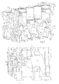
- Fig. 1 shows in cross-section a combustion engine 1 of reciprocating type intended for a motor vehicle.
- the combustion engine has four cylinders 3 with associated pistons 5. These are in a conventional manner interconnected via a common crank shaft 7 by means of connecting rods 9.
- the crank shaft 7 is supported by a plurality of eccentric crankshaft bearings 11 arranged in the cylinder block of the combustion engine, which allow for rotation of the crank shaft 7 in the cylinder block.
- the force that is generated in the cylinders 3 is transmitted, via the connecting rods 9, to the crank shaft 7, and is forwarded to a not shown coupling/transmission for the operation of the wheels of the motor vehicle, but possibly also to a cam shaft for opening/closing of the valves of the reciprocating engine, or other devices that may take advantage of the energy produced by the reciprocating engine.
- eccentric crank shaft bearings 11 eccentric supporting of the crank shaft and implies that the centre axis of the crank shaft do not coincide with the centre axis that connects the different crank shaft bearings. Since the crank shaft bearings also are pivotally arranged in the cylinder block, it will be possible to change the position of the crank shaft 7 in the radial direction, and primarily in the vertical direction, i.e. the distance between the crank shaft and the cylinder head. Thus, the volume of the combustion space can be changed at the same time as the cylinder stroke is maintained, which thus affects the compression ratio of the reciprocating engine 1.
- each crank shaft bearing 11 is performed by means of a not shown device, but it is well known to the skilled man to use different types of devices to perform this type of pivoting, see for example FR 2 825 756.
- FR 2 825 756 By varying the position of the crank shaft 7 in this way, the performance of the engine is improved since the compression ratio can be optimised as function of the operation conditions.
- Fig. 2 shows an enlargement of the reciprocating engine in fig. 1, with focus on the left part of the reciprocating engine shown in fig. 1.
- a crank shaft end 13 is supported in one of the eccentric crank shaft bearings 11 and comprises a cylindrical part 13 that forms an axially extended corbelling of the crank shaft end.
- the cylindrical part forms part of a crank elbow.
- a circular crank shaft flange 17 is also rotatably arranged, wherein the flange 17 can rotate with respect to the cylinder block.
- the flange 17 is not eccentrically supported in the cylinder block. Consequently, the position of the flange 17 in the radial direction will be constant, and thereby also its distance to the cylinder head.
- crank shaft end 13 will be movable in the radial direction in relation to the flange 17. This occurs when the eccentric crank shaft bearings 11 are pivoted, when adjusting the compression ratio as desired, in dependence of the actual operation condition.
- the crank shaft flange 17 and the crank shaft end 13 are arranged adjacent to each other, as seen in axial direction, with their respective centre axis positioned in planes that are parallel to each other.
- the crank shaft flange 17 is positioned "down stream" the crank shaft end 13, as seen in the force transmission direction.
- the flange 17 and the crank shaft end 13 together form, when they are arranged adjacent to each other as depicted in fig. 2, one in an axial direction extended cavity 19 having a cylindrical surface.
- This cavity 19 is comprised of a first cavity portion 23 arranged in the flange 17 and a second cavity portion 25 arranged in the crank shaft end 13. As disclosed in fig. 2, the second cavity portion 25 extends through the whole of the cylindrical corbelling and further into the crank elbow of the crank shaft.
- a coupling arrangement is required to transmit a torque from the crank shaft to the crank shaft flange for transmittance to the transmission of the motor vehicle. It is also required that the torque can be transmitted between the crank shaft and the crank shaft flange even though their centre axes are situated in different planes.
- a coupling arrangement 27 comprises two coupling halves 29, 31 which are mutually connected by means of an element 33 in the shape of a splined coupling 33.
- the first coupling half 29 comprises a part 30 consisting of four pins which together form a cross.
- the cross shaped part 30 is by means of two of its pins connected to the coupling half 29, which is substantially fork shaped, while the remaining two pins are connected to the cylindrical inner surface of the cavity portion 23 of the crank shaft flange 17.
- Each pin is moreover pivotally supported (by means of not shown needle bearings) in the coupling half 29 and in the crank shaft flange 17, respectively. Consequently, the coupling half 29 will be tiltable in an arbitrary radial direction in respect of crank shaft flange 17.
- the second coupling half 31 comprises a part 32 consisting of four pins which together forms a cross.
- the cross-shaped part 32 is by means of two of its pins connected to the coupling half 31, which is substantially fork shaped, while the other two pins are connected to the cylindrical inner surface of the cavity portion 25 of the crank shaft end.
- Each pin is moreover pivotally supported (by means of not shown needle bearings) in the coupling half 31 and in the crank shaft end 13, respectively. Consequently, the coupling half 31 will be tiltable in an arbitrary radial direction in respect of crank shaft flange 17.
- the coupling halves 29, 31 are mutually connected by means of the splined coupling 33, which ensures that a torque can be transmitted between the coupling halves 29, 31, but also ensures that a certain axial movement of the respective coupling half is allowed during the load of the crank shaft. Due to this arrangement, when adjusting the position of the crank shaft 7 in the radial direction, the coupling arrangement 27, with its tiltable coupling halves 29, 31, will adjust to and ensure a force transmission independent of the mutual positions of the crank shaft end 13 and the crank shaft flange 17. At the same time, the external dimensions of the engine are not affected since the coupling arrangement is disposed in the cavity 19.
Landscapes
- Engineering & Computer Science (AREA)
- Chemical & Material Sciences (AREA)
- Combustion & Propulsion (AREA)
- Mechanical Engineering (AREA)
- General Engineering & Computer Science (AREA)
- Transmission Devices (AREA)
- Output Control And Ontrol Of Special Type Engine (AREA)
- Shafts, Cranks, Connecting Bars, And Related Bearings (AREA)
Applications Claiming Priority (2)
| Application Number | Priority Date | Filing Date | Title |
|---|---|---|---|
| SE0400423A SE526640C2 (sv) | 2004-02-24 | 2004-02-24 | Kolvmotor för ett motorfordon innefattande ett kopplingsarrangemang för överföring av vridmoment från en vevaxelände till en i cylinderblocket lagrad vevaxelfläns |
| SE0400423 | 2004-02-24 |
Publications (1)
| Publication Number | Publication Date |
|---|---|
| EP1568867A2 true EP1568867A2 (de) | 2005-08-31 |
Family
ID=31989591
Family Applications (1)
| Application Number | Title | Priority Date | Filing Date |
|---|---|---|---|
| EP05100931A Withdrawn EP1568867A2 (de) | 2004-02-24 | 2005-02-10 | Brennkraftmaschine |
Country Status (3)
| Country | Link |
|---|---|
| US (1) | US7213545B2 (de) |
| EP (1) | EP1568867A2 (de) |
| SE (1) | SE526640C2 (de) |
Cited By (1)
| Publication number | Priority date | Publication date | Assignee | Title |
|---|---|---|---|---|
| WO2009083257A1 (de) * | 2007-12-31 | 2009-07-09 | Fev Motorentechnik Gmbh | Vcr-gelenkwellenabtrieb |
Families Citing this family (4)
| Publication number | Priority date | Publication date | Assignee | Title |
|---|---|---|---|---|
| JP4497018B2 (ja) * | 2005-04-14 | 2010-07-07 | トヨタ自動車株式会社 | 可変圧縮比内燃機関 |
| US20110033234A1 (en) * | 2007-03-28 | 2011-02-10 | Edward Charles Mendler | Power take-off coupling |
| KR101090801B1 (ko) * | 2009-06-30 | 2011-12-08 | 현대자동차주식회사 | 가변 압축비 장치 |
| EP2992200B1 (de) * | 2013-05-03 | 2019-07-03 | Blackstock, Scott | Motor mit variablem verdichtungsverhältnis |
Citations (2)
| Publication number | Priority date | Publication date | Assignee | Title |
|---|---|---|---|---|
| US6443106B1 (en) | 1999-03-24 | 2002-09-03 | Fev Motorentechnik Gmbh | Coupling element connecting two parallel, spaced shafts for varying their position relative to one another |
| FR2825756A1 (fr) | 2001-06-11 | 2002-12-13 | Roger Lecal | Systeme pour modifier le p.m.h. d'un mecanisme bielle/manivelle |
-
2004
- 2004-02-24 SE SE0400423A patent/SE526640C2/sv not_active IP Right Cessation
-
2005
- 2005-02-10 EP EP05100931A patent/EP1568867A2/de not_active Withdrawn
- 2005-02-24 US US11/067,634 patent/US7213545B2/en not_active Expired - Fee Related
Patent Citations (2)
| Publication number | Priority date | Publication date | Assignee | Title |
|---|---|---|---|---|
| US6443106B1 (en) | 1999-03-24 | 2002-09-03 | Fev Motorentechnik Gmbh | Coupling element connecting two parallel, spaced shafts for varying their position relative to one another |
| FR2825756A1 (fr) | 2001-06-11 | 2002-12-13 | Roger Lecal | Systeme pour modifier le p.m.h. d'un mecanisme bielle/manivelle |
Cited By (2)
| Publication number | Priority date | Publication date | Assignee | Title |
|---|---|---|---|---|
| WO2009083257A1 (de) * | 2007-12-31 | 2009-07-09 | Fev Motorentechnik Gmbh | Vcr-gelenkwellenabtrieb |
| CN101910583B (zh) * | 2007-12-31 | 2013-12-11 | Fev有限公司 | Vcr万向轴传动装置 |
Also Published As
| Publication number | Publication date |
|---|---|
| SE526640C2 (sv) | 2005-10-18 |
| SE0400423D0 (sv) | 2004-02-24 |
| US20050183680A1 (en) | 2005-08-25 |
| SE0400423L (sv) | 2005-08-25 |
| US7213545B2 (en) | 2007-05-08 |
Similar Documents
| Publication | Publication Date | Title |
|---|---|---|
| EP2176531B1 (de) | Mechanismus für hubkolbenmotoren | |
| US5007385A (en) | Crankless engine | |
| US7584724B2 (en) | Variable compression ratio dual crankshaft engine | |
| CN101550875B (zh) | 可变压缩率装置 | |
| JP5266228B2 (ja) | 改良された対向ピストン燃焼エンジン | |
| US6968751B2 (en) | Axial piston machines | |
| JPH08502802A (ja) | 連接棒のないピストンを備える流体作動機械 | |
| EP2021584B1 (de) | Verbrennungsmotor | |
| EP1674692B1 (de) | Brennkraftmaschine | |
| JP2009516123A (ja) | 圧縮比可変の往復ピストン式内燃機関 | |
| US7213545B2 (en) | Reciprocating engine | |
| US10184395B2 (en) | Multi-joint crank drive of an internal combustion engine, and corresponding internal combustion engine | |
| EP2923053B1 (de) | Brennkraftmaschine mit asymmetrischer auslasszeitsteuerung | |
| CN101985899B (zh) | 动力单元组发动机 | |
| CN105723071A (zh) | 内燃机的多连杆曲柄连杆机构以及用于运行多连杆曲柄连杆机构的方法 | |
| JP3106171B2 (ja) | クランクレスエンジン機構 | |
| WO2014062068A1 (en) | An internal combustion engine | |
| CN110671199B (zh) | 可变压缩比机构与发动机 | |
| US10718262B2 (en) | Variable stroke constant compression ratio engine | |
| CN201818364U (zh) | 动力单元组发动机 | |
| WO2017001986A1 (en) | Atkinson-cycle reciprocating engine | |
| EP3708770A1 (de) | Brennkraftmaschine mit gegenüberliegenden kolben und einer zentralen antriebswelle | |
| US4708106A (en) | Acute angle crankarm transmitting reciprocating motion in a rotary fashion | |
| CN110657024A (zh) | 可变压缩比机构与发动机 | |
| KR100375603B1 (ko) | 엔진용 크랭크 샤프트 |
Legal Events
| Date | Code | Title | Description |
|---|---|---|---|
| PUAI | Public reference made under article 153(3) epc to a published international application that has entered the european phase |
Free format text: ORIGINAL CODE: 0009012 |
|
| AK | Designated contracting states |
Kind code of ref document: A2 Designated state(s): AT BE BG CH CY CZ DE DK EE ES FI FR GB GR HU IE IS IT LI LT LU MC NL PL PT RO SE SI SK TR |
|
| AX | Request for extension of the european patent |
Extension state: AL BA HR LV MK YU |
|
| STAA | Information on the status of an ep patent application or granted ep patent |
Free format text: STATUS: THE APPLICATION IS DEEMED TO BE WITHDRAWN |
|
| 18D | Application deemed to be withdrawn |
Effective date: 20070901 |