EP1568564A1 - Railway carriage provided with an emergency exit assembly - Google Patents
Railway carriage provided with an emergency exit assembly Download PDFInfo
- Publication number
- EP1568564A1 EP1568564A1 EP05003833A EP05003833A EP1568564A1 EP 1568564 A1 EP1568564 A1 EP 1568564A1 EP 05003833 A EP05003833 A EP 05003833A EP 05003833 A EP05003833 A EP 05003833A EP 1568564 A1 EP1568564 A1 EP 1568564A1
- Authority
- EP
- European Patent Office
- Prior art keywords
- railway carriage
- climbing aid
- window opening
- wall
- carriage
- Prior art date
- Legal status (The legal status is an assumption and is not a legal conclusion. Google has not performed a legal analysis and makes no representation as to the accuracy of the status listed.)
- Withdrawn
Links
- 230000009194 climbing Effects 0.000 claims abstract description 52
- 230000000717 retained effect Effects 0.000 claims description 7
- 230000006378 damage Effects 0.000 description 2
- 230000000712 assembly Effects 0.000 description 1
- 238000000429 assembly Methods 0.000 description 1
Images

Classifications
-
- E—FIXED CONSTRUCTIONS
- E06—DOORS, WINDOWS, SHUTTERS, OR ROLLER BLINDS IN GENERAL; LADDERS
- E06C—LADDERS
- E06C9/00—Ladders characterised by being permanently attached to fixed structures, e.g. fire escapes
- E06C9/06—Ladders characterised by being permanently attached to fixed structures, e.g. fire escapes movably mounted
- E06C9/14—Ladders characterised by being permanently attached to fixed structures, e.g. fire escapes movably mounted with non-rigid longitudinal members, e.g. rope or chain ladders, ladders of the lazy-tongs type
-
- B—PERFORMING OPERATIONS; TRANSPORTING
- B61—RAILWAYS
- B61D—BODY DETAILS OR KINDS OF RAILWAY VEHICLES
- B61D19/00—Door arrangements specially adapted for rail vehicles
- B61D19/02—Door arrangements specially adapted for rail vehicles for carriages
- B61D19/023—Emergency exits
Definitions
- the present invention relates in general to an emergency exit assembly for a vehicle, in particular an emergency exit suitable for railed passenger vehicles such as trains, buses, and trams, especially for double-decker vehicles such as double-decker carriages of railway vehicles.
- emergency exit assemblies are known in the art. Their general purpose is to allow the passengers of that vehicle to leave the vehicle quickly and easily in case of an emergency.
- emergency exits are provided in the form of doors or windows which are closed when not in use. In the event of an emergency, the exit then either opens by itself or it can be opened manually. The opening then allows the passengers to leave the part of the vehicle they are in.
- DE 100 26 117 discloses an emergency exit window for a vehicle. However, there is no teaching of any exit aid or climbing aid, allowing passengers to reach the ground from the exit.
- SU 1418140 A1 discloses a single-deck railway vehicle with emergency exit through a window opening.
- evacuation means such as a rope-ladder are stored in a housing fixed to the bottom side of the top of a small table, which is arranged below the window opening and hinged to the wall of the vehicle.
- this table top is swung through the window opening and serves as an egress platform, whereas the housing is opened, the ladder unfolded, suspended on the pivoted table top, and used to climb down towards the track.
- Such an arrangement is rather complicated and heavy, so the table needs additional supporting means in the normal mode and a strong hinge mechanism in the emergency mode.
- this arrangement seems to be limited to single-deck railway vehicles since the usable space beneath a table and within a housing as described is limited and cannot take a ladder long enough to escape from an upper emergency exit of a double-deck railway vehicle.
- SU 1274950 A1 discloses an emergency exit device for a railway vehicle, which comprises a three-step telescopic ladder.
- this ladder In the normal operational mode this ladder is folded and fixed outside the vehicle in front of a window opening, the ladder's lower end being hinged to the wall of the vehicle below the opening and its upper end fixed above the window opening by a holder.
- the upper end of the ladder In case of an emergency, the upper end of the ladder is released from the holder, swung downwards at the hinge and unfolded.
- This arrangement is, in its storage position, rather disadvantageous because it limits the view through the windows.
- the ladder adds to the overall cross-section of the car body, which must fit into a structural gauge of the vehicle.
- such an arrangement is also not suitable for double-
- exit opening is located high above the ground or in another safe area so that the passengers face considerable difficulty when attempting to leave the vehicle.
- exit aids have been developed which are designed to facilitate the actual exit from the vehicle.
- the most common solution to the problem of evacuating passengers from great heights is to provide slides. Slides are often used in emergency exits of aeroplanes, but have also been suggested for railway vehicles.
- double-decker vehicles may include two decks or more than two decks.
- the term double-decker is used for convenience to denote any such multi-compartment vehicle.
- Many double-decker vehicles only have one or two entrance areas for passengers, usually located on the lower deck. In order to reach the other compartments or other decks, the passengers first board the vehicle at the entrance and then make their way to the other compartments through the inside of the vehicle, e.g. via stairs.
- top deck is accessible only via the lower deck as noted.
- passengers are forced to descend first to the lower deck before they can leave the carriage. This significantly increases the safety risks for both the passengers descending from the top deck and the passengers already present on the lower deck.
- German utility model DE 297 23 978 U1 discloses an emergency exit for double-decker trains comprising a flap, which pivots around a pivot point.
- This document also discloses an exit aid, in particular a rigid ladder, which may be in the form of a telescopic ladder.
- the ladder may either be designed to be hooked onto the opening at one end, or it may be integrated in the flap. It can also be located in a seat underneath the flap.
- the disadvantage of this emergency exit is that it is designed to lead not to the outside of the train but merely to the lower deck. This means that passengers are unable to leave the train directly in case of an emergency.
- a railway carriage comprising:
- the window opening is preferably covered with a closure.
- the type of closure is not critical, it may be any type of window, hatch, flap or similar.
- the climbing aid has two positions: a stored position when the climbing aid is not in use, and an extended position.
- the climbing aid has a first, distal, end and a second, proximal, end. The first end can be removed from the stored position and moved out of the emergency exit opening so that it provides an aid for passengers to climb out of the vehicle and down to the ground or onto some other safe area outside the vehicle.
- the second end is designed so that it is automatically fixed to the vehicle when the climbing aid is in the extended position.
- the term "automatically” means that no separate action is required to fix the second end of the climbing aid to the vehicle when extending the climbing aid.
- the second end of the climbing aid is moveable but retained in such a way that it automatically shifts into a fixed position once the climbing aid is extended.
- the assembly comprises a means for retaining the second end of the climbing end, when the first end is moved into the extended position.
- the retainer may be a plate with one or more holes through which the climbing aid is passed when being extended.
- the second end of the climbing aid is formed to be too large to pass the plate, and is thus retained.
- the second end may be free to slide along a support attached to the vehicle, for example along a bar or rail. A retainer prevents the second end from leaving the support.
- a preferred example of the climbing aid is a rope, rope ladder, chain ladder or the like having a free first end whereas the second end is retained by a retainer which has an opening just large enough for the rope or ladder or the like, but not large enough for a knot or for an object attached to the climbing aid to increase its size at the second end.
- the retainer is attached to the vehicle. In the stored position, the second end of the climbing aid is moveable with respect to its retainer.
- its first or free end is taken from its stored position and moved out of the emergency exit opening so that it extends down towards the ground from the emergency exit opening. In this extended position, the weight of the rope or ladder causes the second end to automatically move until it is retained by the retainer.
- the knot or enlarged second end will cause the rope or ladder to be fixed to the vehicle without human intervention. This has the great advantage of avoiding human error such as might occur when a rope or ladder has to be manually affixed to the exit opening.
- the second end of the climbing aid is attached to the vehicle by an attachment point.
- the attachment point is positioned so that the first end of the climbing aid can be moved into the extended position.
- this attachment point is near the emergency exit opening, more preferably inside a compartment in which the climbing aid is stored. In this way, the climbing aid is not accessible when not in use and is therefore safe from misuse.
- the attachment can be effected by any means known to the skilled person.
- the climbing aid can be welded or glued to the vehicle, or it can be attached using fasteners such as a screw, bolt, nail or other fasteners that are known to the person skilled in the art.
- the climbing aid is designed so that it can be extended to a suitable length when in use and be reduced in length when not in use so that it can be stored easily.
- it is flexible and/or collapsible and/or telescopic, so that it can easily be stored in a compartment near the emergency exit opening when not in use.
- the climbing aid provides an aid for passengers wishing to climb out of the vehicle by themselves. It may comprise ropes, rope ladders, poles, and telescope ladders.
- a rope can mean any elongated flexible object which can be gripped and used as a climbing aid. If a rope is used, it preferably has gripping aids such as knots, lugs, eyelets or similar.
- Another preferred embodiment of the climbing aid of the present invention is a rope ladder.
- the rope ladder comprises suitable rungs which passengers can step on when climbing down the ladder.
- the climbing aid consists of a rigid, non-flexible material which can be folded up to reduce its length.
- the climbing aid can be folded up in a telescopic manner.
- the telescopic climbing aid can be a pole or telescopic ladder.
- the backbone is designed so that its individual pieces can at least partly slide into one another.
- the climbing aid such as a ladder, can comprise two or more sections hinged together, so as to be foldable.
- the climbing aid is stored in a separate compartment near the opening.
- the compartment for storing the climbing aid can have any suitable form, such as a bag, a box, a recess in the wall etc.
- it is disposed in a recess in the wall, floor or ceiling of the vehicle.
- the emergency exit may be in the position of a window along a row of passenger seats or between passenger seats.
- side tables are provided. The underside of the tables can house the compartment for the climbing aid.
- the opening may be rendered accessible to persons such as passengers or members of the rescue services by any suitable means.
- the opening may be accessible at all times. However, it may be preferred to render the opening accessible only in case of an emergency. Action to provide access could be taken manually, for example by the driver of the vehicle, when an emergency is detected.
- the vehicle may comprise an automated system able to detect an emergency, such as a fire or the like, which will activate the opening for access by persons.
- a railway vehicle for example a railway carriage, comprising an emergency exit assembly according to the invention.
- the railway vehicle is designed as a double-decker carriage.
- the emergency exit assembly is preferably disposed on the top deck of the double-decker carriage.
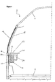
- Figure 1 depicts a cross-section through the top deck of a double-decker railway carriage and shows a side cross-sectional view of an emergency exit assembly (2) of the present invention in the stored position.
- the emergency exit (2) is located in a wall (4) of the top deck of the carriage. Also shown is the floor (6) of the top deck.
- the emergency exit opening (8) is closed by an emergency exit window (10).
- Underneath the window (10), a storage compartment (12) for storing the climbing aid (14) is attached to the inside of the wall (4) of the carriage.
- the climbing aid (14) is a rope ladder which is folded up inside the storage compartment (12).
- the rope ladder (14) has a first end (16) which is free, i.e. not attached to the vehicle or retained.
- the rope ladder (14) also has a second end (18), which is attached to the inside of the wall (4) of the railway carriage at an attachment point (20).
- the storage compartment (12) is covered by a lid (22), which can be lifted to provide access to the rope ladder.
- the lid (22) is part of a table (24) which covers a second compartment (26) which can be used for other purposes, e.g. as a rubbish container.
- the emergency exit is opened, giving access to an opening in the vehicle.
- the compartment holding the climbing aid is opened and the climbing aid lowered out of the opening towards the ground with its free first end (16), the other end (20) being attached to the wall of the vehicle.
- FIG. 2 shows the same cross-section through the top deck of a railway carriage, except that in this drawing the emergency exit window (10) has been opened giving access to an opening (8) in the wall (4) of the carriage.
- the lid (22) covering the compartment (12) has been opened and the first end (16, first end not shown in Figure 2) of the rope ladder (14) has been lowered out of the window opening (8, 10).
- the rope ladder (14) is still attached to the wall (4) of the carriage by an attachment point (20), which in this case is a bolt securing the rope ladder (14) (bolt not shown).
- the rope ladder (14) hangs down along the outside wall of the carriage and provides a climbing aid for passengers evacuating the carriage through the emergency exit.
- the rope ladder (14) of Figures 1 and 2 can be replaced by other exit aids, such as one or more ropes (preferably knotted), a hinged or telescopic ladder or a pole.
- the emergency exit assembly may be in installed and used in any kind of railway carriages, including trams and the like.
Landscapes
- Engineering & Computer Science (AREA)
- Mechanical Engineering (AREA)
- Business, Economics & Management (AREA)
- Emergency Management (AREA)
- Ladders (AREA)
- Vehicle Step Arrangements And Article Storage (AREA)
Abstract
Description
- The present invention relates in general to an emergency exit assembly for a vehicle, in particular an emergency exit suitable for railed passenger vehicles such as trains, buses, and trams, especially for double-decker vehicles such as double-decker carriages of railway vehicles.
- A variety of emergency exit assemblies are known in the art. Their general purpose is to allow the passengers of that vehicle to leave the vehicle quickly and easily in case of an emergency. Usually, emergency exits are provided in the form of doors or windows which are closed when not in use. In the event of an emergency, the exit then either opens by itself or it can be opened manually. The opening then allows the passengers to leave the part of the vehicle they are in.
- Especially in larger vehicles, problems with leaving the vehicle often arise after the exit has been opened.
- DE 100 26 117 discloses an emergency exit window for a vehicle. However, there is no teaching of any exit aid or climbing aid, allowing passengers to reach the ground from the exit.
- SU 1418140 A1 discloses a single-deck railway vehicle with emergency exit through a window opening. Under normal operational conditions evacuation means such as a rope-ladder are stored in a housing fixed to the bottom side of the top of a small table, which is arranged below the window opening and hinged to the wall of the vehicle. In an emergency this table top is swung through the window opening and serves as an egress platform, whereas the housing is opened, the ladder unfolded, suspended on the pivoted table top, and used to climb down towards the track. Such an arrangement is rather complicated and heavy, so the table needs additional supporting means in the normal mode and a strong hinge mechanism in the emergency mode. Moreover, this arrangement seems to be limited to single-deck railway vehicles since the usable space beneath a table and within a housing as described is limited and cannot take a ladder long enough to escape from an upper emergency exit of a double-deck railway vehicle.
- SU 1274950 A1 discloses an emergency exit device for a railway vehicle, which comprises a three-step telescopic ladder. In the normal operational mode this ladder is folded and fixed outside the vehicle in front of a window opening, the ladder's lower end being hinged to the wall of the vehicle below the opening and its upper end fixed above the window opening by a holder. In case of an emergency, the upper end of the ladder is released from the holder, swung downwards at the hinge and unfolded. This arrangement is, in its storage position, rather disadvantageous because it limits the view through the windows. Moreover, the ladder adds to the overall cross-section of the car body, which must fit into a structural gauge of the vehicle. Furthermore, there is the risk of destruction by external (stationary) parts passing by. If one of the holders fails while the vehicle is moving, the ladder is in danger of being detached, causing damage to the vehicle itself or to another vehicle passing by, or even hurting people. Finally, such an arrangement is also not suitable for double-deck railway vehicles.
- Frequently, the exit opening is located high above the ground or in another safe area so that the passengers face considerable difficulty when attempting to leave the vehicle. For this reason, exit aids have been developed which are designed to facilitate the actual exit from the vehicle. The most common solution to the problem of evacuating passengers from great heights is to provide slides. Slides are often used in emergency exits of aeroplanes, but have also been suggested for railway vehicles.
- Some vehicles present additional problems, in particular those which comprise more than one passenger compartment, the compartments being located on top of each other, herein referred to as double-decker vehicles. These may include two decks or more than two decks. The term double-decker is used for convenience to denote any such multi-compartment vehicle. Many double-decker vehicles only have one or two entrance areas for passengers, usually located on the lower deck. In order to reach the other compartments or other decks, the passengers first board the vehicle at the entrance and then make their way to the other compartments through the inside of the vehicle, e.g. via stairs.
- A problem frequently encountered with double-decker railway carriages is that the top deck is accessible only via the lower deck as noted. In case of an emergency, the passengers are forced to descend first to the lower deck before they can leave the carriage. This significantly increases the safety risks for both the passengers descending from the top deck and the passengers already present on the lower deck.
- German utility model DE 297 23 978 U1 discloses an emergency exit for double-decker trains comprising a flap, which pivots around a pivot point. This document also discloses an exit aid, in particular a rigid ladder, which may be in the form of a telescopic ladder. The ladder may either be designed to be hooked onto the opening at one end, or it may be integrated in the flap. It can also be located in a seat underneath the flap. The disadvantage of this emergency exit is that it is designed to lead not to the outside of the train but merely to the lower deck. This means that passengers are unable to leave the train directly in case of an emergency.
- There is a need for a simple emergency exit assembly that can be used in particular in railway carriages with a higher deck such as double-deckers, which is simple, compact, robust and easy to use.
- According to the invention, there is provided a railway carriage comprising:
- a wall;
- a window opening located in the wall and leading to the outside of the railway carriage; and
- an emergency exit assembly comprising:
- a climbing aid which has a proximal end located inside the railway carriage and a distal free end moveable through the window opening between a stored position inside the railway carriage and an extended position towards the ground outside of the railway carriage; and
- a storage compartment for storing the climbing aid while the free end is in the stored position, wherein the storage compartment is fixed relative to the wall inside the railway carriage underneath the window opening and is covered by a lid , which can be lifted to provide access to the climbing aid.
- The window opening is preferably covered with a closure. The type of closure is not critical, it may be any type of window, hatch, flap or similar.
- The climbing aid has two positions: a stored position when the climbing aid is not in use, and an extended position. The climbing aid has a first, distal, end and a second, proximal, end. The first end can be removed from the stored position and moved out of the emergency exit opening so that it provides an aid for passengers to climb out of the vehicle and down to the ground or onto some other safe area outside the vehicle.
- The second end is designed so that it is automatically fixed to the vehicle when the climbing aid is in the extended position. For the purposes of the present invention, the term "automatically" means that no separate action is required to fix the second end of the climbing aid to the vehicle when extending the climbing aid.
- In a preferred embodiment, the second end of the climbing aid is moveable but retained in such a way that it automatically shifts into a fixed position once the climbing aid is extended. In this embodiment, the assembly comprises a means for retaining the second end of the climbing end, when the first end is moved into the extended position. In its simplest form, the retainer may be a plate with one or more holes through which the climbing aid is passed when being extended. The second end of the climbing aid is formed to be too large to pass the plate, and is thus retained. In other arrangements, the second end may be free to slide along a support attached to the vehicle, for example along a bar or rail. A retainer prevents the second end from leaving the support.
- A preferred example of the climbing aid is a rope, rope ladder, chain ladder or the like having a free first end whereas the second end is retained by a retainer which has an opening just large enough for the rope or ladder or the like, but not large enough for a knot or for an object attached to the climbing aid to increase its size at the second end. The retainer is attached to the vehicle. In the stored position, the second end of the climbing aid is moveable with respect to its retainer. When the rope or ladder is being used as an emergency exit aid, its first or free end is taken from its stored position and moved out of the emergency exit opening so that it extends down towards the ground from the emergency exit opening. In this extended position, the weight of the rope or ladder causes the second end to automatically move until it is retained by the retainer. The knot or enlarged second end will cause the rope or ladder to be fixed to the vehicle without human intervention. This has the great advantage of avoiding human error such as might occur when a rope or ladder has to be manually affixed to the exit opening.
- In another preferred embodiment, the second end of the climbing aid is attached to the vehicle by an attachment point. This means that, rather than being moveable and retained, the second end of the climbing aid is already fixed to the vehicle even when in the stored position. The attachment point is positioned so that the first end of the climbing aid can be moved into the extended position. Preferably, this attachment point is near the emergency exit opening, more preferably inside a compartment in which the climbing aid is stored. In this way, the climbing aid is not accessible when not in use and is therefore safe from misuse. The attachment can be effected by any means known to the skilled person. The climbing aid can be welded or glued to the vehicle, or it can be attached using fasteners such as a screw, bolt, nail or other fasteners that are known to the person skilled in the art.
- The climbing aid is designed so that it can be extended to a suitable length when in use and be reduced in length when not in use so that it can be stored easily. Preferably, it is flexible and/or collapsible and/or telescopic, so that it can easily be stored in a compartment near the emergency exit opening when not in use.
- The climbing aid provides an aid for passengers wishing to climb out of the vehicle by themselves. It may comprise ropes, rope ladders, poles, and telescope ladders.
- For the purposes of the present invention, a rope can mean any elongated flexible object which can be gripped and used as a climbing aid. If a rope is used, it preferably has gripping aids such as knots, lugs, eyelets or similar. Another preferred embodiment of the climbing aid of the present invention is a rope ladder. The rope ladder comprises suitable rungs which passengers can step on when climbing down the ladder.
- In an alternative preferred embodiment, the climbing aid consists of a rigid, non-flexible material which can be folded up to reduce its length. Preferably, the climbing aid can be folded up in a telescopic manner. The telescopic climbing aid can be a pole or telescopic ladder. In the preferred case of a telescopic ladder, the backbone is designed so that its individual pieces can at least partly slide into one another. Alternatively, the climbing aid, such as a ladder, can comprise two or more sections hinged together, so as to be foldable.
- The climbing aid is stored in a separate compartment near the opening. The compartment for storing the climbing aid can have any suitable form, such as a bag, a box, a recess in the wall etc. Preferably, it is disposed in a recess in the wall, floor or ceiling of the vehicle. It can also be part of other internal architecture of the vehicle. For example, the emergency exit may be in the position of a window along a row of passenger seats or between passenger seats. Preferably, side tables are provided. The underside of the tables can house the compartment for the climbing aid.
- The opening may be rendered accessible to persons such as passengers or members of the rescue services by any suitable means. The opening may be accessible at all times. However, it may be preferred to render the opening accessible only in case of an emergency. Action to provide access could be taken manually, for example by the driver of the vehicle, when an emergency is detected. Alternatively, the vehicle may comprise an automated system able to detect an emergency, such as a fire or the like, which will activate the opening for access by persons.
- Another aspect of the present invention relates to a railway vehicle, for example a railway carriage, comprising an emergency exit assembly according to the invention. In a preferred embodiment, the railway vehicle is designed as a double-decker carriage. The emergency exit assembly is preferably disposed on the top deck of the double-decker carriage.
- The present invention will now be further illustrated by means of the specific, but not limiting, embodiments depicted in the figures.
- Figure 1:
- depicts an emergency exit assembly of the present invention in the stored position.
- Figure 2:
- depicts an emergency exit assembly of the present invention in the extended position.
- Figure 1 depicts a cross-section through the top deck of a double-decker railway carriage and shows a side cross-sectional view of an emergency exit assembly (2) of the present invention in the stored position. The emergency exit (2) is located in a wall (4) of the top deck of the carriage. Also shown is the floor (6) of the top deck. The emergency exit opening (8) is closed by an emergency exit window (10). Underneath the window (10), a storage compartment (12) for storing the climbing aid (14) is attached to the inside of the wall (4) of the carriage. In the embodiment shown in Figure 1, the climbing aid (14) is a rope ladder which is folded up inside the storage compartment (12). The rope ladder (14) has a first end (16) which is free, i.e. not attached to the vehicle or retained. This first end (16) can be removed from the storage compartment. The rope ladder (14) also has a second end (18), which is attached to the inside of the wall (4) of the railway carriage at an attachment point (20). The storage compartment (12) is covered by a lid (22), which can be lifted to provide access to the rope ladder. In this particular embodiment, the lid (22) is part of a table (24) which covers a second compartment (26) which can be used for other purposes, e.g. as a rubbish container.
- In case of an emergency, the emergency exit is opened, giving access to an opening in the vehicle. The compartment holding the climbing aid is opened and the climbing aid lowered out of the opening towards the ground with its free first end (16), the other end (20) being attached to the wall of the vehicle.
- Figure 2 shows the same cross-section through the top deck of a railway carriage, except that in this drawing the emergency exit window (10) has been opened giving access to an opening (8) in the wall (4) of the carriage. The lid (22) covering the compartment (12) has been opened and the first end (16, first end not shown in Figure 2) of the rope ladder (14) has been lowered out of the window opening (8, 10). At the second end (18), the rope ladder (14) is still attached to the wall (4) of the carriage by an attachment point (20), which in this case is a bolt securing the rope ladder (14) (bolt not shown). The rope ladder (14) hangs down along the outside wall of the carriage and provides a climbing aid for passengers evacuating the carriage through the emergency exit.
- The rope ladder (14) of Figures 1 and 2 can be replaced by other exit aids, such as one or more ropes (preferably knotted), a hinged or telescopic ladder or a pole.
- While the specific embodiments of the present invention have been described as installed in the compartment of a railway carriage, it will be appreciated that the emergency exit assembly may be in installed and used in any kind of railway carriages, including trams and the like.
Claims (11)
- A railway carriage comprising:a wall (4);a window opening (8) located in the wall (4) and leading to the outside of the railway carriage; andan emergency exit assembly (2) comprising:a climbing aid (14) which has an proximal end (18) located inside the railway carriage and a distal free end (16) moveable through the window opening (8) between a stored position inside the railway carriage and a extended position towards the ground outside of the railway carriage, anda storage compartment for storing the climbing aid while the free end (16) is in the stored position, wherein the storage compartment is fixed relative to the wall (4) inside the railway carriage underneath the window opening (8) and is covered by a lid (22) which can be lifted to provide access to the climbing aid (14).
- The railway carriage of claim 1, wherein the railway carriage is a double-decker carriage, with the window opening (8) and the emergency exit assembly (2) being located in an upper deck of the carriage.
- The railway carriage of claim 1 or claim 2, wherein the climbing aid (14) is flexible and/or collapsible and/or telescopic.
- The railway carriage of any one of the preceding claims, wherein the climbing aid (14) is a rope, a rope ladder, a telescopic pole or a telescopic ladder.
- The railway carriage of any one of the preceding claims, wherein the window opening (8) is rendered accessible only in an emergency.
- The railway carriage of claim 5, wherein the window opening (8) is rendered accessible automatically in an emergency.
- The railway carriage of any one of the preceding claims, wherein the storage compartment (12) is attached to the inside of the wall (4).
- The railway carriage of any one of the preceding claims, wherein the lid of the storage compartment (12) is part of a table (24).
- The railway carriage of claim 8, wherein the table covers a second compartment (26) which can be used for other purposes, in particular as a rubbish container.
- The railway carriage of any one of the preceding claims, wherein the proximal end (18) of the climbing aid (14) is permanently attached to the inside of the wall (4) at an attachment point (20).
- The railway carriage of any one of claims 1 to 10, wherein the proximal end (18) of the climbing aid (14) is retained by a retainer attached to the railway carriage and automatically fixed to the railway carriage while the distal end is in the extended position.
Applications Claiming Priority (2)
| Application Number | Priority Date | Filing Date | Title |
|---|---|---|---|
| GB0404119 | 2004-02-25 | ||
| GB0404119A GB0404119D0 (en) | 2004-02-25 | 2004-02-25 | Emergency exit assembly |
Publications (1)
| Publication Number | Publication Date |
|---|---|
| EP1568564A1 true EP1568564A1 (en) | 2005-08-31 |
Family
ID=32050799
Family Applications (1)
| Application Number | Title | Priority Date | Filing Date |
|---|---|---|---|
| EP05003833A Withdrawn EP1568564A1 (en) | 2004-02-25 | 2005-02-23 | Railway carriage provided with an emergency exit assembly |
Country Status (2)
| Country | Link |
|---|---|
| EP (1) | EP1568564A1 (en) |
| GB (1) | GB0404119D0 (en) |
Cited By (2)
| Publication number | Priority date | Publication date | Assignee | Title |
|---|---|---|---|---|
| CN118401425A (en) * | 2021-12-14 | 2024-07-26 | 西门子交通奥地利有限责任公司 | Passenger rail vehicle with emergency exit |
| WO2024156409A1 (en) * | 2023-01-24 | 2024-08-02 | Siemens Mobility GmbH | Windscreen module with emergency exit |
Citations (7)
| Publication number | Priority date | Publication date | Assignee | Title |
|---|---|---|---|---|
| GB191325882A (en) * | 1913-11-12 | 1914-11-12 | Joseph Rafferty | Improvements in Means for Facilitating Exit from Railway Vehicles. |
| US3503340A (en) * | 1967-09-11 | 1970-03-31 | George A Warren | Auto transporting passenger train |
| SU1418140A1 (en) * | 1987-03-31 | 1988-08-23 | Калининский вагоностроительный завод им.М.И.Калинина | Emergency exit for passengers of railway carriage |
| WO1996032564A1 (en) * | 1995-04-10 | 1996-10-17 | Christensen Lane J | Emergency escape ladder assembly |
| US6015027A (en) * | 1999-05-06 | 2000-01-18 | Banks; Frank | Escape ladder assembly |
| DE19850933A1 (en) * | 1998-11-05 | 2000-05-11 | Schliess Und Sicherungssysteme | Emergency exit device for rail vehicles |
| US6102155A (en) * | 1998-10-14 | 2000-08-15 | Hood; Joshua H. | Combined window and emergency escape ladder |
-
2004
- 2004-02-25 GB GB0404119A patent/GB0404119D0/en not_active Ceased
-
2005
- 2005-02-23 EP EP05003833A patent/EP1568564A1/en not_active Withdrawn
Patent Citations (7)
| Publication number | Priority date | Publication date | Assignee | Title |
|---|---|---|---|---|
| GB191325882A (en) * | 1913-11-12 | 1914-11-12 | Joseph Rafferty | Improvements in Means for Facilitating Exit from Railway Vehicles. |
| US3503340A (en) * | 1967-09-11 | 1970-03-31 | George A Warren | Auto transporting passenger train |
| SU1418140A1 (en) * | 1987-03-31 | 1988-08-23 | Калининский вагоностроительный завод им.М.И.Калинина | Emergency exit for passengers of railway carriage |
| WO1996032564A1 (en) * | 1995-04-10 | 1996-10-17 | Christensen Lane J | Emergency escape ladder assembly |
| US6102155A (en) * | 1998-10-14 | 2000-08-15 | Hood; Joshua H. | Combined window and emergency escape ladder |
| DE19850933A1 (en) * | 1998-11-05 | 2000-05-11 | Schliess Und Sicherungssysteme | Emergency exit device for rail vehicles |
| US6015027A (en) * | 1999-05-06 | 2000-01-18 | Banks; Frank | Escape ladder assembly |
Cited By (2)
| Publication number | Priority date | Publication date | Assignee | Title |
|---|---|---|---|---|
| CN118401425A (en) * | 2021-12-14 | 2024-07-26 | 西门子交通奥地利有限责任公司 | Passenger rail vehicle with emergency exit |
| WO2024156409A1 (en) * | 2023-01-24 | 2024-08-02 | Siemens Mobility GmbH | Windscreen module with emergency exit |
Also Published As
| Publication number | Publication date |
|---|---|
| GB0404119D0 (en) | 2004-03-31 |
Similar Documents
| Publication | Publication Date | Title |
|---|---|---|
| AU2000236528B2 (en) | Device for carrying out work in an elevator shaft | |
| US10173595B1 (en) | Portable truck step | |
| US4216725A (en) | Combination door and emergency stairway exit | |
| ES2222317T3 (en) | AIRCRAFT AND AIRCRAFT DOOR EQUIPPED WITH SUCH DOOR. | |
| US6102155A (en) | Combined window and emergency escape ladder | |
| US6874597B2 (en) | Vehicle sleeper compartment bunk bed ladder | |
| US20120006618A1 (en) | Cement industry gangway and safety cage | |
| US20040118635A1 (en) | Apparatus for evacuating people from a high building in emergency | |
| US6447044B1 (en) | Sheltered aircraft supply vehicle | |
| US5845741A (en) | Escape apparatus | |
| JP2019001458A (en) | Vehicle and evacuation unit | |
| CN106740637A (en) | A passenger car escape window device | |
| US4031583A (en) | Inflatable emergency equipment deployment device | |
| ES2943251T3 (en) | rail vehicle | |
| ITRM20070530A1 (en) | "LIFTING VEHICLE" | |
| KR100969560B1 (en) | Wheelchair loading and unloading device for railway vehicles | |
| JP3195089U (en) | Evacuation ladder | |
| JP2001063571A (en) | Underfloor strorage type emergency escape device for vehicle | |
| CN115230759B (en) | Automatic escape device for skytrain and skytrain | |
| US6029771A (en) | Collapsible fire escape ladder with anti-tip restraint seat | |
| US20010002633A1 (en) | Emergency passenger evacuation chute and chute/slide combination for aircraft | |
| RU99755U1 (en) | METRO WAGON EQUIPPED WITH A PASSENGER EVACUATION DEVICE | |
| EP1011586B1 (en) | Vehicle lift apparatus | |
| AU2006100845A4 (en) | Emergency evacuation system for track vehicle | |
| US1083939A (en) | Foldable stair for sleeping-car berths. |
Legal Events
| Date | Code | Title | Description |
|---|---|---|---|
| PUAI | Public reference made under article 153(3) epc to a published international application that has entered the european phase |
Free format text: ORIGINAL CODE: 0009012 |
|
| AK | Designated contracting states |
Kind code of ref document: A1 Designated state(s): AT BE BG CH CY CZ DE DK EE ES FI FR GB GR HU IE IS IT LI LT LU MC NL PL PT RO SE SI SK TR |
|
| AX | Request for extension of the european patent |
Extension state: AL BA HR LV MK YU |
|
| 17P | Request for examination filed |
Effective date: 20060131 |
|
| AKX | Designation fees paid |
Designated state(s): AT BE BG CH CY CZ DE DK EE ES FI FR GB GR HU IE IS IT LI LT LU MC NL PL PT RO SE SI SK TR |
|
| 17Q | First examination report despatched |
Effective date: 20081222 |
|
| STAA | Information on the status of an ep patent application or granted ep patent |
Free format text: STATUS: THE APPLICATION IS DEEMED TO BE WITHDRAWN |
|
| 18D | Application deemed to be withdrawn |
Effective date: 20100521 |