EP1568342B2 - Disposable diaper - Google Patents
Disposable diaper Download PDFInfo
- Publication number
- EP1568342B2 EP1568342B2 EP03812298.2A EP03812298A EP1568342B2 EP 1568342 B2 EP1568342 B2 EP 1568342B2 EP 03812298 A EP03812298 A EP 03812298A EP 1568342 B2 EP1568342 B2 EP 1568342B2
- Authority
- EP
- European Patent Office
- Prior art keywords
- facing surface
- zones
- slip
- waist
- wings
- Prior art date
- Legal status (The legal status is an assumption and is not a legal conclusion. Google has not performed a legal analysis and makes no representation as to the accuracy of the status listed.)
- Expired - Lifetime
Links
Images


Classifications
-
- A—HUMAN NECESSITIES
- A61—MEDICAL OR VETERINARY SCIENCE; HYGIENE
- A61F—FILTERS IMPLANTABLE INTO BLOOD VESSELS; PROSTHESES; DEVICES PROVIDING PATENCY TO, OR PREVENTING COLLAPSING OF, TUBULAR STRUCTURES OF THE BODY, e.g. STENTS; ORTHOPAEDIC, NURSING OR CONTRACEPTIVE DEVICES; FOMENTATION; TREATMENT OR PROTECTION OF EYES OR EARS; BANDAGES, DRESSINGS OR ABSORBENT PADS; FIRST-AID KITS
- A61F13/00—Bandages or dressings; Absorbent pads
- A61F13/15—Absorbent pads, e.g. sanitary towels, swabs or tampons for external or internal application to the body; Supporting or fastening means therefor; Tampon applicators
- A61F13/15203—Properties of the article, e.g. stiffness or absorbency
-
- A—HUMAN NECESSITIES
- A61—MEDICAL OR VETERINARY SCIENCE; HYGIENE
- A61F—FILTERS IMPLANTABLE INTO BLOOD VESSELS; PROSTHESES; DEVICES PROVIDING PATENCY TO, OR PREVENTING COLLAPSING OF, TUBULAR STRUCTURES OF THE BODY, e.g. STENTS; ORTHOPAEDIC, NURSING OR CONTRACEPTIVE DEVICES; FOMENTATION; TREATMENT OR PROTECTION OF EYES OR EARS; BANDAGES, DRESSINGS OR ABSORBENT PADS; FIRST-AID KITS
- A61F13/00—Bandages or dressings; Absorbent pads
- A61F13/15—Absorbent pads, e.g. sanitary towels, swabs or tampons for external or internal application to the body; Supporting or fastening means therefor; Tampon applicators
- A61F13/45—Absorbent pads, e.g. sanitary towels, swabs or tampons for external or internal application to the body; Supporting or fastening means therefor; Tampon applicators characterised by the shape
- A61F13/49—Absorbent pads, e.g. sanitary towels, swabs or tampons for external or internal application to the body; Supporting or fastening means therefor; Tampon applicators characterised by the shape specially adapted to be worn around the waist, e.g. diapers, nappies
- A61F13/494—Absorbent pads, e.g. sanitary towels, swabs or tampons for external or internal application to the body; Supporting or fastening means therefor; Tampon applicators characterised by the shape specially adapted to be worn around the waist, e.g. diapers, nappies characterised by edge leakage prevention means
- A61F13/49466—Absorbent pads, e.g. sanitary towels, swabs or tampons for external or internal application to the body; Supporting or fastening means therefor; Tampon applicators characterised by the shape specially adapted to be worn around the waist, e.g. diapers, nappies characterised by edge leakage prevention means the edge leakage prevention means being at the waist region
-
- A—HUMAN NECESSITIES
- A61—MEDICAL OR VETERINARY SCIENCE; HYGIENE
- A61F—FILTERS IMPLANTABLE INTO BLOOD VESSELS; PROSTHESES; DEVICES PROVIDING PATENCY TO, OR PREVENTING COLLAPSING OF, TUBULAR STRUCTURES OF THE BODY, e.g. STENTS; ORTHOPAEDIC, NURSING OR CONTRACEPTIVE DEVICES; FOMENTATION; TREATMENT OR PROTECTION OF EYES OR EARS; BANDAGES, DRESSINGS OR ABSORBENT PADS; FIRST-AID KITS
- A61F13/00—Bandages or dressings; Absorbent pads
- A61F13/15—Absorbent pads, e.g. sanitary towels, swabs or tampons for external or internal application to the body; Supporting or fastening means therefor; Tampon applicators
- A61F13/56—Supporting or fastening means
- A61F13/5622—Supporting or fastening means specially adapted for diapers or the like
- A61F13/5633—Supporting or fastening means specially adapted for diapers or the like open type diaper
- A61F13/5638—Supporting or fastening means specially adapted for diapers or the like open type diaper adjustable open type diapers
Definitions
- the present invention relates to a disposable diaper.
- the front and rear wings placed upon each other along lateral zones of front and rear waist regions are reliably prevented from shifting and/or twisting relative to each other and leakage of bodily discharges is also reliably prevented.
- any effective measure can not be found in this diaper of well known art to make these wings placed upon each other smoothly follow movement of the wearer's body. Consequently, the lateral zones of the front and rear waist regions put on the wearer's body are relatively stiff and hardly stretchable, inevitably creating a feeling of discomfort against the wearer.
- the present invention provides the open-type disposable diaper of independent claim 1 and the open-type disposable diaper of independent claim 2.
- an open-type disposable diaper configured by a front waist region, a rear waist region and a crotch region extending between these two waist regions, these regions having a body facing surface and an undergarment facing surface opposed to the body facing surface, the diaper being contoured by front and rear end zones extending in parallel to each other in a waist-surrounding direction and transversely opposite lateral zones extending in parallel to each other in back-and-forth direction crossing the waist-surrounding direction, the transversely opposite lateral zones in one of the front and rear waist regions being formed with first wings extending in the waist-surrounding direction, the first wings are respectively provided on the body facing surface with first fastener means and the undergarment facing surface in the other of the front and rear waist regions being provided with second fastener means on which the first fastener means are detachably anchored.
- the invention further comprises the first wings being elastically stretchable in the waist-surrounding direction and the undergarment facing surface in the other waist region being provided in a vicinity of the second fastener means with anti-slip zones each adapted to come in contact with the body facing surface of the wings and to exhibit an average kinetic frictional force of 0.5 N or higher under a load of 58.23 g/9 cm 2 and an average kinetic frictional force of 5 N or lower under a load of 340 g/9 cm 2 relative to the body facing surface as the first fastener means are anchored on the second fastener means, wherein elastic fibers made of a plastic elastomer and having a fiber length of 5 to 100 mm are mixed with inelastic fibers made of a thermoplastic material having a fiber length of 5 to 100 mm in said anti-slip zones or continuous elastic fibers made of a plastic elastomer are mixed with continuous inelastic fibers made of a thermoplastic material in said anti-slip zones.
- the present invention includes the following embodiments.
- the average kinetic frictional force is measured using the method prescribed paragraph 3.1 of JIS (Japanese Industrial Standard) P 8147.
- a weight of 3 cm x 3 cm and adapted to apply a load of 58.23 g/9 cm 2 or 340 g/9 cm 2 is used to carry out this measurement.
- Moving velocity of the weight is set to 10 cm/min.
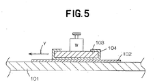
- a movable plate 103 has its lower surface of 3 cm x 3 cm and a total weight of this movable plate 103 is adjusted by a weight W so that a load of 58.23 g/9 cm 2 or 340 g/9 cm 2 is applied to the lower surface. Such movable plate is used as the weight. Then the movable plate 103 is pulled in a direction indicated by an arrow Y and thereby moved by 5 cm. An average kinetic frictional force (unit: N) is calculated from values of frictional force measured in the course of this movement.
- Fig. 1 is a perspective view of an open-type disposable diaper 1 according to the present invention as put on a wearer's body and Fig. 2 is a developed and partially cutaway plan view of the disposable diaper 1.
- a center line C bisects a width of the diaper 1.
- the diaper 1 is of open-type and has a surface 2 facing a wearer's body and a surface 3 facing a wearer's undergarment. As viewed in a back-and-forth direction, the diaper 1 is composed of a front waist region 6, a rear waist region 7 and a crotch region 8 extending between these waist regions 6, 7.
- the diaper 1 is contoured by a pair of waist-surrounding upper end zones 11 and a pair of lateral zones 12 extending in the back-and-forth direction (i.e., in vertical direction as viewed in Fig. 2 ) so as to cross these waist-surrounding upper end zones 11.
- Fig. 1 illustrates the diaper 1 with the surface 2 facing the wearer's body inside and with the surface 3 facing the wearer's undergarment outside.
- Fig. 2 illustrates the diaper 1 with the undergarment facing surface 3 on upper side and with the body facing surface 2 on a rear side.
- the diaper 1 has a rectangular body section 16, a pair of front wings 17 extending in a waist-surrounding direction from transversely opposite lateral zones of the front waist region 6 in the body section 16 and a pair of rear wings 18 extending in the waist-surrounding direction from transversely opposite lateral zones of the rear waist region 7 in the body section 16.
- a pair of tape fasteners 23 extends from distal end portions 21 of the respective rear winds 18, each of these tape fasteners 23 including a hook member 22 (See Fig. 3 ) which is one component constituting the so-called mechanical fastener commonly known, for example, of the trademark "VELCRO".
- These tape fasteners 23 extend in the waist-surrounding direction and serve as first fastener means.
- the front waist region 6 in the body section 16 is formed on the undergarment facing surface 3 with a landing zone 26 which is provided with a loop member 24 (See Fig. 3 ), the other component constituting the mechanical fastener.
- This landing zone 26 serves as second fastener means.
- the front waist region 6 may be placed against the belly side of the wearer, the rear waist region 7 may be placed against the wearer's back side, then the rear wings 18 may be placed from outside upon the front wings 17, the tape fasteners 23 may be pulled in the waist-surrounding direction and anchored on the landing zone 26.
- the tape fasteners 23 and the landing zone 26 are substantially fixed one to another without an anxiety that these tape fasteners 23 and landing zone 26 might be shifted relative to one another or peeled off one from another.
- the diaper 1 Upon wearing the diaper in this manner, the diaper 1 is formed with a waist-hole 10a and a pair of leg-holes 10b.
- the body section 16 shown by Fig. 2 comprises a liquid-pervious topsheet 32 defining the body facing surface 2, a liquid-impervious backsheet 33 defining the undergarment facing surface 3 and a liquid-absorbent core 34 interposed between these two sheets 32, 33. Portions of the top- and backsheets 32, 33 extending outward beyond a peripheral edge of the core 34 are joined together by means of adhesion or heat-sealing.
- waist elastic members 36 extending in the waist-surrounding direction in stretched state and leg elastic members 37 extending over the crotch region 8 into the front and rear waist regions 6, 7 in stretched state are interposed between the top- and backsheets 32, 33 and joined to the inner surface of at least one the top- and backsheets 32, 33 by means of adhesives (not shown).
- Fig. 3 is a sectional view taken along line III-III in Fig. 1 .
- Each of the front wings 17 shown in Fig. 3 is formed by sheet materials such as a nonwoven fabric, woven fabric or plastic film, preferably by a breathable sheet material and more preferably by a breathable and sweat-absorbent sheet material.
- Each of the front wings 17 has a distal end portion 41 being remote from the center line C (See Fig. 2 ) in the waist-surrounding direction and a proximal end portion 42 located aside toward the center line C and joined to the surface 3 facing the wearer's undergarment of the body section 16 by means of heat-sealing or adhesion.
- the proximal end portion 42 immediately overlies the associated leg elastic members 37 so as to cover end zone of these members 37 or overlies extension of the associated leg elastic members 37 as viewed in the back-and-forth direction (See Fig. 2 ).
- the proximal end portion 42 is formed in its zone adjacent the landing zone 26 with a anti-slip zone 44 as indicated by a plurality of spots in Fig. 2 .
- Each of the front wings 17 is formed in its zone located aside toward the distal end portion 41 relative to the anti-slip zone 44 with a slip zone 46.
- the anti-slip zone 44 has a dimension A in a range of 5 to 70 mm in the waist-surrounding direction and the slip zone 46 has a dimension B in a range of 0 to 50 mm in the waist-surrounding direction.
- the anti-slip zone 44 exhibits an average kinetic frictional force of 0.5 N or higher under a load of 58.23 g/9 cm 2 and an average kinetic frictional force of 5 N or lower under a load of 340 g/9 cm 2 .
- the slip zone 46 exhibits an average kinetic frictional force lower than 0.5 N, preferably less than 0.3 N under a load of 58.23 g/9 cm 2 .
- the proximal end portions 42 thereof are joined to the transversely opposite lateral zones of the body section 16.
- the sheet-like fibrous mixture consisting of elastic fibers of styrene-based block copolymer such as SEBS, SEPS or SBBS having a fineness in a range of 0.1 to 3 dtex and inelastic fibers such as polypropylene-based fibers having a fineness in a range of 0.1 to 3 dtex may be placed upon and intermittently heat-sealed to desired zones of the nonwoven fabric.
- the zone having no fibrous mixture placed thereupon defines the slip zone 46.
- the elastic fibers constituting the fibrous mixture and exposed outward exhibits a sufficiently high average kinetic frictional force to resist slippage of a counterpart coming in contact with this anti-slip zone 44.
- the sheet material such as nonwoven fabric used to form the basic body of the front wing 17 preferably contains plastic ingredient exhibiting a substantially the same melting point as that of the inelastic fibers contained in the anti-slip zone 44. More preferably, the sheet material forming the basic body of the front wing 17 contains the exactly same plastic ingredient as the plastic ingredient of the inelastic fibers constituting the anti-slip zone 44.
- the elastic fibers and the inelastic fibers are mixed with each other at a weight ratio in a range of 8:2 to 5:5.
- the content of the elastic fibers in the mixture may be appropriately selected to vary a total area of the elastic fibers exposed toward the rear wings 18 destined to be put flat together with the anti-slip zones 44 when the diaper 1 is put on the wearer's body. Larger the total area of the elastic fibers is, higher the average kinetic frictional force of the anti-slip zones 44 is. On the contrary, larger the total area of the inelastic fibers is, lower the average kinetic frictional force of the anti-slip zones 44 is.
- the content of the elastic fibers in the fibrous mixture exceeds 80%, the average kinetic frictional force will be too high to raise the elastic fibers. If the content of the elastic fibers in the fibrous mixture is less than 50%, the average kinetic frictional force will be excessively low and consequently the rear wing 18 will be apt to slip relative to the associated front wing 17.
- the inelastic elastic fibers in the anti-slip zone 44 may be heat-sealed with the sheet material constituting the associated front wing 17 to ensure that the elastic fibers mixed with the inelastic fibers can be firmly fixed to the sheet material.
- the elastic fibers can be reliably fixed to the sheet material.
- the plastic ingredient contained in the sheet material forming the basic body of the front wing 17 is exactly the same as the plastic ingredient contained in the anti-slip zone 44, the elastic fibers can be more reliably fixed to the sheet material. In this way, it is not concerned that the elastic fibers might be raised on and/or falloff from the front wing 17 even when the elastic fibers is pulled by the rear wing 18 which is closely in contact with the elastic fibers.
- the elastic fibers as well as the inelastic fibers are used in form of continuous fibers or short fibers having a length of 5 to 100 mm.
- the anti-slip zone 44 formed by the continuous, elastic fibers and the continuous inelastic fibers is advantageous in that the anti-slip zone 44 can be prevented from fluffing but disadvantageous in that the mixing ratio of the elastic fibers and the inelastic fibers is not necessarily reflected in the exposed area ratio of the elastic fibers and the inelastic fibers. This is for the reason that it is difficult for these two types of continuous fibers to be evenly mixed and often one of them is more significantly exposed than the other.
- this fiber may be peeled off from the sheet material successively at the respective spots once this fiber has been peeled off at one of these spots.
- the anti-slip zone 44 formed by the elastic fibers and the inelastic fibers both of which are short fibers is inconvenient in that a plurality of heat-sealing spots must be provided to bond these two types of fibers to the sheet material forming the front wing 17.
- these two types of fibers can be easily mixed with each other and the mixing ratio of them is faithfully reflected in the exposed area ratio of the elastic fibers and the inelastic fibers.
- many distal ends of the short fibers present on the anti-slip zone 44 tightly enter into interstices of the fibers on the rear wing 18 put flat together with the associated front wing 17 and function to enhance the average kinetic frictional force.
- each of the rear wings 18 is elastically stretchable in the waist-surrounding direction and comprises a base sheet 61 formed by a nonwoven fabric made of plastic elastomer or film made of plastic elastomer and a fibrous layer 62 adapted to follow stretching and contraction of the base sheet 61 and to define a body facing surface and/or an undergarment facing surface of the base sheet 61.
- the fibrous layer 62 is preferably formed by inelastic fibers to ensure that the rear wing 18 is adequately slippery relative to the wearer's body. It is possible to form the fibrous layer 62 by crimped conjugate fibers or to provide the fibrous layer 62 with undulations in the waist-surrounding direction to ensure that the base sheet 61 can be smoothly stretched and contracted.
- the rear wings 17 are prevented from easily slipping relative to the respective anti-slip zones 44 since each of these anti-slip zones 44 has an average kinetic frictional force of 0.5 N or higher under a load of 58.23 g/9 cm 2 relative to the respective rear wings 18 put flat together with the respective the front wings 17.
- the front wing 17 is semi-fixed to the body facing surface 2 of the associated rear wing 18 by means of the anti-slip zone 44 provided on this front wing 17 and there is no fear that the front wing 17 might shift and/or twist relative to the associated rear wing 18 put flat together with the this front wing 18 during use of the diaper 1.
- the rear wing 18 is elastically stretchable under normal circumstances, it is difficult for the rear wing 18 to be easily stretchable in its zone placed upon the anti-slip zone 44.
- the rear wing 18 can be easily stretchable in its zone put flat together with the slip zone 46 and effectively function expected for the elastic rear wing 18.
- the average kinetic frictional force between the anti-slip zone 44 and the zone of the rear wing 18 put flat together therewith may be adjust to be 5 N or less under a load of 340 g/9 cm 2 to ensure that the rear wing 18 can slip relative to the associated anti-slip zone 44 as the rear wing 18 is intentionally pulled so that the front and rear waist regions 6, 7 might be counterchanged in the waist-surrounding direction. With a consequence, this diaper 1 is free from a problem that the presence of the anti-slip zones 44 might uncomfortably tighten the wearer's waist.
- the anti-slip zone 44 provided on the front wing 17 puts flat together with the associated rear wing 18 in such manner as has been described above and thereby prevents the front wing 17 as well as the rear wing 18 from being forcibly deformed.
- the range in which the anti-slip zone 44 is formed is not limited to that as illustrated but may be further enlarged.
- the anti-slip zone 44 may extend to the distal end portion 41 of the front wing 17 and, if desired, the anti-slip zone 44 may extend over the entire area of the backsheet 33.
- the distal end portion 41 of the front wing 17 is preferably left for formation of the slip-zone 46 to avoid the inconvenience that the elastic stretch of the rear wing 18 might be constricted.
- the anti-slip zone 44 is preferably formed immediately above or on extension of the leg elastic members 37 as will be seen in Figs. 1 and 2 so that the leg elastic members 37 cooperate with the rear wing 18 to form an elastically stretchable continuous ring adapted to surround the wearer's leg through the intermediary of the anti-slip zone 44. In this way, a fitness around the wearer's legs is improved and leak of bodily fluids can be prevented.
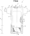
- Fig. 4 is a view similar to Fig. 2 , showing the disposable diaper 1 according to one preferred embodiment of the present invention.
- the diaper 1 according to this embodiment is distinguished from the previously described embodiment in that the diaper 1 has the rear wings 18 but not the front wings 17 and the transversely opposite lateral zones 12 rectilinearly extend from the crotch region 8 toward the front waist region 6, on one hand, and diverge in the waist-surrounding direction in the rear waist region 7 so as to form the rear wings 18.
- the anti-slip zones 44 are formed on the undergarment facing surface 3 of the lateral zones 12 in the front waist region 6 and the landing zone 26 is formed between these anti-slip zones 44.
- the rear wings 18 are similar to those illustrated by Fig. 2 and elastically stretchable.
- the present invention can be implemented in the form of a diaper wherein each of the front wings 17 is elastically stretchable in the waist-surrounding direction and provided with the tape fasteners 23 and the rear wings 18 are inelastic and provided on the undergarment facing surface 3 in the vicinity of the proximal end portions thereof with the anti-slip zones 44.
- the present invention can be implemented in the form of a diaper wherein the front wings are elastically stretchable and provided with the tape fasteners and there is provided none of the rear wings.
- the hook members 22 on the tape fasteners 23 serving as the first fastener means may be replaced by a pressure-sensitive adhesive and the backsheet 33 defining the undergarment facing surface 3 of the front waist region 6 serves as the second fastener means.
- the disposable diaper according to the present invention is in that the undergarment facing surface in one of the front and rear waist regions is provided with the anti-slip zones and the landing zone inside both anti-slip zones and the other of the front and rear waist regions is formed with the wings which are elastically stretchable in the waist-surrounding direction so that the undergarment facing surface of these wings may be put flat together with the anti-slip zones.
- Such an arrangement is effective to prevent the vicinity of the anti-slip zones and the wings put flat together therewith from shifting and twisting relative to each other.
- the portions of the wings put flat together with the anti-slip zones also are stretchable in the waist-surrounding direction as these wings are intentionally pulled in the waist-surrounding direction and therefore it is not concerned that these wings might uncomfortably tighten the wearer's waist.
Landscapes
- Health & Medical Sciences (AREA)
- Life Sciences & Earth Sciences (AREA)
- Engineering & Computer Science (AREA)
- Biomedical Technology (AREA)
- Heart & Thoracic Surgery (AREA)
- Vascular Medicine (AREA)
- Epidemiology (AREA)
- Animal Behavior & Ethology (AREA)
- General Health & Medical Sciences (AREA)
- Public Health (AREA)
- Veterinary Medicine (AREA)
- Absorbent Articles And Supports Therefor (AREA)
- Orthopedics, Nursing, And Contraception (AREA)
Abstract
Description
- The present invention relates to a disposable diaper.
- In open-type disposable diapers, it is well known to provide at least one of an undergarment facing surface of wings in a front waist region and a body facing surface of wings in rear waist region with anti-slip members in order to alleviate a slippage possibly occurring between these two facing surfaces. For example, Japanese Laid-Open Patent Application No.
1988-256702 A - With the diaper disclosed in the above-cited Application put on a wearer's body, the front and rear wings placed upon each other along lateral zones of front and rear waist regions are reliably prevented from shifting and/or twisting relative to each other and leakage of bodily discharges is also reliably prevented. However, any effective measure can not be found in this diaper of well known art to make these wings placed upon each other smoothly follow movement of the wearer's body. Consequently, the lateral zones of the front and rear waist regions put on the wearer's body are relatively stiff and hardly stretchable, inevitably creating a feeling of discomfort against the wearer.
- In view of the problem as has been described above, it is an object of the present invention to improve the above-described diaper of well known art so that a comfortable feeling to wear the diaper can be maintained even when transversely opposite lateral zones of front and rear waist regions are placed upon each other.
- The present invention provides the open-type disposable diaper of
independent claim 1 and the open-type disposable diaper ofindependent claim 2. - According to the present invention, there is an open-type disposable diaper configured by a front waist region, a rear waist region and a crotch region extending between these two waist regions, these regions having a body facing surface and an undergarment facing surface opposed to the body facing surface, the diaper being contoured by front and rear end zones extending in parallel to each other in a waist-surrounding direction and transversely opposite lateral zones extending in parallel to each other in back-and-forth direction crossing the waist-surrounding direction, the transversely opposite lateral zones in one of the front and rear waist regions being formed with first wings extending in the waist-surrounding direction, the first wings are respectively provided on the body facing surface with first fastener means and the undergarment facing surface in the other of the front and rear waist regions being provided with second fastener means on which the first fastener means are detachably anchored.
- The invention further comprises the first wings being elastically stretchable in the waist-surrounding direction and the undergarment facing surface in the other waist region being provided in a vicinity of the second fastener means with anti-slip zones each adapted to come in contact with the body facing surface of the wings and to exhibit an average kinetic frictional force of 0.5 N or higher under a load of 58.23 g/9 cm2 and an average kinetic frictional force of 5 N or lower under a load of 340 g/9 cm2 relative to the body facing surface as the first fastener means are anchored on the second fastener means, wherein
elastic fibers made of a plastic elastomer and having a fiber length of 5 to 100 mm are mixed with inelastic fibers made of a thermoplastic material having a fiber length of 5 to 100 mm in said anti-slip zones or
continuous elastic fibers made of a plastic elastomer are mixed with continuous inelastic fibers made of a thermoplastic material in said anti-slip zones. - The present invention includes the following embodiments.
- (1) The transversely opposite lateral zones in the crotch region is provided with leg elastic members extending further into the front and rear waist regions and the anti-slip zones are formed so as to cover parts of the leg elastic members or so as to lie on respective extensions of the leg elastic members in said back-and-forth direction.
- (2) The anti-slip zones are formed so as to be placed aside from the lateral zones toward a center line bisecting a width of the diaper and there are provided between respective the anti-slip zones and respective the lateral zones slip-zones each exhibiting an average kinetic frictional force lower than the average kinetic frictional force exhibited by each of the anti-slip zones.
- (3) A weight ratio of the elastic fibers and inelastic fibers in the anti-slip zone is in a range of 8:2 to 5:5.
- (4) The anti-slip zone is formed by bonding the elastic fibers and inelastic fibers mixed together to any one of a nonwoven fabric, woven fabric and film.
- (5) The inelastic fiber and the nonwoven fabric contain thermoplastic material having substantially same melting points while the woven fabric and film contain thermoplastic material having substantially the same melting points.
- (6) The lateral zones are partially broadened in the waist-surrounding direction to form second wings in the other waist region and the anti-slip zones are formed so as to be placed aside from distal end portions of the second wings toward the center line bisecting the width of the diaper.
- (7) The second wing is provided in a zone placed aside to the distal end portion with a slip-zone having the average kinetic frictional force lower than that of the anti-slip zone.
- In this invention, the average kinetic frictional force is measured using the method prescribed paragraph 3.1 of JIS (Japanese Industrial Standard) P 8147. A weight of 3 cm x 3 cm and adapted to apply a load of 58.23 g/9 cm2 or 340 g/9 cm2 is used to carry out this measurement. Moving velocity of the weight is set to 10 cm/min. This measuring method will be described more in detail with reference to
Fig. 5 of the accompanying drawings. An entire area of asheet 102 defining the body facing surface in the first wings of the disposable diaper is fixed to a smooth upper surface of afixed plate 101 by means of double-faced adhesive tape (not shown). Amovable plate 103 has its lower surface of 3 cm x 3 cm and a total weight of thismovable plate 103 is adjusted by a weight W so that a load of 58.23 g/9 cm2 or 340 g/9 cm2 is applied to the lower surface. Such movable plate is used as the weight. Then themovable plate 103 is pulled in a direction indicated by an arrow Y and thereby moved by 5 cm. An average kinetic frictional force (unit: N) is calculated from values of frictional force measured in the course of this movement. -
-
Fig. 1 is a perspective view of a disposable diaper according to the present invention; -
Fig. 2 is a developed plan view of the disposable diaper; -
Fig. 3 is a sectional view taken along line III-III inFig. 1 ; -
Fig. 4 is a view similar toFig. 2 , of a disposable diaper according to one preferred embodiment of the present invention; and -
Fig. 5 is a diagram illustrating a method for measurement of an average kinetic frictional force. - Details of a disposable diaper according to the present invention will be more fully understood from the description given hereunder with reference to the accompanying drawings.
-
Fig. 1 is a perspective view of an open-typedisposable diaper 1 according to the present invention as put on a wearer's body andFig. 2 is a developed and partially cutaway plan view of thedisposable diaper 1. Referring toFig. 2 , a center line C bisects a width of thediaper 1. Thediaper 1 is of open-type and has asurface 2 facing a wearer's body and asurface 3 facing a wearer's undergarment. As viewed in a back-and-forth direction, thediaper 1 is composed of afront waist region 6, arear waist region 7 and acrotch region 8 extending between thesewaist regions diaper 1 is contoured by a pair of waist-surroundingupper end zones 11 and a pair oflateral zones 12 extending in the back-and-forth direction (i.e., in vertical direction as viewed inFig. 2 ) so as to cross these waist-surroundingupper end zones 11.Fig. 1 illustrates thediaper 1 with thesurface 2 facing the wearer's body inside and with thesurface 3 facing the wearer's undergarment outside.Fig. 2 illustrates thediaper 1 with theundergarment facing surface 3 on upper side and with thebody facing surface 2 on a rear side. - As will be seen in
Fig. 2 , thediaper 1 has arectangular body section 16, a pair offront wings 17 extending in a waist-surrounding direction from transversely opposite lateral zones of thefront waist region 6 in thebody section 16 and a pair ofrear wings 18 extending in the waist-surrounding direction from transversely opposite lateral zones of therear waist region 7 in thebody section 16. A pair oftape fasteners 23 extends fromdistal end portions 21 of the respectiverear winds 18, each of thesetape fasteners 23 including a hook member 22 (SeeFig. 3 ) which is one component constituting the so-called mechanical fastener commonly known, for example, of the trademark "VELCRO". Thesetape fasteners 23 extend in the waist-surrounding direction and serve as first fastener means. Thefront waist region 6 in thebody section 16 is formed on theundergarment facing surface 3 with alanding zone 26 which is provided with a loop member 24 (SeeFig. 3 ), the other component constituting the mechanical fastener. Thislanding zone 26 serves as second fastener means. To putsuch diaper 1 on the wearer's body, thefront waist region 6 may be placed against the belly side of the wearer, therear waist region 7 may be placed against the wearer's back side, then therear wings 18 may be placed from outside upon thefront wings 17, thetape fasteners 23 may be pulled in the waist-surrounding direction and anchored on thelanding zone 26. Thetape fasteners 23 and thelanding zone 26 are substantially fixed one to another without an anxiety that thesetape fasteners 23 andlanding zone 26 might be shifted relative to one another or peeled off one from another. Upon wearing the diaper in this manner, thediaper 1 is formed with a waist-hole 10a and a pair of leg-holes 10b. - The
body section 16 shown byFig. 2 comprises a liquid-pervious topsheet 32 defining thebody facing surface 2, a liquid-impervious backsheet 33 defining theundergarment facing surface 3 and a liquid-absorbent core 34 interposed between these twosheets backsheets core 34 are joined together by means of adhesion or heat-sealing. Along the portions of the top- andbacksheets elastic members 36 extending in the waist-surrounding direction in stretched state and legelastic members 37 extending over thecrotch region 8 into the front andrear waist regions backsheets backsheets -
Fig. 3 is a sectional view taken along line III-III inFig. 1 . Each of thefront wings 17 shown inFig. 3 is formed by sheet materials such as a nonwoven fabric, woven fabric or plastic film, preferably by a breathable sheet material and more preferably by a breathable and sweat-absorbent sheet material. Each of thefront wings 17 has adistal end portion 41 being remote from the center line C (SeeFig. 2 ) in the waist-surrounding direction and aproximal end portion 42 located aside toward the center line C and joined to thesurface 3 facing the wearer's undergarment of thebody section 16 by means of heat-sealing or adhesion. Theproximal end portion 42 immediately overlies the associated legelastic members 37 so as to cover end zone of thesemembers 37 or overlies extension of the associated legelastic members 37 as viewed in the back-and-forth direction (SeeFig. 2 ). Theproximal end portion 42 is formed in its zone adjacent thelanding zone 26 with aanti-slip zone 44 as indicated by a plurality of spots inFig. 2 . Each of thefront wings 17 is formed in its zone located aside toward thedistal end portion 41 relative to theanti-slip zone 44 with aslip zone 46. In the illustrated embodiment, theanti-slip zone 44 has a dimension A in a range of 5 to 70 mm in the waist-surrounding direction and theslip zone 46 has a dimension B in a range of 0 to 50 mm in the waist-surrounding direction. Theanti-slip zone 44 exhibits an average kinetic frictional force of 0.5 N or higher under a load of 58.23 g/9 cm2 and an average kinetic frictional force of 5 N or lower under a load of 340 g/9 cm2. Theslip zone 46 exhibits an average kinetic frictional force lower than 0.5 N, preferably less than 0.3 N under a load of 58.23 g/9 cm2. - To realize the
front wings 17 having suchanti-slip zones 44, after a basic body of thefront wing 17 has been formed, for example, by a nonwoven fabric made of polypropylene continuous fibers having a fineness in range of 1 to 4 dtex and a basis weight in a range of 30 to 100g/m2, theproximal end portions 42 thereof are joined to the transversely opposite lateral zones of thebody section 16. The sheet-like fibrous mixture consisting of elastic fibers of styrene-based block copolymer such as SEBS, SEPS or SBBS having a fineness in a range of 0.1 to 3 dtex and inelastic fibers such as polypropylene-based fibers having a fineness in a range of 0.1 to 3 dtex may be placed upon and intermittently heat-sealed to desired zones of the nonwoven fabric. In each of suchfront wings 17, the zone having no fibrous mixture placed thereupon defines theslip zone 46. In theanti-slip zone 44, the elastic fibers constituting the fibrous mixture and exposed outward exhibits a sufficiently high average kinetic frictional force to resist slippage of a counterpart coming in contact with thisanti-slip zone 44. As will be understood from this example, the sheet material such as nonwoven fabric used to form the basic body of thefront wing 17 preferably contains plastic ingredient exhibiting a substantially the same melting point as that of the inelastic fibers contained in theanti-slip zone 44. More preferably, the sheet material forming the basic body of thefront wing 17 contains the exactly same plastic ingredient as the plastic ingredient of the inelastic fibers constituting theanti-slip zone 44. - The elastic fibers and the inelastic fibers are mixed with each other at a weight ratio in a range of 8:2 to 5:5. The content of the elastic fibers in the mixture may be appropriately selected to vary a total area of the elastic fibers exposed toward the
rear wings 18 destined to be put flat together with theanti-slip zones 44 when thediaper 1 is put on the wearer's body. Larger the total area of the elastic fibers is, higher the average kinetic frictional force of theanti-slip zones 44 is. On the contrary, larger the total area of the inelastic fibers is, lower the average kinetic frictional force of theanti-slip zones 44 is. If the content of the elastic fibers in the fibrous mixture exceeds 80%, the average kinetic frictional force will be too high to raise the elastic fibers. If the content of the elastic fibers in the fibrous mixture is less than 50%, the average kinetic frictional force will be excessively low and consequently therear wing 18 will be apt to slip relative to the associatedfront wing 17. The inelastic elastic fibers in theanti-slip zone 44 may be heat-sealed with the sheet material constituting the associatedfront wing 17 to ensure that the elastic fibers mixed with the inelastic fibers can be firmly fixed to the sheet material. When the plastic ingredient of these inelastic fibers has a melting point approximate to a melting point exhibited by the plastic ingredient in the sheet material forming the basic body of thefront wing 17, the elastic fibers can be reliably fixed to the sheet material. When the plastic ingredient contained in the sheet material forming the basic body of thefront wing 17 is exactly the same as the plastic ingredient contained in theanti-slip zone 44, the elastic fibers can be more reliably fixed to the sheet material. In this way, it is not concerned that the elastic fibers might be raised on and/or falloff from thefront wing 17 even when the elastic fibers is pulled by therear wing 18 which is closely in contact with the elastic fibers. - In the
anti-slip zone 44, the elastic fibers as well as the inelastic fibers are used in form of continuous fibers or short fibers having a length of 5 to 100 mm. Theanti-slip zone 44 formed by the continuous, elastic fibers and the continuous inelastic fibers is advantageous in that theanti-slip zone 44 can be prevented from fluffing but disadvantageous in that the mixing ratio of the elastic fibers and the inelastic fibers is not necessarily reflected in the exposed area ratio of the elastic fibers and the inelastic fibers. This is for the reason that it is difficult for these two types of continuous fibers to be evenly mixed and often one of them is more significantly exposed than the other. In addition to such problem, even when each of these continuous fibers is bonded at a plurality of spots thereof to the sheet material forming thefront wing 17, this fiber may be peeled off from the sheet material successively at the respective spots once this fiber has been peeled off at one of these spots. - The
anti-slip zone 44 formed by the elastic fibers and the inelastic fibers both of which are short fibers is inconvenient in that a plurality of heat-sealing spots must be provided to bond these two types of fibers to the sheet material forming thefront wing 17. However, these two types of fibers can be easily mixed with each other and the mixing ratio of them is faithfully reflected in the exposed area ratio of the elastic fibers and the inelastic fibers. In addition, should one of these short fibers be peeled off from thefront wing 17 at its bonded spot, there is no anxiety that any other fiber might be affected thereby to be easily peeled off from thefront wing 17. Furthermore, many distal ends of the short fibers present on theanti-slip zone 44 tightly enter into interstices of the fibers on therear wing 18 put flat together with the associatedfront wing 17 and function to enhance the average kinetic frictional force. - Referring to
Fig. 3 , each of therear wings 18 is elastically stretchable in the waist-surrounding direction and comprises abase sheet 61 formed by a nonwoven fabric made of plastic elastomer or film made of plastic elastomer and afibrous layer 62 adapted to follow stretching and contraction of thebase sheet 61 and to define a body facing surface and/or an undergarment facing surface of thebase sheet 61. Thefibrous layer 62 is preferably formed by inelastic fibers to ensure that therear wing 18 is adequately slippery relative to the wearer's body. It is possible to form thefibrous layer 62 by crimped conjugate fibers or to provide thefibrous layer 62 with undulations in the waist-surrounding direction to ensure that thebase sheet 61 can be smoothly stretched and contracted. - After the
diaper 1 of such construction has been put on the wearer's body with thetape fasteners 23 anchored on thelanding zone 26, therear wings 17 are prevented from easily slipping relative to the respectiveanti-slip zones 44 since each of theseanti-slip zones 44 has an average kinetic frictional force of 0.5 N or higher under a load of 58.23 g/9 cm2 relative to the respectiverear wings 18 put flat together with the respective thefront wings 17. In other words, thefront wing 17 is semi-fixed to thebody facing surface 2 of the associatedrear wing 18 by means of theanti-slip zone 44 provided on thisfront wing 17 and there is no fear that thefront wing 17 might shift and/or twist relative to the associatedrear wing 18 put flat together with the thisfront wing 18 during use of thediaper 1. While therear wing 18 is elastically stretchable under normal circumstances, it is difficult for therear wing 18 to be easily stretchable in its zone placed upon theanti-slip zone 44. However, therear wing 18 can be easily stretchable in its zone put flat together with theslip zone 46 and effectively function expected for the elasticrear wing 18. The average kinetic frictional force between theanti-slip zone 44 and the zone of therear wing 18 put flat together therewith may be adjust to be 5 N or less under a load of 340 g/9 cm2 to ensure that therear wing 18 can slip relative to the associatedanti-slip zone 44 as therear wing 18 is intentionally pulled so that the front andrear waist regions diaper 1 is free from a problem that the presence of theanti-slip zones 44 might uncomfortably tighten the wearer's waist. - The
anti-slip zone 44 provided on thefront wing 17 puts flat together with the associatedrear wing 18 in such manner as has been described above and thereby prevents thefront wing 17 as well as therear wing 18 from being forcibly deformed. The range in which theanti-slip zone 44 is formed is not limited to that as illustrated but may be further enlarged. For example, theanti-slip zone 44 may extend to thedistal end portion 41 of thefront wing 17 and, if desired, theanti-slip zone 44 may extend over the entire area of thebacksheet 33. However, thedistal end portion 41 of thefront wing 17 is preferably left for formation of the slip-zone 46 to avoid the inconvenience that the elastic stretch of therear wing 18 might be constricted. Theanti-slip zone 44 is preferably formed immediately above or on extension of the legelastic members 37 as will be seen inFigs. 1 and2 so that the legelastic members 37 cooperate with therear wing 18 to form an elastically stretchable continuous ring adapted to surround the wearer's leg through the intermediary of theanti-slip zone 44. In this way, a fitness around the wearer's legs is improved and leak of bodily fluids can be prevented. -
Fig. 4 is a view similar toFig. 2 , showing thedisposable diaper 1 according to one preferred embodiment of the present invention. Thediaper 1 according to this embodiment is distinguished from the previously described embodiment in that thediaper 1 has therear wings 18 but not thefront wings 17 and the transversely oppositelateral zones 12 rectilinearly extend from thecrotch region 8 toward thefront waist region 6, on one hand, and diverge in the waist-surrounding direction in therear waist region 7 so as to form therear wings 18. In the case of thisdiaper 1, theanti-slip zones 44 are formed on theundergarment facing surface 3 of thelateral zones 12 in thefront waist region 6 and thelanding zone 26 is formed between theseanti-slip zones 44. Therear wings 18 are similar to those illustrated byFig. 2 and elastically stretchable. - As a variant of the embodiment illustrated by
Figs. 1 and2 , the present invention can be implemented in the form of a diaper wherein each of thefront wings 17 is elastically stretchable in the waist-surrounding direction and provided with thetape fasteners 23 and therear wings 18 are inelastic and provided on theundergarment facing surface 3 in the vicinity of the proximal end portions thereof with theanti-slip zones 44. As a variant of the embodiment illustrated byFig. 4 , the present invention can be implemented in the form of a diaper wherein the front wings are elastically stretchable and provided with the tape fasteners and there is provided none of the rear wings. Furthermore, thehook members 22 on thetape fasteners 23 serving as the first fastener means may be replaced by a pressure-sensitive adhesive and thebacksheet 33 defining theundergarment facing surface 3 of thefront waist region 6 serves as the second fastener means. - The disposable diaper according to the present invention is in that the undergarment facing surface in one of the front and rear waist regions is provided with the anti-slip zones and the landing zone inside both anti-slip zones and the other of the front and rear waist regions is formed with the wings which are elastically stretchable in the waist-surrounding direction so that the undergarment facing surface of these wings may be put flat together with the anti-slip zones. Such an arrangement is effective to prevent the vicinity of the anti-slip zones and the wings put flat together therewith from shifting and twisting relative to each other. In addition, The portions of the wings put flat together with the anti-slip zones also are stretchable in the waist-surrounding direction as these wings are intentionally pulled in the waist-surrounding direction and therefore it is not concerned that these wings might uncomfortably tighten the wearer's waist.
Claims (9)
- An open-type disposable diaper configured by a front waist region, a rear waist region and a crotch region extending between said front and rear waist regions, said front and rear waist regions having a body facing surface and an undergarment facing surface opposed to said body facing surface, said diaper being contoured by front and rear end zones extending in parallel to each other in a waist-surrounding direction and transversely opposite lateral zones extending in parallel to each other in back-and-forth direction crossing said waist-surrounding direction, said transversely opposite lateral zones in one of said front and rear waist regions being formed with first wings extending in said waist-surrounding direction, said first wings are respectively provided on said body facing surface with first fastener means and said undergarment facing surface in the other of said front and rear waist regions being provided with second fastener means on which said first fastener means may be detachably anchored, said disposable diaper further comprising:said first wings being elastically stretchable in said waist-surrounding direction and said undergarment facing surface in said other waist region being provided in a vicinity of said second fastener means with anti-slip zones each adapted to come in contact with said body facing surface of said wings and to exhibit an average kinetic frictional force of 0.5 N or higher under a load of 58.23 g/9 cm2 and an average kinetic frictional force of 5 N or lower under a load of 340 g/9 cm2 relative to said body facing surface as said first fastener means being anchored on said second fastener means, whereinelastic fibers made of a plastic elastomer and having a fiber length of 5 to 100 mm are mixed with inelastic fibers made of a thermoplastic material having a fiber length of 5 to 100 mm in said anti-slip zones.
- An open-type disposable diaper configured by a front waist region, a rear waist region and a crotch region extending between said front and rear waist regions, said front and rear waist regions having a body facing surface and an undergarment facing surface opposed to said body facing surface, said diaper being contoured by front and rear end zones extending in parallel to each other in a waist-surrounding direction and transversely opposite lateral zones extending in parallel to each other in back-and-forth direction crossing said waist-surrounding direction, said transversely opposite lateral zones in one of said front and rear waist regions being formed with first wings extending in said waist-surrounding direction, said first wings are respectively provided on said body facing surface with first fastener means and said undergarment facing surface in the other of said front and rear waist regions being provided with second fastener means on which said first fastener means may be detachably anchored, said disposable diaper further comprising:said first wings being elastically stretchable in said waist-surrounding direction and said undergarment facing surface in said other waist region being provided in a vicinity of said second fastener means with anti-slip zones each adapted to come in contact with said body facing surface of said wings and to exhibit an average kinetic frictional force of 0.5 N or higher under a load of 58.23 g/9 cm2 and an average kinetic frictional force of 5 N or lower under a load of 340 g/9 cm2 relative to said body facing surface as said first fastener means being anchored on said second fastener means, whereincontinuous elastic fibers made of a plastic elastomer are mixed with continuous inelastic fibers made of a thermoplastic material in said anti-slip zones.
- The disposable diaper according to Claim 1 or Claim 2, wherein said transversely opposite lateral zones in said crotch region is provided with leg elastic members extending further into said front and rear waist regions and said anti-slip zones are formed so as to cover parts of said leg elastic members or so as to lie on respective extensions of said leg elastic members in said back-and-forth direction.
- The disposable diaper according to any preceding claim, wherein said anti-slip zones are formed so as to be placed aside from said lateral zones toward a center line bisecting a width of said diaper and there are provided between respective said anti-slip zones and respective said lateral zones slip-zones each exhibiting an average kinetic frictional force lower than said average kinetic frictional force exhibited by each of said anti-slip zones.
- The disposable diaper according to any preceding claim, wherein a weight ratio of said elastic fibers and inelastic fibers in said anti-slip zone is in a range of 8:2 to 5:5.
- The disposable diaper according to any preceding claim, wherein said anti-slip zone is formed by bonding said elastic fibers and inelastic fibers mixed together to any one of a nonwoven fabric, woven fabric and film.
- The disposable diaper according to Claim 6, wherein said inelastic fiber and said nonwoven fabric contain thermoplastic material having substantially the same melting points while said woven fabric and film contain a thermoplastic material having substantially the same melting points.
- The disposable diaper according to any preceding claim, wherein said lateral zones are partially broadened in said waist-surrounding direction to form second wings in said other waist region and said anti-slip zones are formed so as to be placed aside from distal end portions of said second wings toward said center line bisecting the width of said diaper.
- The disposable diaper according to Claim 8, wherein said second wing is provided in a zone placed aside to said distal end portion with a slip-zone having said average kinetic frictional force lower than that of said anti-slip zone.
Applications Claiming Priority (3)
| Application Number | Priority Date | Filing Date | Title |
|---|---|---|---|
| JP2002353001A JP4363840B2 (en) | 2002-12-04 | 2002-12-04 | Disposable diapers |
| JP2002353001 | 2002-12-04 | ||
| PCT/JP2003/015021 WO2004049999A1 (en) | 2002-12-04 | 2003-11-25 | Disposable diaper |
Publications (4)
| Publication Number | Publication Date |
|---|---|
| EP1568342A1 EP1568342A1 (en) | 2005-08-31 |
| EP1568342A4 EP1568342A4 (en) | 2009-09-30 |
| EP1568342B1 EP1568342B1 (en) | 2012-04-04 |
| EP1568342B2 true EP1568342B2 (en) | 2021-09-01 |
Family
ID=32463257
Family Applications (1)
| Application Number | Title | Priority Date | Filing Date |
|---|---|---|---|
| EP03812298.2A Expired - Lifetime EP1568342B2 (en) | 2002-12-04 | 2003-11-25 | Disposable diaper |
Country Status (11)
| Country | Link |
|---|---|
| US (1) | US7662137B2 (en) |
| EP (1) | EP1568342B2 (en) |
| JP (1) | JP4363840B2 (en) |
| KR (1) | KR100678445B1 (en) |
| CN (1) | CN100350890C (en) |
| AT (1) | ATE551981T1 (en) |
| AU (1) | AU2003302582B2 (en) |
| CA (1) | CA2507487C (en) |
| MY (1) | MY136164A (en) |
| TW (1) | TWI225395B (en) |
| WO (1) | WO2004049999A1 (en) |
Families Citing this family (28)
| Publication number | Priority date | Publication date | Assignee | Title |
|---|---|---|---|---|
| US20050267058A1 (en) * | 2001-05-18 | 2005-12-01 | Sirna Therapeutics, Inc. | RNA interference mediated inhibition of placental growth factor gene expression using short interfering nucleic acid (sINA) |
| JP4551125B2 (en) * | 2004-05-28 | 2010-09-22 | ユニ・チャーム株式会社 | Disposable pants-type wearing articles |
| EP1738729B1 (en) * | 2005-06-29 | 2013-11-06 | The Procter & Gamble Company | Laminate with indicia for an absorbent article |
| US20070225670A1 (en) * | 2006-03-14 | 2007-09-27 | Connell Thomas J | Diapers for improving male genital health and methods of using the same |
| JP2008142345A (en) * | 2006-12-11 | 2008-06-26 | Kao Corp | Disposable diapers |
| US8636710B2 (en) * | 2009-04-02 | 2014-01-28 | Kimberly-Clark Worldwide, Inc. | Fit maintenance system |
| CA2693130C (en) * | 2010-02-25 | 2012-10-09 | The Procter & Gamble Company | Absorbent article with improved garment-like character |
| JP5674345B2 (en) * | 2010-06-11 | 2015-02-25 | ユニ・チャーム株式会社 | Disposable wearing articles |
| ES2592530T3 (en) | 2011-06-17 | 2016-11-30 | Fiberweb, Llc | Multi-layer vapor permeable article, substantially waterproof |
| US10369769B2 (en) | 2011-06-23 | 2019-08-06 | Fiberweb, Inc. | Vapor-permeable, substantially water-impermeable multilayer article |
| PL2723568T3 (en) | 2011-06-23 | 2018-01-31 | Fiberweb Llc | Vapor permeable, substantially water impermeable multilayer article |
| US9765459B2 (en) | 2011-06-24 | 2017-09-19 | Fiberweb, Llc | Vapor-permeable, substantially water-impermeable multilayer article |
| US9615980B2 (en) | 2013-07-29 | 2017-04-11 | Kimberly-Clark Worldwide, Inc. | Absorbent article having a fastening system |
| US9265674B2 (en) | 2013-07-29 | 2016-02-23 | Kimberly-Clark Worldwide, Inc. | Absorbent article having a fastening system with low stiffness |
| US9480611B2 (en) | 2013-07-29 | 2016-11-01 | Kimberly-Clark Worldwide, Inc. | Absorbent article having a fastening system |
| US20150032078A1 (en) | 2013-07-29 | 2015-01-29 | Kimberly-Clark Worldwide, Inc. | Absorbent article having a fastening system with a visual cue |
| US9265673B2 (en) | 2013-07-29 | 2016-02-23 | Kimberly-Clark Worldwide, Inc. | Absorbent article having a fastening system |
| US9138362B2 (en) | 2013-07-29 | 2015-09-22 | Kimberly-Clark Worldwide, Inc. | Folded absorbent article with a fastening system |
| US9468569B2 (en) | 2013-11-04 | 2016-10-18 | Kimberly-Clark Worldwide, Inc. | Absorbent article having a fastening system and waist elastic with low load loss properties |
| US9339425B2 (en) | 2013-11-04 | 2016-05-17 | Kimberly-Clark Worldwide, Inc. | Absorbent article having a fastening system adapted to enhance gasketing |
| US9597237B2 (en) | 2013-12-31 | 2017-03-21 | Kimberly-Clark Worldwide, Inc | Absorbent article having a fastening system |
| US9980859B2 (en) | 2014-01-31 | 2018-05-29 | Kimberly-Clark Worldwide, Inc. | Absorbent article having a fastening system with improved flexibility |
| US9867743B2 (en) | 2014-04-30 | 2018-01-16 | Kimberly-Clark Worldwide, Inc. | Absorbent article having a primary fastening system and a secondary fastening system |
| WO2016069269A1 (en) | 2014-10-31 | 2016-05-06 | Kimberly-Clark Worldwide, Inc. | Absorbent article having a protected fastening system |
| US10716718B2 (en) * | 2015-06-26 | 2020-07-21 | First Quality Baby Products, Llc | Anti-skid material for ears or fastening tabs of absorbent article |
| CN108262846B (en) * | 2018-01-30 | 2023-10-13 | 上海歌灵新材料科技有限公司 | Production line for producing foaming microcrystal fireproof heat-preserving decorative integrated plate by utilizing smelting slag |
| JP6814250B2 (en) * | 2019-05-30 | 2021-01-13 | 花王株式会社 | Absorbent article |
| CN114305877B (en) * | 2020-09-30 | 2026-02-06 | 尤妮佳股份有限公司 | Absorbent article |
Family Cites Families (13)
| Publication number | Priority date | Publication date | Assignee | Title |
|---|---|---|---|---|
| US4699622A (en) * | 1986-03-21 | 1987-10-13 | The Procter & Gamble Company | Disposable diaper having an improved side closure |
| JPS63256702A (en) | 1987-04-10 | 1988-10-24 | 渡辺 修次 | Disposable diaper |
| US5151230A (en) * | 1990-10-01 | 1992-09-29 | Dinoflex Manufacturing Ltd. | Process for production of products formed of polymer bonded and granulated particles |
| JP2511455Y2 (en) * | 1992-05-27 | 1996-09-25 | ユニ・チャーム株式会社 | Diaper |
| JPH07100168A (en) * | 1993-10-06 | 1995-04-18 | Kao Corp | Disposable diapers |
| SE508628C2 (en) * | 1994-02-18 | 1998-10-19 | Sca Hygiene Prod Ab | Absorbent pants diaper |
| JPH10328237A (en) * | 1997-05-30 | 1998-12-15 | Uni Charm Corp | Disposable wearing article |
| US6099516A (en) * | 1997-10-30 | 2000-08-08 | Kimberly-Clark Worldwide, Inc. | Fastener system for use with personal care articles |
| US6447497B1 (en) * | 1999-11-22 | 2002-09-10 | Kimberly-Clark Worldwide, Inc. | Absorbent article with child resistant refastenable seams |
| US6755809B2 (en) * | 2000-08-07 | 2004-06-29 | The Procter & Gamble Company | Absorbent article with improved surface fastening system |
| JP3732393B2 (en) * | 2000-08-31 | 2006-01-05 | ユニ・チャーム株式会社 | Disposable diapers |
| US6884310B2 (en) * | 2001-12-19 | 2005-04-26 | Kimberly-Clark Worldwide, Inc. | Method for making an absorbent article with elastic cuff areas and expandable substrates |
| US6911407B2 (en) * | 2001-12-27 | 2005-06-28 | Kimberly-Clark Worldwide, Inc. | Non-slip absorbent article |
-
2002
- 2002-12-04 JP JP2002353001A patent/JP4363840B2/en not_active Expired - Fee Related
-
2003
- 2003-11-25 CN CNB2003801050154A patent/CN100350890C/en not_active Expired - Fee Related
- 2003-11-25 US US10/720,488 patent/US7662137B2/en not_active Expired - Fee Related
- 2003-11-25 CA CA002507487A patent/CA2507487C/en not_active Expired - Fee Related
- 2003-11-25 AT AT03812298T patent/ATE551981T1/en active
- 2003-11-25 WO PCT/JP2003/015021 patent/WO2004049999A1/en not_active Ceased
- 2003-11-25 AU AU2003302582A patent/AU2003302582B2/en not_active Ceased
- 2003-11-25 EP EP03812298.2A patent/EP1568342B2/en not_active Expired - Lifetime
- 2003-11-25 KR KR1020057009933A patent/KR100678445B1/en not_active Expired - Fee Related
- 2003-11-28 MY MYPI20034552A patent/MY136164A/en unknown
- 2003-12-01 TW TW092133732A patent/TWI225395B/en not_active IP Right Cessation
Also Published As
| Publication number | Publication date |
|---|---|
| CA2507487A1 (en) | 2004-06-17 |
| AU2003302582A1 (en) | 2004-06-23 |
| KR100678445B1 (en) | 2007-02-05 |
| CA2507487C (en) | 2008-07-08 |
| CN100350890C (en) | 2007-11-28 |
| EP1568342A4 (en) | 2009-09-30 |
| US7662137B2 (en) | 2010-02-16 |
| TWI225395B (en) | 2004-12-21 |
| US20040111076A1 (en) | 2004-06-10 |
| WO2004049999A1 (en) | 2004-06-17 |
| TW200418438A (en) | 2004-10-01 |
| EP1568342A1 (en) | 2005-08-31 |
| EP1568342B1 (en) | 2012-04-04 |
| JP2004181014A (en) | 2004-07-02 |
| CN1720015A (en) | 2006-01-11 |
| JP4363840B2 (en) | 2009-11-11 |
| ATE551981T1 (en) | 2012-04-15 |
| KR20050085272A (en) | 2005-08-29 |
| AU2003302582B2 (en) | 2009-05-07 |
| MY136164A (en) | 2008-08-29 |
Similar Documents
| Publication | Publication Date | Title |
|---|---|---|
| EP1568342B2 (en) | Disposable diaper | |
| CA2379473C (en) | Disposable wearing article | |
| CA2117810C (en) | Disposable absorbent pad | |
| EP1355608B1 (en) | Disposable absorbent garment having improved appearance and sustained fit | |
| EP0826352B1 (en) | Disposable body fluid absorbent article having disposal securing means | |
| AU714614B2 (en) | Disposable undergarment having a tape fastener | |
| CA2669462C (en) | Hybrid stretch ear and absorbent article including the same | |
| US20060264862A1 (en) | Disposable Diaper Having Antislip Elements | |
| EP0815820A2 (en) | Disposable body fluids absorbent article | |
| JP2001321399A (en) | Elastomeric side panel used with convertible absorber | |
| EP0861642A2 (en) | Disposable body fluids absorbent garment with disposal securing means | |
| US20040236300A1 (en) | Absorbent articles having improved stretchability | |
| AU2014392680B2 (en) | Absorbent article having a primary fastening system and a secondary fastening system | |
| EP3027161B1 (en) | Absorbent article having a fastening system with low stiffness | |
| CN101495073A (en) | Convertible absorbent article with extensible side els | |
| CN115052572A (en) | Absorbent article with fastening system | |
| US7309332B2 (en) | Wearing article | |
| EP1402865B1 (en) | Disposable body fluid absorbent pad | |
| EP1529506B1 (en) | Disposal means on an absorbent diaper | |
| JP2023107987A (en) | absorbent article | |
| EP1459718A1 (en) | Disposable diaper |
Legal Events
| Date | Code | Title | Description |
|---|---|---|---|
| PUAI | Public reference made under article 153(3) epc to a published international application that has entered the european phase |
Free format text: ORIGINAL CODE: 0009012 |
|
| 17P | Request for examination filed |
Effective date: 20050523 |
|
| AK | Designated contracting states |
Kind code of ref document: A1 Designated state(s): AT BE BG CH CY CZ DE DK EE ES FI FR GB GR HU IE IT LI LU MC NL PT RO SE SI SK TR |
|
| AX | Request for extension of the european patent |
Extension state: AL LT LV MK |
|
| DAX | Request for extension of the european patent (deleted) | ||
| A4 | Supplementary search report drawn up and despatched |
Effective date: 20090831 |
|
| GRAP | Despatch of communication of intention to grant a patent |
Free format text: ORIGINAL CODE: EPIDOSNIGR1 |
|
| GRAS | Grant fee paid |
Free format text: ORIGINAL CODE: EPIDOSNIGR3 |
|
| GRAA | (expected) grant |
Free format text: ORIGINAL CODE: 0009210 |
|
| AK | Designated contracting states |
Kind code of ref document: B1 Designated state(s): AT BE BG CH CY CZ DE DK EE ES FI FR GB GR HU IE IT LI LU MC NL PT RO SE SI SK TR |
|
| REG | Reference to a national code |
Ref country code: GB Ref legal event code: FG4D |
|
| REG | Reference to a national code |
Ref country code: CH Ref legal event code: EP |
|
| REG | Reference to a national code |
Ref country code: AT Ref legal event code: REF Ref document number: 551981 Country of ref document: AT Kind code of ref document: T Effective date: 20120415 |
|
| REG | Reference to a national code |
Ref country code: IE Ref legal event code: FG4D |
|
| REG | Reference to a national code |
Ref country code: DE Ref legal event code: R096 Ref document number: 60340521 Country of ref document: DE Effective date: 20120524 |
|
| REG | Reference to a national code |
Ref country code: SE Ref legal event code: TRGR |
|
| REG | Reference to a national code |
Ref country code: NL Ref legal event code: VDEP Effective date: 20120404 |
|
| REG | Reference to a national code |
Ref country code: AT Ref legal event code: MK05 Ref document number: 551981 Country of ref document: AT Kind code of ref document: T Effective date: 20120404 |
|
| PG25 | Lapsed in a contracting state [announced via postgrant information from national office to epo] |
Ref country code: CY Free format text: LAPSE BECAUSE OF FAILURE TO SUBMIT A TRANSLATION OF THE DESCRIPTION OR TO PAY THE FEE WITHIN THE PRESCRIBED TIME-LIMIT Effective date: 20120404 Ref country code: FI Free format text: LAPSE BECAUSE OF FAILURE TO SUBMIT A TRANSLATION OF THE DESCRIPTION OR TO PAY THE FEE WITHIN THE PRESCRIBED TIME-LIMIT Effective date: 20120404 Ref country code: SI Free format text: LAPSE BECAUSE OF FAILURE TO SUBMIT A TRANSLATION OF THE DESCRIPTION OR TO PAY THE FEE WITHIN THE PRESCRIBED TIME-LIMIT Effective date: 20120404 |
|
| PG25 | Lapsed in a contracting state [announced via postgrant information from national office to epo] |
Ref country code: GR Free format text: LAPSE BECAUSE OF FAILURE TO SUBMIT A TRANSLATION OF THE DESCRIPTION OR TO PAY THE FEE WITHIN THE PRESCRIBED TIME-LIMIT Effective date: 20120705 Ref country code: PT Free format text: LAPSE BECAUSE OF FAILURE TO SUBMIT A TRANSLATION OF THE DESCRIPTION OR TO PAY THE FEE WITHIN THE PRESCRIBED TIME-LIMIT Effective date: 20120806 |
|
| PLBI | Opposition filed |
Free format text: ORIGINAL CODE: 0009260 |
|
| PG25 | Lapsed in a contracting state [announced via postgrant information from national office to epo] |
Ref country code: BE Free format text: LAPSE BECAUSE OF FAILURE TO SUBMIT A TRANSLATION OF THE DESCRIPTION OR TO PAY THE FEE WITHIN THE PRESCRIBED TIME-LIMIT Effective date: 20120404 |
|
| 26 | Opposition filed |
Opponent name: KIMBERLY-CLARK WORLDWIDE, INC. Effective date: 20121210 |
|
| PG25 | Lapsed in a contracting state [announced via postgrant information from national office to epo] |
Ref country code: SK Free format text: LAPSE BECAUSE OF FAILURE TO SUBMIT A TRANSLATION OF THE DESCRIPTION OR TO PAY THE FEE WITHIN THE PRESCRIBED TIME-LIMIT Effective date: 20120404 Ref country code: AT Free format text: LAPSE BECAUSE OF FAILURE TO SUBMIT A TRANSLATION OF THE DESCRIPTION OR TO PAY THE FEE WITHIN THE PRESCRIBED TIME-LIMIT Effective date: 20120404 Ref country code: EE Free format text: LAPSE BECAUSE OF FAILURE TO SUBMIT A TRANSLATION OF THE DESCRIPTION OR TO PAY THE FEE WITHIN THE PRESCRIBED TIME-LIMIT Effective date: 20120404 Ref country code: CZ Free format text: LAPSE BECAUSE OF FAILURE TO SUBMIT A TRANSLATION OF THE DESCRIPTION OR TO PAY THE FEE WITHIN THE PRESCRIBED TIME-LIMIT Effective date: 20120404 Ref country code: RO Free format text: LAPSE BECAUSE OF FAILURE TO SUBMIT A TRANSLATION OF THE DESCRIPTION OR TO PAY THE FEE WITHIN THE PRESCRIBED TIME-LIMIT Effective date: 20120404 Ref country code: DK Free format text: LAPSE BECAUSE OF FAILURE TO SUBMIT A TRANSLATION OF THE DESCRIPTION OR TO PAY THE FEE WITHIN THE PRESCRIBED TIME-LIMIT Effective date: 20120404 Ref country code: NL Free format text: LAPSE BECAUSE OF FAILURE TO SUBMIT A TRANSLATION OF THE DESCRIPTION OR TO PAY THE FEE WITHIN THE PRESCRIBED TIME-LIMIT Effective date: 20120404 |
|
| PLAX | Notice of opposition and request to file observation + time limit sent |
Free format text: ORIGINAL CODE: EPIDOSNOBS2 |
|
| PG25 | Lapsed in a contracting state [announced via postgrant information from national office to epo] |
Ref country code: IT Free format text: LAPSE BECAUSE OF FAILURE TO SUBMIT A TRANSLATION OF THE DESCRIPTION OR TO PAY THE FEE WITHIN THE PRESCRIBED TIME-LIMIT Effective date: 20120404 |
|
| REG | Reference to a national code |
Ref country code: DE Ref legal event code: R026 Ref document number: 60340521 Country of ref document: DE Effective date: 20121210 |
|
| PLAF | Information modified related to communication of a notice of opposition and request to file observations + time limit |
Free format text: ORIGINAL CODE: EPIDOSCOBS2 |
|
| REG | Reference to a national code |
Ref country code: CH Ref legal event code: PL |
|
| PG25 | Lapsed in a contracting state [announced via postgrant information from national office to epo] |
Ref country code: BG Free format text: LAPSE BECAUSE OF FAILURE TO SUBMIT A TRANSLATION OF THE DESCRIPTION OR TO PAY THE FEE WITHIN THE PRESCRIBED TIME-LIMIT Effective date: 20120704 Ref country code: CH Free format text: LAPSE BECAUSE OF NON-PAYMENT OF DUE FEES Effective date: 20121130 Ref country code: LI Free format text: LAPSE BECAUSE OF NON-PAYMENT OF DUE FEES Effective date: 20121130 |
|
| PLBB | Reply of patent proprietor to notice(s) of opposition received |
Free format text: ORIGINAL CODE: EPIDOSNOBS3 |
|
| REG | Reference to a national code |
Ref country code: IE Ref legal event code: MM4A |
|
| PG25 | Lapsed in a contracting state [announced via postgrant information from national office to epo] |
Ref country code: ES Free format text: LAPSE BECAUSE OF FAILURE TO SUBMIT A TRANSLATION OF THE DESCRIPTION OR TO PAY THE FEE WITHIN THE PRESCRIBED TIME-LIMIT Effective date: 20120715 Ref country code: IE Free format text: LAPSE BECAUSE OF NON-PAYMENT OF DUE FEES Effective date: 20121125 |
|
| PG25 | Lapsed in a contracting state [announced via postgrant information from national office to epo] |
Ref country code: MC Free format text: LAPSE BECAUSE OF NON-PAYMENT OF DUE FEES Effective date: 20121130 Ref country code: TR Free format text: LAPSE BECAUSE OF FAILURE TO SUBMIT A TRANSLATION OF THE DESCRIPTION OR TO PAY THE FEE WITHIN THE PRESCRIBED TIME-LIMIT Effective date: 20120404 |
|
| PG25 | Lapsed in a contracting state [announced via postgrant information from national office to epo] |
Ref country code: LU Free format text: LAPSE BECAUSE OF NON-PAYMENT OF DUE FEES Effective date: 20121125 |
|
| PG25 | Lapsed in a contracting state [announced via postgrant information from national office to epo] |
Ref country code: HU Free format text: LAPSE BECAUSE OF FAILURE TO SUBMIT A TRANSLATION OF THE DESCRIPTION OR TO PAY THE FEE WITHIN THE PRESCRIBED TIME-LIMIT Effective date: 20031125 |
|
| PLCK | Communication despatched that opposition was rejected |
Free format text: ORIGINAL CODE: EPIDOSNREJ1 |
|
| APBM | Appeal reference recorded |
Free format text: ORIGINAL CODE: EPIDOSNREFNO |
|
| APBP | Date of receipt of notice of appeal recorded |
Free format text: ORIGINAL CODE: EPIDOSNNOA2O |
|
| APBQ | Date of receipt of statement of grounds of appeal recorded |
Free format text: ORIGINAL CODE: EPIDOSNNOA3O |
|
| APAH | Appeal reference modified |
Free format text: ORIGINAL CODE: EPIDOSCREFNO |
|
| REG | Reference to a national code |
Ref country code: FR Ref legal event code: PLFP Year of fee payment: 13 |
|
| REG | Reference to a national code |
Ref country code: FR Ref legal event code: PLFP Year of fee payment: 14 |
|
| REG | Reference to a national code |
Ref country code: FR Ref legal event code: PLFP Year of fee payment: 15 |
|
| PLAB | Opposition data, opponent's data or that of the opponent's representative modified |
Free format text: ORIGINAL CODE: 0009299OPPO |
|
| R26 | Opposition filed (corrected) |
Opponent name: KIMBERLY-CLARK WORLDWIDE, INC. Effective date: 20121210 |
|
| APBU | Appeal procedure closed |
Free format text: ORIGINAL CODE: EPIDOSNNOA9O |
|
| PLAY | Examination report in opposition despatched + time limit |
Free format text: ORIGINAL CODE: EPIDOSNORE2 |
|
| PLBC | Reply to examination report in opposition received |
Free format text: ORIGINAL CODE: EPIDOSNORE3 |
|
| PLAY | Examination report in opposition despatched + time limit |
Free format text: ORIGINAL CODE: EPIDOSNORE2 |
|
| PLBC | Reply to examination report in opposition received |
Free format text: ORIGINAL CODE: EPIDOSNORE3 |
|
| PUAH | Patent maintained in amended form |
Free format text: ORIGINAL CODE: 0009272 |
|
| STAA | Information on the status of an ep patent application or granted ep patent |
Free format text: STATUS: PATENT MAINTAINED AS AMENDED |
|
| 27A | Patent maintained in amended form |
Effective date: 20210901 |
|
| AK | Designated contracting states |
Kind code of ref document: B2 Designated state(s): AT BE BG CH CY CZ DE DK EE ES FI FR GB GR HU IE IT LI LU MC NL PT RO SE SI SK TR |
|
| REG | Reference to a national code |
Ref country code: DE Ref legal event code: R102 Ref document number: 60340521 Country of ref document: DE |
|
| REG | Reference to a national code |
Ref country code: SE Ref legal event code: NAV |
|
| PGFP | Annual fee paid to national office [announced via postgrant information from national office to epo] |
Ref country code: SE Payment date: 20220922 Year of fee payment: 20 |
|
| REG | Reference to a national code |
Ref country code: SE Ref legal event code: RE72 Effective date: 20221026 Ref country code: SE Ref legal event code: RPEO |
|
| PGFP | Annual fee paid to national office [announced via postgrant information from national office to epo] |
Ref country code: GB Payment date: 20221122 Year of fee payment: 20 Ref country code: FR Payment date: 20221128 Year of fee payment: 20 Ref country code: DE Payment date: 20221129 Year of fee payment: 20 |
|
| REG | Reference to a national code |
Ref country code: DE Ref legal event code: R071 Ref document number: 60340521 Country of ref document: DE |
|
| REG | Reference to a national code |
Ref country code: GB Ref legal event code: PE20 Expiry date: 20231124 |
|
| REG | Reference to a national code |
Ref country code: SE Ref legal event code: EUG |
|
| PG25 | Lapsed in a contracting state [announced via postgrant information from national office to epo] |
Ref country code: GB Free format text: LAPSE BECAUSE OF EXPIRATION OF PROTECTION Effective date: 20231124 |
|
| PG25 | Lapsed in a contracting state [announced via postgrant information from national office to epo] |
Ref country code: GB Free format text: LAPSE BECAUSE OF EXPIRATION OF PROTECTION Effective date: 20231124 |