EP1568340A1 - Elongated absorbent article having compression grooves - Google Patents
Elongated absorbent article having compression grooves Download PDFInfo
- Publication number
- EP1568340A1 EP1568340A1 EP03776016A EP03776016A EP1568340A1 EP 1568340 A1 EP1568340 A1 EP 1568340A1 EP 03776016 A EP03776016 A EP 03776016A EP 03776016 A EP03776016 A EP 03776016A EP 1568340 A1 EP1568340 A1 EP 1568340A1
- Authority
- EP
- European Patent Office
- Prior art keywords
- central region
- compressed grooves
- portions
- absorbent article
- regions
- Prior art date
- Legal status (The legal status is an assumption and is not a legal conclusion. Google has not performed a legal analysis and makes no representation as to the accuracy of the status listed.)
- Withdrawn
Links
Images


Classifications
-
- A—HUMAN NECESSITIES
- A61—MEDICAL OR VETERINARY SCIENCE; HYGIENE
- A61F—FILTERS IMPLANTABLE INTO BLOOD VESSELS; PROSTHESES; DEVICES PROVIDING PATENCY TO, OR PREVENTING COLLAPSING OF, TUBULAR STRUCTURES OF THE BODY, e.g. STENTS; ORTHOPAEDIC, NURSING OR CONTRACEPTIVE DEVICES; FOMENTATION; TREATMENT OR PROTECTION OF EYES OR EARS; BANDAGES, DRESSINGS OR ABSORBENT PADS; FIRST-AID KITS
- A61F13/00—Bandages or dressings; Absorbent pads
- A61F13/15—Absorbent pads, e.g. sanitary towels, swabs or tampons for external or internal application to the body; Supporting or fastening means therefor; Tampon applicators
- A61F13/45—Absorbent pads, e.g. sanitary towels, swabs or tampons for external or internal application to the body; Supporting or fastening means therefor; Tampon applicators characterised by the shape
- A61F13/47—Sanitary towels, incontinence pads or napkins
- A61F13/472—Sanitary towels, incontinence pads or napkins specially adapted for female use
- A61F13/47218—Sanitary towels, incontinence pads or napkins specially adapted for female use with a raised crotch region, e.g. hump
-
- A—HUMAN NECESSITIES
- A61—MEDICAL OR VETERINARY SCIENCE; HYGIENE
- A61F—FILTERS IMPLANTABLE INTO BLOOD VESSELS; PROSTHESES; DEVICES PROVIDING PATENCY TO, OR PREVENTING COLLAPSING OF, TUBULAR STRUCTURES OF THE BODY, e.g. STENTS; ORTHOPAEDIC, NURSING OR CONTRACEPTIVE DEVICES; FOMENTATION; TREATMENT OR PROTECTION OF EYES OR EARS; BANDAGES, DRESSINGS OR ABSORBENT PADS; FIRST-AID KITS
- A61F13/00—Bandages or dressings; Absorbent pads
- A61F13/15—Absorbent pads, e.g. sanitary towels, swabs or tampons for external or internal application to the body; Supporting or fastening means therefor; Tampon applicators
- A61F13/45—Absorbent pads, e.g. sanitary towels, swabs or tampons for external or internal application to the body; Supporting or fastening means therefor; Tampon applicators characterised by the shape
- A61F13/47—Sanitary towels, incontinence pads or napkins
- A61F13/4704—Sanitary towels, incontinence pads or napkins having preferential bending zones, e.g. fold lines or grooves
-
- A—HUMAN NECESSITIES
- A61—MEDICAL OR VETERINARY SCIENCE; HYGIENE
- A61F—FILTERS IMPLANTABLE INTO BLOOD VESSELS; PROSTHESES; DEVICES PROVIDING PATENCY TO, OR PREVENTING COLLAPSING OF, TUBULAR STRUCTURES OF THE BODY, e.g. STENTS; ORTHOPAEDIC, NURSING OR CONTRACEPTIVE DEVICES; FOMENTATION; TREATMENT OR PROTECTION OF EYES OR EARS; BANDAGES, DRESSINGS OR ABSORBENT PADS; FIRST-AID KITS
- A61F13/00—Bandages or dressings; Absorbent pads
- A61F13/15—Absorbent pads, e.g. sanitary towels, swabs or tampons for external or internal application to the body; Supporting or fastening means therefor; Tampon applicators
- A61F13/45—Absorbent pads, e.g. sanitary towels, swabs or tampons for external or internal application to the body; Supporting or fastening means therefor; Tampon applicators characterised by the shape
- A61F13/47—Sanitary towels, incontinence pads or napkins
- A61F13/472—Sanitary towels, incontinence pads or napkins specially adapted for female use
- A61F13/47218—Sanitary towels, incontinence pads or napkins specially adapted for female use with a raised crotch region, e.g. hump
- A61F13/47227—Sanitary towels, incontinence pads or napkins specially adapted for female use with a raised crotch region, e.g. hump for interlabial use
-
- A—HUMAN NECESSITIES
- A61—MEDICAL OR VETERINARY SCIENCE; HYGIENE
- A61F—FILTERS IMPLANTABLE INTO BLOOD VESSELS; PROSTHESES; DEVICES PROVIDING PATENCY TO, OR PREVENTING COLLAPSING OF, TUBULAR STRUCTURES OF THE BODY, e.g. STENTS; ORTHOPAEDIC, NURSING OR CONTRACEPTIVE DEVICES; FOMENTATION; TREATMENT OR PROTECTION OF EYES OR EARS; BANDAGES, DRESSINGS OR ABSORBENT PADS; FIRST-AID KITS
- A61F13/00—Bandages or dressings; Absorbent pads
- A61F13/15—Absorbent pads, e.g. sanitary towels, swabs or tampons for external or internal application to the body; Supporting or fastening means therefor; Tampon applicators
- A61F13/45—Absorbent pads, e.g. sanitary towels, swabs or tampons for external or internal application to the body; Supporting or fastening means therefor; Tampon applicators characterised by the shape
- A61F13/47—Sanitary towels, incontinence pads or napkins
- A61F13/472—Sanitary towels, incontinence pads or napkins specially adapted for female use
- A61F13/47263—Sanitary towels, incontinence pads or napkins specially adapted for female use with activating means, e.g. elastic, heat or chemical activatable means
-
- A—HUMAN NECESSITIES
- A61—MEDICAL OR VETERINARY SCIENCE; HYGIENE
- A61F—FILTERS IMPLANTABLE INTO BLOOD VESSELS; PROSTHESES; DEVICES PROVIDING PATENCY TO, OR PREVENTING COLLAPSING OF, TUBULAR STRUCTURES OF THE BODY, e.g. STENTS; ORTHOPAEDIC, NURSING OR CONTRACEPTIVE DEVICES; FOMENTATION; TREATMENT OR PROTECTION OF EYES OR EARS; BANDAGES, DRESSINGS OR ABSORBENT PADS; FIRST-AID KITS
- A61F13/00—Bandages or dressings; Absorbent pads
- A61F13/15—Absorbent pads, e.g. sanitary towels, swabs or tampons for external or internal application to the body; Supporting or fastening means therefor; Tampon applicators
- A61F13/45—Absorbent pads, e.g. sanitary towels, swabs or tampons for external or internal application to the body; Supporting or fastening means therefor; Tampon applicators characterised by the shape
- A61F13/47—Sanitary towels, incontinence pads or napkins
- A61F13/472—Sanitary towels, incontinence pads or napkins specially adapted for female use
- A61F13/47272—Sanitary towels, incontinence pads or napkins specially adapted for female use with a longitudinal raised end, e.g. cup-shaped gluteal groove
-
- A—HUMAN NECESSITIES
- A61—MEDICAL OR VETERINARY SCIENCE; HYGIENE
- A61F—FILTERS IMPLANTABLE INTO BLOOD VESSELS; PROSTHESES; DEVICES PROVIDING PATENCY TO, OR PREVENTING COLLAPSING OF, TUBULAR STRUCTURES OF THE BODY, e.g. STENTS; ORTHOPAEDIC, NURSING OR CONTRACEPTIVE DEVICES; FOMENTATION; TREATMENT OR PROTECTION OF EYES OR EARS; BANDAGES, DRESSINGS OR ABSORBENT PADS; FIRST-AID KITS
- A61F13/00—Bandages or dressings; Absorbent pads
- A61F13/15—Absorbent pads, e.g. sanitary towels, swabs or tampons for external or internal application to the body; Supporting or fastening means therefor; Tampon applicators
- A61F13/45—Absorbent pads, e.g. sanitary towels, swabs or tampons for external or internal application to the body; Supporting or fastening means therefor; Tampon applicators characterised by the shape
- A61F13/47—Sanitary towels, incontinence pads or napkins
- A61F13/475—Sanitary towels, incontinence pads or napkins characterised by edge leakage prevention means
- A61F13/4751—Sanitary towels, incontinence pads or napkins characterised by edge leakage prevention means the means preventing fluid flow in a transversal direction
- A61F13/4756—Sanitary towels, incontinence pads or napkins characterised by edge leakage prevention means the means preventing fluid flow in a transversal direction the means consisting of grooves, e.g. channels, depressions or embossments, resulting in a heterogeneous surface level
-
- A—HUMAN NECESSITIES
- A61—MEDICAL OR VETERINARY SCIENCE; HYGIENE
- A61F—FILTERS IMPLANTABLE INTO BLOOD VESSELS; PROSTHESES; DEVICES PROVIDING PATENCY TO, OR PREVENTING COLLAPSING OF, TUBULAR STRUCTURES OF THE BODY, e.g. STENTS; ORTHOPAEDIC, NURSING OR CONTRACEPTIVE DEVICES; FOMENTATION; TREATMENT OR PROTECTION OF EYES OR EARS; BANDAGES, DRESSINGS OR ABSORBENT PADS; FIRST-AID KITS
- A61F13/00—Bandages or dressings; Absorbent pads
- A61F13/15—Absorbent pads, e.g. sanitary towels, swabs or tampons for external or internal application to the body; Supporting or fastening means therefor; Tampon applicators
- A61F13/45—Absorbent pads, e.g. sanitary towels, swabs or tampons for external or internal application to the body; Supporting or fastening means therefor; Tampon applicators characterised by the shape
- A61F13/47—Sanitary towels, incontinence pads or napkins
- A61F13/475—Sanitary towels, incontinence pads or napkins characterised by edge leakage prevention means
- A61F13/4758—Sanitary towels, incontinence pads or napkins characterised by edge leakage prevention means the means preventing fluid flow in a longitudinal direction
Definitions
- the present invention relates to an absorbent article suitable for absorbing menstrual blood and so on discharged from a woman's genital organ, more particularly, relates to an elongated absorbent article intended to cover the wearer's body from a vaginal opening to buttocks.
- Absorbent articles intended to absorb menstrual blood discharged from a woman's genital organ are typically constructed to include a liquid absorbent layer, a liquid-permeable topsheet covering the skin surface of the liquid absorbent layer, and a liquid-impermeable backsheet covering the garment surface of the liquid absorbent layer, and generally, they are worn with the backsheet adhered to an inner side of a groin piece of an undergarment through a pressure-sensitive adhesive layer.
- an absorbent article that is intended to be worn by a woman during menstruation while sleeping, required is not only prevention of lateral leakage of menstrual blood from the absorbent article but certain absorption of menstrual blood trying to flow along the wearer's body toward the anus and the cleft of the buttocks or trying to flow along the skin surface of the absorbent article rearwardly without causing any leakage.
- an absorbent article for nighttime use is elongated more than absorbent articles for daytime use so that its skin surface can cover a large area from a mons pubis which is anterior to the vaginal opening to the buttocks which is posterior to the anus.
- Patent Publication 1 discloses an elongated sanitary napkin which is intended for nighttime use.
- the skin surface is provided with a circular emboss and the region surrounded by the circular emboss is a high-center portion, wherein the high-center portion is elongated longitudinally of the sanitary napkin.
- the lateral separation distance between opposing portions of the circular emboss is increased to provide swelling embosses.
- longitudinally extending gathered cuffs are provided at both sides thereof, along with elastically extensible members for raising the gathered cuffs.
- Patent Publication 1 aims at swelling a portion having the swelling embosses toward the wearer's body by making use of a longitudinal shrinkage force of the elastically extensible members exerted on the sanitary napkin so that the portion having the swelling embosses may fit on the wearer's body.
- Patent Publication 2 discloses an absorbent article whose skin surface is provided with leakage preventing grooves which are mutually connected to surround an elongated liquid receiving region, wherein the mutually connected leakage preventing grooves are doubled in a rear portion.
- This invention aims at preventing rearward leakage of menstrual blood from the absorbent article by doubling the mutually connected leakage preventing grooves.
- stiffness of the sanitary napkin in the portion having the swelling embosses differs little from that in portions forward and rearward thereof. Therefore, when the longitudinal shrinkage force of the elastically extensible members is exerted, the portion having the swelling embosses tends to be folded on its laterally extending fold line, so that the portion having the swelling embosses is easily folded toward the wearer's body while swelling in a direction perpendicular to the cleft of the buttocks.
- the skin surface is sometimes curved away from the wearer's body due to the longitudinal elastic shrinkage force of the elastically extensible members.
- the portion having the swelling embosses is easily separated from the wearer's body to leave a space between the skin surface and the perineum and portions anterior and posterior thereto.
- the sanitary napkin disclosed in Patent Publication 1 is provided with almost constant stiffness over the region from the intermediate portion having the swelling embosses to the rear portion, the whole body tends to deform freely over the region from the intermediate portion to the rear portion. Therefore, when movement of the buttocks exerts an external force on the intermediate and rear portions, the sanitary napkin is twisted or wrinkled to increase the possibility of leaving a space between the wearer's body and the skin surface.
- the present invention has been worked out in view of the shortcomings in the prior art set forth above. It is therefore an object of the present invention to provide an absorbent article whose skin surface can conform to irregularities of the wearer's body, e.g., the woman's perineum and portions anterior and posterior thereto, effectively preventing rearward leakage of menstrual blood.
- Another object of the present invention is to provide an absorbent article whose front portion and rear portion can easily move independently from each other in accordance with movement of the wearer's body, keeping in contact with the crotch and the buttocks, respectively.
- an elongated absorbent article comprising a liquid absorbent layer, the absorbent article having a skin surface and a garment surface, wherein in a region where the liquid absorbent layer is present, compressed grooves where the skin surface is recessed toward the garment surface are disposed to extend symmetrically about a longitudinal centerline of the absorbent article, defining a central region between the compressed grooves and side regions laterally outside the central region and adjacent the compressed grooves, the central region including a front central region at a front side in a longitudinal direction of the absorbent article, a rear central region at a rear side in the longitudinal direction, and an intermediate central region between the front and rear central regions, wherein separation distance between the compressed grooves gradually increases from the front central region to the intermediate central region and also from the rear central region to the intermediate central region so that the intermediate central region has a widened portion in which the separation distance is larger than in regions positioned forward and rearward thereof, wherein stiffness of the side regions is lower in portions laterally outside the
- This absorbent article has high stiffness at both sides of the front central region and at both sides of the rear central region, but low stiffness at both sides of the intermediate central region with the widened portion.
- a pressure from the thighs is laterally exerted on both sides of the front central region and both sides of the rear central region, and at the same time, the widened portion of the intermediate central region is longitudinally pressed by the front and rear side regions of high stiffness, so that the intermediate central region is deformed to bulge toward the wearer's body while being pressed and supported from four directions.
- the intermediate central region entirely bulges, without being completely folded, and rises up toward the wearer's body to fit on the woman's perineum and into recesses anterior and posterior thereto, so that menstrual blood discharged from the vaginal opening can be easily collected by the intermediate central region and rearward liquid leakage can be easily prevented.
- the front portion having the front central region and the rear portion having the rear central region are provided with some degree of stiffness while the intermediate portion therebetween is provided with low stiffness, the front portion and the rear portion can move independently from each other with boundary at the intermediate portion. Accordingly, both the front and rear portions can follow the movement of the wearer's body without being twisted or wrinkled and space is hardly left between the skin surface of the whole absorbent article and the wearer's body, so that the effect of preventing leakage of menstrual blood can be improved.
- the front central region, the rear central region and the intermediate central region are intended to face a vaginal opening, an anus and a perineum of a wearer, respectively.
- the intermediate central region can be deformed to bulge toward the wearer's body not only laterally but also longitudinally, as set forth above, the intermediate central region can easily fit into a deep recess between the labia majora and the perineum, and further into a recess which is posterior to the perineum and adjacent to the anus, so that menstrual blood discharged from the vaginal opening and trying to move toward the anus can be effectively absorbed by the liquid absorbent layer in the intermediate central region and prevented from leaking out rearwardly from the absorbent article.
- longitudinal bending stiffness is lower in the area overlapping with the intermediate central region than in the area overlapping with the front central region and in the area overlapping with the rear central region.
- density of the liquid absorbent layer in the side regions may be lower in the portions laterally outside the intermediate central region than in the portions laterally outside the front and rear central regions.
- an elongated absorbent article comprising a liquid absorbent layer, the absorbent article having a skin surface and a garment surface, wherein in a region where the liquid absorbent layer is present, inner compressed grooves where the skin surface is recessed toward the garment surface are disposed to extend symmetrically about a longitudinal centerline of the absorbent article, defining a central region between the inner compressed grooves, the central region including a front central region at a front side in a longitudinal direction of the absorbent article, a rear central region at a rear side in the longitudinal direction, and an intermediate central region between the front and rear central regions, wherein separation distance between the inner compressed grooves gradually increases from the front central region to the intermediate central region and also from the rear central region to the intermediate central region so that the intermediate central region has a widened portion in which the separation distance is larger than in regions positioned forward and rearward thereof, wherein front and rear outer compressed grooves separate from the inner compressed grooves are disposed in portions laterally outside the front and rear
- the front outer compressed grooves and the rear outer compressed grooves themselves function as highly stiff portions positioned forward and rearward of the intermediate central region having the widened portion, which exerts a force toward the wearer's body on the intermediate central region.
- outer compressed grooves for continuously connecting the rear ends of the front outer compressed grooves to the front ends of the rear outer compressed grooves are not disposed in the portions laterally outside the intermediate central region.
- dot-shaped small compressed portions in such a manner as to connect the rear ends of the front outer compressed grooves to the front ends of the rear outer compressed grooves.
- the rear outer compressed grooves can exert a forward pressure on the widened portion of the intermediate central region and the front outer compressed grooves positioned forward of the intermediate central region can receive the pressure, so that the intermediate central region is pressed and supported from four directions with the four outer compressed grooves positioned forward and rearward thereof, thereby deforming to bulge as a whole to fit on the wearer's body.
- the front central region, the rear central region and the intermediate central region may be intended to face a vaginal opening, an anus and a perineum of a wearer, respectively.
- density of the liquid absorbent layer may be higher in portions between the inner compressed grooves and the front outer compressed grooves and in portions between the inner compressed grooves and the rear outer compressed grooves than in portions laterally outside portions of the inner compressed grooves which define the intermediate central region therebetween.
- not only the front outer compressed grooves but also the portions between the inner compressed grooves and the front outer compressed grooves can provide high stiffness and not only the rear outer compressed grooves but also the portions between the inner compressed grooves and the rear outer compressed grooves can likewise provide high stiffness, so that the intermediate central region can be pressed and supported from four directions with the outer compressed grooves and the highly stiff portions, deforming toward the wearer's body.
- elastic members are disposed symmetrically about the longitudinal centerline to exert an elastic shrinkage force in the longitudinal direction so that action ends positioned forward of the intermediate central region and action ends positioned rearward of the intermediate central region are attracted to each other.
- the absorbent article refers to devices which are intended to be worn in the crotch of a wearer to absorb various exudates discharged from the wearer's body, such as menstrual blood, urine, and vaginal discharge, but in the following embodiments, the absorbent article is shown embodied in a sanitary napkin whose primary object is to absorb menstrual blood discharged from the vaginal opening of a woman. It should be noted that the absorbent article has two major surfaces: of which one surface intended to be worn toward the wearer's crotch is referred to as "skin surface", while the other surface is referred to as "garment surface" regardless of whether a garment is worn outside the absorbent article or not.
- compressed groove refers to grooves where at least the liquid absorbent layer is highly compressed.
- density of the liquid absorbent layer may be uniform at the groove bottom or portions of different densities may alternate with each other at the groove bottom. In either case, the density of the liquid absorbent layer is higher at the bottom of the compressed groove than at regions other than the compressed groove.
- the term “longitudinal centerline” refers to a line which extends longitudinally to divide the absorbent article laterally in two.
- lateral reference line does not necessarily refer to a line which extends laterally to divide the absorbent article longitudinally in two, but refers to a line which extends laterally to cross a longitudinal center of a portion intended to be brought into contact with the vaginal opening during wear.
- the intermediate central region is positioned between the rear ends of the front outer compressed grooves and the front ends of the rear outer compressed grooves.
- the intermediate central region refers to an area containing the widened portion where the separation distance between the inner compressed grooves is increased and having a length of 20 to 60 mm in the longitudinal direction of the absorbent article.
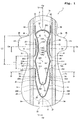
- Fig. 1 is a top plan view showing a sanitary napkin 1 as an absorbent article according to a first embodiment of the present invention, wherein the skin surface faces upward;
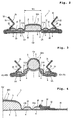
- Fig. 2 is a sectional view taken along line II-II (lateral reference line), showing a state where the sanitary napkin of Fig. 1 is attached to a groin piece of an undergarment;
- Fig. 3 is a sectional view showing a state where the sanitary napkin attached to the groin piece is deformed during wear;
- Fig. 4 is a half sectional view of the sanitary napkin of Fig. 1 taken along line IV-IV;
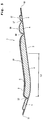
- Fig. 5 is a sectional view of the sanitary napkin of Fig. 1 taken along line V-V (longitudinal centerline).
- the sanitary napkin 1 of Fig. 1 is an elongated sanitary napkin that is suitable for nighttime use by a woman during menstruation, wherein the entire length in the longitudinal direction is from about 200 to 380 mm.
- the sanitary napkin 1 has longitudinally extending right and left side edges 1a and 1b that are laterally spaced an equal distance apart from a longitudinal centerline Oy-Oy and outwardly curved front and rear end edges 1c and 1d that are longitudinally spaced apart from a lateral reference line Ox-Ox.
- the distance from the lateral reference line Ox-Ox to the rear end edge 1d is larger than the distance from the lateral reference line Ox-Ox to the front end edge 1c.
- the right and left side edges 1a and 1b project laterally outwardly, thereby providing wings 1A and 1A.
- the right and left side edges 1a and 1b are curved to gradually rearwardly increase the lateral separation distance therebetween, thereby providing rear flaps 1B and 1B.
- the sanitary napkin 1 comprises a liquid-impermeable backsheet 2 appearing on the garment surface and a liquid-permeable topsheet 3 appearing on the skin surface. Between the backsheet 2 and the topsheet 3, a liquid absorbent layer 4 is interposed. As indicated by a dotted line in Fig. 1, the liquid absorbent layer 4 extends over a large area from a position just inside the front end edge 1c to a position just inside the rear end edge 1d, but for the wings 1A, 1A and the rear flaps 1B, 1B. As will be described later, basis weight and density of the liquid absorbent layer 4 are different for different portions.
- compressed groove 10 is formed in the skin surface by locally pressing and heating at least the topsheet 3 and the liquid absorbent layer 4. More specifically, the compressed groove 10 is formed by embossing with a heating roller in such a manner that after the liquid absorbent layer 4 is stacked on the topsheet 3, a smooth surface roller is applied to a surface of the liquid absorbent layer 4 while a heating roller whose surface has projections arranged in a pattern for embossing is applied to a surface of the topsheet 3 for pressing and heating.
- the compressed groove 10 has high-density compressed portions 10a, in which the liquid absorbent layer 4 and the topsheet 3 are pressed until they get almost filmy, and medium-density compressed portions 10b positioned between adjacent high-density compressed portions 10a, in which although doesn't get filmy, the liquid absorbent layer 4 is of a higher density than in portions other than the compressed groove 10.
- the high-density compressed portions 10a and the medium-density compressed portions 10b alternate with each other in every part of the compressed groove 10 patterned as shown in Fig. 1, providing continuous grooves where the skin surface of the sanitary napkin 1 is recessed toward the side of the backsheet 2.
- the compressed groove 10 has several distinct compressed grooves indicated by numerals 11-17.
- the inner compressed grooves 11 and 11 are disposed symmetrically about the longitudinal centerline Oy-Oy.
- the inner compressed grooves 11 and 11 include front curved portions 11A and 11A, inflected portions 11B and 11B and rear oblique portions 11D and 11D.
- the front curved portions 11A and 11A are curved toward the longitudinal centerline Oy-Oy so that separation distance therebetween is minimum at the lateral reference line Ox-Ox.
- the separation distance between the inner compressed grooves 11 and 11 gradually increases. Then, the separation distance becomes largest at the inflected portions 11B and 11B and gradually decreases rearwardly from the inflected portions 11B and 11B to provide the rear oblique portions 11D and 11D.
- the right and left inner compressed grooves 11 and 11 are connected to each other through a front connecting compressed groove 12.
- the front connecting compressed groove 12 is curved toward the front end edge 1c.
- extension compressed grooves 13 and 13 are further extended toward the front end edge 1c.
- the extension compressed grooves 13 and 13 are disposed symmetrically about the longitudinal centerline Oy-Oy.
- the extension compressed grooves 13 and 13 may extend in parallel with the longitudinal centerline Oy-Oy or extend such that separation distance therebetween gradually increases toward the front end edge 1c.
- the inner compressed grooves 11 and 11 are connected to each other through a rear connecting compressed groove 14.
- the rear connecting compressed groove 14 is curved toward the rear end edge 1d.
- the inner compressed grooves 11 and 11, the front connecting compressed groove 12, the extension compressed grooves 13 and 13 and the rear connecting compressed groove 14 are mutually connected.
- a given area of the skin surface of the sanitary napkin 1 is surrounded by the inner compressed grooves 11 and 11, the front connecting compressed groove 12 and the rear connecting compressed groove 14, and this surrounded area is referred to as central region 20.
- the central region 20 is of an elongated shape symmetrical about the longitudinal centerline Oy-Oy, wherein a portion forward of the lateral reference line Ox-Ox is shorter than a portion rearward of the lateral reference line Ox-Ox.
- front outer compressed grooves 15 and 15 are disposed at positions spaced laterally apart from the front curved portions 11A and 11A of the inner compressed grooves 11 and 11.
- the front outer compressed grooves 15 and 15 are within a range having a given length forwardly and rearwardly from the lateral reference line Ox-Ox.
- the front outer compressed grooves 15 and 15 are curved similarly to the front curved portions 11A and 11A. More specifically, the separation distance between the front curved portion 11A and the front outer compressed groove 15 is uniform over the entire length of the front outer compressed groove 15.
- rear outer compressed grooves 16 and 16 At positions spaced laterally apart from the rear oblique portions 11D and 11D of the inner compressed grooves 11 and 11, on the other hand, there are disposed rear outer compressed grooves 16 and 16.
- the rear outer compressed grooves 16 and 16 includes opposing portions 16A and 16A that are generally parallel with the longitudinal centerline Oy-Oy and oblique portions 16B and 16B that are extended rearwardly continuously from the opposing portions 16A and 16A to gradually decrease separation distance therebetween toward the rear end edge 1d. Furthermore, rear ends of the rear outer compressed grooves 16 and 16 are connected to each other through a rear connecting compressed groove 17.
- the rear outer compressed grooves 16 and 16 and the rear connecting compressed groove 17 thus continuously formed are symmetrical about the longitudinal centerline Oy-Oy.
- the rear connecting compressed groove 17 is curved toward the rear end edge 1d.
- Rear ends 15A and 15A of the front outer compressed grooves 15 and 15 are located forward of the inflected portions 11B and 11B of the inner compressed grooves 11 and 11, whereas front ends 16D and 16D of the rear outer compressed grooves 16 and 16 are located rearward of the inflected portions 11B and 11B. Between the rear ends 15A and 15A and the front ends 16D and 16D, therefore, the front outer compressed grooves 15 and 15 are separated from the rear outer compressed grooves 16 and 16.
- the side regions outside the inner compressed grooves 11 and 11 do not have outer compressed grooves within the range between the rear ends 15A and 15A and the front ends 16D and 16D, so that the rear ends 15A and 15A are longitudinally separated from the front ends 16D and 16D by a separation distance L1.
- the separation distance L1 is about 20 to 60 mm, as set forth above.
- imaginary extensions Lh and Lh which are extended in parallel with the longitudinal centerline Oy-Oy from the front ends 16D and 16D of the rear outer compressed grooves 16 and 16, more specifically, from the front ends 16D and 16D along width centers of the rear outer compressed grooves 16 and 16, intersect the inner compressed grooves 11 and 11.
- the imaginary extensions Lh and Lh intersect the inflected portions 11B and 11B of the inner compressed grooves 11 and 11.
- the imaginary extensions Lh and Lh may intersect the rear oblique portions 11D and 11D of the inner compressed grooves 11 and 11.
- the central region 20 includes a front central region 20A, an intermediate central region 20B, and a rear central region 20D.
- the intermediate central region 20B is within the area of the separation distance L1 between the rear ends 15A and 15A of the front outer compressed grooves 15 and 15 and the front ends 16D and 16D of the rear outer compressed grooves 16 and 16.
- the front central region 20A is within an area extending from a line between the rear ends 15A and 15A to the front connecting compressed groove 12;
- the rear central region 20D is within an area extending from a line between the front ends 16D and 16D to the rear connecting compressed groove 14.
- a position between the inflected portions 11B and 11B, i.e., the portion where the separation distance between the inner compressed grooves 11 and 11 becomes largest is referred to as widened portion.
- Regions of a uniform width between the front curved portions 11A and 11A of the inner compressed grooves 11 and 11 and the front outer compressed grooves 15 and 15 are first front side regions 21 and 21; regions positioned laterally outside the front outer compressed grooves 15 and 15 and having the liquid absorbent layer 4 therein are second front side regions 22 and 22. Regions positioned outside portions of the inner compressed grooves 11 and 11 which define the intermediate central region 20B therebetween are intermediate side regions 23 and 23. The intermediate side regions 23 and 23 are within the area of the separation distance L1.
- Regions between the rear oblique portions 11D and 11D of the inner compressed grooves 11 and 11 and the rear outer compressed grooves 16 and 16 are first rear side regions 24 and 24; regions positioned laterally outside the rear outer compressed grooves 16 and 16 and having the liquid absorbent layer 4 therein are second rear side regions 25 and 25.
- a region positioned rearward of the rear end of the rear connecting compressed groove 14 but inside the rear outer compressed grooves 16 and 16 and the rear connecting compressed groove 17 is first rear region 26.
- a region positioned rearward of the rear end of the rear connecting compressed groove 14 but outside the rear outer compressed grooves 16 and 16 and the rear connecting compressed groove 17 and having the liquid absorbent layer 4 therein is second rear region 27.
- a liquid guide layer 5 is provided between the topsheet 3 and the liquid absorbent layer 4.
- the liquid guide layer 5 is present only within the central region 20, without overlapping with the inner compressed grooves 11 and 11.
- the liquid guide layer 5 and the topsheet 3 are stacked, the compressed groove 10, i.e., the distinct compressed grooves indicated by numerals 11-17 are embossed with a heating roller, and then the backsheet 2 is laid beneath the liquid absorbent layer 4 and bonded thereto through a hot-melt adhesive or the like.
- the backsheet 2 and the topsheet 3 are bonded together through a hot-melt adhesive or by heat-embossing.
- the backsheet 2 and the topsheet 3 are likewise bonded together, and liquid-impermeable sheets 30 and 30 are laid on and bonded to the topsheet 3 and the backsheet 2 through a hot-melt adhesive, as shown in Figs. 1, 2 and 4.
- the wings 1A and 1A and the rear flaps 1B and 1B are mainly composed of the backsheet 2 and the liquid-impermeable sheets 30.
- the liquid-impermeable sheets 30 are folded in two with a plurality of elastically extensible members 32 interposed therebetween, wherein the confronting surfaces of the folded liquid-impermeable sheet 30 are bonded to each other so as to prevent the elastically extensible members 32 from slipping off.
- front fixation regions 33 and 33 the liquid-impermeable sheets 30 thus folded in two are refolded and then bonded and fixed to the skin surface in such a folded state.
- rear fixation regions 34 and 34 the liquid-impermeable sheets 30 are bonded and fixed to the skin surface in such a folded state.
- the front fixation regions 33 and 33 and the rear fixation regions 34 and 34 are indicated by hatching for the convenience of making clear their ranges in the drawing.
- the rear fixation region 34 is also shown in the sectional view of Fig. 4.
- the liquid-impermeable sheets 30 and 30 are free within a given width, providing leakage preventing walls 31 and 31.
- the elastically extensible members 32 exert a longitudinal elastic shrinkage force on the leakage preventing walls 31 and 31.
- Front action ends 35 of the elastic shrinkage force are rear ends of the front fixation regions 33, while rear action ends 36 of the elastic shrinkage force are front ends of the rear fixation regions 34.
- the action ends 35 and the action ends 36 are attracted to each other due to the elastic shrinkage force, so that the sanitary napkin 1 is deformed with its skin surface slightly recessed within an area of a distance L2 between the action ends 35 and the action ends 36, as shown in Fig. 5.
- the leakage preventing walls 31 and 31 are raised from the skin surface within the area between the action ends 35 and the action ends 36, as shown in Fig. 2.
- the front action ends 35 are in the same longitudinal position as the boundaries between the inner compressed grooves 11 and the front connecting compressed grooves 12 or in the vicinity thereof.
- the rear action ends 36 are positioned rearward of the inflected portions 11B of the inner compressed grooves 11 but forward of the front ends 16D of the rear outer compressed grooves 16. Accordingly, the elastic shrinkage force of the elastically extensible members 32 mainly acts on an area including the intermediate central region 20B and the front central region 20A.
- the elastic shrinkage force does not act on a front potion where the extension compressed grooves 13 and 13 are present, the front portion can be certainly kept in a flat state.
- the elastic shrinkage force does not act on a rear portion where the rear outer compressed grooves 16 and 16 and the rear connecting compressed groove 17 are present, the rear portion can be certainly kept in a flat state.
- the topsheet 3 may be a through-air bonded nonwoven fabric having a basis weight of about 25 g/m 2 , wherein sheath/core bicomponent synthetic fibers, of which the core component is polyethylene terephthalate (PET) containing titanium oxide and the sheath component is polyethylene (PE), are bonded together by means of hot air.
- the basis weight of the topsheet 3 may vary from 15 to 60 g/m 2 . If it is below the lower limit, the topsheet 3 may possibly break during use due to lack of sufficient surface strength. If it is above the upper limit, on the other hand, the topsheet 3 may possibly give a stiff feel to the wearer's body and therefore the wearer may feel uncomfortable in the crotch.
- its density is preferably equal to or less than 0.12 g/cm 3 .
- the topsheet 3 may be a spunbonded or spunlaced nonwoven fabric, a synthetic resin film with a large number of liquid passage holes, or a synthetic resin sheet formed in the shape of a net.
- the backsheet 2 is a liquid-impermeable, breathable sheet such as a polyethylene (PE) or polypropylene (PP) film formed with minute pores.
- the minute pores may be appropriately distributed over the film for improving breathability such as by adding inorganic filler such as CaCO 3 and BaSO 4 to the plastic sheet, followed by drawing.
- the film may have a thickness of about 15 to 50 ⁇ m.
- the liquid absorbent layer 4 may be formed by adding synthetic absorbent polymer such as polyacrylate, polyacrylamide and maleic anhydride or natural absorbent polymer such as starch and cellulose to an aggregate of pulp such as ground pulp, mercerized pulp or crosslinked pulp, wherein the pulp and the synthetic absorbent polymer or the like are wrapped in hydrophilic tissue paper.
- synthetic absorbent polymer such as polyacrylate, polyacrylamide and maleic anhydride or natural absorbent polymer such as starch and cellulose
- pulp such as ground pulp, mercerized pulp or crosslinked pulp, wherein the pulp and the synthetic absorbent polymer or the like are wrapped in hydrophilic tissue paper.
- the liquid guide layer 5 may be a through-air bonded nonwoven fabric comprising eccentric sheath/core bicomponent synthetic fibers, of which the core component is polypropylene (PP) and the sheath component is polyethylene (PE), and having a density of 0.005 to 0.025 g/cm 3 .
- the through-air bonded nonwoven fabric is prepared to have a basis weight of 20 g/m 2 and then used for the liquid guide layer 5 in three-ply construction.
- the liquid guide layer 5 may be an air-laid nonwoven fabric, in which hydrophilic fibers such as pulp and rayon are accumulated in air, bonded together with a binder, and pressed with a heating roller, wherein the hydrophilic fibers may be optionally mixed with synthetic fibers. It is also possible to stack both the air-laid nonwoven fabric and the through-air bonded nonwoven fabric on the liquid absorbent layer 4 and cover them with the topsheet 3.
- the liquid-impermeable sheet 30 for forming the leakage preventing wall 31 is a spunbonded nonwoven fabric, a meltblown nonwoven fabric or a lamination thereof, and is preferably treated to be water-repellent.
- the backsheet 2 has pressure-sensitive adhesive layers (not shown) on its exterior surface (i.e., garment surface).
- the pressure-sensitive adhesive layers are provided on a central portion of the sanitary napkin 1, as well as on the wings 1A, 1A and the rear flaps 1B, 1B.
- Fig. 6 is a view for describing properties of respective portions of the sanitary napkin 1.
- the drawing used for Fig. 6 is similar to that used for Fig. 1, but reference numerals are omitted except for portions necessary for description of the properties.
- the basis weight of the liquid absorbent layer 4 becomes highest at the central region 20, so that the basis weight of the liquid absorbent layer 4 is lower at the first front side regions 21, 21, the first rear side regions 24, 24 and the first rear region 26 than at the central region 20.
- the basis weight of the liquid absorbent layer 4 at the remaining regions, i.e., at the region forward of the front connecting compressed groove 12, the second front side regions 22, 22, the intermediate side regions 23, 23, the second rear side regions 25, 25 and the second rear region 27 may be equal to, slightly higher than, or lower than that at the first front side regions 21, 21 and so on.
- the basis weight of the liquid absorbent layer 4 at the central region 20 is preferably in the range of 400 to 1200 g/m 2 , more preferably in the range of 500 to 1000 g/m 2 .
- the basis weight of the liquid absorbent layer 4 at the first front side regions 21, 21, the first rear side regions 24, 24 and the first rear region 26 is preferably in the range of 300 to 900 g/m 2 , more preferably in the range of 350 to 600 g/m 2 .
- the basis weight of the liquid absorbent layer 4 at the region forward of the front connecting compressed groove 12, the second front side regions 22, 22, the intermediate side regions 23, 23, the second rear side regions 25, 25 and the second rear region 27 is preferably in the range of 300 to 500 g/m 2 , but the upper limit may be 700 g/m 2 , if required.
- the compressed grooves 11-17 shown in Fig. 6 are formed at a time by heat-embossing with the heating roller.
- the topsheet 3 is pressed together with the liquid absorbent layer 4 at the front curved portions 11A, 11A and the front outer compressed grooves 15, 15, the density of the liquid absorbent layer 4 increases at the first front side regions 21, 21 due to tension given to portions of the topsheet 3 covering the first front side regions 21, 21.
- the liquid absorbent layer 4 can be pressed with the shallow grooves at the first front side regions 21, 21 as the front curved portions 11A, 11A and the front outer compressed grooves 15, 15 are formed by pressing. In this case, therefore, the density of the liquid absorbent layer 4 can be increased more at the first front side regions 21, 21. Likewise, the density of the liquid absorbent layer 4 can be increased more at the first rear side regions 24, 24 between the rear oblique portions 11D, 11D and the rear outer compressed grooves 16, 16.
- the density of the liquid absorbent layer 4 becomes highest at the first front side regions 21, 21.
- the density at the first rear side regions 24, 24 is preferably equal to that at the first front side regions 21, 21, but may be slightly lower than that at the first front side regions 21, 21.
- the density of the liquid absorbent layer 4 at the first rear region 26 is slightly lower than that at the first front side regions 21, 21 and the first rear side regions 24, 24.
- the density at the central region 20 is slightly lower than that at the first rear region 26, but may be equal to that at the first rear region 26.
- the density of the liquid absorbent layer 4 at the region forward of the front connecting compressed groove 12, the second front side regions 22, 22, the intermediate side regions 23, 23, the second rear side regions 25, 25 and the second rear region 27 is lower than that at the other regions.
- the density of the liquid absorbent layer 4 at the first front side regions 21, 21 and the first rear side regions 24, 24 is preferably in the range of 0.08 to 0.2 g/cm 3 .
- the density of the liquid absorbent layer 4 at the central region 20 is preferably in the range of 0.05 to 0.18 g/cm 3 .
- the density of the liquid absorbent layer 4 at the second front side regions 22, 22, the intermediate side regions 23, 23 and the second rear side regions 25, 25 is preferably in the range of 0.05 to 0.13 g/cm 3 .
- the density of the liquid absorbent layer 4 at the first front side regions 21, 21 is preferably higher than that at the central region 20 and that at the second front side regions 22, 22 and the intermediate side regions 23, 23 by at least 0.01 g/cm 3 , more preferably, by at least 0.02 g/cm 3 .
- the density of the liquid absorbent layer 4 at the first rear side regions 24, 24 is preferably higher than that at the central region 20 and that at the second rear side regions 25, 25 and the intermediate side regions 23, 23 by at least 0.01 g/cm 3 , more preferably, by at least 0.02 g/cm 3 .
- both the density of the high-density compressed portions 10a and the density of the medium-density compressed portions 10b fall within the range of 0.5 to 1.5 g/cm 3 .
- Fig. 6 shows sections of different bending stiffnesses in the sanitary napkin 1.
- second section (ii) An area traversed by the rear oblique portion 11D of the inner compressed groove 11, the first rear side region 24 and the rear outer compressed groove 16 and overlapping with the central region 20 and the second rear side region 25 is referred to as second section (ii).
- third section (iii) An area containing the inflected portion 11B of the inner compressed groove 11 and overlapping with the central region 20 and the intermediate side region 23 (but not overlapping with the front outer compressed groove 15 and the rear outer compressed groove 16) is referred to as third section (iii).
- fourth section (iv) An area located in the intermediate central region 20B but not overlapping with any compressed groove is referred to as fourth section (iv).
- the longitudinal bending stiffness means stiffness measured by bending the each respective section in the longitudinal direction of the sanitary napkin 1, wherein none of the components constituting sanitary napkin 1 is removed from the sections.
- the bending stiffness becomes highest at the first section (i), and the second section (ii) is similar in bending stiffness to the first section (i).
- the bending stiffness is sufficiently lower in the third section (iii) than in the first section (i) and in the second section (ii). Furthermore, the bending stiffness is much lower in the fourth section (iv) than in the third section (iii).
- the bending stiffness can be measured using a Gurley Bending Resistance Tester, wherein it is preferred that the first section (i) and the second section (ii) have a Gurley stiffness of 20 to 35 mN, the third section (iii) has a Gurley stiffness of 8 to 18 mN, and the fourth section (iv) has a Gurley stiffness of 3 to 8 mN.
- the Gurley stiffness is preferably from 3 to 38 mN at ever part of the sanitary napkin. If it is equal to or greater than 3 mN, the sanitary napkin can stabilize in shape; if it is equal to or less than 38 mN, the sanitary napkin can be prevented from being excessively stiff and giving a stiff feel to the wearer's body.
- the measurements of the Gurley stiffness are made on the each respective section having a width of 25 mm in the lateral direction (i.e., in a direction parallel with the lateral reference line Ox-Ox) and a length of 38 mm in the longitudinal direction, using a Gurley Flexibility Tester manufactured by YASUDA SEIKI SEISAKUSHO, LTD.
- the measurements of the Gurley stiffness are made in such a manner that after the sections (i) to (iv) are cut out of the sanitary napkin 1 to have a width of 25 mm in the lateral direction and a length of 38 mm in the longitudinal direction, bending test is performed with each sample brought into contact with a pendulum of the Gurley Flexibility Tester within a length of 6.3 mm from one end edge on the side of the rear end edge 1d while being held by a chuck within a length of 6.3 mm from the other end edge on the side of the front end edge 1c, wherein the average of the value measured for one bending direction in which the skin surface is pushed and the value measured for the other bending direction in which the garment surface is pushed is taken as the Gurley stiffness.
- the length of the central region 20, i.e., the longitudinal distance between the front connecting compressed groove 12 and the rear connecting compressed groove 14 is about 120 to 300 mm.
- the width of the central region 20 on the lateral reference line Ox-Ox, i.e., the minimum width W1 of the front central region 20A shown in Fig. 2 is decided according to the width of the woman's genital organ. Because the crotch width of average women is about 30 mm, the width W1 is preferably in the range of 15 to 50 mm, more preferably in the range of 20 to 40 mm.
- the lateral distance between the inflected portions 11B, 11B of the inner compressed grooves 11, 11, i.e., the width of the widened portion of the intermediate central region 20B is larger than the width W1 by about 10 to 40 mm.
- the length of the front outer compressed grooves 15, 15 and the length of the first front side regions 21, 21 are both in the range of 30 to 120 mm.
- the width of the first front side regions 21, 21 is preferably in the range of 5 to 15 mm, more preferably in the range of 5 to 10 mm.
- the minimum distance between the rear oblique portions 11D, 11D of the inner compressed grooves 11, 11 and the rear outer compressed grooves 16, 16 is also in the range of 5 to 15 mm.
- the respective compressed grooves 11-17 have a width of about 0.5 to 3 mm.
- Fig. 2 is a sectional view showing a state where the sanitary napkin 1 is attached to an inner side of a groin piece 41 of an undergarment
- Fig. 7 is a top plan view showing the sanitary napkin 1 attached to the groin piece 41 from inside of the undergarment.
- the pressure-sensitive adhesive layers provided on the exterior surface of the backsheet 2 is adhered to the inner side of the groin piece 41, and at this time, the rear flaps 1B, 1B are also adhered to the inner side of the groin piece 41.
- the wings 1A, 1A are folded back against an outer side of the undergarment to cover both side edges of the groin piece 41, and adhered to the outer side of the groin piece 41 through the pressure-sensitive adhesive layers provided on the garment surface of the wings 1A, 1A.
- the thighs exert a compressive force F1, F1 toward the longitudinal centerline Oy-Oy on the front outer compressed grooves 15, 15, as shown in Fig. 7.
- the compressive force F1, F1 is transmitted to the first front side regions 21, 21 of a high density and a high stiffness via the front outer compressed grooves 15, 15, and further to the front curved portions 11A, 11A of the inner compressed grooves 11, 11.
- the front outer compressed grooves 15, 15 and the front curved portions 11A, 11A are located sufficiently below the midpoint of the thickness of the front central region 20A, and the first front side regions 21, 21 are also located sufficiently below the midpoint. Accordingly, when the compressive force F1, F1 is exerted, the front outer compressed grooves 15, 15, the first front side regions 21, 21 and the front curved portions 11A, 11A try to get under the front central region 20A, so that the front central region 20A is supported from below and raised up toward the wearer's body by the first front side regions 21, 21 of a high stiffness. Such deformation can bring the front central region 20A into close contact with the vaginal opening.
- a compressive force F2, F2 toward the longitudinal centerline Oy-Oy acts on the opposing portions 16A, 16A of the rear outer compressed grooves 16, 16.
- the compressive force F2, F2 is also exerted mainly by the approach of the thighs.
- the third section (iii) shown in Fig. 6 has a lower stiffness than portions positioned forward and rearward thereof. Forward of the third section (iii) of a lower stiffness, as shown in Fig. 7, the rear ends 15A, 15A of the front outer compressed grooves 15, 15 (i.e., rear ends of the first sections (i) of a higher stiffness) subjected to the compressive force F1, F1 exert a compressive force F3, F3 toward the longitudinal centerline Oy-Oy.
- the compressive force F3, F3 has force components perpendicular to the portions of the inner compressed grooves 11, 11.
- the front ends 16D, 16D of the rear outer compressed grooves 16, 16 i.e., front ends of the second sections (ii) of a higher stiffness
- F2 exert a compressive force F4, F4 toward the longitudinal centerline Oy-Oy
- the compressive force F4, F4 also has force components perpendicular to the rear oblique portions 11D, 11D of the inner compressed grooves 11, 11.
- the intermediate central region 20B has the widened portion between the inflected portions 11B and 11B, and the compressive forces F3, F3 and F4, F4 act on the front and rear portions of the widened portion from four directions.
- the compressive forces F3, F3 and F4, F4 have force components that concentrate near the center of the intermediate central region 20B, and additionally, the action points of the respective compressive forces are located sufficiently below the midpoint of the thickness of the intermediate central region 20B (i.e., located closer to the backsheet 2).
- the fourth section (iv) within the intermediate central region 20B and the third sections (iii) at both sides thereof are of a relatively low stiffness, when the compressive forces are exerted from four directions to concentrate at a lower position, the inner compressed grooves 11, 11 serve as flexible hinges so that the intermediate central region 20B is raised up toward the wearer's body as if it were picked up from four directions with the inflected portions 11B and 11B positioned therebetween.
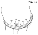
- the sanitary napkin 1 is longitudinally curved with its garment surface so bulged as to conform to the contour of the wearer's body, as shown in Fig. 10. Since the skin surface of the sanitary napkin 1 is compressed at this time, the front ends 16D, 16D of the rear outer compressed grooves 16, 16 tend to approach the rear ends 15A, 15A of the front outer compressed grooves 15, 15. That is, the second sections (ii) that are highly stiff and located rearward of the intermediate central region 20B tend to approach the first sections (i) that are located forward thereof but also highly stiff.
- a compressive force F5, F5 is exerted on the intermediate central region 20B from behind as shown in Fig. 7, and the compressive force F5, F5 is supported by the first sections (i). Since the compressive force F5, F5 acts on both sides of the intermediate central region 20B, deformation occurs such that the intermediate central region 20B is folded to project toward the wearer's body, wherein its ridge is shaped to extend along the longitudinal centerline Oy-Oy and pressed against the wearer's body.
- the action ends 35 and 36 of the elastically extensible members 32 which exert an elastic shrinkage force on the leakage preventing walls 31, 31 are located at longitudinally opposite sides with the intermediate central region 20B positioned therebetween. Therefore, the elastic shrinkage force of the elastically extensible members 32 also functions to add to the compressive force F5, F5.
- the volume is larger in the intermediate central region 20B than in the front and rear regions of the central region 20.
- the bulging amount of the intermediate central region 20B toward the wearer's body is increased, so that the surface of the intermediate central region 20B can project more toward the wearer's body than the front central region 20A.
- Fig. 10 is a sectional view showing the outline of the woman's crotch to which the sanitary napkin 1 is applied.
- the vaginal opening (N) is located posterior to the mons pubis (M), and the vaginal opening (N) is deeply recessed at a position between the labia majora.
- the crotch is outwardly bulged from the vaginal opening (N) to the perineum (O) and then shallowly recessed near the anus (P).
- the cleft (Q) of the buttocks extends continuously rearwardly therefrom.
- the front central region 20A deformed into the state of Fig. 3 enters the recess between the labia majora to fit on the vaginal opening (N).
- the intermediate central region 20B can fit on the perineum (O) and into the groove of the labia majora anterior to it, as well as into the recess near the anus posterior to the perineum (O).
- the rear central region 20D can fit into the recess near the anus (P) and the cleft (Q) posterior to it, wherein since the width of the rear central region 20D gradually decreases toward the rear end edge 1d, the rear central region 20D easily enters the cleft (Q) of the buttocks and hardly gives an uncomfortable feel to the wearer's body after the entry.
- Menstrual blood discharged from the vaginal opening (N) is given to the front central region 20A and absorbed.
- Menstrual blood trying to flow rearwardly along the wearer's crotch or the topsheet 3 of the sanitary napkin 1 in a lying posture or the like is blocked by contact between the intermediate central region 20B and the perineum (O), and menstrual blood thus blocked is mainly absorbed by the liquid absorbent layer 4 in the intermediate central region 20B.
- the menstrual blood can be prevented from migrating from the anus (P) to the cleft (Q), so that the rearward leakage of menstrual blood can be effectively prevented.
- the elastic shrinkage force of the elastically extensible members 32 provided in the leakage preventing walls 31 acts between the action ends 35 and the action ends 36, as shown in Fig. 1, whereas the elastic shrinkage force does not act on the portion forward of the action ends 35 and the portion rearward of the action ends 36. Therefore, since the portion forward of the front connecting compressed groove 12 can be kept flat while being allowed to be folded at the extension compressed grooves 13, 13, this portion can easily fit on the mons pubis (M). Likewise, the portion rearward of the action ends 36 can also be kept flat so as to cover a large area of the buttocks.
- the intermediate central region 20B and the intermediate side regions 23, 23 are of a low stiffness, the portion positioned forward of them and intended to fit in the wearer's crotch is of a high stiffness due to the presence of the first sections (i), and the portion positioned rearward of the intermediate side regions 23, 23 and intended to cover the wearer's buttocks is of a high stiffness due to the presence of the second sections (ii).
- the intermediate central region 20B and the intermediate side regions 23, 23 can function as deformable boundaries, so that the front portion fitting in the wearer's crotch and the rear portion covering the wearer's buttocks can move independently from each other.
- the displacement in position can be absorbed by deformation of the intermediate central region 20B and the intermediate side regions 23, 23.
- the sanitary napkin 1 can be certainly prevented from twisting or deforming as a whole.
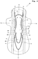
- Fig. 8 is a top plan view showing a sanitary napkin 100 according to a second embodiment of the present invention.
- the rear outer compressed grooves 16 are different in shape from those shown in Fig. 1, but the other constructions and shapes are identical to those of the embodiment shown in Fig. 1.
- front end-abutting portions 16E, 16E are disposed at the front ends of the rear outer compressed grooves 16, 16 to extend substantially parallel with the rear oblique portions 11D, 11D of the inner compressed grooves 11, 11.
- the front end-abutting portions 16E, 16E get under the rear oblique portions 11D, 11D of the inner compressed grooves 11, 11 to raise the rear portion of the intermediate central region 20B high toward the wearer's body, wherein the raised intermediate central region 20B is supported from the side of the backsheet 2 by the front end-abutting portions 16E, 16E.
- Fig. 9 is a top plan view showing a sanitary napkin 200 according to a third embodiment of the present invention.
- short compressed grooves 19, 19 are disposed between the inflected portions 11B, 11B, i.e., in the rear portion of the intermediate central region 20B.
- This embodiment has the same basic shape and construction as the first embodiment of Fig. 1, except for the short compressed grooves 19, 19. Therefore, the detailed description of the portions having the same shape and construction as those of the first embodiment of Fig. 1 will be omitted by designating them by the common reference numerals.
- the high-density compressed portions 10a and the medium-density compressed portions 10b alternate with each other and the liquid absorbent layer 4 is compressed together with the topsheet 3, as in the other compressed grooves 11-17.
- the short compressed grooves 19, 19 are disposed symmetrically about the longitudinal centerline Oy-Oy, wherein the separation distance between the short compressed grooves 19, 19 gradually rearwardly decreases, as in the rear oblique portions 11D, 11D. It should be noted that the short compressed grooves 19, 19 are located within the range L1 between the rear ends 15A of the front outer compressed grooves 15 and the front ends 16D of the rear outer compressed grooves 16.
- the intermediate central region 20B receives the compressive forces F3, F3 and F4, F4 from four directions at the front and rear portions of the inflected portions 11B, 11B and further receives the longitudinal compressive force F5, F5 from the rear outer compressed grooves 16, 16.
- the intermediate central region 20B receiving the compressive forces from the respective directions can be inhibited from being widened laterally, and in addition, since the short compressed grooves 19, 19 can function as longitudinally extending flexible hinges, the intermediate central region 20B can easily be bulged to have a longitudinally extending ridge. As a result, the intermediate central region 20B can certainly fit on the perineum and portions anterior and posterior to it.
- the right and left inner compressed grooves 11 and 11 and the right and left rear outer compressed grooves 16 and 16 may be independent each other without providing the front connecting compressed groove 12, the rear connecting compressed groove 14 and the rear connecting compressed groove 17.
- the topsheet 3 may be apertured to have a large number of liquid passage holes or corrugated to have ribs and grooves alternating with each other.
- a bulky cushion layer such as through-air bonded nonwoven fabric may be disposed between the topsheet 3 and the liquid absorbent layer 4, in addition to the liquid guide layer 5. This will result in further improvement in contact between the intermediate central region 20B and the perineum.
- the topsheet 3 is corrugated to have longitudinally extending ribs and grooves at least partially in each of the intermediate central region 20B, the front central region 20A and the rear central region 20D, furthermore, the topsheet 3 can be laterally stretched when one of these regions is deformed to bulge toward the wearer's body so as not to provide a resistance to the deformation, and as a result, the deformation toward the wearer's body can be made large.
- the intermediate central region 20B can be raised up toward the wearer's body during wear. If the above-mentioned conditions are satisfied, the front outer compressed grooves 11, 11 and the rear outer compressed grooves 16, 16 may be omitted.
- the stiffness may be increased in both the sections (i) and (ii) by increasing the density of the liquid absorbent layer 4 at positions outside the inner compressed grooves 11, 11 or members such as foamed material and paper for reinforcing the stiffness may be provided at positions outside the inner compressed grooves 11, 11.
- the intermediate central region can be certainly raised up toward the wearer's body to come into close contact with the perineum and so on, migration of menstrual blood rearwardly from the front central region can be blocked to effectively prevent rearward liquid leakage.
- the absorbent article can easily follow the movement of the wearer's body while sleeping, it is hardly twisted or wrinkled.
Landscapes
- Health & Medical Sciences (AREA)
- Epidemiology (AREA)
- Engineering & Computer Science (AREA)
- Biomedical Technology (AREA)
- Heart & Thoracic Surgery (AREA)
- Vascular Medicine (AREA)
- Life Sciences & Earth Sciences (AREA)
- Animal Behavior & Ethology (AREA)
- General Health & Medical Sciences (AREA)
- Public Health (AREA)
- Veterinary Medicine (AREA)
- Physics & Mathematics (AREA)
- Fluid Mechanics (AREA)
- Absorbent Articles And Supports Therefor (AREA)
- Orthopedics, Nursing, And Contraception (AREA)
Abstract
Description
in a region where the liquid absorbent layer is present, compressed grooves where the skin surface is recessed toward the garment surface are disposed to extend symmetrically about a longitudinal centerline of the absorbent article, defining a central region between the compressed grooves and side regions laterally outside the central region and adjacent the compressed grooves, the central region including a front central region at a front side in a longitudinal direction of the absorbent article, a rear central region at a rear side in the longitudinal direction, and an intermediate central region between the front and rear central regions, wherein
separation distance between the compressed grooves gradually increases from the front central region to the intermediate central region and also from the rear central region to the intermediate central region so that the intermediate central region has a widened portion in which the separation distance is larger than in regions positioned forward and rearward thereof, wherein
stiffness of the side regions is lower in portions laterally outside the intermediate central region than in portions laterally outside the front and rear central regions.
in a region where the liquid absorbent layer is present, inner compressed grooves where the skin surface is recessed toward the garment surface are disposed to extend symmetrically about a longitudinal centerline of the absorbent article, defining a central region between the inner compressed grooves, the central region including a front central region at a front side in a longitudinal direction of the absorbent article, a rear central region at a rear side in the longitudinal direction, and an intermediate central region between the front and rear central regions, wherein
separation distance between the inner compressed grooves gradually increases from the front central region to the intermediate central region and also from the rear central region to the intermediate central region so that the intermediate central region has a widened portion in which the separation distance is larger than in regions positioned forward and rearward thereof, wherein
front and rear outer compressed grooves separate from the inner compressed grooves are disposed in portions laterally outside the front and rear central regions, respectively, to extend symmetrically about the longitudinal centerline, rear ends of the front outer compressed grooves being spaced longitudinally apart from front ends of the rear outer compressed grooves in portions laterally outside the intermediate central region.
Claims (9)
- An elongated absorbent article comprising a liquid absorbent layer (4), the absorbent article having a skin surface and a garment surface, wherein
in a region where the liquid absorbent layer (4) is present, compressed grooves (11) where the skin surface is recessed toward the garment surface are disposed to extend symmetrically about a longitudinal centerline (Oy-Oy) of the absorbent article, defining a central region (20) between the compressed grooves (11) and side regions laterally outside the central region (20) and adjacent the compressed grooves (11), the central region (20) including a front central region (20A) at a front side in a longitudinal direction of the absorbent article, a rear central region (20D) at a rear side in the longitudinal direction, and an intermediate central region (20B) between the front and rear central regions (20A, 20D), wherein
separation distance between the compressed grooves (11) gradually increases from the front central region (20A) to the intermediate central region (20B) and also from the rear central region (20D) to the intermediate central region (20B) so that the intermediate central region (20B) has a widened portion in which the separation distance is larger than in regions positioned forward and rearward thereof, wherein
stiffness of the side regions is lower in portions laterally outside the intermediate central region (20B) than in portions laterally outside the front and rear central regions (20A, 20D). - An elongated absorbent article as set forth in claim 1, wherein the front central region (20A), the rear central region (20D) and the intermediate central region (20B) are intended to face a vaginal opening, an anus and a perineum of a wearer, respectively.
- An elongated absorbent article as set forth in claim 1, wherein when measured for areas (i, ii, iii) each traversed by one compressed groove (11) to overlap with one of the front, intermediate and rear central regions (20A, 20B, 20D) and one side region adjacent thereto, longitudinal bending stiffness is lower in the area (iii) overlapping with the intermediate central region (20B) than in the area (i) overlapping with the front central region (20A) and in the area (ii) overlapping with the rear central region (20D).
- An elongated absorbent article as set forth in claim 1, wherein density of the liquid absorbent layer (4) in the side regions is lower in the portions laterally outside the intermediate central region (20B) than in the portions laterally outside the front and rear central regions (20A, 20D).
- An elongated absorbent article comprising a liquid absorbent layer (4), the absorbent article having a skin surface and a garment surface, wherein
in a region where the liquid absorbent layer (4) is present, inner compressed grooves (11) where the skin surface is recessed toward the garment surface are disposed to extend symmetrically about a longitudin al centerline (Oy-Oy) of the absorbent article, defining a central region (20) between the inner compressed grooves (11), the central region (20) including a front central region (20A) at a front side in a longitudinal direction of the absorbent article, a rear central region (20D) at a rear side in the longitudinal direction, and an intermediate central region (20B) between the front and rear central regions (20A, 20D), wherein
separation distance between the inner compressed grooves (11) gradually increases from the front central region (20A) to the intermediate central region (20B) and also from the rear central region (20D) to the intermediate central region (20B) so that the intermediate central region (20B) has a widened portion in which the separation distance is larger than in regions positioned forward and rearward thereof, wherein
front and rear outer compressed grooves (15, 16) separate from the inner compressed grooves (11) are disposed in portions laterally outside the front and rear central regions (20A, 20D), respectively, to extend symmetrically about the longitudinal centerline (Oy-Oy), rear ends (15A) of the front outer compressed grooves (15) being spaced longitudinally apart from front ends (16D) of the rear outer compressed grooves (16) in portions laterally outside the intermediate central region (20B). - An elongated absorbent article as set forth in claim 5, wherein imaginary extensions (Lh), which are extended from the front ends (16D) of the rear outer compressed grooves (16) in parallel with the longitudinal centerline (Oy-Oy), intersect portions of the inner compressed grooves (11) which define the intermediate central region (20B) therebetween.
- An elongated absorbent article as set forth in claim 5, wherein the front central region (20A), the rear central region (20D) and the intermediate central region (20B) are intended to face a vaginal opening, an anus and a perineum of a wearer, respectively.
- An elongated absorbent article as set forth in claim 5, wherein density of the liquid absorbent layer (4) is higher in portions (21) between the inner compressed grooves (11) and the front outer compressed grooves (15) and in portions (24) between the inner compressed grooves (11) and the rear outer compressed grooves (16) than in portions (23) laterally outside portions of the inner compressed grooves (11) which define the intermediate central region (20B) therebetween.
- An elongated absorbent article as set forth in claim 1 or 5, wherein elastic members (32) are disposed symmetrically about the longitudinal centerline (Oy-Oy) to exert an elastic shrinkage force in the longitudinal direction so that action ends (35) positioned forward of the intermediate central region (20B) and action ends (36) positioned rearward of the intermediate central region (20B) are attracted to each other.
Applications Claiming Priority (3)
| Application Number | Priority Date | Filing Date | Title |
|---|---|---|---|
| JP2002354174A JP4323786B2 (en) | 2002-12-05 | 2002-12-05 | Absorbent article with vertically long compressed groove |
| JP2002354174 | 2002-12-05 | ||
| PCT/JP2003/015390 WO2004049996A1 (en) | 2002-12-05 | 2003-12-02 | Elongated absorbent article having compression grooves |
Publications (2)
| Publication Number | Publication Date |
|---|---|
| EP1568340A1 true EP1568340A1 (en) | 2005-08-31 |
| EP1568340A4 EP1568340A4 (en) | 2009-05-20 |
Family
ID=32463329
Family Applications (1)
| Application Number | Title | Priority Date | Filing Date |
|---|---|---|---|
| EP03776016A Withdrawn EP1568340A4 (en) | 2002-12-05 | 2003-12-02 | Elongated absorbent article having compression grooves |
Country Status (9)
| Country | Link |
|---|---|
| US (1) | US7312372B2 (en) |
| EP (1) | EP1568340A4 (en) |
| JP (1) | JP4323786B2 (en) |
| KR (1) | KR101070348B1 (en) |
| CN (1) | CN100360101C (en) |
| AU (1) | AU2003284531A1 (en) |
| MY (1) | MY142262A (en) |
| TW (1) | TWI235054B (en) |
| WO (1) | WO2004049996A1 (en) |
Cited By (5)
| Publication number | Priority date | Publication date | Assignee | Title |
|---|---|---|---|---|
| WO2006130646A1 (en) * | 2005-06-02 | 2006-12-07 | The Procter & Gamble Company | Absorbent article having traverse reinforcing element |
| EP2087866A4 (en) * | 2006-11-22 | 2011-12-28 | Uni Charm Corp | Absorptive article and method of producing the same |
| EP2277483A4 (en) * | 2008-05-15 | 2012-05-02 | Unicharm Corp | Absorbent article |
| EP2901979A4 (en) * | 2012-09-28 | 2016-03-30 | Unicharm Corp | Absorbent article |
| US10864120B2 (en) | 2014-02-21 | 2020-12-15 | Attends Healthcare Products, Inc. | Absorbent article with fluid control features |
Families Citing this family (81)
| Publication number | Priority date | Publication date | Assignee | Title |
|---|---|---|---|---|
| JP4180865B2 (en) * | 2002-09-09 | 2008-11-12 | ユニ・チャーム株式会社 | Absorbent article with flexible shaft |
| US7550646B2 (en) * | 2002-09-09 | 2009-06-23 | Uni-Charm Corporation | Absorbent article with resilient portion and method for manufacturing the same |
| EP1982678B1 (en) | 2003-02-12 | 2019-03-27 | The Procter and Gamble Company | Comfortable diaper |
| ATE455528T1 (en) | 2003-02-12 | 2010-02-15 | Procter & Gamble | ABSORBENT CORE FOR AN ABSORBENT ARTICLE |
| JP4476563B2 (en) * | 2003-05-29 | 2010-06-09 | ユニ・チャーム株式会社 | Sanitary napkin |
| JP4540104B2 (en) * | 2004-11-30 | 2010-09-08 | 大王製紙株式会社 | Absorbent articles |
| US9925094B2 (en) | 2004-11-30 | 2018-03-27 | The Procter & Gamble Company | Absorbent article having outwardly convex longitudinal central channels for improved protection |
| CN101065085B (en) * | 2004-11-30 | 2011-03-16 | 宝洁公司 | Absorbent article having a pair of rear side flaps |
| JP4805274B2 (en) * | 2004-11-30 | 2011-11-02 | ザ プロクター アンド ギャンブル カンパニー | Absorbent article including a pair of rear side flaps |
| JP5046488B2 (en) * | 2005-02-24 | 2012-10-10 | 花王株式会社 | Absorbent articles |
| JP4771756B2 (en) | 2005-06-17 | 2011-09-14 | ユニ・チャーム株式会社 | Absorbent articles |
| EP1901692B1 (en) * | 2005-07-13 | 2014-08-27 | SCA Hygiene Products AB | Absorbent article having improved fit |
| JP4913381B2 (en) | 2005-09-26 | 2012-04-11 | ユニ・チャーム株式会社 | Absorbent articles |
| JP4619253B2 (en) * | 2005-09-29 | 2011-01-26 | 花王株式会社 | Absorbent articles |
| JP4808009B2 (en) * | 2005-11-18 | 2011-11-02 | ユニ・チャーム株式会社 | Absorbent articles |
| US20080281287A1 (en) * | 2007-05-08 | 2008-11-13 | Marcelo Ana Maria Elena R | Sanitary napkin including body-facing protrusions for preventing side leakage and obliquely arranged embossed channels |
| GB2454301B (en) | 2007-06-18 | 2012-03-28 | Procter & Gamble | Disposable absorbent article with sealed absorbent core with substantially continuously distributed absorbent particulate polymer material |
| WO2008155699A1 (en) | 2007-06-18 | 2008-12-24 | The Procter & Gamble Company | Disposable absorbent article with substantially continuously distributed absorbent particulate polymer material and method |
| EP2255762A1 (en) | 2008-02-29 | 2010-12-01 | Unicharm Corporation | Absorptive article |
| CA2722538C (en) | 2008-04-29 | 2014-08-12 | The Procter & Gamble Company | Process for making an absorbent core with strain resistant core cover |
| JP5261212B2 (en) * | 2009-01-26 | 2013-08-14 | ユニ・チャーム株式会社 | Absorbent article manufacturing apparatus, absorbent article manufacturing method, and absorbent article |
| CA2678090C (en) | 2009-09-29 | 2011-05-10 | The Procter & Gamble Company | Absorbent products having improved packaging efficiency |
| EP2329803B1 (en) | 2009-12-02 | 2019-06-19 | The Procter & Gamble Company | Apparatus and method for transferring particulate material |
| JP5543847B2 (en) * | 2010-05-31 | 2014-07-09 | ユニ・チャーム株式会社 | Absorbent articles |
| TW201244682A (en) * | 2011-05-12 | 2012-11-16 | Ya-Jing Yang | Mop fabric structure capable of stably releasing water |
| RU2568565C2 (en) | 2011-06-10 | 2015-11-20 | Дзе Проктер Энд Гэмбл Компани | Disposable diapers |
| EP2717822B1 (en) | 2011-06-10 | 2019-06-05 | The Procter and Gamble Company | Absorbent core for disposable absorbent articles |
| CA2838432C (en) | 2011-06-10 | 2018-02-27 | The Procter & Gamble Company | Absorbent structure for absorbent articles |
| EP2532329B1 (en) | 2011-06-10 | 2018-09-19 | The Procter and Gamble Company | Method and apparatus for making absorbent structures with absorbent material |
| EP2532328B1 (en) | 2011-06-10 | 2014-02-26 | The Procter and Gamble Company | Method and apparatus for making absorbent structures with absorbent material |
| PL2532332T5 (en) | 2011-06-10 | 2018-07-31 | The Procter And Gamble Company | Disposable diapers with a reduced connection between the absorbent body and the underlayer |
| PL3287110T3 (en) | 2011-06-10 | 2019-08-30 | The Procter And Gamble Company | Method of making absorbent structures for absorbent articles |
| JP6030876B2 (en) * | 2012-07-19 | 2016-11-24 | ユニ・チャーム株式会社 | Absorbent articles |
| EP2919737B1 (en) | 2012-11-13 | 2018-12-26 | The Procter and Gamble Company | Absorbent articles with channels and signals |
| EP2740452B1 (en) | 2012-12-10 | 2021-11-10 | The Procter & Gamble Company | Absorbent article with high absorbent material content |
| EP2740449B1 (en) | 2012-12-10 | 2019-01-23 | The Procter & Gamble Company | Absorbent article with high absorbent material content |
| US9216118B2 (en) | 2012-12-10 | 2015-12-22 | The Procter & Gamble Company | Absorbent articles with channels and/or pockets |
| US10639215B2 (en) | 2012-12-10 | 2020-05-05 | The Procter & Gamble Company | Absorbent articles with channels and/or pockets |
| US9216116B2 (en) | 2012-12-10 | 2015-12-22 | The Procter & Gamble Company | Absorbent articles with channels |
| EP2740450B1 (en) | 2012-12-10 | 2025-12-31 | The Procter & Gamble Company | Absorbent item with a high proportion of superabsorbent material |
| US8979815B2 (en) | 2012-12-10 | 2015-03-17 | The Procter & Gamble Company | Absorbent articles with channels |
| US9931253B2 (en) * | 2012-12-28 | 2018-04-03 | Stephen Defrancesco | Contoured absorbent pad |
| US9675498B2 (en) | 2013-05-31 | 2017-06-13 | Kimberly-Clark Worldwide, Inc. | Absorbent article with non-uniform dimensioned side barriers |
| EP2813201B1 (en) | 2013-06-14 | 2017-11-01 | The Procter and Gamble Company | Absorbent article and absorbent core forming channels when wet |
| US9987176B2 (en) | 2013-08-27 | 2018-06-05 | The Procter & Gamble Company | Absorbent articles with channels |
| CN110013386B (en) | 2013-08-27 | 2021-10-01 | 宝洁公司 | Absorbent article with channels |
| MX2016003391A (en) | 2013-09-16 | 2016-06-24 | Procter & Gamble | Absorbent articles with channels and signals. |
| US11207220B2 (en) | 2013-09-16 | 2021-12-28 | The Procter & Gamble Company | Absorbent articles with channels and signals |
| EP2851048B1 (en) | 2013-09-19 | 2018-09-05 | The Procter and Gamble Company | Absorbent cores having material free areas |
| JP2015065980A (en) * | 2013-09-26 | 2015-04-13 | ユニ・チャーム株式会社 | Absorbent article |
| ES2606320T3 (en) | 2013-12-19 | 2017-03-23 | The Procter & Gamble Company | Absorbent cores that have channel-forming areas and wrapping joints in c |
| US9789009B2 (en) | 2013-12-19 | 2017-10-17 | The Procter & Gamble Company | Absorbent articles having channel-forming areas and wetness indicator |
| EP2905001B1 (en) | 2014-02-11 | 2017-01-04 | The Procter and Gamble Company | Method and apparatus for making an absorbent structure comprising channels |
| EP2949300B1 (en) | 2014-05-27 | 2017-08-02 | The Procter and Gamble Company | Absorbent core with absorbent material pattern |
| EP2949302B1 (en) | 2014-05-27 | 2018-04-18 | The Procter and Gamble Company | Absorbent core with curved channel-forming areas |
| EP2949301B1 (en) | 2014-05-27 | 2018-04-18 | The Procter and Gamble Company | Absorbent core with curved and straight absorbent material areas |
| ES2643577T3 (en) | 2014-05-27 | 2017-11-23 | The Procter & Gamble Company | Absorbent core with absorbent material design |
| WO2016149252A1 (en) | 2015-03-16 | 2016-09-22 | The Procter & Gamble Company | Absorbent articles with improved strength |
| JP2018508292A (en) | 2015-03-16 | 2018-03-29 | ザ プロクター アンド ギャンブル カンパニー | Absorbent article with improved core |
| MX2017014428A (en) | 2015-05-12 | 2018-04-10 | Procter & Gamble | Absorbent article with improved core-to-backsheet adhesive. |
| CN107683126A (en) | 2015-05-29 | 2018-02-09 | 宝洁公司 | Absorbent article with groove and wetness indicator |
| EP3167859B1 (en) | 2015-11-16 | 2020-05-06 | The Procter and Gamble Company | Absorbent cores having material free areas |
| KR101948501B1 (en) | 2016-02-29 | 2019-02-14 | 킴벌리-클라크 월드와이드, 인크. | Absorbent article having a flat-back protective feature |
| AU2017225865B2 (en) | 2016-02-29 | 2021-04-29 | Kimberly-Clark Worldwide, Inc. | Absorbent article with flat-back protection feature |
| US11135097B2 (en) | 2016-03-31 | 2021-10-05 | Kimberly-Clark Wordwide, Inc. | Absorbent cores and methods for forming absorbent cores |
| CN108779594A (en) | 2016-03-31 | 2018-11-09 | 金伯利-克拉克环球有限公司 | Absorbent cores and the method for forming absorbent cores |
| BR112018068096B1 (en) | 2016-03-31 | 2022-08-16 | Kimberly-Clark Worldwide, Inc | METHOD FOR FORMATION OF AN ABSORBENT CORE |
| BR112018067512B1 (en) * | 2016-03-31 | 2022-08-30 | Kimberly-Clark Worldwide, Inc | ABSORBENT CORE |
| CN105708622A (en) * | 2016-04-29 | 2016-06-29 | 欧阳年沣 | Sanitary napkin with movable strip |
| EP3238679B1 (en) | 2016-04-29 | 2019-08-07 | The Procter and Gamble Company | Absorbent article with a distribution layer comprising channels |
| EP3238676B1 (en) | 2016-04-29 | 2019-01-02 | The Procter and Gamble Company | Absorbent core with profiled distribution of absorbent material |
| EP3238678B1 (en) | 2016-04-29 | 2019-02-27 | The Procter and Gamble Company | Absorbent core with transversal folding lines |
| JP6232473B1 (en) * | 2016-06-14 | 2017-11-15 | 大王製紙株式会社 | Absorbent articles |
| US20200155377A1 (en) * | 2017-06-19 | 2020-05-21 | Daio Paper Corporation | Absorbent article |
| JP6933508B2 (en) * | 2017-06-19 | 2021-09-08 | 大王製紙株式会社 | Absorbent articles and individually packaged absorbent articles |
| US12447069B2 (en) * | 2017-08-22 | 2025-10-21 | Essity Hygiene And Health Aktiebolag | Disposable hygiene article |
| JP7086730B2 (en) * | 2018-06-04 | 2022-06-20 | 大王製紙株式会社 | Absorbent article |
| EP3890675B1 (en) * | 2018-12-05 | 2023-11-08 | Essity Hygiene and Health Aktiebolag | Disposable hygiene article with improved fit |
| US11696858B2 (en) * | 2019-05-15 | 2023-07-11 | The Procter & Gamble Company | Disposable absorbent article |
| JP7362443B2 (en) * | 2019-11-20 | 2023-10-17 | 大王製紙株式会社 | Disposable wearing items |
| MX2023002028A (en) | 2020-08-25 | 2023-05-10 | Kimberly Clark Co | Absorbent structures and methods for manufacturing absorbent structures. |
Family Cites Families (33)
| Publication number | Priority date | Publication date | Assignee | Title |
|---|---|---|---|---|
| US3575174A (en) * | 1969-07-11 | 1971-04-20 | Personal Products Co | Sanitary napkin |
| US4059114A (en) * | 1976-05-12 | 1977-11-22 | Minnesota Mining And Manufacturing Company | Garment shield |
| US4397644A (en) * | 1982-02-04 | 1983-08-09 | Kimberly-Clark Corporation | Sanitary napkin with improved comfort |
| US4758240A (en) * | 1985-08-05 | 1988-07-19 | Glassman Jacob A | Anantomical sanitary and incontinent pads |
| US4655759A (en) * | 1985-09-19 | 1987-04-07 | Kimberly-Clark Corporation | Reduced leakage menstrual pad with built-in fold lines |
| US4936839A (en) * | 1987-08-27 | 1990-06-26 | Mcneil-Ppc, Inc. | Winged napkin having cross-channeling |
| US5312386A (en) * | 1989-02-15 | 1994-05-17 | Johnson & Johnson | Disposable sanitary pad |
| SE463746B (en) * | 1989-05-31 | 1991-01-21 | Moelnlycke Ab | Absorbent articles of disposable type |
| JP4049806B2 (en) * | 1993-09-16 | 2008-02-20 | ザ プロクター アンド ギャンブル カンパニー | Sanitary napkin having a core pre-arranged in an upwardly convex shape |
| CA2134268C (en) * | 1994-06-13 | 2005-10-04 | Frederich Oma Lassen | Absorbent article having a body-accommodating absorbent core |
| GB2296445B (en) * | 1994-12-27 | 1998-12-30 | Kao Corp | Sanitary napkin |
| AU701286B2 (en) * | 1995-04-03 | 1999-01-21 | Mcneil-Ppc, Inc. | Multiple folded side barriers for improved leakage protection |
| SE508206C2 (en) * | 1995-09-06 | 1998-09-14 | Moelnlycke Ab | Absorbent articles for absorbing body fluids |
| SG71837A1 (en) * | 1997-09-29 | 2000-04-18 | Uni Charm Corp | Absorbent article |
| MY116434A (en) * | 1998-05-08 | 2004-01-31 | Procter & Gamble | Absorbent article having improved integrity and acquisition |
| JPH11342154A (en) * | 1998-06-03 | 1999-12-14 | Uni Charm Corp | Humor absorption article |
| JP3616728B2 (en) * | 1999-01-19 | 2005-02-02 | ユニ・チャーム株式会社 | Body fluid absorbent article |
| JP3771400B2 (en) | 1999-09-30 | 2006-04-26 | 大王製紙株式会社 | Sanitary napkin with emboss |
| JP3986222B2 (en) | 1999-11-04 | 2007-10-03 | 花王株式会社 | Absorbent articles |
| JP3865565B2 (en) * | 2000-04-18 | 2007-01-10 | 大王製紙株式会社 | Absorbent article with high pre-leakage prevention effect |
| US20030093054A1 (en) * | 2000-07-05 | 2003-05-15 | The Procter & Gamble Company | Disposable absorbent article having improved side features for improved comfort |
| US6605752B2 (en) * | 2000-10-30 | 2003-08-12 | Sca Hygiene Products Ab | Absorbent product with improved instantaneous liquid adsorption, and improved fit |
| JP3922895B2 (en) * | 2001-06-29 | 2007-05-30 | ユニ・チャーム株式会社 | Sanitary napkin |
| JP3926587B2 (en) * | 2001-07-12 | 2007-06-06 | ユニ・チャーム株式会社 | Absorbent articles |
| JP3971136B2 (en) * | 2001-07-12 | 2007-09-05 | ユニ・チャーム株式会社 | Absorbent articles |
| JP4901037B2 (en) * | 2001-09-17 | 2012-03-21 | ユニ・チャーム株式会社 | Absorbent articles |
| US7550646B2 (en) * | 2002-09-09 | 2009-06-23 | Uni-Charm Corporation | Absorbent article with resilient portion and method for manufacturing the same |
| JP4180865B2 (en) * | 2002-09-09 | 2008-11-12 | ユニ・チャーム株式会社 | Absorbent article with flexible shaft |
| US7067711B2 (en) * | 2002-12-05 | 2006-06-27 | Uni-Charm Corporation | Elongated absorbent article |
| JP4390445B2 (en) * | 2002-12-05 | 2009-12-24 | ユニ・チャーム株式会社 | Long absorbent article |
| JP4476563B2 (en) * | 2003-05-29 | 2010-06-09 | ユニ・チャーム株式会社 | Sanitary napkin |
| JP4421222B2 (en) * | 2003-06-09 | 2010-02-24 | ユニ・チャーム株式会社 | Absorbent articles |
| JP4421224B2 (en) * | 2003-06-20 | 2010-02-24 | ユニ・チャーム株式会社 | Sanitary napkin |
-
2002
- 2002-12-05 JP JP2002354174A patent/JP4323786B2/en not_active Expired - Lifetime
-
2003
- 2003-12-01 TW TW092133725A patent/TWI235054B/en not_active IP Right Cessation
- 2003-12-02 WO PCT/JP2003/015390 patent/WO2004049996A1/en not_active Ceased
- 2003-12-02 CN CNB200380102140XA patent/CN100360101C/en not_active Expired - Lifetime
- 2003-12-02 EP EP03776016A patent/EP1568340A4/en not_active Withdrawn
- 2003-12-02 AU AU2003284531A patent/AU2003284531A1/en not_active Abandoned
- 2003-12-02 KR KR1020057008297A patent/KR101070348B1/en not_active Expired - Fee Related
- 2003-12-05 MY MYPI20034666A patent/MY142262A/en unknown
-
2005
- 2005-02-14 US US11/058,461 patent/US7312372B2/en not_active Expired - Fee Related
Cited By (7)
| Publication number | Priority date | Publication date | Assignee | Title |
|---|---|---|---|---|
| WO2006130646A1 (en) * | 2005-06-02 | 2006-12-07 | The Procter & Gamble Company | Absorbent article having traverse reinforcing element |
| EP2087866A4 (en) * | 2006-11-22 | 2011-12-28 | Uni Charm Corp | Absorptive article and method of producing the same |
| US8173858B2 (en) | 2006-11-22 | 2012-05-08 | Uni-Charm Corporation | Absorptive article and method of producing the same |
| EP2277483A4 (en) * | 2008-05-15 | 2012-05-02 | Unicharm Corp | Absorbent article |
| EP2901979A4 (en) * | 2012-09-28 | 2016-03-30 | Unicharm Corp | Absorbent article |
| US9492333B2 (en) | 2012-09-28 | 2016-11-15 | Unicharm Corporation | Absorbent article |
| US10864120B2 (en) | 2014-02-21 | 2020-12-15 | Attends Healthcare Products, Inc. | Absorbent article with fluid control features |
Also Published As
| Publication number | Publication date |
|---|---|
| CN100360101C (en) | 2008-01-09 |
| WO2004049996A1 (en) | 2004-06-17 |
| TWI235054B (en) | 2005-07-01 |
| EP1568340A4 (en) | 2009-05-20 |
| JP4323786B2 (en) | 2009-09-02 |
| MY142262A (en) | 2010-11-15 |
| TW200503662A (en) | 2005-02-01 |
| US7312372B2 (en) | 2007-12-25 |
| JP2004181084A (en) | 2004-07-02 |
| KR20050086480A (en) | 2005-08-30 |
| AU2003284531A1 (en) | 2004-06-23 |
| US20050148972A1 (en) | 2005-07-07 |
| KR101070348B1 (en) | 2011-10-05 |
| CN1708275A (en) | 2005-12-14 |
Similar Documents
| Publication | Publication Date | Title |
|---|---|---|
| US7312372B2 (en) | Elongated absorbent article with compressed groove | |
| EP1568341B1 (en) | Sanitary napkin | |
| US7067711B2 (en) | Elongated absorbent article | |
| US7122713B2 (en) | Absorbent article with flexible hinge | |
| US7597690B2 (en) | Sanitary napkin having a protuberance and compressed portions | |
| US7550646B2 (en) | Absorbent article with resilient portion and method for manufacturing the same | |
| US7465297B2 (en) | Sanitary napkin | |
| US7196241B2 (en) | Sanitary napkin with compressed grooves | |
| US7504552B2 (en) | Absorbent article with compressed groove and flexible portion | |
| US7648490B2 (en) | Sanitary napkin having pluralities of projections and elastic members | |
| US7530973B2 (en) | Sanitary napkin having three-dimensional structure in intergluteal cleft-facing region | |
| US7594905B2 (en) | Sanitary napkin having three-dimensional structure | |
| US7335810B2 (en) | Absorbent article having extended cushion layer with corrugated topsheet | |
| EP1234562A2 (en) | Sanitary absorbent article | |
| KR19990083328A (en) | Absorbable article | |
| JP4184259B2 (en) | Labia pad with tab | |
| CN114340575A (en) | Absorbent article |
Legal Events
| Date | Code | Title | Description |
|---|---|---|---|
| PUAI | Public reference made under article 153(3) epc to a published international application that has entered the european phase |
Free format text: ORIGINAL CODE: 0009012 |
|
| 17P | Request for examination filed |
Effective date: 20050330 |
|
| AK | Designated contracting states |
Kind code of ref document: A1 Designated state(s): AT BE BG CH CY CZ DE DK EE ES FI FR GB GR HU IE IT LI LU MC NL PT RO SE SI SK TR |
|
| AX | Request for extension of the european patent |
Extension state: AL LT LV MK |
|
| DAX | Request for extension of the european patent (deleted) | ||
| RBV | Designated contracting states (corrected) |
Designated state(s): DE FR GB NL SE |
|
| A4 | Supplementary search report drawn up and despatched |
Effective date: 20090422 |
|
| 17Q | First examination report despatched |
Effective date: 20090904 |
|
| STAA | Information on the status of an ep patent application or granted ep patent |
Free format text: STATUS: THE APPLICATION IS DEEMED TO BE WITHDRAWN |
|
| 18D | Application deemed to be withdrawn |
Effective date: 20140214 |