EP1568218B1 - Vorrichtung und verfahren zur nachverfolgung und analyse von digitalen aufzeichnungsgerät-ereignissequenzen - Google Patents
Vorrichtung und verfahren zur nachverfolgung und analyse von digitalen aufzeichnungsgerät-ereignissequenzen Download PDFInfo
- Publication number
- EP1568218B1 EP1568218B1 EP02784621.1A EP02784621A EP1568218B1 EP 1568218 B1 EP1568218 B1 EP 1568218B1 EP 02784621 A EP02784621 A EP 02784621A EP 1568218 B1 EP1568218 B1 EP 1568218B1
- Authority
- EP
- European Patent Office
- Prior art keywords
- information
- address
- digital
- storage device
- mass storage
- Prior art date
- Legal status (The legal status is an assumption and is not a legal conclusion. Google has not performed a legal analysis and makes no representation as to the accuracy of the status listed.)
- Expired - Lifetime
Links
- 238000000034 method Methods 0.000 title claims description 26
- 230000015654 memory Effects 0.000 claims description 66
- 238000004891 communication Methods 0.000 claims description 24
- 230000004044 response Effects 0.000 claims description 10
- 238000012544 monitoring process Methods 0.000 claims description 5
- 230000003287 optical effect Effects 0.000 claims description 2
- 238000012545 processing Methods 0.000 description 31
- 238000010586 diagram Methods 0.000 description 18
- 230000006399 behavior Effects 0.000 description 13
- 230000003111 delayed effect Effects 0.000 description 13
- 238000003780 insertion Methods 0.000 description 6
- 230000037431 insertion Effects 0.000 description 6
- 230000008859 change Effects 0.000 description 5
- 238000000605 extraction Methods 0.000 description 5
- 238000005259 measurement Methods 0.000 description 5
- 230000008569 process Effects 0.000 description 5
- 238000012546 transfer Methods 0.000 description 5
- 230000007423 decrease Effects 0.000 description 4
- 230000009471 action Effects 0.000 description 2
- 238000004458 analytical method Methods 0.000 description 2
- 239000000872 buffer Substances 0.000 description 2
- 238000013480 data collection Methods 0.000 description 2
- 230000003068 static effect Effects 0.000 description 2
- 230000003044 adaptive effect Effects 0.000 description 1
- 230000005540 biological transmission Effects 0.000 description 1
- 238000001514 detection method Methods 0.000 description 1
- 239000000284 extract Substances 0.000 description 1
- 230000006870 function Effects 0.000 description 1
- 238000012005 ligant binding assay Methods 0.000 description 1
- 230000000737 periodic effect Effects 0.000 description 1
- 230000002093 peripheral effect Effects 0.000 description 1
- 239000007787 solid Substances 0.000 description 1
- 230000005236 sound signal Effects 0.000 description 1
- 230000001360 synchronised effect Effects 0.000 description 1
Images







Classifications
-
- H—ELECTRICITY
- H04—ELECTRIC COMMUNICATION TECHNIQUE
- H04H—BROADCAST COMMUNICATION
- H04H60/00—Arrangements for broadcast applications with a direct linking to broadcast information or broadcast space-time; Broadcast-related systems
- H04H60/35—Arrangements for identifying or recognising characteristics with a direct linkage to broadcast information or to broadcast space-time, e.g. for identifying broadcast stations or for identifying users
- H04H60/38—Arrangements for identifying or recognising characteristics with a direct linkage to broadcast information or to broadcast space-time, e.g. for identifying broadcast stations or for identifying users for identifying broadcast time or space
- H04H60/40—Arrangements for identifying or recognising characteristics with a direct linkage to broadcast information or to broadcast space-time, e.g. for identifying broadcast stations or for identifying users for identifying broadcast time or space for identifying broadcast time
-
- H—ELECTRICITY
- H04—ELECTRIC COMMUNICATION TECHNIQUE
- H04H—BROADCAST COMMUNICATION
- H04H60/00—Arrangements for broadcast applications with a direct linking to broadcast information or broadcast space-time; Broadcast-related systems
- H04H60/35—Arrangements for identifying or recognising characteristics with a direct linkage to broadcast information or to broadcast space-time, e.g. for identifying broadcast stations or for identifying users
- H04H60/38—Arrangements for identifying or recognising characteristics with a direct linkage to broadcast information or to broadcast space-time, e.g. for identifying broadcast stations or for identifying users for identifying broadcast time or space
- H04H60/41—Arrangements for identifying or recognising characteristics with a direct linkage to broadcast information or to broadcast space-time, e.g. for identifying broadcast stations or for identifying users for identifying broadcast time or space for identifying broadcast space, i.e. broadcast channels, broadcast stations or broadcast areas
- H04H60/43—Arrangements for identifying or recognising characteristics with a direct linkage to broadcast information or to broadcast space-time, e.g. for identifying broadcast stations or for identifying users for identifying broadcast time or space for identifying broadcast space, i.e. broadcast channels, broadcast stations or broadcast areas for identifying broadcast channels
-
- H—ELECTRICITY
- H04—ELECTRIC COMMUNICATION TECHNIQUE
- H04N—PICTORIAL COMMUNICATION, e.g. TELEVISION
- H04N5/00—Details of television systems
- H04N5/76—Television signal recording
-
- H—ELECTRICITY
- H04—ELECTRIC COMMUNICATION TECHNIQUE
- H04H—BROADCAST COMMUNICATION
- H04H60/00—Arrangements for broadcast applications with a direct linking to broadcast information or broadcast space-time; Broadcast-related systems
- H04H60/27—Arrangements for recording or accumulating broadcast information or broadcast-related information
-
- H—ELECTRICITY
- H04—ELECTRIC COMMUNICATION TECHNIQUE
- H04N—PICTORIAL COMMUNICATION, e.g. TELEVISION
- H04N5/00—Details of television systems
- H04N5/76—Television signal recording
- H04N5/765—Interface circuits between an apparatus for recording and another apparatus
-
- H—ELECTRICITY
- H04—ELECTRIC COMMUNICATION TECHNIQUE
- H04N—PICTORIAL COMMUNICATION, e.g. TELEVISION
- H04N5/00—Details of television systems
- H04N5/76—Television signal recording
- H04N5/78—Television signal recording using magnetic recording
- H04N5/781—Television signal recording using magnetic recording on disks or drums
-
- H—ELECTRICITY
- H04—ELECTRIC COMMUNICATION TECHNIQUE
- H04N—PICTORIAL COMMUNICATION, e.g. TELEVISION
- H04N5/00—Details of television systems
- H04N5/76—Television signal recording
- H04N5/84—Television signal recording using optical recording
- H04N5/85—Television signal recording using optical recording on discs or drums
-
- H—ELECTRICITY
- H04—ELECTRIC COMMUNICATION TECHNIQUE
- H04N—PICTORIAL COMMUNICATION, e.g. TELEVISION
- H04N5/00—Details of television systems
- H04N5/76—Television signal recording
- H04N5/907—Television signal recording using static stores, e.g. storage tubes or semiconductor memories
Definitions
- the present disclosure relates generally to digital recording devices and, more particularly, to apparatus and methods for tracking and analyzing digital recording device event sequences.
- a source identification unit such as a frequency detector attachment, which is a well-known device, may be in communication with a television to sense a local oscillator frequency of the television tuner. In this manner, the frequency detector attachment may be used to determine if the television is operating (i.e., is turned on) and to determine to which channel the television is currently tuned based on a detected frequency.
- a people counter which is also a well-known device, may be located in the viewing space of the television and in communication with the home unit, thereby enabling the home unit to detect the identities of the persons currently viewing programs displayed on the television.
- the home unit usually processes the inputs (e.g., channel tuning information, viewer identities, etc.) from the attachments to produce viewing records.
- Viewing records may be generated on a periodic basis (i.e., at fixed time intervals) or may be generated in response to a change in an input such as, for example, a change in the identities of the persons viewing the television, a change in the channel tuning information (i.e., a channel change), etc.
- each viewing record typically contains channel information such as a station or channel number and a time (e.g., a date and time of day) at which the channel was viewed.
- viewing records may contain other information such as the identities of viewers present at the viewing time.
- the home unit collects a quantity of viewing records and transmits collected viewing records, usually daily, to a central office or data processing facility for further processing or analysis.
- the central data processing facility receives viewing records from home units located in some or all of the statistically selected households and analyzes the viewing records to ascertain the viewing behaviors of a particular household or a particular group of households selected from all participating households. Additionally, the central data processing facility may generate viewing behavior statistics and other parameters indicative of viewing behavior associated with all of the participating households.
- the central office or data processing facility compares reference data such as a list of programs (i.e., a schedule of television programming or television guide) to the viewing records. In this manner, the central office can infer which program was viewed by matching the time and channel information in a viewing record to the program associated with that same time and channel in the program schedule. Such a matching process can be carried out for each of the viewing records received by the central office, thereby enabling the central office to reconstruct what programs were watched by all participating households and the times at which the programs were watched.
- reference data such as a list of programs (i.e., a schedule of television programming or television guide)
- While known apparatus and techniques for ascertaining the viewing behavior of a large population are well suited for viewing records associated with live viewing of television programming, these techniques are not suitable for use with audio and video programs that are recorded and then later viewed.
- the viewing time is delayed with respect to the time at which the program information was available as a live program.
- viewing records containing viewing time information cannot be compared to reference program guide information at the central office to infer what programs are associated with the viewing records.
- the tuning information available from, for example, a frequency detector attachment in communication with a television that is being used to display a previously recorded program does not provide useful tuning information.
- the recorded program is typically supplied by a video recorder (e.g., a VCR) or the like that sends unmodulated low-level video and audio signals to the video and audio inputs of the television that bypass the tuner circuitry of the television.
- DVRs digital video recorders
- PVRs personal video recorders
- TiVoTM system The use of digital video recorders (DVRs) and personal video recorders (PVRs) such as the TiVoTM system further complicates collection of viewing behavior information because viewers in households with these types of recording devices can rapidly change between live viewing of a program, a somewhat delayed viewing of a program, fast forwarding and rewinding a program, pausing a program, and recording a program for later viewing while watching another program live.
- processing techniques based on recognition of program signatures has been employed in some cases where it is difficult to obtain accurate tuning information and in cases where it may otherwise be difficult to obtain viewing time information and channel information associated with the currently viewed program content. Unfortunately, these techniques are not well suited for use in situations where a recording device enables rapid changes between live viewing of a program, delayed viewing of the program, viewing of another program while recording the program, etc.
- Published US patent No. 5,608,866 discloses a system for measuring and analyzing operation of an information processor which measures an interval of occurrences of a software event as a measuring object in a measuring object information processor by using a measuring and analyzing information processor.
- the measuring object information processor outputs data information on a software event, address information of the data information and a write indication signal of the data information and the address information to the measuring and analyzing information processor in response to execution of a predetermined software probe activated by the occurrence of the measuring object software event.
- the measuring and analyzing information processor alternately writes the data information and the address information together with time information, as measurement data, in a plurality of buffers in response to the write indication signal, as well as reading the measurement data written in the buffers to store the measurement data in a magnetic disk device in time series order.
- Fig. 1 is a block diagram of an example system 10 that can be used to track a sequence of events associated with a digital recording device 12.
- the system 10 includes a digital information monitor/analyzer 14, one or more attachments 16, a data logger/processor 18 and a central data processing facility 20.
- the digital recording device 12 includes a local data processing unit 22 and a mass storage device 24 that are coupled via a data bus 26.
- the digital recording device 12 may be a digital video recorder (DVR) or a personal video recorder (PVR), both of which are well-known devices.
- DVR digital video recorder
- PVR personal video recorder
- a PVR is a DVR that has been configured to be automatically adaptive to or otherwise automatically responsive to the viewing preferences of a particular user or group of users within a particular household. For example, many DVRs provide a phone line connection that enables the DVR to communicate with a central service facility that receives viewer preference information from the DVR and which sends configuration information to the DVR based on those viewer preferences. The configuration information is used by the DVR to automatically configure the DVR to record video programs consistent with the preferences of the viewer or viewers associated with that DVR.
- TiVoTM is one well-known service that is purchased by DVR owners to provide PVR functionality to their DVRs.
- the digital recording device 12 could be any other type of digital recording device that records any desired type of digital audio information, digital video information and/or digital image information.
- the digital recording device 12 could be a personal computer recording any type of digital information including, for example, web pages, pushed data, audio data and/or video data.
- the local data processing unit 22 shown within the digital recording device 12 includes the hardware and software necessary to process analog and/or digital signals containing video, audio, still image and/or text information received from one or more sources.
- the digital recording device 12 may receive signals from a cable television line, a television tuner, a camcorder, a VCR, the Internet, etc, none of which are shown in Fig. 1 .
- the local data processing unit 22 processes received signals and stores the processed signals as digital information on the mass storage device 24 via the data bus 26, sends the processed signals as analog and/or digital information to one or more devices such as, for example, a television, for live viewing, and/or retrieves and outputs for viewing digital information previously stored on the mass storage device 24.
- the mass storage device 24 is preferably a hard drive or disk drive that uses a magnetic storage medium having, for example, eighty gigabytes or more of storage capacity.
- a hard drive or disk drive that uses an optical storage medium could be used
- a magnetic tape drive could be used
- one or more solid state memory devices e.g., integrated circuit memory such as flash memory, static random access memory, dynamic random access memory, etc.
- the mass storage device 24 may include any type or combination of memory devices that enables storage of a relatively large amount of digital information and which enables the relatively large amount of digital information to be written to and read (i.e., retrieved) from the mass storage device 24.
- the data bus 26 is based on an integrated drive electronics (IDE) standard or protocol, which is a well known parallel data bus configuration and protocol for use with disk drives.
- IDE integrated drive electronics
- the data bus 26 could instead be based on any other parallel or serial communication interface that enables digital information to be stored on and retrieved from the mass storage device 24.
- the digital information monitor/analyzer 14 is in communication with the data bus 26 and monitors digital information transmitted between the local data processing unit 22 and the mass storage device 24 via the data bus 26.
- the digital information monitor/analyzer 14 reads (i.e., snoops) control or command information transmitted on the data bus 26 to identify sets of digital information or digital information packets to be stored on or retrieved from the mass storage device 24.
- the control or command information may, for example, be one or more handshake signals, control register commands, etc., transmitted via the data bus 26 that cause the mass storage device 24 to write information received from the local data processing unit 22 and/or to retrieve or read digital information requested by the digital local data processing unit 22 and send that information to the local data processing unit 22.
- the digital information monitor/analyzer 14 also reads digital information or packets transmitted by the local data processing unit 22 to the mass storage device 24 via the data bus 26 that contain storage location information associated with one or more digital data packets to be recorded on the mass storage device 24.
- the storage location information is preferably associated with a physical memory location on the mass storage device 24. Specifically, in the case where the mass storage device 24 is a disk drive, the storage location information corresponds to a cylinder, head and sector of the disk drive. Alternatively, the storage location information may correspond to a logical block address associated with the mass storage device 24.
- the digital information monitor/analyzer 14 stores time information together with storage location information on a non-volatile memory (not shown in Fig. 1 ) in communication with the digital information monitor/analyzer 14.
- the time information is preferably a current local time (e.g., current date and time of day information) which, as described in connection with the examples provided herein, is derived from a real-time clock or the equivalent thereof.
- the digital information monitor/analyzer 14 stores or inserts time information together with the storage location information as a header to the digital information packets stored on the mass storage device 24, thereby eliminating the need to store the location and time information on a memory separate from the mass storage device 24.
- the digital information monitor/analyzer 14 monitors the information transmitted via the bus 26 to recognize each occurrence of an operation that transfers a packet of digital data from the local data processing unit 22 to the mass storage device 24 or each occurrence of an operation that transfers a packet of digital data from the mass storage device 24 to the local data processing unit 22. In other words, the digital information monitor/analyzer 14 uses the information transmitted on the data bus 26 to identify individual events associated with recording information on the mass storage device 24 and/or retrieving information from the mass storage device 24. Additionally, the digital information monitor/analyzer 14 monitors the information transmitted via the data bus 26 to determine for each write operation or recording event where (i.e., the location) on the mass storage device 24 each packet of digital information is stored.
- the digital information monitor/analyzer 14 adds time information such as, for example, a time stamp containing a current local time, which preferably includes a local date and time of day, to the location information associated with each write event or operation to form an event record for each write operation.
- the digital information monitor/analyzer 14 either compiles (using a look-up table format or any other type of data structure) the individual event records on a memory in communication with the digital information monitor/analyzer 14 or stores the individual event records as headers along with their corresponding digital data packets on the mass storage device 24. In this manner, the digital information monitor/analyzer 14 generates a sequence of events record reflecting a series of data transfers between the local data processing unit 22 and the mass storage device 24.
- the digital information monitor/analyzer 14 also includes source information with each event record. More specifically, the digital information monitor/analyzer 14 receives a source identifier such as a channel number from one of the attachments 16. The channel number may, in turn, correspond to a content provider such as a radio station, a television station, an Internet web page or pages, etc.
- a source identifier such as a channel number from one of the attachments 16.
- the channel number may, in turn, correspond to a content provider such as a radio station, a television station, an Internet web page or pages, etc.
- the digital information monitor/analyzer 14 stores event records in a memory separate from the mass storage device 24, the digital information monitor/analyzer 14 reads information transmitted on the data bus 26 to determine if a previously stored packet of digital information is to be retrieved from the mass storage device 24 in response to a request from the local data processing unit 22. Then, as described in greater detail in connection with the examples below, the digital information monitor/analyzer 14 reads information transmitted on the data bus 26 to derive storage location information associated with the set or packet of digital information to be retrieved. The storage location information is compared or mapped to the storage location information in the sequence of events record.
- a playback time which is preferably a current local time, is associated with (e.g., appended to) that event record.
- a current local time is appended or otherwise added to the header information to form a playback event record that is sent to and stored within the data logger/processor 18.
- the data logger/processor 18 periodically sends event records that have either been retrieved from a sequence of event records stored in a memory in communication with the digital audio/video information monitor analyzer 14 or that have been previously collected and stored in the data logger/processor 18 to the central data processing facility 20.
- the central data processing facility 20 can then further process the event records to ascertain various audience behaviors such as, for example, statistical viewing patterns that may be used to develop ratings information for various audio programs, video programs, and/or other sources of information such as web pages.
- Fig. 2 is a more detailed block diagram of an example of the digital information monitor/analyzer 14 shown in Fig. 1 .
- the digital information monitor/analyzer 14 includes a time stamp generator 52, a real-time clock 54, an event record generator 56, and an access detector 58.
- the access detector 58 has a read detector 60 and a write detector 62 associated therewith.
- the event record generator 56 receives a source input 63, which may, for example, be one of the attachments 16 shown in Fig. 1 . Of course, the source input 63 does not necessarily have to be provided by one of the attachement 16.
- the source input 63 may instead be provided by apparatus and techniques that detect a source by analyzing or decoding audio content, video content, etc.
- signature detection systems and methods systems and methods that insert a tag or other identifier (which are also known), etc. may be used instead.
- the digital information monitor/analyzer 14 includes a power unit 64 and may optionally include an event record analyzer 65 and/or a memory 66 that is in communication with the event record generator 56.
- the real-time clock 54 provides information to the time stamp generator 52 that enables the time stamp generator 52 to develop or generate a time stamp including current local date information and time of day information.
- the time stamp generator 52 provides time stamps that are used by the event record generator 56 to create event records.
- the access detector 58 is in communication with the data bus 26 and monitors the information transmitted thereon to determine when digital information is to be stored on or retrieved from the mass storage device 24. In particular, the access detector 58 monitors control and command signals present on the data bus 26 to determine if digital information is to be stored and/or recorded on the mass storage device 24.
- the access detector 58 monitors a set of signals commonly associated with the protocol such as the command and control register select signals CS 0 and CS 1 , a set of control register select signals DA0, DA1 and DA2, and a lower data bus data byte via signals on set of data lines, DD0 through DD7, to determine whether a read or write operation is in progress and to determine what location on the mass storage device 24 is involved in the read or write operation.
- a set of signals commonly associated with the protocol such as the command and control register select signals CS 0 and CS 1 , a set of control register select signals DA0, DA1 and DA2, and a lower data bus data byte via signals on set of data lines, DD0 through DD7, to determine whether a read or write operation is in progress and to determine what location on the mass storage device 24 is involved in the read or write operation.
- Table 1 an example sequence of signals for an IDE protocol compatible write operation on the data bus 26 is provided in Table 1 below.
- the write detector 62 can detect a write or record operation to the mass storage device 24 by determining that the value CAH (i.e., CA hexadecimal) is to be stored in a register 1F7 of the disk drive.
- the access detector 58 determines the location of the write operation by looking at the values to be stored in a set of registers 1F3 through 1F6.
- the disk drive has been configured to operate in a logical block addressing (LBA) mode as opposed to a cylinder/head/sector (C:H:S) addressing mode.
- LBA logical block addressing
- C:H:S cylinder/head/sector
- LBA (cylinder * headcount + headnumber) * sector count + sector number- 1.
- the access detector 58 can also detect the size of the packet of information or data that is to written to the disk drive. In the example shown in Table 1, 256 sectors (i.e., 65,536 bytes) of digital information are to be written to the disk drive. In general, audio, video and/or image information is written in relatively large sets or packets such as, for example, packets containing 65,536 bytes of information. Thus, if desired, the access detector 58 can determine if a packet of digital information to be written to the disk drive or mass storage device 24 contains audio, video and/or image information. In particular, audio, video and/or image information is usually transmitted to the mass storage device 24 in relatively large or maximum size packets (e.g., 65,536 byte packets).
- the access detector 58 may be configured to ignore the operation. In this manner, the access detector 58 can be configured to discriminate between different types of content, some of which may be audio, video or image information of interest and some of which may be other information that is not needed by the event record generator 56. In some examples, such as where web page accesses are monitored, it may not be desirable to ignore any operations or data transfers, regardless of the amount of information contained in the data packets.
- the read detector 60 can detect a read or playback operation by determining that the value C8H is to be stored in a register 1F7.
- the access detector 58 determines the target location of the read operation by looking at the values to be stored in a set of registers 1F3 through 1F6.
- the event record generator 56 is in communication with the access detector 58 and the time stamp generator 52.
- the event record generator 56 generates event records containing time information and storage location information uniquely corresponding to each set or packet of digital information to be written to the mass storage device 24.
- the event record generator 56 receives source information such as, for example, channel information via the source input 63 and includes the source or channel information in each of the event records.
- Table 3 below provides two example event records that could be generated in response to two successive Write operations, each of which includes a 65,536 byte packet or set of digital information associated with channel 11, to the mass storage device 24.
- the 65,536 byte packets associated with the successive write operations were written-to or recorded on the mass storage device 24 one second apart.
- the LBAs are 65,536 bytes apart and are logically successive storage locations on the mass storage device 24. While the example of Table 3 shows that the successive write operations occurred one second apart, the time between successive write operations could instead be a fraction of a second apart or more than one second apart.
- the speed or rate e.g., the bits per second
- the time between successive write operations decreases.
- the maximum record rate limit of the mass storage device 24 decreases and as the packet size increases, the time between successive write operations increases.
- the information shown in Table 3 may be stored in the memory 66 as a look-up table.
- the look-up table is used as described in detail below to modify the event record to include a read or playback time, which in the case of digital video information usually corresponds to a viewing time.
- the access detector 58 determines that the contents of the storage location 11EF240H are to be read from the mass storage device 24 on July 30, 2002 at 16:30:00 and the contents of the storage location 11EF340H are to be read one second later
- the look-up table stored in the memory 66 contains the information shown in Table 4 below.
- the event record generator 56 maintains a table or other data structure in the memory 66 that contains a sequence of events record, which enables tracking of read and write operations.
- the read and write operations in a sequence of events record correspond to record and playback operations, respectively.
- a sequence of events record can be used to maintain a record of write or record events that is indexed by the storage location on the mass storage device 24 ( Fig. 1 ).
- each storage location e.g., each logical block address
- there is a corresponding event record containing the time at which the set of data or data packet associated with the write operation was written or recorded on the mass storage device 24 as well as the source or channel from which the audio, video and/or image information within the data packet was originally derived.
- the storage location to be read or played back is used to find the previously stored event record created at the time the information to be read or played back was recorded on the mass storage device 24.
- the event record analyzer 65 may be used to periodically analyze the sequence of events record, which includes all of the write and read events associated with the digital information monitor/analyzer 14, stored in the memory 66 to ascertain recording and playback habits or behavior associated with those using the digital recording device 12.
- the digital information monitor/analyzer 14 may also generate event records containing information relating to the number and/or identities of those persons involved in the playback event.
- the event record generator 56 creates event headers that are stored on the mass storage device 24 along with their respective data packets or sets of digital information. As a result, location information is irrelevant for these examples and, thus, the access detector 58 does not use location information and the event record generator 56 does not store location information on the mass storage device 24.
- Fig. 3 is a detailed block diagram of another manner of implementing the digital information monitor/analyzer 14 shown in Fig. 1 .
- the digital information monitor/analyzer 14 includes a non-volatile memory 102 and a volatile memory 104 in communication with a processor 106.
- the digital information monitor/analyzer 14 includes a real-time clock 108 in communication with the processor 106 and a power management unit 110.
- the non-volatile memory 102 may be a flash memory or any other type of non-volatile memory. Alternatively, the non-volatile memory 102 could be another mass storage device such as, for example, a disk drive.
- the volatile memory 104 may be a dynamic random access memory, a static random access memory, or any other suitable type of volatile memory.
- the processor 106 may be any type of microprocessor, microcontroller, ASIC, RISC, etc. capable of executing instructions, which are stored in the non-volatile memory 102 and/or the volatile memory 104, to pexform the functions described in connection with the examples of the digital information monitor/analyzer 14 shown in Figs. 1 and 2 .
- the memories 102 and 104 are shown as separate devices they may be integrated within a single device and/or each of the memories 102 and 104 may include multiple memory devices.
- the real-time clock 108 enables the processor 106 to calculate current local time information and to generate time stamp information for event records therefrom.
- the power management unit 110 enables the processor 106 to copy some or all of the contents of the non-volatile memory 102 to the volatile memory 104.
- the processor 106 stores event records (in response to write operations) and updates or adds playback time information to previously stored event records in response to read operations on the volatile memory 104.
- the power management unit 110 enables the processor 106 to store the contents (including any sequence of events record stored thereon) of the volatile memory 104 on the non volatile memory 102. In this manner, the number of write/read cycles that the non-volatile memory 102 is subjected to is greatly reduced. As a consequence, the useful life of the non-volatile memory 102 can be greatly extended because, as is well known, non-volatile memories typically provide a relatively limited number of write/read cycles before failing.
- non-volatile memory 102 could be eliminated and a battery could be coupled to the volatile memory 104 to provide continuous power to the volatile memory 104 when external power is not otherwise provided to the digital information monitor/analyzer 14.
- battery-backed volatile memory configurations are well known and, thus, are not described in greater detail herein.
- Example programs for implementing the apparatus of Figs. 2 and 3 are shown in Figs. 4 , 5 , 7 and 14 .
- the programs are for execution by a processor and are embodied in processor instructions stored on a tangible medium such as a CD-ROM, a floppy disk, a hard drive, a digital versatile disk (DVD), or a memory associated with the processor.
- a tangible medium such as a CD-ROM, a floppy disk, a hard drive, a digital versatile disk (DVD), or a memory associated with the processor.
- DVD digital versatile disk
- persons of ordinary skill in the art will readily appreciate that the entire program or parts thereof could alternatively be executed by a device other than the processor and/or embodied in firmware or dedicated hardware in a well-known manner.
- any or all of the access detector 58, the read detector 60, the write detector 62, the time stamp generator 52 and/or the event record generator 56 could be implemented by any combination of software, hardware and/or firmware.
- the example programs are described with reference to flowcharts, persons of ordinary skill in the art will readily appreciate that many other methods of implementing the apparatus may alternatively be used. For example, the order of execution of the blocks shown in these flowcharts may be changed, and/or some of the blocks described may be changed, eliminated or combined.
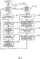
- Fig. 4 is an example flow diagram illustrating one manner in which the digital video information monitor/analyzer 14 may be configured to generate event records and a sequence of events record.
- the program illustrated in Fig. 4 is used with examples of the digital information monitor/analyzer 14 that maintain a sequence of events record using, for example, a look-up table in a memory separate from the mass storage device 24.
- the program shown in Fig. 4 is described as being performed by the example of the digital information monitor/analyzer 14 shown in Fig. 2 .
- the program shown in Fig. 4 can be used with other digital information monitor/analyzer devices.
- the write detector 62 determines if a large packet is to be stored (i.e., written to, recorded on, etc.) on the mass storage device 24 (block 150).
- Digital audio, video and image information is typically transmitted in relatively large packets.
- video program information is typically sent to the mass storage device 24 in 65,536 byte packets, whereas user configuration information and other configuration information is usually sent is much smaller packets such as, for example, 512 byte packets.
- the access detector 58 determines the location (e.g., the LBA) to which the digital information is to be written or stored (block 152) on the mass storage device 24, determines a current local time (block 154) and determines the source (e.g., the channel) associated with the information to be stored or recorded on the mass storage device 24 (block 156).
- the event record generator 56 then generates an event record containing the current local time and the source information (block 158).
- the event record generator 56 then stores the event record, preferably in the memory 66, in the sequence of events record according to the location information (e.g., in a look-up table format indexed by the location information) (block 160).
- the read detector 60 determines if a large packet of digital information is to be read from the mass storage device 24 (block 162).
- a large packet read corresponds to a playback of digital audio, video and/or image information.
- a packet containing digital audio, video and/or image information may be 65,536 bytes, which corresponds to 256 sectors.
- the IDE protocol permits the use of multiple read/write commands that enable the transmission of packets containing more than 256 sectors of digital information within a single data transaction with a mass storage device.
- the access detector 58 determines, based on digital information transmitted on the data bus 26, the location on the mass storage device 24 from which the packet is to be read (block 164).
- the event record generator 56 uses the location information to look up the previously stored event record corresponding to that location information in the sequence of events record (i.e., in the look-up table) (block 166).
- One particularly useful manner of enabling the event record generator 56 to rapidly look up the event record corresponding to the location information transmitted on the data bus 26 establishes a one-to-one correspondence between memory addresses within the memory 66 and the permissible storage locations available within the mass storage device 24.
- each LBA or C:H:S location on the mass storage device 24 may be directly mapped to an address within the memory 66.
- the time stamp generator 52 determines a current local time (e.g., a date and time of day) (block 168) and the event record generator 56 adds that current local time information to the event record found at block 166 (block 170).
- Fig. 5 is a flow diagram of another example manner in which the digital information monitor/analyzer 14 may be configured to generate a sequence of events record.
- the example program shown in Fig. 5 is used with examples of the digital information monitor/analyzer 14 that store event records as headers along with digital information on the mass storage device 24, as opposed to storing event records in a table or other data structure in a memory separate from the mass storage device 24.
- the write detector 62 determines if a large packet is to be written to (i.e., recorded on) the mass storage device 24 (block 200). Of course, if desired, a packet size restriction does not have to be implemented. If a large packet is to be written, the time stamp generator 52 determines a current local time (block 202), the access detector 58 determines the source of the packet information (block 204) and the event record generator 56 generates an event record containing the current local time information and source information (block 206).
- a header packet is formed by the event record generator 56 using the event record (block 208) and the header packet is prepended or inserted in the data stream of information written to the mass storage device 24 (block 210) so that the header packet is stored along with its corresponding data packet on the mass storage device 24 (block 212).
- the read detector 60 determines if a large packet is to be read from (e.g., played back from) the mass storage device 24 (block 214). If a large packet is to be read from the mass storage device 24, the event record generator 56 determines a current local time (e.g., a date and time of day) (block 216), extracts the header packet associated with the packet to be read (block 218) and adds the current local time to the extracted header packet to form a playback record (block 220). The event record generator 56 then stores the playback record in a sequence of events record, which may contain a plurality of playback records (block 222).
- a current local time e.g., a date and time of day
- Fig. 6 is a block diagram of an example header packet insertion/extraction apparatus 250 that may be used within the digital information monitor/analyzer 14 to carry out the example method shown in Fig. 5 .
- the header insertion/extraction apparatus 250 is serially interposed in the data bus 26 between the local data processing unit 22 and the mass storage device 24.
- the apparatus 250 includes a write detector 252, a header packet generator 254, a time stamper 256, a delay unit 258, a control unit 260, a read detector 262, switches 264, 266, 268 and 270, a playback record output 271, and an end of packet detector 272.
- the switches 264, 266, 268 and 270 are in positions A, A, D and E, respectively.
- the control unit moves switches 264 and 266 to their respective B positions.
- any digital information transmitted on the bus 26 to the mass storage device 24 is delayed by delay unit 258, which can be implemented using a plurality of shift registers or the like.
- the header packet generator 254 generates a header packet containing current local time information derived from the time stamper 256.
- the header packet may contain source information generated by one of the attachments 16 ( Fig. 1 ).
- the header packet is then transmitted to the mass storage device 24 on the data bus 26.
- the control unit 260 causes the switch 266 to move to position C, thereby enabling the data packet to be conveyed to and stored on the mass storage device 24.
- the control unit 260 returns the switches 264 and 266 to their respective A positions.
- the control unit 260 and/or read detector 262 may be used to detect if a header packet exists. If a header packet exists, the control unit 260 causes the switch 264 to be in its A position, the switch 266 to be in its D position, and the switches 268 and 270 to be in their respective E positions. The previously stored header packet is then routed to the playback record output 271.
- the end of packet detector 272 When the end of packet detector 272 detects the end of the header packet, the end of packet detector 272 sends a signal to the control unit 260, which, in turn, causes the switch 270 to move to its F position and the switch 266 to move to its A position. With the switch 270 in its F position, the time stamper 256 is enabled to provide current time information via the playback record output 271. In this manner, the playback record output 271 provides the originally recorded header packet information, which includes the time at which the data packet was written to or stored on the mass storage device 24, and a read time or playback time for the data packet.
- Fig. 7 is a flow diagram of an example manner in which the header packet insertion/extraction apparatus shown in Fig. 6 may be used within the information monitor/analyzer devices shown in Figs. 1 , 2 and 3 to generate a sequence of events record.
- the digital information monitor/analyzer 14 determines if the file size (i.e., the amount of data) associated with a pending data transfer on the data bus 26 is greater than a threshold size associated with an audio, video and/or image file (block 276). If the digital information monitor/analyzer 14 determines that the file size exceeds the threshold value, then the write detector 252 determines if a write operation is pending (block 277).
- the control unit 260 configures the switch 264 to route the file being transferred from the local data processing unit 22 to the mass storage device 24 via the data bus 26 through the delay unit 258, thereby delaying the audio, video and/or image information or content being sent via the bus 26 (block 278).
- the control unit 260 sets the switch 266 to its B position to enable the insertion of a header packet on the data bus 26 (block 279). Because the audio, video and/or image information or content is delayed, the header packet is sent to the mass storage device 24 immediately ahead of the content information and, thus, is effectively prepended to the content information.
- the prepended or inserted header packet contains time information generated by the time stamper 256 and may also contain source information and information indicating or otherwise marking the beginning and end of the header packet.
- the control unit 260 sets the switch 266 to its C position to enable the delayed audio, video and/or image content information to be conveyed or routed to the mass storage device 24 (block 280).
- the read detector 262 determines if a read operation is pending on the data bus 26 (block 281). If a read operation is pending, the control unit 260 uses the read detector 262 to determine if the beginning of the header packet is being transmitted on the data bus 26 (block 282). If the beginning of the header packet is detected (block 282), the control unit 260 sets the switches 268 and 270 to their respective E positions to strip the header information from the data bus 26 (i.e., the header information is not routed back to the local data processing unit for display, playback, etc. via a media device such as, for example, a television) (block 283).
- a media device such as, for example, a television
- the end of packet detector 272 determines if the end of the header packet has been transmitted on the data bus 26 (block 284). If the end of the header packet has not been detected (block 284), then the control unit 260 continues to route or strip the header packet information from the data bus 26 and sends it to the playback record output 271. On the other hand, if the end of packet detector 272 detects the end of the header packet, the control unit 260 sets the switches 264 and 266 to their A positions, the switch 268 to its D position and the switch 270 to its F position.
- digital audio, video and/or image content associated with the stripped header packet is routed via the data bus 26 to a media device such as, for example, the local data processing unit 22 within a DVR, PVR, etc. (block 285).
- the time stamper 256 provides time information (e.g., date and time of day information) to the playback record output 271 via the switch 270, thereby effectively attaching the time information, which in this example, is a playback time, to the header information (block 286).
- the playback record output 271 may convey the header information, including playback time information, as an event record to a central collection location such as, for example, the data logger/processor 18 (block 287).
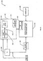
- Fig. 8 is a block diagram of an example system 300 that uses a digital information monitor/analyzer 302 in conjunction with a DVR 304, such as a TiVoTM system, and an audience measurement unit or home unit 306.
- the DVR 304 includes a video processing unit 308 and a disk drive or hard drive 310 that are coupled via a data bus 312.
- the disk drive 310 is an IDE compatible device and uses a magnetic storage medium having a storage capacity of at least eighty gigabytes. However, the disk drive 310 may optionally use other storage media, have greater or less storage capacity and may communicate with the video processing unit 308 using any desired communication protocol and platform.
- the DVR 304 may also include an infrared detector 314 that receives commands and/or other control signals from a hand-held remote control device or another device having an infrared transmitter.
- the DVR 304 is in communication with a cable or satellite television signal 316, to a television 318 and to the digital information monitor/analyzer 302.
- a source detector 320 which may, for example, be a frequency detector attachment, is in communication with the digital information monitor/analyzer 302 and provides tuning information thereto.
- the digital information monitor/analyzer 302 may optionally include an infrared transmitter 322 that enables the digital information monitor/analyzer 302 to communicate with the DVR 304 via its infrared detector 314.
- the digital information monitor/analyzer 302 may be configured identically or similarly to any of the examples of the digital information monitor/analyzer 14 shown and described in connection with Figs. 1 , 2 and 3 .
- the digital information monitor/analyzer 302 monitors the data bus 312 and generates event records containing recording times and sources and, if needed by the digital information monitor/analyzer 302, the storage locations of those event records on the disk drive 310.
- the digital information monitor/analyzer 302 adds read time, playback time or viewing time information to the event records to generate a sequence of events record that can be further analyzed, as described in greater detail below, by the digital information monitor/analyzer 302, the home unit 306 and/or a central data processing facility such as the facility 20 shown in Fig. 1 to ascertain audience viewing behaviors or habits.
- Figs. 9 through 12 Before discussing a specific example of an analysis of a sequence of events record generated by the digital information monitor/analyzer 302, a discussion of the general relationships between the various operational modes of the DVR 304 and the characteristics of a sequence of events record is provided in connection with Figs. 9 through 12 below.
- the horizontal axis represents the view time or playback time associated with the event records and the vertical axis represents the delay time (i.e., the difference between the playback or viewing time and the record time).
- Fig. 9 is a graph that depicts an example of live viewing of a video program via the DVR 304. As shown in Fig. 9 , the delay time equals zero for all view times during live viewing of a program.
- Fig. 10 is a graph that depicts an example of delayed viewing of video program via the DVR 304. As shown in Fig. 10 , the delay time is constant for all view times, indicating that a part of or the entire video program currently being viewed was previously recorded by the DVR 304 and is now being viewed.
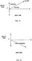
- Fig. 11 is a graph that depicts an example relationship between view time and delay time for pause and rewind operations of the DVR 304.
- a pause results in a one-for-one increase in delay time and view time and, thus, the line having a slope equal to one (i.e., at forty-five degrees) represents a paused condition of the DVR 304.
- the relationship between view time and delay time falls between the forty-five degree pause line and the vertical axis at ninety degrees, a rewind operation of the DVR 304 is indicated.
- Fig. 12 is a graph that depicts an example relationship between-view time and delay time for a fast forward operation of the DVR 304.
- the delay time decreases as the view time increases.
- a fast forward operation of the DVR 304 is indicated.
- Fig. 13 is a graph of an example viewing behavior associated with the DVR 304.
- the example graph shown in Fig. 13 may be generated based on a sequence of events record by the digital information monitor/analyzer 302 and/or by the home unit 306.
- the example viewing behavior information graphically depicted in Fig. 13 could instead be generated by a central data processing facility in communication with the home unit 306.
- the viewing behavior associated with the DVR 304 can be interpreted in light of the general operational characteristics of the DVR 304 shown in Figs. 9-12 .
- the delay time equals zero for all view times and, thus, indicates that live viewing of a viewer interface menu or a video program is occurring.
- second and third regions 402 and 404 a time shift occurs, indicating that a "go back" command or the like may have been issued by the viewer (via a hand-held remote control or the like) to the DVR 304, causing the DVR to rewind and then resume delayed playback of a video program.
- the slope equals one, indicating that the DVR 304 is paused.
- the DVR 304 resumes delayed playback of the video program.
- the slope of the characteristic is negative, indicating that a fast forward operation is in progress.
- the DVR 304 resumes delayed playback.
- the slope of the characteristic is greater than one (i.e., greater than forty-five degrees), indicating that the DVR 304 is engaged in a rewind operation.
- the DVR resumes delayed playback.
- the time delay is again zero for all view times and, thus, the DVR 304 is operating to provide live viewing of a video program.
- DVR 304 shown in Fig. 8 it may not be possible in some circumstances to distinguish live viewing of a program from paused operation of the DVR 304 by only monitoring information transmitted on the data bus 312. Specifically, when a program is viewed live (i.e., without any delay), information may in some cases only be written (i.e., there are no read operations) to the disk drive 310. Similarly, when a program is initially paused, information may, in some cases, only be written to the disk drive 310. Further, during paused operation, the last viewed video frame does not have to be read from the disk drive 310 because a refresh circuit (not shown) within the DVR 310 is used to constantly regenerate the last frame and provide it to the television 318. Consequently,-in some circumstances live viewing and paused operation will appear to be identical based on the information monitored on the data bus 312.
- Fig. 14 is a flow diagram of an example program that can be used by the digital information monitor/analyzer 14 described herein to eliminate the possibility that paused operation and live viewing operation of a DVR cannot be distinguished.
- the digital information monitor/analyzer 14 determines if the elapsed time since a last read of the disk drive 310 is greater than a predetermined threshold time (e.g., several seconds) (block 500). If the elapsed time is not greater than the predetermined threshold time (block 500), the digital information monitor/analyzer 14 reenters block 500.
- a predetermined threshold time e.g., several seconds
- the digital information monitor/analyzer 14 causes the DVR 304 to pause for a brief time such as, for example, about one-half of a second (block 502).
- the digital information monitor/analyzer 14 then causes the DVR 304 to enter playback operation (block 504).
- the digital information monitor/analyzer 14 determines if there has been a time delay (block 506) greater than a second threshold.
- a time delay exceeding the second threshold e.g., more than one second
- the digital information monitor/analyzer 14 causes the DVR 304 to enter paused operation (block 508).
- the digital information monitor/analyzer 14 determines that the time delay (block 506), if any, does not exceed the second threshold, then the DVR 304 is allowed to remain in a playback operating mode.
- the various DVR-commands required to carry out the example method shown in Fig. 14 can be transmitted to the DVR 304 by the digital information monitor/analyzer 14 via the infrared transmitter 322 and the infrared detector 314.
Landscapes
- Engineering & Computer Science (AREA)
- Signal Processing (AREA)
- Multimedia (AREA)
- Signal Processing For Digital Recording And Reproducing (AREA)
Claims (26)
- Vorrichtung zum Überwachen der Wiedergabe oder Aufnahme von Mengen an digitalen Informationen, die wenigstens Textinformationen, Bildinformationen, Videoinformationen oder Audioinformationen umfassen, auf einem digitalen Aufnahmegerät (12; 304), umfassend:einen Prozessor (18; 106); undeinen ersten Speicher (102; 104), der mit dem Prozessor (18; 106) kommuniziert, wobei der Prozessor (18; 106) dazu ausgelegt ist, Instruktionen ausführen, die auf dem ersten Speicher (102; 104) gespeichert sind, um:einen Speichervorgang einer der digitalen Informationen aus der Menge der digitalen Informationen zu erfassen, die auf einem Datenbus (26; 312) zu einem mit dem digitalen Aufnahmegerät (12; 304) verknüpften Massenspeichergerät (24; 310) übertragen werden;an einem Speicherort, der von dem Massenspeichergerät (24; 310) separiert ist, Zeitinformationen zu speichern, die dem Speichervorgang entsprechen, in Verknüpfung mit einer ersten Adresse des Speichervorgangs, und Quellinformationen, die mit der Menge an digitalen Informationen verknüpft sind, von einem Quelldetektor (320), der mit der Vorrichtung kommuniziert;basierend auf einem nachfolgenden Überwachen des Datenbusses (26; 312), einen Lesevorgang zu detektieren, der die Menge an digitalen Informationen von dem Massenspeichergerät (24; 310) abruft;eine zweite Adresse, die dem Lesevorgang entspricht, mit der an dem Speicherort gespeicherten ersten Adresse zu vergleichen; undfalls die zweite Adresse zur ersten Adresse passt, eine Abspielzeit der Menge an digitalen Informationen entsprechend dem Lesevorgang in Verknüpfung mit den Zeitinformationen zu speichern, die dem Speichervorgang entsprechen.
- Vorrichtung nach Anspruch 1, wobei das Massenspeichergerät (24; 310) wenigstens ein magnetisches Speichermedium oder ein optisches Speichermedium umfasst.
- Vorrichtung nach Anspruch 1, wobei die erste Adresse einem Zylinder, Kopf und Sektor eines Plattenlaufwerks entspricht.
- Vorrichtung nach Anspruch 1, wobei die Zeitinformationen und die erste Adresse selektiv vom Prozessor (18; 106) gespeichert werden, in Reaktion auf ein Bestimmen, dass die mit dem Speichervorgang verknüpften Informationen einen Datengrößenschwellwert überschreiten, und wobei der Prozessor (18; 106) dazu ausgelegt ist, die in dem ersten Speicher (102; 104) gespeicherten Instruktionen auszuführen, um selektiv einen weiteren Speichervorgang zu ignorieren, der mit zweiten Informationen verknüpft ist, die den Datengrößenschwellwert nicht überschreiten.
- Vorrichtung nach Anspruch 1, wobei der Prozessor (18; 106) und der erste Speicher (102; 104) von dem digitalen Aufnahmegerät (12; 304) separiert sind.
- Vorrichtung nach Anspruch 1, wobei der erste Speicher (102; 104) in einem einzelnen Gerät integriert ist und ein zweiter Speicher den Speicherort umfasst.
- Vorrichtung nach Anspruch 1, wobei die Zeitinformationen mit einer aktuellen Ortszeit verknüpft sind.
- Vorrichtung nach Anspruch 1, wobei der Prozessor (18; 106) dazu ausgelegt ist, die auf dem ersten Speicher (102; 104) gespeicherten Instruktionen auszuführen, um die Quellinformationen von einem Frequenzdetektoranhang zu empfangen.
- Vorrichtung nach Anspruch 1, wobei der Prozessor (18; 106) dazu ausgelegt ist, die auf dem ersten Speicher (102; 104) gespeicherten Instruktionen auszuführen, um Fernsehkanalinformationen der Mengen an digitalen Informationen in Verknüpfung mit den ersten Zeitinformationen und der ersten Adresse zu speichern.
- Vorrichtung nach Anspruch 1, wobei das Massenspeichergerät (24; 310) sich in dem digitalen Aufnahmegerät (12; 304) befindet.
- Verfahren zum Überwachen der Wiedergabe oder Aufnahme von Mengen an digitalen Informationen, die wenigstens Textinformationen, Bildinformationen, Videoinformationen oder Audioinformationen umfassen, auf einem digitalen Aufnahmegerät (12; 304), umfassend:Erfassen eines Speichervorgangs einer der digitalen Informationen aus der Menge der digitalen Informationen, die auf einem Datenbus (26; 312) zu einem mit dem digitalen Aufnahmegerät (12; 304) verknüpften Massenspeichergerät (24; 310) übertragen werden;an einem Speicherort, der von dem Massenspeichergerät (24; 310) separiert ist, Speichern von Zeitinformationen, die dem Speichervorgang entsprechen, in Verknüpfung mit einer ersten Adresse des Speichervorgangs, und Quellinformationen, die mit der Menge an digitalen Informationen verknüpft sind, von einem Quelldetektor (320), der nicht mit dem Datenbus kommuniziert;basierend auf dem nachfolgenden Überwachen des Datenbusses (26; 312), Detektieren eines Speichervorgangs, der die Menge an digitalen Informationen von dem Massenspeichergerät (24; 310) abruft;Vergleichen einer zweiten Adresse, die dem Lesevorgang entspricht, mit der an dem Speicherort gespeicherten ersten Adresse; undfalls die zweite Adresse zur ersten Adresse passt, Speichern einer Abspielzeit der Mengen an digitalen Informationen entsprechend dem Lesevorgang in Verknüpfung mit den Zeitinformationen, die dem Speichervorgang entsprechen.
- Verfahren nach Anspruch 11, wobei die Abspielzeit eine aktuelle Ortszeit ist.
- Verfahren nach Anspruch 11, wobei die erste Adresse einem Zylinder, Kopf und Sektor eines Plattenlaufwerks entspricht.
- Verfahren nach Anspruch 11, wobei der Speicherort, der die Zeitinformationen, die erste Adresse und die Quellinformationen speichert, sich in einem Speicher befindet, der von dem digitalen Aufnahmegerät (12; 304) separiert ist.
- Verfahren nach Anspruch 11, wobei die Zeitinformationen und die erste Adresse selektiv gespeichert werden in Reaktion auf ein Bestimmen, dass die mit dem Speichervorgang verknüpften Informationen einen Datengrößenschwellwert überschreiten, und wobei der Prozessor (18; 106) dazu ausgelegt ist, selektiv einen weiteren Speichervorgang zu ignorieren, der mit zweiten Informationen verknüpft ist, die den Datengrößenschwellwert nicht überschreiten.
- Verfahren nach Anspruch 11, ferner umfassend das Speichern von Fernsehkanalinformationen von den Mengen an digitalen Informationen, die mit den Zeitinformationen und der ersten Adresse verknüpft sind.
- Vorrichtung für das Überwachen der Wiedergabe oder Aufnahme von Mengen an digitalen Informationen, die wenigstens Textinformationen, Bildinformationen, Videoinformationen oder Audioinformationen umfassen, auf einem Aufnahmegerät (12, 304), umfassend:einen Zugriffs-Detektor (58), um einen Speichervorgang einer der digitalen Informationen aus der Menge der digitalen Informationen zu erfassen, die auf einem Datenbus (26; 312) zu einem mit dem digitalen Aufnahmegerät (12; 304) verknüpften Massenspeichergerät (24; 310) übertragen werden;eine Quellidentifizierungseinheit, um Quellinformationen der Menge der digitalen Informationen bereitzustellen, die im Massenspeichergerät gespeichert werden; undeinen Ereigniseintrag-Generator (56), der mit dem Zugriffs-Detektor (58) kommuniziert, wobei der Ereigniseintrag-Generator dazu dient:an einem Speicherort, der von dem Massenspeichergerät (24; 310) separiert ist, Zeitinformationen zu speichern, die dem Speichervorgang entsprechen, in Verknüpfung mit einer ersten Adresse des Speichervorgangs, und Quellinformationen, die mit der Menge an digitalen Informationen verknüpft sind, von einem Quelldetektor (320), der mit der Vorrichtung kommuniziert;die erste Adresse, die an dem Speicherort gespeichert ist, mit einer zweiten Adresse zu vergleichen, die einem Lesevorgang entspricht, der von dem Zugriffs-Detektor (58) basierend auf dem nachfolgenden Überwachen des Datenbusses (26; 312) detektiert wurde; undfalls die erste Adresse zur zweiten Adresse passt, eine Abspielzeit der Menge an digitalen Informationen entsprechend dem Lesevorgang in Verknüpfung mit den Zeitinformationen zu speichern, die dem Speichervorgang entspricht.
- Vorrichtung nach Anspruch 17, wobei die erste Adresse wenigstens eine logische Blockadresse oder Zylinder/Kopf/Sektor-Informationen umfasst.
- Vorrichtung nach Anspruch 17, wobei der Zugriffs-Detektor (58) dazu dient, die über den Datenbus (26; 312) an das Massenspeichergerät (24; 310) übertragenen Steuersignale zu überwachen, um den Speicher- und/oder den Lesevorgang zu detektieren.
- Vorrichtung nach Anspruch 19, wobei das Massenspeichergerät (24; 310) ein Plattenlaufwerk ist, und wobei der Datenbus (26; 312) wenigstens teilweise auf einem Integrated Drive Electronics-Standard basiert und die überwachten Steuersignale Steuerregister-Auswahlsignale enthalten.
- Vorrichtung nach Anspruch 17, wobei der Zugriffs-Detektor (58) dazu ausgelegt ist, die über den Datenbus (26; 312) an das Massenspeichergerät (24; 310) übertragenen Steuersignale zu überwachen, um die erste Adresse auf dem Massenspeichergerät (24; 310) zu bestimmen, unter der die Menge an digitalen Informationen gespeichert werden soll.
- Vorrichtung nach Anspruch 17, wobei der Ereigniseintrag-Generator (56) dazu ausgelegt ist, die Zeitinformationen und die erste Adresse zu übertragen, die zusammen mit einem entsprechenden Teil der Menge an digitalen Informationen auf dem Massenspeichergerät (24; 310) gespeichert werden sollen.
- Vorrichtung nach Anspruch 22, wobei die Zeitinformationen und die erste Adresse als Header mit dem entsprechenden Teil der Menge an digitalen Informationen auf dem Massenspeichergerät (24; 310) gespeichert werden.
- Vorrichtung nach Anspruch 17, wobei der Ereigniseintrag-Generator (56) dazu dient, die Zeitinformationen und die erste Adresse auf einem Speicher zu speichern, der von dem digitalen Aufnahmegerät (12; 304) separiert ist.
- Vorrichtung nach Anspruch 17, wobei die Zeitinformationen und die erste Adresse selektiv gespeichert werden, in Reaktion auf ein Bestimmen, dass die mit dem Speichervorgang verknüpften Informationen einen Datengrößenschwellwert überschreiten, und wobei der Ereigniseintrag-Generator dazu ausgelegt ist, selektiv einen weiteren Speichervorgang zu ignorieren, der mit zweiten Informationen verknüpft ist, die den Datengrößenschwellwert nicht überschreiten.
- Maschinenzugängliches Medium, das Instruktionen speichert, die, wenn sie ausgeführt werden, bewirken, dass die Maschine Vorgänge nach einem der Ansprüche 11 bis 17 ausführt.
Priority Applications (1)
| Application Number | Priority Date | Filing Date | Title |
|---|---|---|---|
| EP13001703.1A EP2621164B1 (de) | 2002-11-27 | 2002-11-27 | Vorrichtung und Verfahren zur Nachverfolgung und Analyse von digitalen Aufzeichnungsgerät-Ereignissequenzen |
Applications Claiming Priority (1)
| Application Number | Priority Date | Filing Date | Title |
|---|---|---|---|
| PCT/US2002/038012 WO2004051997A1 (en) | 2002-11-27 | 2002-11-27 | Apparatus and methods for tracking and analyzing digital recording device event sequences |
Related Child Applications (2)
| Application Number | Title | Priority Date | Filing Date |
|---|---|---|---|
| EP13001703.1A Division-Into EP2621164B1 (de) | 2002-11-27 | 2002-11-27 | Vorrichtung und Verfahren zur Nachverfolgung und Analyse von digitalen Aufzeichnungsgerät-Ereignissequenzen |
| EP13001703.1A Division EP2621164B1 (de) | 2002-11-27 | 2002-11-27 | Vorrichtung und Verfahren zur Nachverfolgung und Analyse von digitalen Aufzeichnungsgerät-Ereignissequenzen |
Publications (3)
| Publication Number | Publication Date |
|---|---|
| EP1568218A1 EP1568218A1 (de) | 2005-08-31 |
| EP1568218A4 EP1568218A4 (de) | 2009-08-26 |
| EP1568218B1 true EP1568218B1 (de) | 2017-04-12 |
Family
ID=32467110
Family Applications (1)
| Application Number | Title | Priority Date | Filing Date |
|---|---|---|---|
| EP02784621.1A Expired - Lifetime EP1568218B1 (de) | 2002-11-27 | 2002-11-27 | Vorrichtung und verfahren zur nachverfolgung und analyse von digitalen aufzeichnungsgerät-ereignissequenzen |
Country Status (4)
| Country | Link |
|---|---|
| EP (1) | EP1568218B1 (de) |
| AU (1) | AU2002346553A1 (de) |
| CA (1) | CA2507317C (de) |
| WO (1) | WO2004051997A1 (de) |
Families Citing this family (16)
| Publication number | Priority date | Publication date | Assignee | Title |
|---|---|---|---|---|
| US8204353B2 (en) | 2002-11-27 | 2012-06-19 | The Nielsen Company (Us), Llc | Apparatus and methods for tracking and analyzing digital recording device event sequences |
| US7248777B2 (en) | 2003-04-17 | 2007-07-24 | Nielsen Media Research, Inc. | Methods and apparatus to detect content skipping by a consumer of a recorded program |
| EP1792422A4 (de) | 2004-02-17 | 2012-10-17 | Nielsen Media Res Inc | Verfahren und vorrichtung zur ermittlung der zuschauer-sehgewohnheiten für aufgezeichnete programme |
| WO2005079941A1 (en) | 2004-02-17 | 2005-09-01 | Nielsen Media Research, Inc. Et Al. | Methods and apparatus for monitoring video games |
| US7594242B2 (en) | 2004-02-23 | 2009-09-22 | The Nielsen Company (Us), Llc | Methods and apparatus to detect an internally generated signal mode of a local media playback device |
| CA2563834C (en) | 2004-04-23 | 2016-08-16 | Nielsen Media Research, Inc. | Methods and apparatus to maintain audience privacy while determining viewing of video-on-demand programs |
| AU2005269957B2 (en) * | 2004-07-02 | 2011-09-22 | The Nielsen Company (Us), Llc | Methods and apparatus for identifying viewing information associated with a digital media device |
| MX2007015263A (es) | 2005-06-03 | 2008-02-22 | Nielsen Media Res Inc | Metodos y aparato para detectar un episodio de cronocorrimiento asociado con la presentacion del contenido de medios. |
| US9015740B2 (en) | 2005-12-12 | 2015-04-21 | The Nielsen Company (Us), Llc | Systems and methods to wirelessly meter audio/visual devices |
| US8959556B2 (en) | 2008-09-29 | 2015-02-17 | The Nielsen Company (Us), Llc | Methods and apparatus for determining the operating state of audio-video devices |
| US9124769B2 (en) | 2008-10-31 | 2015-09-01 | The Nielsen Company (Us), Llc | Methods and apparatus to verify presentation of media content |
| EP2209236A1 (de) | 2009-01-16 | 2010-07-21 | GfK Telecontrol AG | Vorrichtung zum Sammeln von Zuhörererfassungsdaten |
| US8307006B2 (en) | 2010-06-30 | 2012-11-06 | The Nielsen Company (Us), Llc | Methods and apparatus to obtain anonymous audience measurement data from network server data for particular demographic and usage profiles |
| US8677385B2 (en) | 2010-09-21 | 2014-03-18 | The Nielsen Company (Us), Llc | Methods, apparatus, and systems to collect audience measurement data |
| US9692535B2 (en) | 2012-02-20 | 2017-06-27 | The Nielsen Company (Us), Llc | Methods and apparatus for automatic TV on/off detection |
| US10045082B2 (en) | 2015-07-02 | 2018-08-07 | The Nielsen Company (Us), Llc | Methods and apparatus to correct errors in audience measurements for media accessed using over-the-top devices |
Citations (1)
| Publication number | Priority date | Publication date | Assignee | Title |
|---|---|---|---|---|
| WO1999063698A2 (en) * | 1998-05-15 | 1999-12-09 | Interval Research Corporation | Synchronous network for digital media streams |
Family Cites Families (7)
| Publication number | Priority date | Publication date | Assignee | Title |
|---|---|---|---|---|
| US4367525A (en) | 1980-06-06 | 1983-01-04 | Tesdata Systems Corporation | CPU Channel monitoring system |
| US5457694A (en) | 1993-06-25 | 1995-10-10 | Smith; Dale J. | Method and apparatus for analyzing the ATA (IDE) interface |
| JPH07281930A (ja) | 1994-04-08 | 1995-10-27 | Nec Corp | 情報処理装置動作測定解析システム |
| JPH10276160A (ja) * | 1997-03-31 | 1998-10-13 | Sony Corp | 番組制作送出装置 |
| US6026218A (en) * | 1997-06-11 | 2000-02-15 | Sun Microsystems, Inc. | Computer system employing a bus snooping multimedia subsystem for implementing video multicast transactions |
| US6202210B1 (en) * | 1998-08-21 | 2001-03-13 | Sony Corporation Of Japan | Method and system for collecting data over a 1394 network to support analysis of consumer behavior, marketing and customer support |
| US6662176B2 (en) * | 2001-05-07 | 2003-12-09 | Hewlett-Packard Development Company, L.P. | Database indexing and rolling storage method for time-stamped normalized event data |
-
2002
- 2002-11-27 CA CA2507317A patent/CA2507317C/en not_active Expired - Lifetime
- 2002-11-27 EP EP02784621.1A patent/EP1568218B1/de not_active Expired - Lifetime
- 2002-11-27 WO PCT/US2002/038012 patent/WO2004051997A1/en not_active Ceased
- 2002-11-27 AU AU2002346553A patent/AU2002346553A1/en not_active Abandoned
Patent Citations (1)
| Publication number | Priority date | Publication date | Assignee | Title |
|---|---|---|---|---|
| WO1999063698A2 (en) * | 1998-05-15 | 1999-12-09 | Interval Research Corporation | Synchronous network for digital media streams |
Also Published As
| Publication number | Publication date |
|---|---|
| EP1568218A1 (de) | 2005-08-31 |
| CA2507317A1 (en) | 2004-06-17 |
| CA2507317C (en) | 2011-09-20 |
| WO2004051997A1 (en) | 2004-06-17 |
| EP1568218A4 (de) | 2009-08-26 |
| AU2002346553A1 (en) | 2004-06-23 |
Similar Documents
| Publication | Publication Date | Title |
|---|---|---|
| US9991980B2 (en) | Apparatus and methods for tracking and analyzing digital recording device event sequences | |
| EP1568218B1 (de) | Vorrichtung und verfahren zur nachverfolgung und analyse von digitalen aufzeichnungsgerät-ereignissequenzen | |
| US11368750B2 (en) | Methods and apparatus for detecting space-shifted media associated with a digital recording/playback device | |
| US8752115B2 (en) | System and method for aggregating commercial navigation information | |
| CA2556548C (en) | Methods and apparatus to determine audience viewing of recorded programs | |
| US9392227B2 (en) | Methods and apparatus to export tuning data collected in a receiving device | |
| US20070186229A1 (en) | Methods and apparatus for identifying viewing information associated with a digital media device | |
| US7937728B2 (en) | Retrieving lost content for a scheduled program | |
| EP2621164B1 (de) | Vorrichtung und Verfahren zur Nachverfolgung und Analyse von digitalen Aufzeichnungsgerät-Ereignissequenzen | |
| EP2439740A1 (de) | Informationsverarbeitungsvorrichtung und Informationsverarbeitungsverfahren |
Legal Events
| Date | Code | Title | Description |
|---|---|---|---|
| PUAI | Public reference made under article 153(3) epc to a published international application that has entered the european phase |
Free format text: ORIGINAL CODE: 0009012 |
|
| 17P | Request for examination filed |
Effective date: 20050613 |
|
| AK | Designated contracting states |
Kind code of ref document: A1 Designated state(s): AT BE BG CH CY CZ DE DK EE ES FI FR GB GR IE IT LI LU MC NL PT SE SK TR |
|
| AX | Request for extension of the european patent |
Extension state: AL LT LV MK RO SI |
|
| DAX | Request for extension of the european patent (deleted) | ||
| A4 | Supplementary search report drawn up and despatched |
Effective date: 20090728 |
|
| 17Q | First examination report despatched |
Effective date: 20110408 |
|
| GRAP | Despatch of communication of intention to grant a patent |
Free format text: ORIGINAL CODE: EPIDOSNIGR1 |
|
| INTG | Intention to grant announced |
Effective date: 20160602 |
|
| RAP1 | Party data changed (applicant data changed or rights of an application transferred) |
Owner name: NIELSEN MEDIA RESEARCH, INC. |
|
| GRAJ | Information related to disapproval of communication of intention to grant by the applicant or resumption of examination proceedings by the epo deleted |
Free format text: ORIGINAL CODE: EPIDOSDIGR1 |
|
| GRAS | Grant fee paid |
Free format text: ORIGINAL CODE: EPIDOSNIGR3 |
|
| INTC | Intention to grant announced (deleted) | ||
| GRAP | Despatch of communication of intention to grant a patent |
Free format text: ORIGINAL CODE: EPIDOSNIGR1 |
|
| INTG | Intention to grant announced |
Effective date: 20161129 |
|
| GRAA | (expected) grant |
Free format text: ORIGINAL CODE: 0009210 |
|
| AK | Designated contracting states |
Kind code of ref document: B1 Designated state(s): AT BE BG CH CY CZ DE DK EE ES FI FR GB GR IE IT LI LU MC NL PT SE SK TR |
|
| REG | Reference to a national code |
Ref country code: GB Ref legal event code: FG4D |
|
| REG | Reference to a national code |
Ref country code: CH Ref legal event code: EP |
|
| REG | Reference to a national code |
Ref country code: IE Ref legal event code: FG4D |
|
| REG | Reference to a national code |
Ref country code: AT Ref legal event code: REF Ref document number: 884885 Country of ref document: AT Kind code of ref document: T Effective date: 20170515 |
|
| REG | Reference to a national code |
Ref country code: DE Ref legal event code: R096 Ref document number: 60248811 Country of ref document: DE |
|
| REG | Reference to a national code |
Ref country code: NL Ref legal event code: MP Effective date: 20170412 |
|
| REG | Reference to a national code |
Ref country code: AT Ref legal event code: MK05 Ref document number: 884885 Country of ref document: AT Kind code of ref document: T Effective date: 20170412 |
|
| PG25 | Lapsed in a contracting state [announced via postgrant information from national office to epo] |
Ref country code: NL Free format text: LAPSE BECAUSE OF FAILURE TO SUBMIT A TRANSLATION OF THE DESCRIPTION OR TO PAY THE FEE WITHIN THE PRESCRIBED TIME-LIMIT Effective date: 20170412 |
|
| PG25 | Lapsed in a contracting state [announced via postgrant information from national office to epo] |
Ref country code: ES Free format text: LAPSE BECAUSE OF FAILURE TO SUBMIT A TRANSLATION OF THE DESCRIPTION OR TO PAY THE FEE WITHIN THE PRESCRIBED TIME-LIMIT Effective date: 20170412 Ref country code: FI Free format text: LAPSE BECAUSE OF FAILURE TO SUBMIT A TRANSLATION OF THE DESCRIPTION OR TO PAY THE FEE WITHIN THE PRESCRIBED TIME-LIMIT Effective date: 20170412 Ref country code: AT Free format text: LAPSE BECAUSE OF FAILURE TO SUBMIT A TRANSLATION OF THE DESCRIPTION OR TO PAY THE FEE WITHIN THE PRESCRIBED TIME-LIMIT Effective date: 20170412 Ref country code: GR Free format text: LAPSE BECAUSE OF FAILURE TO SUBMIT A TRANSLATION OF THE DESCRIPTION OR TO PAY THE FEE WITHIN THE PRESCRIBED TIME-LIMIT Effective date: 20170713 |
|
| PG25 | Lapsed in a contracting state [announced via postgrant information from national office to epo] |
Ref country code: SE Free format text: LAPSE BECAUSE OF FAILURE TO SUBMIT A TRANSLATION OF THE DESCRIPTION OR TO PAY THE FEE WITHIN THE PRESCRIBED TIME-LIMIT Effective date: 20170412 Ref country code: BG Free format text: LAPSE BECAUSE OF FAILURE TO SUBMIT A TRANSLATION OF THE DESCRIPTION OR TO PAY THE FEE WITHIN THE PRESCRIBED TIME-LIMIT Effective date: 20170712 |
|
| REG | Reference to a national code |
Ref country code: DE Ref legal event code: R097 Ref document number: 60248811 Country of ref document: DE |
|
| PG25 | Lapsed in a contracting state [announced via postgrant information from national office to epo] |
Ref country code: CZ Free format text: LAPSE BECAUSE OF FAILURE TO SUBMIT A TRANSLATION OF THE DESCRIPTION OR TO PAY THE FEE WITHIN THE PRESCRIBED TIME-LIMIT Effective date: 20170412 Ref country code: EE Free format text: LAPSE BECAUSE OF FAILURE TO SUBMIT A TRANSLATION OF THE DESCRIPTION OR TO PAY THE FEE WITHIN THE PRESCRIBED TIME-LIMIT Effective date: 20170412 Ref country code: SK Free format text: LAPSE BECAUSE OF FAILURE TO SUBMIT A TRANSLATION OF THE DESCRIPTION OR TO PAY THE FEE WITHIN THE PRESCRIBED TIME-LIMIT Effective date: 20170412 Ref country code: DK Free format text: LAPSE BECAUSE OF FAILURE TO SUBMIT A TRANSLATION OF THE DESCRIPTION OR TO PAY THE FEE WITHIN THE PRESCRIBED TIME-LIMIT Effective date: 20170412 |
|
| PLBE | No opposition filed within time limit |
Free format text: ORIGINAL CODE: 0009261 |
|
| STAA | Information on the status of an ep patent application or granted ep patent |
Free format text: STATUS: NO OPPOSITION FILED WITHIN TIME LIMIT |
|
| 26N | No opposition filed |
Effective date: 20180115 |
|
| PG25 | Lapsed in a contracting state [announced via postgrant information from national office to epo] |
Ref country code: MC Free format text: LAPSE BECAUSE OF FAILURE TO SUBMIT A TRANSLATION OF THE DESCRIPTION OR TO PAY THE FEE WITHIN THE PRESCRIBED TIME-LIMIT Effective date: 20170412 |
|
| GBPC | Gb: european patent ceased through non-payment of renewal fee |
Effective date: 20171127 |
|
| PG25 | Lapsed in a contracting state [announced via postgrant information from national office to epo] |
Ref country code: LI Free format text: LAPSE BECAUSE OF NON-PAYMENT OF DUE FEES Effective date: 20171130 Ref country code: CH Free format text: LAPSE BECAUSE OF NON-PAYMENT OF DUE FEES Effective date: 20171130 |
|
| PG25 | Lapsed in a contracting state [announced via postgrant information from national office to epo] |
Ref country code: LU Free format text: LAPSE BECAUSE OF NON-PAYMENT OF DUE FEES Effective date: 20171127 |
|
| REG | Reference to a national code |
Ref country code: FR Ref legal event code: ST Effective date: 20180731 Ref country code: BE Ref legal event code: MM Effective date: 20171130 |
|
| REG | Reference to a national code |
Ref country code: IE Ref legal event code: MM4A |
|
| PG25 | Lapsed in a contracting state [announced via postgrant information from national office to epo] |
Ref country code: FR Free format text: LAPSE BECAUSE OF NON-PAYMENT OF DUE FEES Effective date: 20171130 Ref country code: IE Free format text: LAPSE BECAUSE OF NON-PAYMENT OF DUE FEES Effective date: 20171127 |
|
| PG25 | Lapsed in a contracting state [announced via postgrant information from national office to epo] |
Ref country code: GB Free format text: LAPSE BECAUSE OF NON-PAYMENT OF DUE FEES Effective date: 20171127 Ref country code: BE Free format text: LAPSE BECAUSE OF NON-PAYMENT OF DUE FEES Effective date: 20171130 |
|
| PG25 | Lapsed in a contracting state [announced via postgrant information from national office to epo] |
Ref country code: CY Free format text: LAPSE BECAUSE OF NON-PAYMENT OF DUE FEES Effective date: 20170412 |
|
| PG25 | Lapsed in a contracting state [announced via postgrant information from national office to epo] |
Ref country code: TR Free format text: LAPSE BECAUSE OF FAILURE TO SUBMIT A TRANSLATION OF THE DESCRIPTION OR TO PAY THE FEE WITHIN THE PRESCRIBED TIME-LIMIT Effective date: 20170412 |
|
| PG25 | Lapsed in a contracting state [announced via postgrant information from national office to epo] |
Ref country code: PT Free format text: LAPSE BECAUSE OF FAILURE TO SUBMIT A TRANSLATION OF THE DESCRIPTION OR TO PAY THE FEE WITHIN THE PRESCRIBED TIME-LIMIT Effective date: 20170412 |
|
| PGFP | Annual fee paid to national office [announced via postgrant information from national office to epo] |
Ref country code: DE Payment date: 20211126 Year of fee payment: 20 |
|
| PGFP | Annual fee paid to national office [announced via postgrant information from national office to epo] |
Ref country code: IT Payment date: 20211122 Year of fee payment: 20 |
|
| REG | Reference to a national code |
Ref country code: DE Ref legal event code: R071 Ref document number: 60248811 Country of ref document: DE |