EP1568176B1 - Verfahren der Datenübertragung zwischen einem ersten und einem zweiten Telekommunikationssystem, Telekommunikationsanordnung und Telekommunikations-Endsystem zur Durchführung des Verfahrens - Google Patents
Verfahren der Datenübertragung zwischen einem ersten und einem zweiten Telekommunikationssystem, Telekommunikationsanordnung und Telekommunikations-Endsystem zur Durchführung des Verfahrens Download PDFInfo
- Publication number
- EP1568176B1 EP1568176B1 EP03782125A EP03782125A EP1568176B1 EP 1568176 B1 EP1568176 B1 EP 1568176B1 EP 03782125 A EP03782125 A EP 03782125A EP 03782125 A EP03782125 A EP 03782125A EP 1568176 B1 EP1568176 B1 EP 1568176B1
- Authority
- EP
- European Patent Office
- Prior art keywords
- data
- end system
- link
- links
- logical
- Prior art date
- Legal status (The legal status is an assumption and is not a legal conclusion. Google has not performed a legal analysis and makes no representation as to the accuracy of the status listed.)
- Expired - Lifetime
Links
- 238000000034 method Methods 0.000 title claims abstract description 87
- 230000005540 biological transmission Effects 0.000 claims abstract description 84
- 230000006854 communication Effects 0.000 claims abstract description 59
- 238000004891 communication Methods 0.000 claims abstract description 34
- 230000015556 catabolic process Effects 0.000 claims description 27
- 238000005538 encapsulation Methods 0.000 claims description 11
- 230000008569 process Effects 0.000 claims description 8
- 230000036962 time dependent Effects 0.000 claims description 3
- 238000012544 monitoring process Methods 0.000 claims description 2
- 238000012795 verification Methods 0.000 claims description 2
- 230000036961 partial effect Effects 0.000 abstract description 15
- 230000001960 triggered effect Effects 0.000 abstract description 2
- 238000012546 transfer Methods 0.000 description 12
- 238000010276 construction Methods 0.000 description 11
- 238000006731 degradation reaction Methods 0.000 description 10
- 230000032258 transport Effects 0.000 description 10
- 230000008878 coupling Effects 0.000 description 8
- 238000010168 coupling process Methods 0.000 description 8
- 238000005859 coupling reaction Methods 0.000 description 8
- 238000005516 engineering process Methods 0.000 description 6
- 230000009467 reduction Effects 0.000 description 6
- 230000011664 signaling Effects 0.000 description 6
- 238000011144 upstream manufacturing Methods 0.000 description 5
- 230000002441 reversible effect Effects 0.000 description 4
- 230000008901 benefit Effects 0.000 description 3
- 150000001875 compounds Chemical class 0.000 description 3
- 230000000694 effects Effects 0.000 description 3
- 238000007726 management method Methods 0.000 description 3
- 230000007246 mechanism Effects 0.000 description 3
- 241001136792 Alle Species 0.000 description 2
- 230000008859 change Effects 0.000 description 2
- 238000012790 confirmation Methods 0.000 description 2
- 230000001934 delay Effects 0.000 description 2
- 230000014759 maintenance of location Effects 0.000 description 2
- 230000002829 reductive effect Effects 0.000 description 2
- 230000003466 anti-cipated effect Effects 0.000 description 1
- 210000000988 bone and bone Anatomy 0.000 description 1
- 238000013144 data compression Methods 0.000 description 1
- 230000006837 decompression Effects 0.000 description 1
- 230000007423 decrease Effects 0.000 description 1
- 230000000593 degrading effect Effects 0.000 description 1
- 230000003111 delayed effect Effects 0.000 description 1
- 230000001419 dependent effect Effects 0.000 description 1
- 238000011161 development Methods 0.000 description 1
- 238000005265 energy consumption Methods 0.000 description 1
- 238000009432 framing Methods 0.000 description 1
- 230000008520 organization Effects 0.000 description 1
- 238000004806 packaging method and process Methods 0.000 description 1
- 230000002688 persistence Effects 0.000 description 1
- 238000011084 recovery Methods 0.000 description 1
- 230000004044 response Effects 0.000 description 1
- 238000004904 shortening Methods 0.000 description 1
- 230000003068 static effect Effects 0.000 description 1
- 230000001360 synchronised effect Effects 0.000 description 1
Images



Classifications
-
- H—ELECTRICITY
- H04—ELECTRIC COMMUNICATION TECHNIQUE
- H04L—TRANSMISSION OF DIGITAL INFORMATION, e.g. TELEGRAPHIC COMMUNICATION
- H04L67/00—Network arrangements or protocols for supporting network services or applications
- H04L67/14—Session management
-
- H—ELECTRICITY
- H04—ELECTRIC COMMUNICATION TECHNIQUE
- H04L—TRANSMISSION OF DIGITAL INFORMATION, e.g. TELEGRAPHIC COMMUNICATION
- H04L69/00—Network arrangements, protocols or services independent of the application payload and not provided for in the other groups of this subclass
- H04L69/16—Implementation or adaptation of Internet protocol [IP], of transmission control protocol [TCP] or of user datagram protocol [UDP]
- H04L69/161—Implementation details of TCP/IP or UDP/IP stack architecture; Specification of modified or new header fields
-
- H—ELECTRICITY
- H04—ELECTRIC COMMUNICATION TECHNIQUE
- H04L—TRANSMISSION OF DIGITAL INFORMATION, e.g. TELEGRAPHIC COMMUNICATION
- H04L69/00—Network arrangements, protocols or services independent of the application payload and not provided for in the other groups of this subclass
- H04L69/16—Implementation or adaptation of Internet protocol [IP], of transmission control protocol [TCP] or of user datagram protocol [UDP]
- H04L69/168—Implementation or adaptation of Internet protocol [IP], of transmission control protocol [TCP] or of user datagram protocol [UDP] specially adapted for link layer protocols, e.g. asynchronous transfer mode [ATM], synchronous optical network [SONET] or point-to-point protocol [PPP]
-
- H—ELECTRICITY
- H04—ELECTRIC COMMUNICATION TECHNIQUE
- H04L—TRANSMISSION OF DIGITAL INFORMATION, e.g. TELEGRAPHIC COMMUNICATION
- H04L69/00—Network arrangements, protocols or services independent of the application payload and not provided for in the other groups of this subclass
- H04L69/30—Definitions, standards or architectural aspects of layered protocol stacks
- H04L69/32—Architecture of open systems interconnection [OSI] 7-layer type protocol stacks, e.g. the interfaces between the data link level and the physical level
- H04L69/322—Intralayer communication protocols among peer entities or protocol data unit [PDU] definitions
-
- H—ELECTRICITY
- H04—ELECTRIC COMMUNICATION TECHNIQUE
- H04L—TRANSMISSION OF DIGITAL INFORMATION, e.g. TELEGRAPHIC COMMUNICATION
- H04L69/00—Network arrangements, protocols or services independent of the application payload and not provided for in the other groups of this subclass
- H04L69/30—Definitions, standards or architectural aspects of layered protocol stacks
- H04L69/32—Architecture of open systems interconnection [OSI] 7-layer type protocol stacks, e.g. the interfaces between the data link level and the physical level
- H04L69/322—Intralayer communication protocols among peer entities or protocol data unit [PDU] definitions
- H04L69/329—Intralayer communication protocols among peer entities or protocol data unit [PDU] definitions in the application layer [OSI layer 7]
-
- H—ELECTRICITY
- H04—ELECTRIC COMMUNICATION TECHNIQUE
- H04Q—SELECTING
- H04Q2213/00—Indexing scheme relating to selecting arrangements in general and for multiplex systems
- H04Q2213/13204—Protocols
-
- H—ELECTRICITY
- H04—ELECTRIC COMMUNICATION TECHNIQUE
- H04Q—SELECTING
- H04Q2213/00—Indexing scheme relating to selecting arrangements in general and for multiplex systems
- H04Q2213/1327—Release and resetting of connection
-
- H—ELECTRICITY
- H04—ELECTRIC COMMUNICATION TECHNIQUE
- H04Q—SELECTING
- H04Q2213/00—Indexing scheme relating to selecting arrangements in general and for multiplex systems
- H04Q2213/13298—Local loop systems, access network
-
- H—ELECTRICITY
- H04—ELECTRIC COMMUNICATION TECHNIQUE
- H04Q—SELECTING
- H04Q2213/00—Indexing scheme relating to selecting arrangements in general and for multiplex systems
- H04Q2213/13389—LAN, internet
Definitions
- KPT coupled-pulse
- short-hold the technique known by the term “short-hold” in that, unlike this technique, which only uses TK technology. Considered devices and physical connections - can also other TK systems and higher logical connections and associations for similar but more extensive tasks can be used and thus allows to achieve much greater benefits.
- logical connections represent the "logical layers" of each communication process.
- layer 7 the communication process may include other logical “application layers” that are not generally considered by the OSI reference model: this logical application layering may be fundamentally different from application to application, whereas the logical OSI model layering is basically the same for all communications.
- the company AVM Computer Systemsmaschines GmbH in 10559 Berlin Germany offers under the name "FritzlWeb” a communication software that realizes a short-hold mode when dialing into the Internet via ISDN.
- a timer function automatically degrades an ISDN connection, referred to here as a "physical connection", after it has not been used for a certain period of time.
- the L3 association in the Internet connection between the one TK end system, the PC of an Internet user, and the other TK end system, an Internet server will also be the same here for Internet use. reduced.
- the Internet connection is completely rebuilt when data is requested again from the user. Although u.U. a cost-effective removal of the Internet connection by taking the fee clock can be achieved. But when rebuilt, the TK end system i.d.R. a different IP address than it had before the L1 connection dismantling.
- the EP 0 605 349 A2 describes a TK network, which - unlike the method notified here - limited to an "end-to-end" circuit-switched narrowband data network service.
- data terminals There are a variety of data terminals provided, each - ISDN compliant - are connected via a control channel and at least two data channels to the circuit-switched data network and each using a transaction program. For transmitting data, a channel connection is established between a first data terminal station and a second data terminal station.
- connection removal / construction method of EP 0 605 349 A2 not possible to support communication via the Internet and / or to make it completely transparent to the communicating entities. It can not be achieved a targeted cost minimization, since, just like Fritz! Web, only the two end stations are involved and is waived the support of another TK-Systen, such as a TK-network-internal system. And finally, consider that EP 0 605 349 A2 only the ISDN connections in the terminals of the Internet users, but not the particular interest here situation that the communicating TK systems beyond on the one hand on an ISDN connection are not dependent and on the other hand still have network connections to other telecommunications networks who can be involved in their communication.
- the US Pat. No. 6,308,281 B1 describes a method for maintaining a logical connection between a client and a gateway over a plurality of physical connections.
- a first physical connection and at least one second physical connection are set up between the client and the gateway.
- the first physical connection is broken, the logical connections between the client and the gateway are maintained, these higher logical connections now being supported over the second physical connection.
- the known method makes it possible to maintain an L7 association / connection between a client and a gateway even in the event that the original physical connection is interrupted and can no longer be established.
- several physical connections between the client and the gateway must be kept in parallel.
- the US Pat. No. 6,308,281 B1 thus requires several parallel physical connections between the client and a gateway.
- the solution according to the invention is characterized in that at least one connection used in a communication process between the two TC systems, namely at least the logical L1 to L3 connections / associations in the sense of the OSI reference model, for data transmission via at least one data transmission section can only be completed if data to be transferred between the TC systems is currently available. After completing the logical L1 to L3 connections / associations, the currently available data is transmitted.
- a control command or a signal for reducing the logical L1 to L3 connections / associations is generated.
- L1 to L3 compound / association is understood to mean an L1 to L3 compound or an L1 to L3 association.
- completing an L1 to L3 connection / association is meant that their associated L1 to L3 units in the participating systems are completed (eg, by issuing signaling commands) such that all three (ie the involved L1 to L3 units and the L1 to L3 compound / association) are used in common for data transmission on the logical layer 1, 2 and 3 respectively.
- the method according to the invention makes it possible for a communication process to have a complete connection / association that it requires not several time slices maintained by an inactivity timer, for example several seconds each time. Instead, it only provides him with a complete connection / association in the moments in which data exchange actually has to take place. To a certain extent, the complete connection is provided only for the duration of a "communication pulse” or "coupling pulse”. Et al In this way, the invention can minimize the number of smallest billing units that the user has to pay to the network service provider for the use of his telecommunications line.
- the invention is particularly preferably applicable in the Internet context on the connection between an Internet TK-end system and the gateway computer of an Internet Service Provider (ISPs) and significantly reduces the fees that an Internet user for the telecommunications line (TAL) of the POTS or ISDN must pay to the Internet packet switching network during an Internet session - because he only needs this during the short time intervals of the coupling pulses.
- ISPs Internet Service Provider
- an algorithm automatically determines when a transmission of currently available data is complete, and after this determination, a control command for breaking down the logical L1 to L3 connections / associations is generated immediately or within a very short period of time. For example, once the algorithm determines that data is no longer being transmitted, it generates a byte with a particular bit pattern or sequence of bytes. As soon as an associated control unit recognizes this bit pattern or this byte sequence, it generates signaling commands for reducing the considered L1 to L3 connection.
- the short period of time within which the disconnection is initiated after the end of the data transmission is within a maximum of one second, more preferably within a maximum of one tenth of a second.
- disconnection is "immediate,” ie, within the response time of the software and processors involved, solely of the degrading TC system.
- the partial removal of the connection after the end of the data transmission is prompted within such a short period of time that the end of the fee is still in the current toll rate. For the time after the end of the data transmission, therefore, no additional connection fees are payable to the network operator.
- a control is preferably provided that a data transmission does not end so shortly before expiry of a fee clock that has already begun until the dismantling of the connection and the end of the fee, the next fee clock. Without such control, the degradation of the connection will occur at least within the following toll fee.
- data to be transmitted are collected at the transmitting TC system and only upon reaching a certain volume of data or in the presence of another defined event completion of the TC connection by establishing a connection of the currently missing logical connections, such as
- the data volume preferably has a maximum size such that the transmission of the data can take place within a time interval that is synchronous with the toll rate or a multiple of the toll rate of the network operator providing the chargeable portion of the telecommunications link. By way of example and preferably, this is the clock of one second or less.
- the data volume to be transmitted here preferably has a size such that the data transmission ends in time within a fee clock or a multiple of the charge clock, so that the connection termination or the end of the fee obligation ends within the considered clock.
- the data transfer ends so well in time that the signaling phase for disconnection is also in the current charge clock, at least as long as it is chargeable. This ensures that no further fees are incurred after the end of the data transfer.
- the collected data is, for example, acknowledgment packets of a TCP / IP connection.
- a connection is set up immediately after the data is available at the transmitting TC system, without waiting until a certain amount of data has been received.
- this is preferably done only for certain data or data packets containing particularly urgent information or which are, for example, signaling or control information.
- the two communicating PBX systems practice transport time-shortening measures, ie operate data compression / decompression or use intelligent "caching" mechanisms, but which can delay the optimal time of a connection setup or make it completely unnecessary.
- the end of data transmission is preferably detected by a monitoring system, e.g. by means of a verification routine for checking whether there are still data for immediate transmission, which may prompt the disconnection immediately.
- the TC end system is preferably located in the terminal of a user, such as in his PC or PDA. However, it may also be a router of a local network, which receives data from a plurality of local TK systems of the local network and transmits them to the other telecommunications systems.
- Such a partial connection establishment or dismantling can be caused by the sending and / or the receiving TK-system, which may be a TK-end system or a TK-network-internal system.
- the method according to the invention is used in an Internet connection between a TK-end system of an Internet user and an Internet server - which is routed via a PPP gateway computer of an ISP.
- the TK end system of the Internet user is connected to the PPP gateway system via at least one TK network, such as the ISDN.
- the PPP gateway system provides an access point to the ISP's packet-switched Internet.
- Data to be transmitted to the Internet server is transmitted from the TK-end system of the Internet user to the PPP gateway system and from there via the packet-switched network to the Internet server.
- TK network internal POP e.g. PPP gateway system -
- PPP gateway system e.g. PPP gateway system -
- intercom user's TK-end system communicating with it - for KPT functionality
- KPT / PPP gateway system KPT / TK end system
- PPP stands here and in all these cases as an example for a variety of other protocols with comparable functionalities such as the point-topoint protocol, such as SLIP, HDLC, ....
- a communication between the TK end system of the Internet user and the Internet server of the short-term construction and dismantling of parts of its logical connections - preferably: its physical Connection - not affected between KPT / end system and KPT / PPP gateway system.
- This short-term enforceable, partial construction and dismantling of the Internet connection remains virtually invisible to the Internet user (except for the lower costs).
- the IP address of the Internet user's TK end system remains intact in a partial connection disconnection / establishment of the physical connection according to the coupled-pulse technique - even if the telecommunications end system does not have a permanently assigned IP address.
- the latter is the case today for the large majority of TK end systems for Internet users, while most Internet servers have permanently assigned IP addresses.
- the retention of the IP address advantageously also saves delays that may arise in a new assignment of an IP address after providing a renewed physical connection between the TC end system and the gateway system.
- the retention of the IP address also has advantages with regard to the security of data transmission in security-sensitive Internet applications.
- changing the IP address in an Internet session i.A. no problem.
- many security-aware Internet applications, such as e-banking insist that the client's IP address does not change during a session - possibly the same as in previous sessions.
- the starting value of its initially explained inactivity timer must be chosen so large that during an Internet session of an Internet user all of him requested by an Internet application data in any case already arrived at him before the inactivity timer expires in an inactivity phase, because otherwise the internet application just used will terminate without providing this requested data to the user - which obviously in most cases would not meet the expectations of the internet user and therefore generally a lot too Therefore, the cost of connecting to the gateway system is much higher when using the short-hold technique than when using the present invention, the coupling-pulse technique.
- system of the OSI model is not necessarily implemented by a single computer, but may include several computers somehow communicating and cooperating with each other, abstracting from the distribution of the functionalities of the system in question to those computers ,
- the system concept of the OSI model on which this patent is based thus abstracts from such "local implementation conditions”. This implies that the implementation of the KPT / PPP gateway system may involve several very different computers - one with the KPT functionalities disclosed here and another with quite conventional PPP functionality.
- KPT and PPP functionalities can also be located in any way TK network internally or TK network external.
- the TK-end system of the Internet user in addition to its usual PPP module (or a functionally comparable module) - an inverse PPP module (or a functionally similar inverse module) on.
- the inverse PPP module always removes data sent by the usual PPP module. This has the effect that the usual PPP module can always indicate to the IP module lying above it a protocol-related forwarding of the data sent by the latter, so that this IP module assumes that a PPP connection to the PPP gateway is always present.
- an Ethernet interface is emulated in the TK end system of the Internet user, via which the IP-packetized data is exchanged between its PPP module and its L1 module, the latter sending to the PPP module all data 1.d.R. decreases.
- the packets to be transmitted e.g. TCP / UDP packets
- the transport layer (L4) encapsulated on the network layer (L3) in IP packets and encapsulated on the section backup layer (L2) in PPP packets e.g. TCP / UDP packets
- the transport layer (L4) encapsulated on the network layer (L3) in IP packets and encapsulated on the section backup layer (L2) in PPP packets e.g. TCP / UDP packets
- the transport layer (L4) encapsulated on the network layer (L3) in IP packets and encapsulated on the section backup layer (L2) in PPP packets e.g. TCP / UDP packets
- the transport layer (L4) encapsulated on the network layer (L3) in IP packets encapsulated on the section backup layer (L2) in PPP packets.
- the latter encapsulations are removed by the inverse PPP module on the TK end system and replaced by the KPT / PPP module on the TK end system by a new PPP encapsulation.
- the associated encapsulation of the enclosed IP packet takes place in the PPP module of receiving KPT / PPP gateways.
- the "vertical PPP connection" is omitted on the TC end system.
- the KPT extension of the PPP gateway is identical in both implementation alternatives - it can not distinguish the two KPT variants on the TK end systems.
- the data may also be passed from an Ethernet interface to an HDLC module (or other functionally similar data link protection protocol) which sends the data to a gateway via HDLC framing.
- HDLC module or other functionally similar data link protection protocol
- the encapsulation of the TCP / UDP packets in IP packets in the telecommunications terminal and the decapsulation of the TCP / UDP packets from the received IP packets in the KPT / PPP gateway is - or. only partial - connection establishment / termination on L1 between TK-end system and TK-network-internal PPP gateway in any case not affected.
- the TK terminal of the Internet user is connected via an ISDN interface to the telecommunications network.
- the ISDN interface has a D control channel and at least two B data channels in a known manner.
- the physical connection between the TK-terminal and the PPP gateway in the packet-switched network is provided via at least one B-data channel, which is established and released depending on the data volume.
- the signaling channel is preferably maintained continuously. Since the signaling channel is maintained, the construction of one or more B channels can be very fast, especially within one second or a period shorter than one second. Overall, a reduction and reconstruction of data channels is thus extremely fast, so that a maximum cost savings available.
- the data from the KPT / TK end system to the KPT / PPP gateway in the packet switching network of the ISP via a first and at least a second telecommunications network are transmitted, which are interconnected via a so-called interconnect (ICA).
- An interconnection or an interconnect usually takes place between a telecommunications network of the former monopolist, in Germany DeutscheInstitut AG (DTAG), and other providers of telecommunications network services, such as ISPs.
- the interconnection of the networks takes place via interconnect connections, which are essentially 2 Mbit / s lines, which connect the networks by means of around 30 transparent 64 Kbit / s data channels each connect.
- the interconnected TK-network services provider or ISP (with the PPP gateway) must DTAG will pay a certain fee for the interconnection service (interconnect fee).
- data from the KPT / TK end system will first be transmitted over the first telecommunications network - which handles local traffic and most often owned by the DTAG - and an ICA to the ISP's KPT / PPP gateway system.
- the ISP therefore has to pay to the operator of the first telecommunications network, that is usually the DTAG, an interconnect fee for the Internet connection feed.
- the interconnect fee is charged every second.
- the invention now enables this interconnect fee to be reduced due to the temporary interruption of the L1 to L3 connection between the Internet user's KPT / TK end system and the ISP's KPT / PPP gateway system.
- a communication process between the TK-Endsystem a TK-service user and a TK server is usually used to get this information - which it already contains or can procure from another computer - on the TK-end system.
- this downstream data two transmission alternatives are provided.
- the downstream data is first transmitted from a TC server via a packet-switched network and then via at least one further TC network to the TC end system.
- the downstream data is added to at least one other - additional to the TK networks of the previous alternative - and i.d.R.
- Broadband TK network from the Internet server to the TK-end system of the Internet user transferred. You also do not necessarily need to be transported via the PPP gateway.
- a physical connection between the telecommunications end system and the PPP gateway is therefore only needed for upstream information transports - and accordingly dismantled / rebuilt.
- For the downstream data transport to the TK-Endytem exclusively or primarily the one or more networks are used. Construction or completion of this physical connection is thus carried out only for upstream data, not for downstream data.
- downstream data is partly transmitted via another broadband telecommunications network and partly via the usual Internet to the telecommunications end system.
- the data to be transmitted are thus divided into data that are transmitted via the broadband connection and the partially narrowband Internet with its access network to the TK-end system.
- Broadband TK networks are preferably satellite or TV cable or WLAN-based networks.
- the downstream data can be broadband from an application Internet server - possibly via the Internet "back bone" network - to a satellite / TV cable / WLAN server and from this via satellite or TV cable or WLAN to the TK-Endsystem be transferred.
- Such a method is in the EP 0 998 093 A2 described, to which reference is made.
- the present invention provides user transparency of the establishment and termination of logical L1 to L3 connections / associations by emulating the permanent existence of its complete logical connections or associations.
- the invention also relates to a telecommunications arrangement with the features of claim 25 and a TK-end system having the features of claim 31.
- the means for establishing a connection there, means for transmitting the currently available data, means for determining and means for disconnection are in the arranged first and / or the second telecommunications system.
- the corresponding means are preferably designed as software modules, which is executed in conjunction with a control processor and conventional hardware such as RAM / ROM of the respective telecommunications system.
- modules are preferably provided which ensure that a disconnection / establishment of the physical connection between the telecommunication systems remains hidden from overlying logical connections.
- a partial interruption of a complete Internet connection / association (which usually also includes a logical connection on layer 7) in one of its logical, especially physical, connections does not necessarily mean that the corresponding logical layer, especially the physical medium (on the layer 0 settled), for the data transport in this Internet connection would be interrupted somewhere / would.
- this Internet connection is / are being terminated or broken down as far as possible on its logical logical layers, in particular its lowest, that no telecommunication costs arise during the interruption time.
- An Internet connection / association in the sense of the present invention and the following description thus consists of logical connections / associations on the layers 1 to 7 of the OSI reference model.
- a TCP / IP connection structurally more correct: Layer 4 connection / Layer 3 association
- a UDP / IP association (Layer 4 association) / Layer 3 association) between two TK end systems as a logical association.
- PPP connections Layer 2 connections
- TC end system and a TC network internal gateway system
- a TK-end system 1 to an exchange (VSt) 2 of a telecommunications network 3, for example, the TK network of DTAG, via a therapeuticanchluss effet (TAL) 4 is connected.
- the TK-Endsystem 1 may in particular be a personal computer (PC) and its application systems of an Internet user, of which at least one is connected by means of the TK network 3 to the exchange 2.
- the TK-Endsystem 1 may be a router of a local area network, to which several other computers and their application systems are connected. The router then multiplexes the data of the Internet sessions at the individual computers on its connection to the TK network.
- the TAL 4 between the TK-Endsystem 1 and the VSt 2 is for example a POTS / ISDN connection.
- POTS stands for "Plain Old Telephony System”, the conventional telephone network.
- ISDN stands for "Integrated Services Digital Network”, the standardized services integrating digital network.
- the TAL 4 may also be a GSM connection or other connection that allows transmission of data between the TK end system 1 and the exchange 2 or a gateway system 5.
- the TK network 3 is connected via a gateway system 5 to a packet-switched network 6, which is preferably the Internet, in which data are stored, inter alia, according to the protocols IP and TCP or UDP (located on the OSI layers 3 and 4).
- POP Point of Presence
- a multiplicity of routers 7 are arranged, between which data packed in IP packets are transmitted packet-switched in a manner known per se.
- the exchange 2 in Fig. 1 is optional. If it is not present, then the TAL 4 connects the TK end system 1 directly to the gateway 5 - in the present scenario, nothing is changed with regard to the coupling pulse technique.
- an Internet connection / association is established between the TK-Endsystem 1 on TK-network 3 and an Internet server 8 on the TK network 6, an Internet connection / association is established.
- This can serve, for example, to download data from the Internet server 8 to the TK-Endsystem 1.
- the Internet server 8 can be a proxy server that receives data from another application server 9.
- TCP / IP connection To download data from the Internet server 8 to the TK end system 1, a TCP / IP connection, similar logical connection, or other "association" is required between them that allows this data transfer between them.
- the connection is established such that the TK-Endsystem 1 on the TAL 4 (possibly via the exchange 2) the gateway 5 initially notifies that it wants an IP association in the packet switching network 6.
- This physical connection to the gateway 5 is i.d.R. with a section backup protocol, e.g. equipped with the known PPP (Point to Point) protocol.
- PPP Point to Point
- the IP module in the TK-Endsystem 1 from the PPP module in the gateway 5 via the PPP module in the TK-Endsystem 1 an IP address according to Internet-internal protocols are assigned - if he does not already have this IP address.
- TCP / IP connection between his TK end system 1 and the Internet server 8 build on it and start the http (hyper text transfer protocol, settled on layer 7).
- This Internet connection is also composed, as explained, of several logical connections. Logical connections (associations) alone are not an Internet connection for the purposes of this invention: for example, a TCP / IP connection - which is located only on layers 3 and 4 - does not yet have layers 5, 6 and 7. The completion of a TCP / IP connection to an Internet connection / -Assoziation must usually be made only in their current use in a data exchange.
- Data to be transmitted by TK-end system 1 to Internet server 8 are finally packetized as IP packets in TK-end system 1 - after they have first been packetized there according to the protocols of the higher layers - again into another packet corresponding to the PPP.
- the protocol is encapsulated and this deeply nested packet is transmitted to gateway 5 via Layer 1 links TAL 4.
- the IP packets encapsulated and encapsulated in PPP packets are "unpacked" from their PPP wrapper and placed on the packet-switched network 6, where they are packet-switched to the IP address of the Internet server 8.
- the IP packets received via the packet switching network 6 from the Internet server 8 are packed into packets in the gateway 5 in accordance with the PPP protocol and (possibly via the VST 2 and) via the TAL 4 to the TK end system 1 sent
- the Internet server 8 has no KPT-specific parts, that is, it remains completely untouched by the use of the coupling pulse technology
- TK-Endsystem 1 On the TK-Endsystem 1 is a common Intemet Browser 110 installed. This uses a http (hypertext transport protocol) module 115. Instead of browser and http module, another Internet application system could be installed on the TK end system 1, such as a file transfer application and the FTP commonly used for such file transfers (File Transfer Protocol) protocol.
- these modules form 110 and 115 (a portion) of their top layer, the Application Layer (L7).
- OSI layers 6 and 5 remain unused in Internet network technology, i. there are no Intemet protocols on these two layers - the OSI reference model allows this. Among them is the transport layer module 120 (Transport Layer, L4), in which the Internet mostly the TCP protocol for connection-oriented connections or the protocol UDP for connectionless associations is implemented.
- the underlying module 130 represents the network layer (L3).
- the most important protocol of this layer in the Internet context is the Internet Protocol (IP). It regulates the sending of IP packets as datagrams "either in TCP connections or in connectionless in UDP associations, at least from one TK end system to one or more others.”
- IP Internet Protocol
- the IP protocol is the lowest Internet protocol with "end (system) -to-end (system) "- significance, ie the lowest protocol between TK end systems.
- the module 140 in the present embodiment uses the "point to point protocol (PPP)".
- PPP point to point protocol
- Other suitable and well-known segment protection layer protocols are, for example, IEEE 802.x or SLIP.
- the coupling-pulse technique described here is essentially based on a method, the structure, use, degradation and possibly reconstruction, etc. of these real data transmission sections on layer 1 so that the just outlined PPP secured logical layer 2 connection between the TK End system 1 and the TK-network-internal gateway computer 5 of these individual measures noticed nothing. In the embodiment shown here, it must be replaced for this purpose by a PPP-assured logical layer 2 connection between end system 1 and gateway 5, the implementation of which allows this - which will be described below.
- the structured according to this hierarchy data packets are transmitted in the considered embodiment by means of an ISDN card 190 via the TAL 4 to the VSt 2 and received by this.
- an analog modem would be used in the case of an analog line between the TK-Endsystem 1 and VSt 2 of the telecommunications network instead of an ISDN card in the TK-Endsystem 1 an analog modem would be used.
- the TAL between the TK-Endsystem 1 and the exchange 2 can also be made in other ways, such as via a mobile network (GSM).
- GSM mobile network
- the IP address of the layer 130 of the TK-Endsystems 1 serves its communication with other TK-Endsystemen via the Internet. It will be provided to him by the Gateway 5 if it establishes an Internet connection - if it does not already have one.
- the structure described in the last sections is part of the usual "Internet architecture" and known per se, so that it will not be discussed further.
- the special feature of the coupling-pulse technique in the present embodiment is that between the described modules with their communication functionalities of Intemet-usual logic levels more KPT modules - namely the between the dash-dot lines in Fig. 3 and 4 - Are inserted so that they the "usual" PPP connection between module 140 in the TK-Endsystem 1 and module 230 in the gateway 5 through a KPT / PPP connection between module 180 in TK-Endsstem 1 and replace the module 230 in the gateway 5, without letting the modules of the overlying layers know.
- a local PPP server 150 is initially provided in the TC end system 1 as a KPT-specific component.
- the KPT extension of TK end system 1 on layer 2 includes two additional modules 160 and 170 for the UDP protocol and the IP protocol.
- these two protocols are used here in an "alienated” manner: namely at layer 2 and in support of the implementation of the KPT / PPP connection in the sense described above with regard to the temporary disconnectability of the data transmission connection (L1) it uses.
- the IP address of the module 170 is deprived of its "usual" meaning, because it does not serve to address a TC end system via the Internet - but a very different purpose, as just explained.
- Packets sent by the http module in the TK end system 1 are now packed / unpacked a total of seven more times, corresponding to the modules 120, 130, 140, 150, 160, 170 and 180.
- Module 180 implements on the end system 1 on the terminal side the logical (KPT / PPP) interlock connection of the coupling-pulse technique.
- this logical KPT / PPP connection replaces the "overturned" conventional logical PPP connection in a way that is superfluous for all overlying logical connections and also for the KPTIPPP gateway, which is imperceptible.
- FIG. 3 does not have an L3 module.
- TK gateway 5 At the TK gateway 5 are in a module 240 per se known functionalities of the logical data transmission section layer (L1) there receive or send the data - in the reverse direction of the data transmission - both with and without the use of the coupling pulse technique ,
- the PPP gateway 5 did not contain any KPT functionality, then only the remote PPP server 230 (L2), which together with the PPP client_1 140 (L2) of the end system 1 would be the Internet standard above its module 240 (L1) logical (PPP) section backup connection implemented.
- the task of the modules 225 and 220 is to ensure that the additional and KPT-related, IP / IP packets in the KPT / TK end system 1 in the local modules 160 and 170 on the gateway 5 anticipated (on the way of IP packets from 5 to 1) or canceled (on their way from 1 to 5) becomes.
- the KPT management module 210 ensures that the logical (KPTIPPP) span backup connection will last as long as the overlying logical links - regardless of the current existence of an underlying data link.
- the data sent in the higher logical connections from the KPTITK end system 1 reaches the KPT management module 210 via this logical (KPT / PPP) section backup connection as IP packets according to the logical layer 3 association, in the TK end system 1 implemented by module 130 and implemented at the Internet server by module 830.
- the data is given in a known manner to a module 250 of the gateways 5 for the lower layers and transmitted from there via the packet-switched network to the Internet server 8.
- the order is of course reversed.
- modules 210, 220 and 225 can also be arranged in an external system to which the gateway 5 is connected.
- the Internet server 8 again has known functionalities which receive the data from the lower layers or - in the reverse direction of the data transmission - transmit them to them.
- the data is stored in module 830 according to the network layer IP protocol (L3), in module 820 in accordance with the TCP or UDP transport layer protocol (L4), and finally in module 810 according to an application protocol (possibly a proprietary internet application Systems on L7), this Internet application system can use the functionality of other "standardized" Internet application systems, such as an http module 815 (or an FTP module).
- KPTITK end system 1 uses between the KPTITK end system 1 and the KPT / PPP gateway 5.
- a temporary KPT-related disconnection of the real data transmission sections (L1) between KPT / TK-Endsystem 1 and KPT / PPP-Gateway 5 takes place on the part of the TK-Endsystems 1 - and for example triggered by this, after it has sent data to the gateway 5 - alone on layers 150-190.
- Module 140 remains unaffected.
- the PPP module 140 can always deliver data to the module 150 and then from this local KPT / PPP server 150 accordingly is informed that the data was received in a protocol compliant manner from the gateway 5 - which is obviously inaccurate. That the KPT / PPP server 150 is in the KPT / TK end system itself is not recognized by module 140.
- a renewed short-term reconstruction of these real DT sections is TK end system side made by the layers 150 to 190, wherein the existing IP address is used.
- the modules 210, 220, 225, 230 and 240 are involved in the same way as described in the KPT / TK end system 1 : Even in this case, the module 830 learns in the Internet server 8 nothing of these operations.
- the implementation structure which shows the figure 3, is of course to be understood only as an example. All that matters is that in the TC end system 1 and in the gateway 5 means are provided (usually software modules) which cause the higher communication modules involved in both TK systems not to recognize when they connect them physical connection is aborted or rebuilt. There is then no reason to cause a re-assignment of an IP address for the communication of the TK-end system 1 with the Internet server 8 in their recovery. This IP address of the module 130 of the TK-Endytems remains unchanged for the entire duration of its communication with the Internet on all temporary but KPT-appropriate Ab- / Repetitions of the physical connection between 1 and 5.
- the IP address of the TK end system 1 used in its logical "KPT UDP / IP associations" between the PPP modules 170 and 225 may be changed as needed each time the underlying physical connection is rebuilt.
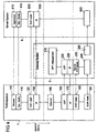
- FIG. 3 An alternative structure of the KPT extension is shown in FIG. The two horizontal dash-dot lines have the same meaning as in FIG. 3.
- TK End System 1 a module 196 emulating an Ethemet interface is provided.
- Known methods e.g., DHCP
- module 130 provides module 130 with an IP address in TK end system 1 when it is "logged in” to the Internet. This was done in the embodiment of FIG. 3 by the local PPP server 140.
- LAN local area network
- WLAN wireless local area network
- the degradation as well as the establishment of a KPT / PPP connection can be initiated both by the gateway 5 and by the TC end system 1.
- FIG. 3 Another alternative structure of the KPT extension is shown in FIG.
- the two horizontal dash-dot lines have the same meaning as in FIGS. 3 and 4.
- HDLC refers to a Level 2 protocol of the OSI Reference Model that sends data as HDLC packets / frames.
- the module 196 with the emulated Ethemet interface signals to the overlying modules 130, 120, 115, 110 of the TK-end system 1 that data sent by them via its Ethernet adapter to a local area network (LAN) or to a "wireless" local area network (WLAN).
- LAN local area network
- WLAN wireless local area network
- Module 196 then sends the data to HDLC module 185 without any change.
- the further encapsulation of the data in UDP / IP modules made in FIG. 4 is omitted.
- an HDLC module is used in the embodiment of FIG. 5.
- the associated connection setup for the considered L2 connection can be done in the case of an ISDN end system 1, for example, by a CAPI 197 (Common Application Programming Interface) interface.
- the HDLC data packets are transmitted to the gateway system 5 by means of an ISDN card 190 or - in the reverse direction of the data transfer - received by the latter.
- an ISDN card 190 or - in the reverse direction of the data transfer - received by the latter.
- the gateway system 5 there is a corresponding HDLC module 235 that undoes the HDLC packaging.
- FIG. 2 shows a second TK scenario of a communication process between a TC end system 1 and a server system 8. Identical objects as in FIG. 1 are identified by the same reference numerals.
- the TK scenario of FIG. 2 differs essentially in two aspects from the TK scenario of FIG. 1.
- a first difference is that the connection between the TK-end system 1 and the gateway 5 via a first telecommunications network 3 and a second telecommunications network 10 takes place, which are interconnected via an interconnect (ICA) 11. Accordingly, it is provided that the data sent by the TK-Endsystem 1 to the exchange 2 of this data via an ICA 11 to a second telecommunications network 10 are given. In this, the data is then transmitted to the gateway 5.
- ICA interconnect
- the first telecommunications network 3 is that of the former monopolist, that is, in Germany, the GermanInstitut AG (DTAG), which provides the local area network access.
- DTAG GermanInstitut AG
- ISP Internet Service Provider
- a so-called interconnect fee which is usually collected time-dependent. For example, a charge is calculated for each second that a data channel from the TK-end system 1 to the second TK network 10 is turned on.
- a so-called least-cost router (LCR) 12 can be provided between the telecommunications terminal 1 and the switching center 2, which specifies a specific second telecommunications network on the basis of specific criteria, in particular price criteria.
- the least-cost router 12 is optional - alternatively, the Users of the TK-Endsystems 1, the second TK network by dynamic "call by call", that is, using a specific area code at each connection, or by static "preselection" for all its connections select.
- a second difference of the embodiment of FIG. 2 compared to the embodiment of FIG. 1 is that the return channel from the server system 8 to the TK-end system 1 does not have to be realized via the packet-switched network 6 and the two TK-networks 3 and 10, but can be realized via another telecommunications network, which is a satellite network 14 in the illustrated embodiment.
- the data to be downloaded from the server system 8 to the TK-Endsystem 1 (downstream data) are transmitted here over the further TK network directly to the TK-Endsystem 1.
- Such a procedure is detailed in the EP 0 998 093 A2 described, to which reference is made.
- the data transmission between the TK-end system 1 and the server system 8 takes place asymmetrically insofar as only the upstream data via at least one telecommunications network 3, 10 and then the TK-packet switching network 6 (the Internet ), while the downstream data are transmitted back to the TK end system 1 via another TK network, namely a satellite network.
- the downstream data to be downloaded are only partially transmitted from the server system 8 via the satellite network to the TK-Endsystem 1.
- part of the data is transmitted via the Internet 6 and at least one of the TK networks 10, 3 to the TK end system 1. This makes it possible to use available bandwidth over the Internet and the PSTN / ISDN connection anyway.
- the server system 8 can be a proxy server which receives data to be transmitted by further servers 9 to the TC end system.
- data to be transmitted to the TK end system 1 is collected at the server system 8 before being transmitted to the TK end system 1.
- the server system 8 For example, in the case of an http application, firstly a www page is completely set up at the server system 8, wherein as a rule several TCP connections to other servers are established and associated data is fetched from there via it have to. After the complete set up of the www page requested by the TK end system at the server system 8, all associated data is transmitted jointly to the TK end system.
- the advantage is that the TK-Endsystem 1 must send only once confirmation packets concerning the reception of the data.
- a physical connection between the TK-Endsystem 1 and the gateway 5 according to the "coupling-pulse technique" described here must therefore be established only once for a short time to confirm the receipt of the www-page (and not for each component of the www- Page, ie for each of their TCP connections separately), so that there is a further cost savings.
- the acknowledgment packets are collected at the TC end system until a predetermined amount of data is available. In this variant, however, there may be delays in the return of the confirmation packets.
- the invention is not limited in its embodiment to the embodiments shown above.
- other access networks between the TK-Endsystem 1 and the gateway 5 can be realized, such as a GSM mobile network.
- the broadband return channel can be realized in other ways, for example via a Femsehtiv or a power cable.
Landscapes
- Engineering & Computer Science (AREA)
- Computer Networks & Wireless Communication (AREA)
- Signal Processing (AREA)
- Computer Security & Cryptography (AREA)
- Communication Control (AREA)
- Data Exchanges In Wide-Area Networks (AREA)
- Selective Calling Equipment (AREA)
- Exchange Systems With Centralized Control (AREA)
- Inspection Of Paper Currency And Valuable Securities (AREA)
Applications Claiming Priority (11)
| Application Number | Priority Date | Filing Date | Title |
|---|---|---|---|
| DE10256393 | 2002-12-02 | ||
| DE10256393 | 2002-12-02 | ||
| DE10257157 | 2002-12-02 | ||
| DE10257157 | 2002-12-02 | ||
| DE10316737 | 2003-04-04 | ||
| DE10316737 | 2003-04-04 | ||
| DE10321258 | 2003-05-06 | ||
| DE10321258 | 2003-05-06 | ||
| DE10338993 | 2003-08-18 | ||
| DE10338993 | 2003-08-18 | ||
| PCT/DE2003/004002 WO2004051924A2 (de) | 2002-12-02 | 2003-12-02 | Verfahren, telekommunikationsanordnung und tk-system zur steuerung der datenübertragung zwischen einem ersten und einem zweiten tk-system |
Publications (2)
| Publication Number | Publication Date |
|---|---|
| EP1568176A2 EP1568176A2 (de) | 2005-08-31 |
| EP1568176B1 true EP1568176B1 (de) | 2007-07-11 |
Family
ID=32475750
Family Applications (1)
| Application Number | Title | Priority Date | Filing Date |
|---|---|---|---|
| EP03782125A Expired - Lifetime EP1568176B1 (de) | 2002-12-02 | 2003-12-02 | Verfahren der Datenübertragung zwischen einem ersten und einem zweiten Telekommunikationssystem, Telekommunikationsanordnung und Telekommunikations-Endsystem zur Durchführung des Verfahrens |
Country Status (9)
| Country | Link |
|---|---|
| EP (1) | EP1568176B1 (pl) |
| AT (1) | ATE367028T1 (pl) |
| AU (1) | AU2003289819A1 (pl) |
| DE (2) | DE50307667D1 (pl) |
| DK (1) | DK1568176T3 (pl) |
| ES (1) | ES2290525T3 (pl) |
| NO (1) | NO20053196L (pl) |
| PL (1) | PL375635A1 (pl) |
| WO (1) | WO2004051924A2 (pl) |
Family Cites Families (4)
| Publication number | Priority date | Publication date | Assignee | Title |
|---|---|---|---|---|
| CA2107047C (en) * | 1992-12-29 | 1998-04-28 | Alan M. Bentley | Switched circuit connection management over public data networks for wide area networks |
| DE19700357C2 (de) * | 1996-12-10 | 2003-07-31 | Siemens Ag | Verfahren zur Anbindung eines Kommunikationsendgerätes an ein Datennetz |
| GB9925101D0 (en) * | 1999-10-22 | 1999-12-22 | Virtual Access Ireland Limited | Multi channel communication control system and method |
| NO20006127L (no) * | 2000-12-01 | 2002-06-03 | Ericsson Telefon Ab L M | Fremgangsmåte og arrangement for å tilveiebringe en virtuelt kontinuerlig forbindelse |
-
2003
- 2003-12-02 DE DE50307667T patent/DE50307667D1/de not_active Expired - Lifetime
- 2003-12-02 DE DE10393823T patent/DE10393823D2/de not_active Expired - Fee Related
- 2003-12-02 PL PL03375635A patent/PL375635A1/pl unknown
- 2003-12-02 EP EP03782125A patent/EP1568176B1/de not_active Expired - Lifetime
- 2003-12-02 AU AU2003289819A patent/AU2003289819A1/en not_active Abandoned
- 2003-12-02 ES ES03782125T patent/ES2290525T3/es not_active Expired - Lifetime
- 2003-12-02 WO PCT/DE2003/004002 patent/WO2004051924A2/de not_active Ceased
- 2003-12-02 DK DK03782125T patent/DK1568176T3/da active
- 2003-12-02 AT AT03782125T patent/ATE367028T1/de not_active IP Right Cessation
-
2005
- 2005-06-30 NO NO20053196A patent/NO20053196L/no not_active Application Discontinuation
Non-Patent Citations (1)
| Title |
|---|
| None * |
Also Published As
| Publication number | Publication date |
|---|---|
| WO2004051924A2 (de) | 2004-06-17 |
| DE10393823D2 (de) | 2005-08-18 |
| EP1568176A2 (de) | 2005-08-31 |
| NO20053196D0 (no) | 2005-06-30 |
| AU2003289819A8 (en) | 2004-06-23 |
| PL375635A1 (pl) | 2005-12-12 |
| WO2004051924A3 (de) | 2004-08-05 |
| ATE367028T1 (de) | 2007-08-15 |
| ES2290525T3 (es) | 2008-02-16 |
| AU2003289819A1 (en) | 2004-06-23 |
| DK1568176T3 (da) | 2007-11-12 |
| NO20053196L (no) | 2005-06-30 |
| DE50307667D1 (de) | 2007-08-23 |
Similar Documents
| Publication | Publication Date | Title |
|---|---|---|
| DE69933557T2 (de) | Vereinbarkeit von einem intelligenten netz und einem datenpaketnetz | |
| DE60311079T2 (de) | Digitales Teilnehmernanschlussleitungszugangsnetz mit verbesserter Authentifizierungs-, Berechtigungs-, Abrechnungs- und Konfigurationssteuerung für Multicast-Dienste | |
| DE69934734T2 (de) | Mehrstrecken Punkt-zu-Punkt Protokoll | |
| DE19645368C2 (de) | Verfahren und Kommunikationseinrichtung zur Übertragung von Daten in einem Telekommunikationsnetz | |
| DE69829346T2 (de) | Ein-/Ausgabevorrichtung für ein Peripheriegerät | |
| EP2191613B1 (de) | Verfahren zum benutzerspezifischen konfigurieren eines kommunikationsports | |
| DE4438522C2 (de) | Einrichtung zur Übertragung von Datenströmen in Datenkommunikationsnetzen | |
| DE10048487A1 (de) | Verfahren zum Anschluß von Datenendeinrichtungen an ein Datennetz | |
| DE60033283T2 (de) | Verfahren und systeme zur mitteilung von ss7-nachrichten über ein paketbasiertes netz unter verwendung einer transportanpassungsschichtschnittstelle | |
| DE69736925T2 (de) | Mobile Übertragungsvorrichtung, mobiles Datenübertragungsverfahren und Aufnahmemedium | |
| WO2004051924A2 (de) | Verfahren, telekommunikationsanordnung und tk-system zur steuerung der datenübertragung zwischen einem ersten und einem zweiten tk-system | |
| EP1665727B1 (de) | Verfahren zum vermitteln von informationen | |
| DE60314255T2 (de) | Signalisierung einer trägerverbindung in einer verteilten architektur | |
| DE60037210T2 (de) | Datenumwandlungs- und Kommunikationsverfahren | |
| EP4040721B1 (de) | Verfahren zum bereitstellen einer datenverbindung zum internet an einem telekommunikations-endgerät sowie serversystem | |
| DE10237131A1 (de) | Verfahren sowie Vorrichtung zur datenquellenspezifischen Kennzeichnung von Push-Nutzdaten | |
| EP1258110A2 (de) | Verfahren zur bidirektionalen datenübertragung über eine paketorientierte netzwerkeinrichtung | |
| EP1437011B1 (de) | Verfahren zur durchführung von augenblicklichem nachrichtenverkehr (instant messaging) mit paketvermittelten daten | |
| EP0998093B1 (de) | Verfahren zur Übertragung von Rückkanal-Daten in einer Verbindung zwischen einem Endgerät und einem Server eines Paketvermittlungsnetzes | |
| EP1559241B1 (de) | Verfahren und vorrichtung zum austausch von daten mittels einer tunnelverbindung | |
| DE19700357C2 (de) | Verfahren zur Anbindung eines Kommunikationsendgerätes an ein Datennetz | |
| EP1537719B1 (de) | Aktualisiering von auf einem rechner eines datenkommunikationssystems gespeicherter software | |
| DE102004021698B4 (de) | Verfahren und Telekommunikationsanordnung zur Steuerung der Auslastung von Einwählpunkten in ein Paketvermittlungsnetz | |
| DE10126709B4 (de) | Verfahren zur Verringerung der Latenzzeit bei der Übertragung von Informationen in einem GPRS-Netzwerk | |
| EP1847109B1 (de) | Verfahren zur steuerung eines gateways mittels eines dazwischenliegenden protokolls und gateway zur durchführung des verfahrens |
Legal Events
| Date | Code | Title | Description |
|---|---|---|---|
| PUAI | Public reference made under article 153(3) epc to a published international application that has entered the european phase |
Free format text: ORIGINAL CODE: 0009012 |
|
| 17P | Request for examination filed |
Effective date: 20050614 |
|
| AK | Designated contracting states |
Kind code of ref document: A2 Designated state(s): AT BE BG CH CY CZ DE DK EE ES FI FR GB GR HU IE IT LI LU MC NL PT RO SE SI SK TR |
|
| AX | Request for extension of the european patent |
Extension state: AL LT LV MK |
|
| DAX | Request for extension of the european patent (deleted) | ||
| RTI1 | Title (correction) |
Free format text: METHOD FOR TRANSMITTING DATA BETWEEN A FIRST AND A SECOND TELECOMMUNICATIONS SYSTEM, TELECOMMUNICATIONS ARRANGEMENT AND TELECOMMUNICATIONS END SYSTEM FOR CARRYING OUT THE METHOD |
|
| GRAP | Despatch of communication of intention to grant a patent |
Free format text: ORIGINAL CODE: EPIDOSNIGR1 |
|
| GRAS | Grant fee paid |
Free format text: ORIGINAL CODE: EPIDOSNIGR3 |
|
| GRAA | (expected) grant |
Free format text: ORIGINAL CODE: 0009210 |
|
| AK | Designated contracting states |
Kind code of ref document: B1 Designated state(s): AT BE BG CH CY CZ DE DK EE ES FI FR GB GR HU IE IT LI LU MC NL PT RO SE SI SK TR |
|
| REG | Reference to a national code |
Ref country code: GB Ref legal event code: FG4D Free format text: NOT ENGLISH |
|
| REG | Reference to a national code |
Ref country code: CH Ref legal event code: EP |
|
| REF | Corresponds to: |
Ref document number: 50307667 Country of ref document: DE Date of ref document: 20070823 Kind code of ref document: P |
|
| REG | Reference to a national code |
Ref country code: IE Ref legal event code: FG4D Free format text: LANGUAGE OF EP DOCUMENT: GERMAN |
|
| REG | Reference to a national code |
Ref country code: SE Ref legal event code: TRGR |
|
| REG | Reference to a national code |
Ref country code: CH Ref legal event code: NV Representative=s name: SCHMAUDER & PARTNER AG PATENTANWALTSBUERO |
|
| GBT | Gb: translation of ep patent filed (gb section 77(6)(a)/1977) |
Effective date: 20071016 |
|
| REG | Reference to a national code |
Ref country code: DK Ref legal event code: T3 |
|
| ET | Fr: translation filed | ||
| PG25 | Lapsed in a contracting state [announced via postgrant information from national office to epo] |
Ref country code: PT Free format text: LAPSE BECAUSE OF FAILURE TO SUBMIT A TRANSLATION OF THE DESCRIPTION OR TO PAY THE FEE WITHIN THE PRESCRIBED TIME-LIMIT Effective date: 20071211 Ref country code: BG Free format text: LAPSE BECAUSE OF FAILURE TO SUBMIT A TRANSLATION OF THE DESCRIPTION OR TO PAY THE FEE WITHIN THE PRESCRIBED TIME-LIMIT Effective date: 20071011 |
|
| PGFP | Annual fee paid to national office [announced via postgrant information from national office to epo] |
Ref country code: DK Payment date: 20071220 Year of fee payment: 5 Ref country code: LU Payment date: 20071219 Year of fee payment: 5 Ref country code: NL Payment date: 20071213 Year of fee payment: 5 |
|
| REG | Reference to a national code |
Ref country code: ES Ref legal event code: FG2A Ref document number: 2290525 Country of ref document: ES Kind code of ref document: T3 |
|
| PGFP | Annual fee paid to national office [announced via postgrant information from national office to epo] |
Ref country code: AT Payment date: 20071220 Year of fee payment: 5 Ref country code: CH Payment date: 20071219 Year of fee payment: 5 Ref country code: FI Payment date: 20071217 Year of fee payment: 5 |
|
| REG | Reference to a national code |
Ref country code: IE Ref legal event code: FD4D |
|
| PGFP | Annual fee paid to national office [announced via postgrant information from national office to epo] |
Ref country code: SE Payment date: 20071220 Year of fee payment: 5 Ref country code: BE Payment date: 20071219 Year of fee payment: 5 |
|
| PG25 | Lapsed in a contracting state [announced via postgrant information from national office to epo] |
Ref country code: GR Free format text: LAPSE BECAUSE OF FAILURE TO SUBMIT A TRANSLATION OF THE DESCRIPTION OR TO PAY THE FEE WITHIN THE PRESCRIBED TIME-LIMIT Effective date: 20071012 |
|
| PLBE | No opposition filed within time limit |
Free format text: ORIGINAL CODE: 0009261 |
|
| STAA | Information on the status of an ep patent application or granted ep patent |
Free format text: STATUS: NO OPPOSITION FILED WITHIN TIME LIMIT |
|
| PG25 | Lapsed in a contracting state [announced via postgrant information from national office to epo] |
Ref country code: SK Free format text: LAPSE BECAUSE OF FAILURE TO SUBMIT A TRANSLATION OF THE DESCRIPTION OR TO PAY THE FEE WITHIN THE PRESCRIBED TIME-LIMIT Effective date: 20070711 Ref country code: IE Free format text: LAPSE BECAUSE OF FAILURE TO SUBMIT A TRANSLATION OF THE DESCRIPTION OR TO PAY THE FEE WITHIN THE PRESCRIBED TIME-LIMIT Effective date: 20070711 Ref country code: CZ Free format text: LAPSE BECAUSE OF FAILURE TO SUBMIT A TRANSLATION OF THE DESCRIPTION OR TO PAY THE FEE WITHIN THE PRESCRIBED TIME-LIMIT Effective date: 20070711 |
|
| 26N | No opposition filed |
Effective date: 20080414 |
|
| PG25 | Lapsed in a contracting state [announced via postgrant information from national office to epo] |
Ref country code: RO Free format text: LAPSE BECAUSE OF FAILURE TO SUBMIT A TRANSLATION OF THE DESCRIPTION OR TO PAY THE FEE WITHIN THE PRESCRIBED TIME-LIMIT Effective date: 20070711 |
|
| PG25 | Lapsed in a contracting state [announced via postgrant information from national office to epo] |
Ref country code: MC Free format text: LAPSE BECAUSE OF NON-PAYMENT OF DUE FEES Effective date: 20071231 |
|
| PG25 | Lapsed in a contracting state [announced via postgrant information from national office to epo] |
Ref country code: EE Free format text: LAPSE BECAUSE OF FAILURE TO SUBMIT A TRANSLATION OF THE DESCRIPTION OR TO PAY THE FEE WITHIN THE PRESCRIBED TIME-LIMIT Effective date: 20070711 |
|
| BERE | Be: lapsed |
Owner name: TELES A.G. INFORMATIONSTECHNOLOGIEN Effective date: 20081231 |
|
| PG25 | Lapsed in a contracting state [announced via postgrant information from national office to epo] |
Ref country code: SI Free format text: LAPSE BECAUSE OF FAILURE TO SUBMIT A TRANSLATION OF THE DESCRIPTION OR TO PAY THE FEE WITHIN THE PRESCRIBED TIME-LIMIT Effective date: 20070711 |
|
| PG25 | Lapsed in a contracting state [announced via postgrant information from national office to epo] |
Ref country code: CY Free format text: LAPSE BECAUSE OF FAILURE TO SUBMIT A TRANSLATION OF THE DESCRIPTION OR TO PAY THE FEE WITHIN THE PRESCRIBED TIME-LIMIT Effective date: 20070711 Ref country code: FI Free format text: LAPSE BECAUSE OF NON-PAYMENT OF DUE FEES Effective date: 20081202 |
|
| REG | Reference to a national code |
Ref country code: CH Ref legal event code: PL |
|
| REG | Reference to a national code |
Ref country code: DK Ref legal event code: EBP |
|
| EUG | Se: european patent has lapsed | ||
| PG25 | Lapsed in a contracting state [announced via postgrant information from national office to epo] |
Ref country code: AT Free format text: LAPSE BECAUSE OF NON-PAYMENT OF DUE FEES Effective date: 20081202 |
|
| NLV4 | Nl: lapsed or anulled due to non-payment of the annual fee |
Effective date: 20090701 |
|
| PG25 | Lapsed in a contracting state [announced via postgrant information from national office to epo] |
Ref country code: TR Free format text: LAPSE BECAUSE OF FAILURE TO SUBMIT A TRANSLATION OF THE DESCRIPTION OR TO PAY THE FEE WITHIN THE PRESCRIBED TIME-LIMIT Effective date: 20070711 Ref country code: HU Free format text: LAPSE BECAUSE OF FAILURE TO SUBMIT A TRANSLATION OF THE DESCRIPTION OR TO PAY THE FEE WITHIN THE PRESCRIBED TIME-LIMIT Effective date: 20080112 Ref country code: BE Free format text: LAPSE BECAUSE OF NON-PAYMENT OF DUE FEES Effective date: 20081231 |
|
| PG25 | Lapsed in a contracting state [announced via postgrant information from national office to epo] |
Ref country code: CH Free format text: LAPSE BECAUSE OF NON-PAYMENT OF DUE FEES Effective date: 20081231 Ref country code: LI Free format text: LAPSE BECAUSE OF NON-PAYMENT OF DUE FEES Effective date: 20081231 |
|
| PG25 | Lapsed in a contracting state [announced via postgrant information from national office to epo] |
Ref country code: NL Free format text: LAPSE BECAUSE OF NON-PAYMENT OF DUE FEES Effective date: 20090701 |
|
| PG25 | Lapsed in a contracting state [announced via postgrant information from national office to epo] |
Ref country code: DK Free format text: LAPSE BECAUSE OF NON-PAYMENT OF DUE FEES Effective date: 20090105 |
|
| REG | Reference to a national code |
Ref country code: GB Ref legal event code: 732E Free format text: REGISTERED BETWEEN 20100225 AND 20100303 |
|
| REG | Reference to a national code |
Ref country code: FR Ref legal event code: TP |
|
| REG | Reference to a national code |
Ref country code: ES Ref legal event code: PC2A |
|
| PG25 | Lapsed in a contracting state [announced via postgrant information from national office to epo] |
Ref country code: SE Free format text: LAPSE BECAUSE OF NON-PAYMENT OF DUE FEES Effective date: 20081203 Ref country code: LU Free format text: LAPSE BECAUSE OF NON-PAYMENT OF DUE FEES Effective date: 20081202 |
|
| PGFP | Annual fee paid to national office [announced via postgrant information from national office to epo] |
Ref country code: GB Payment date: 20101221 Year of fee payment: 8 |
|
| PGFP | Annual fee paid to national office [announced via postgrant information from national office to epo] |
Ref country code: IT Payment date: 20101228 Year of fee payment: 8 |
|
| PGFP | Annual fee paid to national office [announced via postgrant information from national office to epo] |
Ref country code: ES Payment date: 20111219 Year of fee payment: 9 Ref country code: FR Payment date: 20120103 Year of fee payment: 9 |
|
| GBPC | Gb: european patent ceased through non-payment of renewal fee |
Effective date: 20121202 |
|
| REG | Reference to a national code |
Ref country code: FR Ref legal event code: ST Effective date: 20130830 |
|
| PG25 | Lapsed in a contracting state [announced via postgrant information from national office to epo] |
Ref country code: GB Free format text: LAPSE BECAUSE OF NON-PAYMENT OF DUE FEES Effective date: 20121202 Ref country code: FR Free format text: LAPSE BECAUSE OF NON-PAYMENT OF DUE FEES Effective date: 20130102 |
|
| PG25 | Lapsed in a contracting state [announced via postgrant information from national office to epo] |
Ref country code: IT Free format text: LAPSE BECAUSE OF NON-PAYMENT OF DUE FEES Effective date: 20121202 |
|
| REG | Reference to a national code |
Ref country code: ES Ref legal event code: FD2A Effective date: 20140306 |
|
| PG25 | Lapsed in a contracting state [announced via postgrant information from national office to epo] |
Ref country code: ES Free format text: LAPSE BECAUSE OF NON-PAYMENT OF DUE FEES Effective date: 20121203 |
|
| REG | Reference to a national code |
Ref country code: DE Ref legal event code: R082 Ref document number: 50307667 Country of ref document: DE Representative=s name: ADARES PATENT- UND RECHTSANWAELTE REININGER & , DE |
|
| REG | Reference to a national code |
Ref country code: DE Ref legal event code: R082 Ref document number: 50307667 Country of ref document: DE Representative=s name: ADARES PATENT- UND RECHTSANWAELTE REININGER & , DE Ref country code: DE Ref legal event code: R082 Ref document number: 50307667 Country of ref document: DE |
|
| REG | Reference to a national code |
Ref country code: DE Ref legal event code: R082 Ref document number: 50307667 Country of ref document: DE |
|
| PGFP | Annual fee paid to national office [announced via postgrant information from national office to epo] |
Ref country code: DE Payment date: 20230620 Year of fee payment: 20 |
|
| REG | Reference to a national code |
Ref country code: DE Ref legal event code: R071 Ref document number: 50307667 Country of ref document: DE |