EP1568108B1 - Battery connector - Google Patents
Battery connector Download PDFInfo
- Publication number
- EP1568108B1 EP1568108B1 EP03778181A EP03778181A EP1568108B1 EP 1568108 B1 EP1568108 B1 EP 1568108B1 EP 03778181 A EP03778181 A EP 03778181A EP 03778181 A EP03778181 A EP 03778181A EP 1568108 B1 EP1568108 B1 EP 1568108B1
- Authority
- EP
- European Patent Office
- Prior art keywords
- battery
- circuit board
- contacting arm
- contact
- contacting
- Prior art date
- Legal status (The legal status is an assumption and is not a legal conclusion. Google has not performed a legal analysis and makes no representation as to the accuracy of the status listed.)
- Expired - Lifetime
Links
- 239000000463 material Substances 0.000 claims description 6
- 239000011295 pitch Substances 0.000 description 18
- PXHVJJICTQNCMI-UHFFFAOYSA-N Nickel Chemical compound [Ni] PXHVJJICTQNCMI-UHFFFAOYSA-N 0.000 description 4
- 238000009434 installation Methods 0.000 description 3
- 238000007747 plating Methods 0.000 description 3
- DMFGNRRURHSENX-UHFFFAOYSA-N beryllium copper Chemical compound [Be].[Cu] DMFGNRRURHSENX-UHFFFAOYSA-N 0.000 description 2
- 239000002184 metal Substances 0.000 description 2
- 229910052751 metal Inorganic materials 0.000 description 2
- 229910052759 nickel Inorganic materials 0.000 description 2
- 238000005476 soldering Methods 0.000 description 2
- 230000004075 alteration Effects 0.000 description 1
- 230000008901 benefit Effects 0.000 description 1
- 230000005540 biological transmission Effects 0.000 description 1
- 238000005266 casting Methods 0.000 description 1
- 230000001413 cellular effect Effects 0.000 description 1
- 230000008859 change Effects 0.000 description 1
- 230000001419 dependent effect Effects 0.000 description 1
- 230000000694 effects Effects 0.000 description 1
- 239000011521 glass Substances 0.000 description 1
- PCHJSUWPFVWCPO-UHFFFAOYSA-N gold Chemical compound [Au] PCHJSUWPFVWCPO-UHFFFAOYSA-N 0.000 description 1
- 239000010931 gold Substances 0.000 description 1
- 229910052737 gold Inorganic materials 0.000 description 1
- 238000004519 manufacturing process Methods 0.000 description 1
- 230000013011 mating Effects 0.000 description 1
- 238000000034 method Methods 0.000 description 1
- 230000004048 modification Effects 0.000 description 1
- 238000012986 modification Methods 0.000 description 1
- 239000004033 plastic Substances 0.000 description 1
- 230000036316 preload Effects 0.000 description 1
- 230000008569 process Effects 0.000 description 1
- 239000007787 solid Substances 0.000 description 1
- 238000003860 storage Methods 0.000 description 1
- 229920001169 thermoplastic Polymers 0.000 description 1
- 239000004416 thermosoftening plastic Substances 0.000 description 1
- 238000003466 welding Methods 0.000 description 1
Images


Classifications
-
- H—ELECTRICITY
- H01—ELECTRIC ELEMENTS
- H01R—ELECTRICALLY-CONDUCTIVE CONNECTIONS; STRUCTURAL ASSOCIATIONS OF A PLURALITY OF MUTUALLY-INSULATED ELECTRICAL CONNECTING ELEMENTS; COUPLING DEVICES; CURRENT COLLECTORS
- H01R13/00—Details of coupling devices of the kinds covered by groups H01R12/70 or H01R24/00 - H01R33/00
- H01R13/02—Contact members
- H01R13/22—Contacts for co-operating by abutting
- H01R13/24—Contacts for co-operating by abutting resilient; resiliently-mounted
- H01R13/2407—Contacts for co-operating by abutting resilient; resiliently-mounted characterized by the resilient means
-
- H—ELECTRICITY
- H01—ELECTRIC ELEMENTS
- H01R—ELECTRICALLY-CONDUCTIVE CONNECTIONS; STRUCTURAL ASSOCIATIONS OF A PLURALITY OF MUTUALLY-INSULATED ELECTRICAL CONNECTING ELEMENTS; COUPLING DEVICES; CURRENT COLLECTORS
- H01R11/00—Individual connecting elements providing two or more spaced connecting locations for conductive members which are, or may be, thereby interconnected, e.g. end pieces for wires or cables supported by the wire or cable and having means for facilitating electrical connection to some other wire, terminal, or conductive member, blocks of binding posts
- H01R11/11—End pieces or tapping pieces for wires, supported by the wire and for facilitating electrical connection to some other wire, terminal or conductive member
- H01R11/28—End pieces consisting of a ferrule or sleeve
- H01R11/281—End pieces consisting of a ferrule or sleeve for connections to batteries
- H01R11/282—End pieces consisting of a ferrule or sleeve for connections to batteries comprising means for facilitating engagement or disengagement, e.g. quick release terminal
-
- H—ELECTRICITY
- H01—ELECTRIC ELEMENTS
- H01R—ELECTRICALLY-CONDUCTIVE CONNECTIONS; STRUCTURAL ASSOCIATIONS OF A PLURALITY OF MUTUALLY-INSULATED ELECTRICAL CONNECTING ELEMENTS; COUPLING DEVICES; CURRENT COLLECTORS
- H01R12/00—Structural associations of a plurality of mutually-insulated electrical connecting elements, specially adapted for printed circuits, e.g. printed circuit boards [PCB], flat or ribbon cables, or like generally planar structures, e.g. terminal strips, terminal blocks; Coupling devices specially adapted for printed circuits, flat or ribbon cables, or like generally planar structures; Terminals specially adapted for contact with, or insertion into, printed circuits, flat or ribbon cables, or like generally planar structures
- H01R12/50—Fixed connections
- H01R12/51—Fixed connections for rigid printed circuits or like structures
- H01R12/52—Fixed connections for rigid printed circuits or like structures connecting to other rigid printed circuits or like structures
-
- H—ELECTRICITY
- H01—ELECTRIC ELEMENTS
- H01R—ELECTRICALLY-CONDUCTIVE CONNECTIONS; STRUCTURAL ASSOCIATIONS OF A PLURALITY OF MUTUALLY-INSULATED ELECTRICAL CONNECTING ELEMENTS; COUPLING DEVICES; CURRENT COLLECTORS
- H01R12/00—Structural associations of a plurality of mutually-insulated electrical connecting elements, specially adapted for printed circuits, e.g. printed circuit boards [PCB], flat or ribbon cables, or like generally planar structures, e.g. terminal strips, terminal blocks; Coupling devices specially adapted for printed circuits, flat or ribbon cables, or like generally planar structures; Terminals specially adapted for contact with, or insertion into, printed circuits, flat or ribbon cables, or like generally planar structures
- H01R12/70—Coupling devices
- H01R12/71—Coupling devices for rigid printing circuits or like structures
- H01R12/712—Coupling devices for rigid printing circuits or like structures co-operating with the surface of the printed circuit or with a coupling device exclusively provided on the surface of the printed circuit
- H01R12/714—Coupling devices for rigid printing circuits or like structures co-operating with the surface of the printed circuit or with a coupling device exclusively provided on the surface of the printed circuit with contacts abutting directly the printed circuit; Button contacts therefore provided on the printed circuit
-
- H—ELECTRICITY
- H01—ELECTRIC ELEMENTS
- H01R—ELECTRICALLY-CONDUCTIVE CONNECTIONS; STRUCTURAL ASSOCIATIONS OF A PLURALITY OF MUTUALLY-INSULATED ELECTRICAL CONNECTING ELEMENTS; COUPLING DEVICES; CURRENT COLLECTORS
- H01R13/00—Details of coupling devices of the kinds covered by groups H01R12/70 or H01R24/00 - H01R33/00
- H01R13/02—Contact members
- H01R13/22—Contacts for co-operating by abutting
- H01R13/24—Contacts for co-operating by abutting resilient; resiliently-mounted
- H01R13/2435—Contacts for co-operating by abutting resilient; resiliently-mounted with opposite contact points, e.g. C beam
-
- H—ELECTRICITY
- H01—ELECTRIC ELEMENTS
- H01R—ELECTRICALLY-CONDUCTIVE CONNECTIONS; STRUCTURAL ASSOCIATIONS OF A PLURALITY OF MUTUALLY-INSULATED ELECTRICAL CONNECTING ELEMENTS; COUPLING DEVICES; CURRENT COLLECTORS
- H01R13/00—Details of coupling devices of the kinds covered by groups H01R12/70 or H01R24/00 - H01R33/00
- H01R13/02—Contact members
- H01R13/22—Contacts for co-operating by abutting
- H01R13/24—Contacts for co-operating by abutting resilient; resiliently-mounted
- H01R13/2442—Contacts for co-operating by abutting resilient; resiliently-mounted with a single cantilevered beam
-
- H—ELECTRICITY
- H01—ELECTRIC ELEMENTS
- H01R—ELECTRICALLY-CONDUCTIVE CONNECTIONS; STRUCTURAL ASSOCIATIONS OF A PLURALITY OF MUTUALLY-INSULATED ELECTRICAL CONNECTING ELEMENTS; COUPLING DEVICES; CURRENT COLLECTORS
- H01R13/00—Details of coupling devices of the kinds covered by groups H01R12/70 or H01R24/00 - H01R33/00
- H01R13/02—Contact members
- H01R13/22—Contacts for co-operating by abutting
- H01R13/24—Contacts for co-operating by abutting resilient; resiliently-mounted
-
- H—ELECTRICITY
- H01—ELECTRIC ELEMENTS
- H01R—ELECTRICALLY-CONDUCTIVE CONNECTIONS; STRUCTURAL ASSOCIATIONS OF A PLURALITY OF MUTUALLY-INSULATED ELECTRICAL CONNECTING ELEMENTS; COUPLING DEVICES; CURRENT COLLECTORS
- H01R2201/00—Connectors or connections adapted for particular applications
- H01R2201/16—Connectors or connections adapted for particular applications for telephony
Definitions
- the present invention relates in general to battery powered electronic devices and more specifically to a battery connector for such battery powered electronic devices.
- Such devices include, for example, wireless email devices, digital cameras, cellular telephones, and Personal Digital Assistants (PDA's).
- PDA's Personal Digital Assistants
- Such devices typically include a main circuit board for controlling the device's operations, and a battery for providing power to the circuit board.
- the battery is typically removable either for recharging or replacement.
- the secondary circuit board may provide control for optional features that are available on the device for an added cost.
- the secondary circuit board may be a purchased board that is provided by an outside supplier that has particular expertise in a particular technology used in the device.
- a first connector is provided on a first board for receiving power from the battery.
- a tracing on the first board leads from the first connector to a second connector, which connects the first board to the second board. Power is routed to the second board through this second connector.
- EP 0 939 457 A2 discloses a device to board electrical connector having terminal sections for connecting to a first circuit board, a second circuit board, and a battery pack, respectively.
- the first terminal section is configured for soldering to the first circuit board whilst the other two terminal sections have spring portions for resilently abutting respective contact protrusions adjacent the battery pack and the second circuit board.
- US 5,909,102 discloses a battery attachment apparatus for attaching a battery to an electronic device.
- the contact arrangement has a flat contact carried on the battery and a spring contact carried on the electronic device. Once assembled, the spring contact is in a fully-extended rest position.
- the present invention provides an apparatus having a battery and one or more power consuming circuit boards according to independent claim 1.
- the dependent claims relate to preferred embodiments.
- the battery connector 10 shown in Fig. 1 includes a plurality of electrical conduits 20 and a housing 22.
- the battery connector 10 may include four electrical conduits 20 as shown in the figures, or any other suitable number of conduits depending on the particular configuration of the battery 14 and first and second circuit boards 16 and 18.
- the term "electrical conduit” in this application refers to a continuous, electrically conducting structure capable of passing an electrical signal.
- Each electrical conduit 20 (as shown in greater detail in Figs. 2 and 3 ) includes a battery contacting arm 24, a first board contacting arm 26, a second board contacting arm 28, and a base 30.
- the battery contacting arm 24 includes a spring 32, a battery contact 34, and a hook 36.
- the spring 32 applies a mechanical contacting force between the battery contact 34 and a corresponding connector contact 38 ( Fig. 1 ) on the battery 14.
- the spring 32 is a resilient, U-shaped portion of the battery contacting arm 24, located between the battery contact 34 and the base 30.
- the battery contacting arm 24, and in particular the spring 32, has a width W b and a thickness T b , which permit the battery contacting arm 24 to be used for a selected number of battery replacements without failure due to fatigue.
- the number of battery replacements depends on the overall expected operating life of the device 12 as well as on other factors, such as the expected battery draw from the device and the storage capacity of the battery 14.
- the battery contact 34 is the portion of the battery contacting arm 24 that mechanically mates with a corresponding contact on the battery 14 to make an electrical connection therebetween.
- the battery contact 34 may be a boss on the battery contacting arm 24, which has a generally domed surface. The domed surface provides a consistent contact area, even in cases where there is some misalignment in the battery contacting arm 24, either torsionally, angularly or linearly.
- the battery contacting arm 24 contains a hook 36.
- the battery contacting arm 24 is shown in Fig. 2 in its rest position (dasheld outline), prior to installation in the housing 22. In this rest position, the spring 32 is unflexed.
- the hook 36 engages a hook retaining piece 40 on the housing 22 to maintain the battery contacting arm 24 in a pre-engagement position, shown in solid outline in Fig. 2 .
- the pre-engagement position of the arm 24 is the position of the arm 24 prior to engagement with the battery 14 (see Fig. 1 ). In the pre-engagement position, the spring 32 is flexed to some degree, and thus maintains the hook 36 in engagement with the hook retaining piece 40.
- the position of the battery contact 34 can be maintained with a greater degree of accuracy relative to a configuration in which there is no pre-load in the spring 32. This is because even if there is some manufacturing tolerance in the actual rest position of the arm 24, the arm 24 remains consistently positioned in the pre-engagement position. Any variance in the actual rest position of the arm 24 results in a greater or lesser degree of flex in the spring 32 when the arm is in the pre-engagement position. Providing a consistent positioning for the arm 24 in the pre-engagement position improves the alignment of one arm 24 with other arms 24 on other electrical conduits 20 on the battery connector 10. Consistent positioning allows for a greater assurance that the battery 14 and arms 24 engage when the battery 14 is installed in the device 12.
- the pre-loading of the arms 24 also provides another advantage.
- the battery 14 may be removed and re-installed many times, and as such, the battery contacting arms 24 may be subject to fatigue and the housing 22 may experience plastic deformation, whereby the rest positions of the electrical conduits may begin to creep.
- the arms 24 pre-loaded in the pre-engagement position their pre-engagement position will not change due to fatigue or other factors that can affect their rest position.
- the battery contacting arm 24 When the battery contacting arm 24 is engaged by the battery 14, it may be flexed by any suitable amount.
- the battery 14 may be positioned so that the contacts 38 abut the housing 22, so that in turn, the battery contacting arms 24 recede into the housing 22.
- the first board contacting arm 26 may includes a spring 42, as shown in Fig. 3 , and includes a first board contact 44.
- the spring 42 may be a generally curved portion of the first board contacting arm 26, between the first board contact 44 and the base 30.
- the width and thickness of the spring 42 are shown at W 1 and T 1 , respectively.
- the spring 42 is subject to a relatively smaller number of cycles of flexure and release, relative to spring 32 of the battery contacting arm 24, because the battery connector 10 remains installed in the device 12, in contact with the first and second boards 16 and 18 throughout most or all of the operating life of the device 12. Because of the relatively low number of expected cycles of flexure and release for the spring 42, one or both of the width W 1 and thickness T 1 may be selected to be smaller than the corresponding dimension of the battery contacting arm 24.
- the first board contact 44 mechanically mates with a corresponding contact 46 ( Fig. 1 ) on the first circuit board 16 to make an electrical connection therebetween, for the transmission of power from the battery 14 to the first circuit board 16.
- the first board contact 44 may be similar to the battery contact 34, and may be a generally domed surface on a boss on the first board contacting arm 26.
- the second board contacting arm 28 may be similar to the first board contacting arm 26, and may includes a spring 48 and includes a second board contact 50 for mechanically mating with a corresponding contact 51 on the second circuit board 18, which may be similar to the spring 42 and the first board contact 44, respectively.
- the spring 48 has a width W 2 and a thickness T 2 .
- the base 30 serves as a mounting point for contacting arms 24, 26 and 28, and includes means for mounting the electrical conduit 20 to the housing 22.
- the mounting means include wings 52 and a locking tab 54.
- the wings 52 engage corresponding blind slots 56 in the housing 22, as shown in Fig. 4a .
- the engagement of the wings 52 and the slots 56 assists in retaining the electrical conduits in the housing 22.
- a leading edge 58 of each wing 52 is chamfered to facilitate the movement of the wings 52 in the slots 56 during the installation of the electrical conduits 20 in the housing 22.
- the locking tab 54 engages a corresponding locking shoulder 60 ( Fig. 2 ) on the housing 22, to prevent the electrical conduit 20 from sliding backwards out of the slots 56, and thus, locks the electrical conduit 20 in place.
- the electrical connector 20 is preferably made from a single piece of material to reduce any resistive losses in the electrical path from the battery 14 to each of the first and second circuit boards 16 and 18. It is alternatively possible, however, that the electrical conduit 20 may be made from two or more pieces of material that are physically joined in an electrically conducting manner.
- the material of the electrical conduit 20 is preferably relatively electrically conductive, and may be Beryllium-Copper, and may include an optional Nickel plating over the Beryllium-Copper. Gold plating may be laid over the nickel plating. Alternatively, other materials may be used for the electrical conduit 20.
- the electrical conduit 20 may be manufactured from a sheet metal of a suitable thickness.
- the sheet metal may be stamped, and then the stamping may be bent as necessary, using any suitable means.
- Each compartment 62 includes retaining means for retaining an electrical conduit 20.
- the retaining means may be any suitable retaining means.
- the retaining means may include two blind slots 56 that slidably receive the wings 52 on the electrical conduit 20, as shown in Fig. 3 .
- the retaining means may further include the locking shoulder 60, which engages the locking tab 54 on the electrical conduit 20.
- a chamfered lead-in surface 64 is provided on the housing 22 to move the locking tab 54 on the electrical conduit 20 into a non-engaging position, when the electrical conduit 20 is being moved towards the end of its travel in the blind slots 56.
- the lead-in surface 64 is shown as being relatively close to the locking shoulder 60 so that the lead-in surface 64 acts on the locking tab 54 almost immediately prior to the locking tab 54 moving into its engaged position against the shoulder 60. It is alternatively possible, however, for the lead-in surface 64 to be positioned anywhere to engage the locking tab 54 and move the locking tab 54 to its non-engaged position prior to its engagement with the locking shoulder 60.
- Each compartment 62 further includes the hook retaining piece 40, for engaging the hook 36 on the battery contacting arm 24 of the electrical conduit 20.
- the housing 22 has a battery engagement face 66, from which the battery contacting arms 24 of the electrical conduit 20 protrude.
- the housing 22 includes one or more battery engagement shoulders 68 on the battery engagement face 66, to abut the battery 14 and to limit the flexure of the battery contacting arm 24 when the battery 14 is installed.
- the housing 22 includes a first board engagement face 70, from which the first board contacting arms 26 may protrude.
- the housing 22 includes one or more first board engagement shoulders 72, which abut the first circuit board 16 and which limit the flexure of the first board contacting arms 26.
- the housing 22 includes a second board engagement face 74, from which the second board contacting arms 28 may protrude.
- the housing 22 includes one or more second board engagement shoulders 76 which abut the second circuit board 18 and which limit the flexure of the second board contacting arms 28.
- the housing 22 may further include a means for mounting the housing 22 to the first and second circuit boards 16 and 18.
- the means may include a pair of mounting ribs 78, which may be received in corresponding slots that are either defined on one of the boards 16 or 18, or on a component, such as a structural casting, that is positionable between the boards 16 and 18.
- housing 22 mount to any other suitable component of the device 12 instead of mounting to the first and second circuit boards 16 and 18.
- the housing 22 physically separates the electrical conduits 20 from each other, and also serves to isolate them electrically from each other.
- the housing 22 is made from an electrically insulative material.
- the housing 22 may be made from a glass-filled thermoplastic.
- the electrical conduits 20 on the battery connector 10 have a center-to-center pitch P bc .
- the contacts 38 on the battery 14 have a center-to-center pitch P batt that at least in part determines the center-to-center pitch P bc .
- P batt that at least in part determines the center-to-center pitch P bc .
- a larger pitch P bc permits, for example, a large width W b of the spring 32 on the battery contacting arm 24, which, in turn, can improve the resistance of the arm 24 to fatigue.
- a larger pitch P bc permits the thickness of portions of the housing 22 to be larger, which permits the housing to have improved dimensional stability, and permits the housing to better insulate the electrical conduits 20 from each other.
- Electrical conduits 20 may be optionally positioned on a center-to-center pitch P bc that is larger than the center-to-center pitch P batt of the battery 14.
- the degree of increase that can be accommodated in the pitch P bc over the pitch P batt depends at least in part on the width of the battery contacts 34, and the width of the contacts 38 on the battery 14. It will be noted, however, that for each successive electrical conduit 20, the offset between the center of the battery contact 34 and the center of the contact 38 on the battery 14 increases.
- Permitting the pitch P bc of the electrical conduits 20 to be different than the pitch P batt of the contacts 38 on the battery 20 creates flexibility in battery choice.
- a different P bc pitch enables the battery connector 10 to be used with batteries 14 having different pitches P batt of contacts 38.
- a larger pitch P bc for the electrical conduits 20 relative to the pitch P batt allows the springs 32 on the battery contacting arms 24 to be wider, increasing the resistance to fatigue for the springs 32.
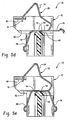
- Figs. 5a , 5b , 5c , 5d and 5e illustrate the assembly process for the electrical conduits 20 and the housing 22.
- the first board contacting arm 26 on each electrical conduit 20 may extend outwards, generally parallel to the base 30, as shown in Fig. 5a .
- the battery contacting arm 24 is in the rest position.
- the electrical conduits 20 may be installed in the housing 22 by sliding engagement of the wings 52 in the slots 56, as shown in Fig. 5b . Also shown in Fig. 5b , the battery contacting arm 24 is flexed at least to the pre-engagement position and preferably therepast, so that, as the electrical conduit 20 is moved along in the slots 56, the hook 36 can be positioned to engage the retaining piece 40 on the housing 22.
- the locking tab 54 is moved into a non-engaged position by the lead-in surface 64, as shown in Fig. 5c . Also shown in Fig. 5c is that as the electrical conduit 20 is moved along in the slots 56, the hook 36 is engaged by the hook retaining piece 40.
- the arm 26 may be bent by any suitable means so that it achieves the position shown in Fig. 5e , wherein it is ready for engagement with the first circuit board 16.
- the battery connector 80 may be similar to the battery connector 10 ( Fig. 1 ), and includes a plurality of electrical conduits 82 and a housing 84.
- the electrical conduits 82 may be similar to the electrical conduits 20 ( Fig. 1 ) and each includes a battery contacting arm 86, a first board contacting arm 88, a second board contacting arm 90 and a base 92.
- the battery contacting arm 86 may be similar to the battery contacting arm 24 ( Fig. 3 ), and includes a spring 94, a battery contact 96 and a hook 98.
- the first board contacting arm 88 may be similar to the first board contacting arm 26 ( Fig. 3 ), except that the first board contacting arm 88 is connected to the end of the second board contacting arm 90.
- the first board contacting arm 88 includes a spring 100 and has a first board contact 102.
- the spring 100 permits the first board contacting arm 88 to move relative to the second board contacting arm 90, and permits the exertion of a mechanical contact force between the first board contact 102 and the contact 46 on the first circuit board 16, as shown in Fig. 1 .
- the spring 100 is positioned between the first board contact 102 and the end of the second board contacting arm 90.
- the second board contacting arm 90 may be similar to the second board contacting arm 28, as shown in Fig. 3 , and includes a spring 104 and has a second board contact 106.
- the spring 104 is positioned between the second board contact 106 and the base 92 and permits the movement of the second board contact 106 relative to the base 92.
- the spring 104 also permits the exertion of a mechanical contacting force between the second board contact 106 and the contact 51 on the second circuit board 18, as shown in Fig. 1 .
- the base 92 may be similar to the base 30, and may include wings 108 and a locking tab 110, which may be similar to the wings 52 and the locking tab 54 respectively, as shown in Fig. 3 .
- the housing 84 may be similar to the housing 22 and may define a plurality of compartments 112, each of which retains an electrical conduit 82.
- Each compartment 112 may include a retaining piece 114 for engaging and retaining the hook 98, to retain the battery contacting arm 86 in the pre-engagement position.
- Each compartment 112 may further include two slots 116 and a locking shoulder 118 which may be similar to the slots 56 and the locking shoulder 60, as shown in Fig. 4b .
- the width of the battery contacting arm 86 may be increased, relative to the battery contacting arm 24, shown in Fig. 3 , while providing the electrical conduit 82 with a similar overall width as the electrical conduit 20. This permits the battery contacting arm 86 to be more resistant to fatigue than the arm 24 of the electrical conduit 20 shown in Fig. 3 .
- the electrical conduits 20 and 82 may not include a base 30 or 92, and instead to have arms that connect to each other directly.
- the means for mounting the electrical conduit 20 or 82 to the housing 22 or 84 may be positioned directly on one or more of the arms.
- the arms on the electrical conduits 20 and 82 have been described as having springs integrally formed thereon. It is optionally possible for the arms to incorporate separate springs that are not integrally formed thereon, which are connected between the contacts and the base 30 or 92.
- first and second board contacting arms 26 and 28, or 88 and 90 may be physically joined, for example, by soldering or welding, to the first or second circuit boards 16 and 18.
- the present invention is directed at a battery connector for battery powered electronic devices.
Landscapes
- Battery Mounting, Suspending (AREA)
- Dry Shavers And Clippers (AREA)
- Coupling Device And Connection With Printed Circuit (AREA)
Abstract
Description
- The present invention relates in general to battery powered electronic devices and more specifically to a battery connector for such battery powered electronic devices.
- Currently, there are many battery powered electronic devices on the market for a wide range of applications. Such devices include, for example, wireless email devices, digital cameras, cellular telephones, and Personal Digital Assistants (PDA's). Such devices typically include a main circuit board for controlling the device's operations, and a battery for providing power to the circuit board. The battery is typically removable either for recharging or replacement.
- Presently, some manufacturers have incorporated a secondary circuit board into their device, in effect splitting up control of the device onto two or more boards. The secondary circuit board may provide control for optional features that are available on the device for an added cost. Alternatively, the secondary circuit board may be a purchased board that is provided by an outside supplier that has particular expertise in a particular technology used in the device.
- Typically, in a device having two boards, a first connector is provided on a first board for receiving power from the battery. A tracing on the first board leads from the first connector to a second connector, which connects the first board to the second board. Power is routed to the second board through this second connector.
-
EP 0 939 457 A2 discloses a device to board electrical connector having terminal sections for connecting to a first circuit board, a second circuit board, and a battery pack, respectively. The first terminal section is configured for soldering to the first circuit board whilst the other two terminal sections have spring portions for resilently abutting respective contact protrusions adjacent the battery pack and the second circuit board. -
US 5,909,102 discloses a battery attachment apparatus for attaching a battery to an electronic device. The contact arrangement has a flat contact carried on the battery and a spring contact carried on the electronic device. Once assembled, the spring contact is in a fully-extended rest position. - The present invention provides an apparatus having a battery and one or more power consuming circuit boards according to
independent claim 1. The dependent claims relate to preferred embodiments. - Embodiments of the present invention will now be described, by way of example only, with reference to the attached Figures, wherein:
-
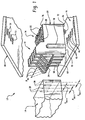
Fig. 1 is a perspective view of an exemplary battery connector. -
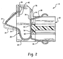
Fig. 2 is a sectional side view of the battery connector shown inFig. 1 . -
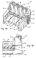
Fig. 3 is a perspective view of an electrical conduit that is part of the battery connector shown inFig. 1 . -
Fig. 4a is a perspective view of a housing that is part of the battery connector shown inFig. 1 . -
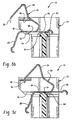
Fig. 4b is a sectional side view of the housing shown inFig. 4a . -
Figs. 5a ,5b ,5c ,5d and 5e are sectional side views that illustrate the assembly of the battery connector shown inFig. 1 . -
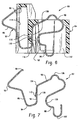
Fig. 6 is a sectional side view of another exemplary battery connector. -
Fig. 7 is a side view of an electrical conduitthat is part of the battery connector shown inFig. 6 . - The
battery connector 10 shown inFig. 1 includes a plurality ofelectrical conduits 20 and ahousing 22. Thebattery connector 10 may include fourelectrical conduits 20 as shown in the figures, or any other suitable number of conduits depending on the particular configuration of thebattery 14 and first andsecond circuit boards - Each electrical conduit 20 (as shown in greater detail in
Figs. 2 and3 ) includes abattery contacting arm 24, a firstboard contacting arm 26, a secondboard contacting arm 28, and abase 30. Referring specifically toFig. 3 , thebattery contacting arm 24 includes aspring 32, abattery contact 34, and ahook 36. When thebattery 14 is installed in thedevice 12, thespring 32 applies a mechanical contacting force between thebattery contact 34 and a corresponding connector contact 38 (Fig. 1 ) on thebattery 14. Thespring 32 is a resilient, U-shaped portion of thebattery contacting arm 24, located between thebattery contact 34 and thebase 30. - The
battery contacting arm 24, and in particular thespring 32, has a width Wb and a thickness Tb, which permit thebattery contacting arm 24 to be used for a selected number of battery replacements without failure due to fatigue. The number of battery replacements depends on the overall expected operating life of thedevice 12 as well as on other factors, such as the expected battery draw from the device and the storage capacity of thebattery 14. - The
battery contact 34 is the portion of thebattery contacting arm 24 that mechanically mates with a corresponding contact on thebattery 14 to make an electrical connection therebetween. Thebattery contact 34 may be a boss on thebattery contacting arm 24, which has a generally domed surface. The domed surface provides a consistent contact area, even in cases where there is some misalignment in thebattery contacting arm 24, either torsionally, angularly or linearly. - As explained above, the
battery contacting arm 24 contains ahook 36. Thebattery contacting arm 24 is shown inFig. 2 in its rest position (dasheld outline), prior to installation in thehousing 22. In this rest position, thespring 32 is unflexed. When theelectrical conduit 20 is mounted in thehousing 22, thehook 36 engages ahook retaining piece 40 on thehousing 22 to maintain thebattery contacting arm 24 in a pre-engagement position, shown in solid outline inFig. 2 . The pre-engagement position of thearm 24 is the position of thearm 24 prior to engagement with the battery 14 (seeFig. 1 ). In the pre-engagement position, thespring 32 is flexed to some degree, and thus maintains thehook 36 in engagement with thehook retaining piece 40. - By hooking the
arm 24 to thehousing 22 and pre-loading thespring 32, the position of thebattery contact 34 can be maintained with a greater degree of accuracy relative to a configuration in which there is no pre-load in thespring 32. This is because even if there is some manufacturing tolerance in the actual rest position of thearm 24, thearm 24 remains consistently positioned in the pre-engagement position. Any variance in the actual rest position of thearm 24 results in a greater or lesser degree of flex in thespring 32 when the arm is in the pre-engagement position. Providing a consistent positioning for thearm 24 in the pre-engagement position improves the alignment of onearm 24 withother arms 24 on otherelectrical conduits 20 on thebattery connector 10. Consistent positioning allows for a greater assurance that thebattery 14 andarms 24 engage when thebattery 14 is installed in thedevice 12. - The pre-loading of the
arms 24 also provides another advantage. During the operating life of thedevice 12, thebattery 14 may be removed and re-installed many times, and as such, thebattery contacting arms 24 may be subject to fatigue and thehousing 22 may experience plastic deformation, whereby the rest positions of the electrical conduits may begin to creep. By having thearms 24 pre-loaded in the pre-engagement position, their pre-engagement position will not change due to fatigue or other factors that can affect their rest position. - When the
battery contacting arm 24 is engaged by thebattery 14, it may be flexed by any suitable amount. For example, thebattery 14 may be positioned so that thecontacts 38 abut thehousing 22, so that in turn, thebattery contacting arms 24 recede into thehousing 22. - The first
board contacting arm 26 may includes aspring 42, as shown inFig. 3 , and includes afirst board contact 44. Thespring 42 may be a generally curved portion of the firstboard contacting arm 26, between thefirst board contact 44 and thebase 30. The width and thickness of thespring 42 are shown at W1 and T1, respectively. Thespring 42 is subject to a relatively smaller number of cycles of flexure and release, relative tospring 32 of thebattery contacting arm 24, because thebattery connector 10 remains installed in thedevice 12, in contact with the first andsecond boards device 12. Because of the relatively low number of expected cycles of flexure and release for thespring 42, one or both of the width W1 and thickness T1 may be selected to be smaller than the corresponding dimension of thebattery contacting arm 24. - The
first board contact 44 mechanically mates with a corresponding contact 46 (Fig. 1 ) on thefirst circuit board 16 to make an electrical connection therebetween, for the transmission of power from thebattery 14 to thefirst circuit board 16. Thefirst board contact 44 may be similar to thebattery contact 34, and may be a generally domed surface on a boss on the firstboard contacting arm 26. - The second
board contacting arm 28 may be similar to the firstboard contacting arm 26, and may includes aspring 48 and includes asecond board contact 50 for mechanically mating with acorresponding contact 51 on thesecond circuit board 18, which may be similar to thespring 42 and thefirst board contact 44, respectively. Thespring 48 has a width W2 and a thickness T2. - The
base 30 serves as a mounting point for contactingarms electrical conduit 20 to thehousing 22. The mounting means includewings 52 and alocking tab 54. - The
wings 52 engage correspondingblind slots 56 in thehousing 22, as shown inFig. 4a . The engagement of thewings 52 and theslots 56 assists in retaining the electrical conduits in thehousing 22. A leadingedge 58 of eachwing 52 is chamfered to facilitate the movement of thewings 52 in theslots 56 during the installation of theelectrical conduits 20 in thehousing 22. - When the
electrical conduit 20 is installed in thehousing 22, thelocking tab 54 engages a corresponding locking shoulder 60 (Fig. 2 ) on thehousing 22, to prevent theelectrical conduit 20 from sliding backwards out of theslots 56, and thus, locks theelectrical conduit 20 in place. - The
electrical connector 20 is preferably made from a single piece of material to reduce any resistive losses in the electrical path from thebattery 14 to each of the first andsecond circuit boards electrical conduit 20 may be made from two or more pieces of material that are physically joined in an electrically conducting manner. The material of theelectrical conduit 20 is preferably relatively electrically conductive, and may be Beryllium-Copper, and may include an optional Nickel plating over the Beryllium-Copper. Gold plating may be laid over the nickel plating. Alternatively, other materials may be used for theelectrical conduit 20. - The
electrical conduit 20 may be manufactured from a sheet metal of a suitable thickness. The sheet metal may be stamped, and then the stamping may be bent as necessary, using any suitable means. - The
housing 22, as shown inFigs. 4a and 4b , defines a plurality ofcompartments 62, each of which receives and retains one of theelectrical conduits 20. In the embodiment shown inFig. 4a , there are fourcompartments 62. Eachcompartment 62 includes retaining means for retaining anelectrical conduit 20. The retaining means may be any suitable retaining means. For example, the retaining means may include twoblind slots 56 that slidably receive thewings 52 on theelectrical conduit 20, as shown inFig. 3 . As shown inFig. 4b , the retaining means may further include the lockingshoulder 60, which engages thelocking tab 54 on theelectrical conduit 20. - A chamfered lead-in
surface 64, as shown inFig. 4b , is provided on thehousing 22 to move thelocking tab 54 on theelectrical conduit 20 into a non-engaging position, when theelectrical conduit 20 is being moved towards the end of its travel in theblind slots 56. The lead-insurface 64 is shown as being relatively close to the lockingshoulder 60 so that the lead-insurface 64 acts on thelocking tab 54 almost immediately prior to thelocking tab 54 moving into its engaged position against theshoulder 60. It is alternatively possible, however, for the lead-insurface 64 to be positioned anywhere to engage thelocking tab 54 and move thelocking tab 54 to its non-engaged position prior to its engagement with the lockingshoulder 60. - Each
compartment 62 further includes thehook retaining piece 40, for engaging thehook 36 on thebattery contacting arm 24 of theelectrical conduit 20. - Referring to
Fig. 1 , thehousing 22 has abattery engagement face 66, from which thebattery contacting arms 24 of theelectrical conduit 20 protrude. Thehousing 22 includes one or more battery engagement shoulders 68 on thebattery engagement face 66, to abut thebattery 14 and to limit the flexure of thebattery contacting arm 24 when thebattery 14 is installed. - The
housing 22 includes a firstboard engagement face 70, from which the firstboard contacting arms 26 may protrude. Thehousing 22 includes one or more first board engagement shoulders 72, which abut thefirst circuit board 16 and which limit the flexure of the firstboard contacting arms 26. - In addition to the
battery engagement face 66 and the firstboard engagement face 70, thehousing 22 includes a secondboard engagement face 74, from which the secondboard contacting arms 28 may protrude. Thehousing 22 includes one or more second board engagement shoulders 76 which abut thesecond circuit board 18 and which limit the flexure of the secondboard contacting arms 28. - The
housing 22 may further include a means for mounting thehousing 22 to the first andsecond circuit boards ribs 78, which may be received in corresponding slots that are either defined on one of theboards boards - It is alternatively possible for the
housing 22 to mount to any other suitable component of thedevice 12 instead of mounting to the first andsecond circuit boards - The
housing 22 physically separates theelectrical conduits 20 from each other, and also serves to isolate them electrically from each other. Thus, thehousing 22 is made from an electrically insulative material. For example, thehousing 22 may be made from a glass-filled thermoplastic. - The
electrical conduits 20 on thebattery connector 10 have a center-to-center pitch Pbc. Thecontacts 38 on thebattery 14 have a center-to-center pitch Pbatt that at least in part determines the center-to-center pitch Pbc. However, it may be advantageous for a number of reasons, for the center-to-center pitch Pbc on theelectrical conduits 20 to be large. A larger pitch Pbc permits, for example, a large width Wb of thespring 32 on thebattery contacting arm 24, which, in turn, can improve the resistance of thearm 24 to fatigue. Furthermore, a larger pitch Pbc, permits the thickness of portions of thehousing 22 to be larger, which permits the housing to have improved dimensional stability, and permits the housing to better insulate theelectrical conduits 20 from each other. -
Electrical conduits 20 may be optionally positioned on a center-to-center pitch Pbc that is larger than the center-to-center pitch Pbatt of thebattery 14. The degree of increase that can be accommodated in the pitch Pbc over the pitch Pbatt depends at least in part on the width of thebattery contacts 34, and the width of thecontacts 38 on thebattery 14. It will be noted, however, that for each successiveelectrical conduit 20, the offset between the center of thebattery contact 34 and the center of thecontact 38 on thebattery 14 increases. - Making the width of the
battery contact 34 relatively small, compared to the width of thecontact 38 on thebattery 14, increases the amount of offset that is permissible between the center of thebattery contact 34 and the center of thecontact 38 on thebattery 14, which in turn, increases the permissible difference between the pitch Pbc and the pitch Pbatt. - Permitting the pitch Pbc of the
electrical conduits 20 to be different than the pitch Pbatt of thecontacts 38 on thebattery 20 creates flexibility in battery choice. A different Pbc pitch enables thebattery connector 10 to be used withbatteries 14 having different pitches Pbatt ofcontacts 38. Furthermore, as described above, a larger pitch Pbc for theelectrical conduits 20 relative to the pitch Pbatt allows thesprings 32 on thebattery contacting arms 24 to be wider, increasing the resistance to fatigue for thesprings 32. - Reference is made to
Figs. 5a ,5b ,5c ,5d and 5e , which illustrate the assembly process for theelectrical conduits 20 and thehousing 22. Initially, prior to installation of theelectrical conduits 20 in thehousing 22, the firstboard contacting arm 26 on eachelectrical conduit 20 may extend outwards, generally parallel to thebase 30, as shown inFig. 5a . Also initially, thebattery contacting arm 24 is in the rest position. - The
electrical conduits 20 may be installed in thehousing 22 by sliding engagement of thewings 52 in theslots 56, as shown inFig. 5b . Also shown inFig. 5b , thebattery contacting arm 24 is flexed at least to the pre-engagement position and preferably therepast, so that, as theelectrical conduit 20 is moved along in theslots 56, thehook 36 can be positioned to engage the retainingpiece 40 on thehousing 22. - At some point during the movement of each of the
electrical conduits 20 in theslots 56, thelocking tab 54 is moved into a non-engaged position by the lead-insurface 64, as shown inFig. 5c . Also shown inFig. 5c is that as theelectrical conduit 20 is moved along in theslots 56, thehook 36 is engaged by thehook retaining piece 40. - When the
wings 52 reach the blind end of theslots 56, thelocking tab 54 has moved past the lockingshoulder 60, and has moved into the engagement position to engage the lockingshoulder 60, as shown inFig. 5d . - During the passage of the first
board contacting arm 26 through thehousing 22, thearm 26 may be bent by any suitable means so that it achieves the position shown inFig. 5e , wherein it is ready for engagement with thefirst circuit board 16. Once thebattery connector 10 is in the configuration shown inFig. 5e , the assembly is complete. - Reference is made to
Fig. 6 , which shows anotherexample battery connector 80. Thebattery connector 80 may be similar to the battery connector 10 (Fig. 1 ), and includes a plurality ofelectrical conduits 82 and ahousing 84. Referring toFig. 7 , theelectrical conduits 82 may be similar to the electrical conduits 20 (Fig. 1 ) and each includes abattery contacting arm 86, a firstboard contacting arm 88, a secondboard contacting arm 90 and abase 92. Thebattery contacting arm 86 may be similar to the battery contacting arm 24 (Fig. 3 ), and includes aspring 94, abattery contact 96 and ahook 98. - The first
board contacting arm 88 may be similar to the first board contacting arm 26 (Fig. 3 ), except that the firstboard contacting arm 88 is connected to the end of the secondboard contacting arm 90. The firstboard contacting arm 88 includes aspring 100 and has afirst board contact 102. Thespring 100 permits the firstboard contacting arm 88 to move relative to the secondboard contacting arm 90, and permits the exertion of a mechanical contact force between thefirst board contact 102 and thecontact 46 on thefirst circuit board 16, as shown inFig. 1 . Thespring 100 is positioned between thefirst board contact 102 and the end of the secondboard contacting arm 90. - The second
board contacting arm 90 may be similar to the secondboard contacting arm 28, as shown inFig. 3 , and includes aspring 104 and has asecond board contact 106. Thespring 104 is positioned between thesecond board contact 106 and thebase 92 and permits the movement of thesecond board contact 106 relative to thebase 92. Thespring 104 also permits the exertion of a mechanical contacting force between thesecond board contact 106 and thecontact 51 on thesecond circuit board 18, as shown inFig. 1 . - The base 92 may be similar to the
base 30, and may includewings 108 and alocking tab 110, which may be similar to thewings 52 and thelocking tab 54 respectively, as shown inFig. 3 . - The
housing 84 may be similar to thehousing 22 and may define a plurality ofcompartments 112, each of which retains anelectrical conduit 82. Eachcompartment 112 may include aretaining piece 114 for engaging and retaining thehook 98, to retain thebattery contacting arm 86 in the pre-engagement position. Eachcompartment 112 may further include twoslots 116 and a lockingshoulder 118 which may be similar to theslots 56 and the lockingshoulder 60, as shown inFig. 4b . - By providing the
electrical conduit 82 with the configuration shown inFigs. 6 and 7 , the width of thebattery contacting arm 86 may be increased, relative to thebattery contacting arm 24, shown inFig. 3 , while providing theelectrical conduit 82 with a similar overall width as theelectrical conduit 20. This permits thebattery contacting arm 86 to be more resistant to fatigue than thearm 24 of theelectrical conduit 20 shown inFig. 3 . - It is alternatively possible for the
electrical conduits electrical conduit housing - The arms on the
electrical conduits - It is alternatively possible for one or both of the first and second
board contacting arms second circuit boards - The above-described embodiments of the present invention are intended to be examples only. Alterations, modifications and variations may be effected to the particular embodiments by those of skill in the art without departing from the scope of the invention, which is defined solely by the claims appended hereto.
- The present invention is directed at a battery connector for battery powered electronic devices.
Claims (14)
- An apparatus having a battery (14) and one or more power consuming circuit boards (16, 18), comprising:a plurality of electrical conduits (20), each of the electrical conduits (20) having a battery contact (34) located on a battery contacting arm (24), a first circuit board contact (44) located on a first circuit board contacting arm (26), and a second circuit board contact (50) located on a second circuit board contacting arm (28);a housing (22) that retains the conduits (20); anda spring (32) integrally formed in or connected to the battery contacting arm (24), the spring (32) being configured to apply a mechanical contacting force between the battery contact (34) and a corresponding contact on the battery (14),wherein the contacts on the electrical conduits (20) mechanically mate with corresponding contacts on the battery (14) and the one or more power consuming circuit boards (16, 18) to make electrical connections therebetween, and the battery contacting arm (24) and spring (32) are movable between the pre-engaged position when the battery contacting arm (24) is not in contact with the battery (14) and the engaged position when the battery contacting arm (24) is in contact with the battery (14),characterized in thatthe spring (32) is flexed when the battery contacting arm (24) is in both a pre-engaged and engaged position.
- The apparatus of claim 1, wherein each electrical conduit (20) is formed by a single piece of material,
- The apparatus of claim 1, wherein the battery contact (34) includes a boss.
- The apparatus of claim 1, wherein the first or second circuit board (16, 18) contacts include a boss.
- The apparatus of claim 1, wherein the housing (22) physically separates the plurality of electrical conduits.
- The apparatus of claim 1, wherein the housing (22) electrically isolates the plurality of electrical conduits from each other.
- The apparatus of claim 1, wherein the first and/or second circuit board contacts are physically joined to corresponding contacts on the one or more power consuming circuit boards (16, 18).
- The apparatus of claim 1, wherein the battery contacting arm (24), the first circuit board contacting arm (26), and the second circuit board contacting arm (28) extend from a base (30).
- The apparatus of claim 1, wherein the spring (42) is integrally formed in or connected to the first circuit board contacting arm (26), the spring (42) being configured to apply a mechanical contacting force between the first circuit board contacting arm (26) and a corresponding contact on a power consuming circuit board (16, 18).
- The apparatus of claim 1, wherein the spring (42) is integrally formed in or connected to the second circuit board contacting arm (28), the spring (42) being configured to apply a mechanical contacting force between the second circuit board contacting arm (28) and a corresponding contact on a power consuming circuit board (16, 18).
- The apparatus of claim 1, wherein:two or more electrical conduits (20) are arranged in a row;the battery contacting arms (26, 28) of the two or more electrical conduits (20) have a first center-to-center pitch; andthe battery (14) has contacts that have a second center-to-center pitch.
- The apparatus of claim 11, wherein the first center-to-center pitch is larger than the second center-to-center pitch.
- The apparatus of claim 1, further comprising:a hook (36) located at an end of the battery contacting arm; and a hook retaining piece (40) located on the housing,wherein the hook restrains the end of the battery contacting arm from moving past the hook retaining piece.
- A battery powered electronic device including an apparatus according to claim 1.
Applications Claiming Priority (3)
| Application Number | Priority Date | Filing Date | Title |
|---|---|---|---|
| US42951002P | 2002-11-27 | 2002-11-27 | |
| US429510P | 2002-11-27 | ||
| PCT/CA2003/001839 WO2004049516A1 (en) | 2002-11-27 | 2003-11-25 | Battery connector |
Publications (2)
| Publication Number | Publication Date |
|---|---|
| EP1568108A1 EP1568108A1 (en) | 2005-08-31 |
| EP1568108B1 true EP1568108B1 (en) | 2008-07-16 |
Family
ID=32393564
Family Applications (1)
| Application Number | Title | Priority Date | Filing Date |
|---|---|---|---|
| EP03778181A Expired - Lifetime EP1568108B1 (en) | 2002-11-27 | 2003-11-25 | Battery connector |
Country Status (7)
| Country | Link |
|---|---|
| US (1) | US6875049B2 (en) |
| EP (1) | EP1568108B1 (en) |
| AT (1) | ATE401679T1 (en) |
| AU (1) | AU2003285231A1 (en) |
| CA (1) | CA2507326C (en) |
| DE (1) | DE60322253D1 (en) |
| WO (1) | WO2004049516A1 (en) |
Families Citing this family (41)
| Publication number | Priority date | Publication date | Assignee | Title |
|---|---|---|---|---|
| US7455556B2 (en) * | 2003-06-11 | 2008-11-25 | Cinch Connectors, Inc. | Electrical contact |
| US7170006B1 (en) * | 2003-11-05 | 2007-01-30 | Garmin Ltd. | Battery contact mechanism including single-piece battery contact spring |
| JP4170278B2 (en) * | 2004-03-19 | 2008-10-22 | タイコエレクトロニクスアンプ株式会社 | Contacts and electrical connectors |
| TWI237420B (en) * | 2004-03-31 | 2005-08-01 | Benq Corp | Connector |
| JP3998208B2 (en) * | 2004-06-09 | 2007-10-24 | 日本航空電子工業株式会社 | connector |
| CN2770132Y (en) * | 2004-12-14 | 2006-04-05 | 富士康(昆山)电脑接插件有限公司 | Battery connector |
| JP4196952B2 (en) | 2005-02-09 | 2008-12-17 | ソニー株式会社 | Electronics |
| US20060218133A1 (en) * | 2005-03-24 | 2006-09-28 | Atkin Steven E | Constructing dynamic multilingual pages in a Web portal |
| TWM280554U (en) * | 2005-07-20 | 2005-11-11 | Molex Taiwan Ltd | Electrical connector |
| US7258571B1 (en) * | 2006-03-21 | 2007-08-21 | Cheng Uei Precision Industry Co., Ltd. | Battery connector with retaining board |
| US7300320B2 (en) * | 2006-03-28 | 2007-11-27 | Lite-On Technology Corp. | Conductive elastic component for electrically connecting an electronic device with a cradle |
| US7390229B2 (en) * | 2006-04-03 | 2008-06-24 | Cheng Uei Precision Industry Co., Ltd. | Battery connector |
| TWM300874U (en) * | 2006-06-02 | 2006-11-11 | Advanced Connectek Inc | Battery connector |
| DE102007006088A1 (en) * | 2007-02-07 | 2008-08-14 | Biotronik Crm Patent Ag | Contact module for a medical implant |
| US7387541B1 (en) * | 2007-04-25 | 2008-06-17 | Cheng Uei Precision Industry Co., Ltd. | Battery connector |
| EP2096717A1 (en) * | 2008-02-26 | 2009-09-02 | Delphi Technologies, Inc. | Electric contact element |
| US20110117974A1 (en) * | 2008-04-24 | 2011-05-19 | Landon Spitalnik | Supplemental accessory system for portable electronic devices |
| US7549869B1 (en) * | 2008-06-12 | 2009-06-23 | Cheng Uei Precision Industry Co., Ltd. | Connector |
| US7575469B1 (en) * | 2008-09-05 | 2009-08-18 | Cheng Uei Precision Industry Co., Ltd. | Battery connector |
| US7722393B1 (en) * | 2008-12-01 | 2010-05-25 | Cheng Uei Precision Industry Co., Ltd. | Battery connector |
| CN201667425U (en) * | 2009-11-20 | 2010-12-08 | 富士康(昆山)电脑接插件有限公司 | Electric connector |
| CN201639002U (en) * | 2009-12-23 | 2010-11-17 | 富士康(昆山)电脑接插件有限公司 | Electric connector and terminals thereof |
| JP4908621B1 (en) * | 2010-10-15 | 2012-04-04 | 株式会社東芝 | Electronics |
| KR101756476B1 (en) * | 2010-12-16 | 2017-07-11 | 삼성전자주식회사 | Contact terminal for portable terminal |
| TWM441243U (en) | 2011-01-19 | 2012-11-11 | Molex Inc | High current electrical connector |
| DE202011005034U1 (en) * | 2011-04-08 | 2014-04-28 | Ptr Messtechnik Gmbh & Co. Kg | Conductor terminal for two opposite printed circuit boards |
| TWM458706U (en) * | 2012-10-11 | 2013-08-01 | Molex Taiwan Ltd | Electrical connection device |
| KR102043720B1 (en) * | 2013-03-25 | 2019-11-12 | 삼성전자 주식회사 | Connector of electronic device and electronic device using the same |
| US20150194758A1 (en) * | 2014-01-07 | 2015-07-09 | Samsung Electronics Co., Ltd. | Connector and electronic device having the same |
| KR102092011B1 (en) * | 2014-03-03 | 2020-03-23 | 히로세코리아 주식회사 | Battery connector and connector pad for electronic device |
| JP6522298B2 (en) * | 2014-08-01 | 2019-05-29 | 宏致電子股▲ふん▼有限公司Aces Electronics Co.,Ltd. | connector |
| TWI648930B (en) * | 2014-11-14 | 2019-01-21 | 英屬開曼群島商鴻騰精密科技股份有限公司 | Electrical connector |
| EP3295522B1 (en) * | 2015-05-08 | 2023-11-22 | BYD Company Limited | Battery cell connector |
| US9653827B2 (en) * | 2015-09-04 | 2017-05-16 | Cheng Uei Precision Industry Co., Ltd. | Battery connector with large current carrying capacity |
| CN106997997B (en) * | 2016-01-22 | 2019-06-25 | 莫仕连接器(成都)有限公司 | Electric connector |
| CN109314830B (en) * | 2016-06-10 | 2020-12-15 | 西万拓私人有限公司 | Electronic component frame for holding electronic components of hearing aid, hearing aid and kit thereof |
| JP6316911B1 (en) * | 2016-11-24 | 2018-04-25 | イリソ電子工業株式会社 | connector |
| KR102500480B1 (en) * | 2017-12-22 | 2023-02-16 | 삼성전자주식회사 | Electronic device including contact member and manufacturing method of the same |
| US10770825B2 (en) * | 2018-10-24 | 2020-09-08 | Aptiv Technologies Limited | Electrical contact spring and electrical assembly including same |
| WO2021077257A1 (en) * | 2019-10-21 | 2021-04-29 | 海能达通信股份有限公司 | Battery connector, battery assembly, and terminal |
| CN111509162B (en) * | 2020-05-12 | 2023-11-07 | 仿翼(北京)科技有限公司 | Circuit board, battery, power supply module and aircraft |
Family Cites Families (8)
| Publication number | Priority date | Publication date | Assignee | Title |
|---|---|---|---|---|
| US5026290A (en) * | 1990-08-06 | 1991-06-25 | Amp Incorporated | Electrical connector for electrically interconnecting non-parallel substrates |
| TW270248B (en) * | 1993-11-17 | 1996-02-11 | Whitaker Corp | |
| US5885090A (en) * | 1997-03-21 | 1999-03-23 | Molex Incorporated | Electrical connector with stabilized offset spring arm |
| US5909102A (en) | 1998-01-21 | 1999-06-01 | Motorola, Inc. | Battery connection apparatus employing fixed latching members |
| GB9804333D0 (en) * | 1998-02-27 | 1998-04-22 | Amp Great Britain | Device-to-board electrical connector |
| DE19829551C2 (en) * | 1998-07-02 | 2000-12-14 | Amphenol Tuchel Elect | Contact carrier |
| US6302727B1 (en) * | 2000-09-08 | 2001-10-16 | Telefonaktiebolaget, L.M. Ericsson | Multi-axis connectors and electronic devices incorporating same |
| TW545766U (en) * | 2001-04-30 | 2003-08-01 | Hon Hai Prec Ind Co Ltd | Power connection device |
-
2003
- 2003-11-21 US US10/719,455 patent/US6875049B2/en not_active Expired - Lifetime
- 2003-11-25 CA CA002507326A patent/CA2507326C/en not_active Expired - Lifetime
- 2003-11-25 DE DE60322253T patent/DE60322253D1/en not_active Expired - Lifetime
- 2003-11-25 WO PCT/CA2003/001839 patent/WO2004049516A1/en active IP Right Grant
- 2003-11-25 EP EP03778181A patent/EP1568108B1/en not_active Expired - Lifetime
- 2003-11-25 AT AT03778181T patent/ATE401679T1/en not_active IP Right Cessation
- 2003-11-25 AU AU2003285231A patent/AU2003285231A1/en not_active Abandoned
Also Published As
| Publication number | Publication date |
|---|---|
| US20040161979A1 (en) | 2004-08-19 |
| US6875049B2 (en) | 2005-04-05 |
| ATE401679T1 (en) | 2008-08-15 |
| CA2507326A1 (en) | 2004-06-10 |
| EP1568108A1 (en) | 2005-08-31 |
| AU2003285231A1 (en) | 2004-06-18 |
| CA2507326C (en) | 2008-06-03 |
| WO2004049516A1 (en) | 2004-06-10 |
| DE60322253D1 (en) | 2008-08-28 |
Similar Documents
| Publication | Publication Date | Title |
|---|---|---|
| EP1568108B1 (en) | Battery connector | |
| US8388389B2 (en) | Electrical connectors having opposing electrical contacts | |
| US7044773B2 (en) | Connector | |
| EP1311028A2 (en) | Connector for flat flexible cable | |
| US5473242A (en) | Battery contact and method of retention | |
| US20060276061A1 (en) | Connector | |
| CN110537294B (en) | Connector device with connector and assembling method | |
| CN1137184A (en) | Conductive contact | |
| EP3282521B1 (en) | Plug connector system | |
| CN110061375A (en) | Connector, docking connector and connector assembly | |
| KR20120061827A (en) | Battery pack and manufacturing method therefor | |
| US9673542B1 (en) | Poke-in electrical connector having a contact with a base extending through an opening in a bottom of a housing | |
| EP0948102A2 (en) | Card edge connector | |
| US6419501B1 (en) | Connector for flexible printed circuit board | |
| WO2011121446A1 (en) | Connector having secured locking mechanism | |
| JP3682824B2 (en) | connector | |
| JP2019129137A (en) | Connector, mating connector, and connector assembly | |
| WO2004055944A1 (en) | Connector | |
| CN113783004A (en) | Board-to-board connector and electronic equipment | |
| US11114787B2 (en) | Terminal for connector mounted to printed circuit board and connector supporting said terminal | |
| US7815465B2 (en) | Electric connector assembly | |
| CN220043763U (en) | Electronic equipment | |
| US20240079608A1 (en) | Fuel cell voltage pickup connector | |
| JP2024524705A (en) | Electrical connection structure for conductors formed on a glass surface | |
| CN113036492A (en) | High-voltage interlocking mechanism for high-voltage connector |
Legal Events
| Date | Code | Title | Description |
|---|---|---|---|
| PUAI | Public reference made under article 153(3) epc to a published international application that has entered the european phase |
Free format text: ORIGINAL CODE: 0009012 |
|
| 17P | Request for examination filed |
Effective date: 20050627 |
|
| AK | Designated contracting states |
Kind code of ref document: A1 Designated state(s): AT BE BG CH CY CZ DE DK EE ES FI FR GB GR HU IE IT LI LU MC NL PT RO SE SI SK TR |
|
| AX | Request for extension of the european patent |
Extension state: AL LT LV MK |
|
| REG | Reference to a national code |
Ref country code: HK Ref legal event code: DE Ref document number: 1080306 Country of ref document: HK |
|
| GRAP | Despatch of communication of intention to grant a patent |
Free format text: ORIGINAL CODE: EPIDOSNIGR1 |
|
| GRAS | Grant fee paid |
Free format text: ORIGINAL CODE: EPIDOSNIGR3 |
|
| GRAA | (expected) grant |
Free format text: ORIGINAL CODE: 0009210 |
|
| AK | Designated contracting states |
Kind code of ref document: B1 Designated state(s): AT BE BG CH CY CZ DE DK EE ES FI FR GB GR HU IE IT LI LU MC NL PT RO SE SI SK TR |
|
| AX | Request for extension of the european patent |
Extension state: AL LT LV MK |
|
| REG | Reference to a national code |
Ref country code: GB Ref legal event code: FG4D |
|
| REG | Reference to a national code |
Ref country code: CH Ref legal event code: EP |
|
| REF | Corresponds to: |
Ref document number: 60322253 Country of ref document: DE Date of ref document: 20080828 Kind code of ref document: P |
|
| REG | Reference to a national code |
Ref country code: IE Ref legal event code: FG4D |
|
| NLV1 | Nl: lapsed or annulled due to failure to fulfill the requirements of art. 29p and 29m of the patents act | ||
| PG25 | Lapsed in a contracting state [announced via postgrant information from national office to epo] |
Ref country code: ES Free format text: LAPSE BECAUSE OF FAILURE TO SUBMIT A TRANSLATION OF THE DESCRIPTION OR TO PAY THE FEE WITHIN THE PRESCRIBED TIME-LIMIT Effective date: 20081027 Ref country code: PT Free format text: LAPSE BECAUSE OF FAILURE TO SUBMIT A TRANSLATION OF THE DESCRIPTION OR TO PAY THE FEE WITHIN THE PRESCRIBED TIME-LIMIT Effective date: 20081216 Ref country code: NL Free format text: LAPSE BECAUSE OF FAILURE TO SUBMIT A TRANSLATION OF THE DESCRIPTION OR TO PAY THE FEE WITHIN THE PRESCRIBED TIME-LIMIT Effective date: 20080716 |
|
| PG25 | Lapsed in a contracting state [announced via postgrant information from national office to epo] |
Ref country code: BG Free format text: LAPSE BECAUSE OF FAILURE TO SUBMIT A TRANSLATION OF THE DESCRIPTION OR TO PAY THE FEE WITHIN THE PRESCRIBED TIME-LIMIT Effective date: 20081016 Ref country code: FI Free format text: LAPSE BECAUSE OF FAILURE TO SUBMIT A TRANSLATION OF THE DESCRIPTION OR TO PAY THE FEE WITHIN THE PRESCRIBED TIME-LIMIT Effective date: 20080716 Ref country code: AT Free format text: LAPSE BECAUSE OF FAILURE TO SUBMIT A TRANSLATION OF THE DESCRIPTION OR TO PAY THE FEE WITHIN THE PRESCRIBED TIME-LIMIT Effective date: 20080716 Ref country code: SI Free format text: LAPSE BECAUSE OF FAILURE TO SUBMIT A TRANSLATION OF THE DESCRIPTION OR TO PAY THE FEE WITHIN THE PRESCRIBED TIME-LIMIT Effective date: 20080716 |
|
| PG25 | Lapsed in a contracting state [announced via postgrant information from national office to epo] |
Ref country code: BE Free format text: LAPSE BECAUSE OF FAILURE TO SUBMIT A TRANSLATION OF THE DESCRIPTION OR TO PAY THE FEE WITHIN THE PRESCRIBED TIME-LIMIT Effective date: 20080716 |
|
| PG25 | Lapsed in a contracting state [announced via postgrant information from national office to epo] |
Ref country code: EE Free format text: LAPSE BECAUSE OF FAILURE TO SUBMIT A TRANSLATION OF THE DESCRIPTION OR TO PAY THE FEE WITHIN THE PRESCRIBED TIME-LIMIT Effective date: 20080716 Ref country code: DK Free format text: LAPSE BECAUSE OF FAILURE TO SUBMIT A TRANSLATION OF THE DESCRIPTION OR TO PAY THE FEE WITHIN THE PRESCRIBED TIME-LIMIT Effective date: 20080716 |
|
| PLBE | No opposition filed within time limit |
Free format text: ORIGINAL CODE: 0009261 |
|
| STAA | Information on the status of an ep patent application or granted ep patent |
Free format text: STATUS: NO OPPOSITION FILED WITHIN TIME LIMIT |
|
| PG25 | Lapsed in a contracting state [announced via postgrant information from national office to epo] |
Ref country code: SK Free format text: LAPSE BECAUSE OF FAILURE TO SUBMIT A TRANSLATION OF THE DESCRIPTION OR TO PAY THE FEE WITHIN THE PRESCRIBED TIME-LIMIT Effective date: 20080716 Ref country code: CZ Free format text: LAPSE BECAUSE OF FAILURE TO SUBMIT A TRANSLATION OF THE DESCRIPTION OR TO PAY THE FEE WITHIN THE PRESCRIBED TIME-LIMIT Effective date: 20080716 Ref country code: RO Free format text: LAPSE BECAUSE OF FAILURE TO SUBMIT A TRANSLATION OF THE DESCRIPTION OR TO PAY THE FEE WITHIN THE PRESCRIBED TIME-LIMIT Effective date: 20080716 |
|
| 26N | No opposition filed |
Effective date: 20090417 |
|
| PG25 | Lapsed in a contracting state [announced via postgrant information from national office to epo] |
Ref country code: MC Free format text: LAPSE BECAUSE OF NON-PAYMENT OF DUE FEES Effective date: 20081130 |
|
| REG | Reference to a national code |
Ref country code: CH Ref legal event code: PL |
|
| REG | Reference to a national code |
Ref country code: IE Ref legal event code: MM4A |
|
| PG25 | Lapsed in a contracting state [announced via postgrant information from national office to epo] |
Ref country code: IT Free format text: LAPSE BECAUSE OF FAILURE TO SUBMIT A TRANSLATION OF THE DESCRIPTION OR TO PAY THE FEE WITHIN THE PRESCRIBED TIME-LIMIT Effective date: 20080716 |
|
| PG25 | Lapsed in a contracting state [announced via postgrant information from national office to epo] |
Ref country code: LI Free format text: LAPSE BECAUSE OF NON-PAYMENT OF DUE FEES Effective date: 20081130 Ref country code: IE Free format text: LAPSE BECAUSE OF NON-PAYMENT OF DUE FEES Effective date: 20081125 Ref country code: CH Free format text: LAPSE BECAUSE OF NON-PAYMENT OF DUE FEES Effective date: 20081130 |
|
| PG25 | Lapsed in a contracting state [announced via postgrant information from national office to epo] |
Ref country code: SE Free format text: LAPSE BECAUSE OF FAILURE TO SUBMIT A TRANSLATION OF THE DESCRIPTION OR TO PAY THE FEE WITHIN THE PRESCRIBED TIME-LIMIT Effective date: 20081016 |
|
| PG25 | Lapsed in a contracting state [announced via postgrant information from national office to epo] |
Ref country code: LU Free format text: LAPSE BECAUSE OF NON-PAYMENT OF DUE FEES Effective date: 20081125 Ref country code: HU Free format text: LAPSE BECAUSE OF FAILURE TO SUBMIT A TRANSLATION OF THE DESCRIPTION OR TO PAY THE FEE WITHIN THE PRESCRIBED TIME-LIMIT Effective date: 20090117 Ref country code: CY Free format text: LAPSE BECAUSE OF FAILURE TO SUBMIT A TRANSLATION OF THE DESCRIPTION OR TO PAY THE FEE WITHIN THE PRESCRIBED TIME-LIMIT Effective date: 20080716 |
|
| PG25 | Lapsed in a contracting state [announced via postgrant information from national office to epo] |
Ref country code: TR Free format text: LAPSE BECAUSE OF FAILURE TO SUBMIT A TRANSLATION OF THE DESCRIPTION OR TO PAY THE FEE WITHIN THE PRESCRIBED TIME-LIMIT Effective date: 20080716 |
|
| PG25 | Lapsed in a contracting state [announced via postgrant information from national office to epo] |
Ref country code: GR Free format text: LAPSE BECAUSE OF FAILURE TO SUBMIT A TRANSLATION OF THE DESCRIPTION OR TO PAY THE FEE WITHIN THE PRESCRIBED TIME-LIMIT Effective date: 20081017 |
|
| REG | Reference to a national code |
Ref country code: HK Ref legal event code: WD Ref document number: 1080306 Country of ref document: HK |
|
| REG | Reference to a national code |
Ref country code: DE Ref legal event code: R082 Ref document number: 60322253 Country of ref document: DE Representative=s name: MERH-IP MATIAS ERNY REICHL HOFFMANN, DE |
|
| REG | Reference to a national code |
Ref country code: DE Ref legal event code: R081 Ref document number: 60322253 Country of ref document: DE Owner name: BLACKBERRY LIMITED, WATERLOO, CA Free format text: FORMER OWNER: RESEARCH IN MOTION LTD., WATERLOO, ONTARIO, CA Effective date: 20140925 Ref country code: DE Ref legal event code: R082 Ref document number: 60322253 Country of ref document: DE Representative=s name: MERH-IP MATIAS ERNY REICHL HOFFMANN, DE Effective date: 20140925 Ref country code: DE Ref legal event code: R082 Ref document number: 60322253 Country of ref document: DE Representative=s name: MERH-IP MATIAS ERNY REICHL HOFFMANN PATENTANWA, DE Effective date: 20140925 |
|
| REG | Reference to a national code |
Ref country code: FR Ref legal event code: PLFP Year of fee payment: 13 |
|
| REG | Reference to a national code |
Ref country code: FR Ref legal event code: PLFP Year of fee payment: 14 |
|
| REG | Reference to a national code |
Ref country code: FR Ref legal event code: PLFP Year of fee payment: 15 |
|
| PGFP | Annual fee paid to national office [announced via postgrant information from national office to epo] |
Ref country code: GB Payment date: 20221128 Year of fee payment: 20 Ref country code: FR Payment date: 20221123 Year of fee payment: 20 Ref country code: DE Payment date: 20221125 Year of fee payment: 20 |
|
| REG | Reference to a national code |
Ref country code: DE Ref legal event code: R071 Ref document number: 60322253 Country of ref document: DE |
|
| REG | Reference to a national code |
Ref country code: GB Ref legal event code: PE20 Expiry date: 20231124 |
|
| PG25 | Lapsed in a contracting state [announced via postgrant information from national office to epo] |
Ref country code: GB Free format text: LAPSE BECAUSE OF EXPIRATION OF PROTECTION Effective date: 20231124 |
|
| PG25 | Lapsed in a contracting state [announced via postgrant information from national office to epo] |
Ref country code: GB Free format text: LAPSE BECAUSE OF EXPIRATION OF PROTECTION Effective date: 20231124 |