EP1567983B1 - Method for automatically defining regions of interest for matching and visualizing forensic images - Google Patents
Method for automatically defining regions of interest for matching and visualizing forensic images Download PDFInfo
- Publication number
- EP1567983B1 EP1567983B1 EP03767326.6A EP03767326A EP1567983B1 EP 1567983 B1 EP1567983 B1 EP 1567983B1 EP 03767326 A EP03767326 A EP 03767326A EP 1567983 B1 EP1567983 B1 EP 1567983B1
- Authority
- EP
- European Patent Office
- Prior art keywords
- image
- interest
- angle
- mask
- region
- Prior art date
- Legal status (The legal status is an assumption and is not a legal conclusion. Google has not performed a legal analysis and makes no representation as to the accuracy of the status listed.)
- Expired - Lifetime
Links
Images


Classifications
-
- G—PHYSICS
- G06—COMPUTING OR CALCULATING; COUNTING
- G06V—IMAGE OR VIDEO RECOGNITION OR UNDERSTANDING
- G06V10/00—Arrangements for image or video recognition or understanding
- G06V10/40—Extraction of image or video features
- G06V10/50—Extraction of image or video features by performing operations within image blocks; by using histograms, e.g. histogram of oriented gradients [HoG]; by summing image-intensity values; Projection analysis
- G06V10/507—Summing image-intensity values; Histogram projection analysis
Definitions
- the invention relates to detecting regions of interest in images. More specifically, it relates to automatically detecting lined regions contained inside forensic digital images.
- An object of the present invention is to extract better quality signatures from images. Another object of the present invention is to speed up the correlation process for ballistic image comparisons. Yet another object of the invention is to remove the need to have a firearms examiner participate in the correlation process for ballistic image comparisons.
- the invention is defined in claims 1, 21, and 31. Optional features are indicated in the dependent claims. A mask is created with the property that a value of zero is assigned to each pixel position with an orientation angle above a predetermined threshold and is assigned to 1 otherwise.
- a dominant orientation angle in the image is determined and a value of zero is assigned to each pixel position with an orientation angle which varies for the dominant angle by more than a predetermined threshold.
- the mask may be created and applied separately for each dominant angle and a signature is calculated for each image having a separate mask applied.
- the image is separated into a plurality of vertical bands, wherein identifying a region of interest, creating and applying a mask, aligning horizontally elements, and calculating a signature is done for each of the plurality of vertical bands.
- the plurality of vertical bands can also be based on groupings of similar orientation angles.
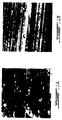
- Figure 1A is a very noisy image that comprises barely any lines.
- Figure 1B is a good quality image with clear lines having a constant orientation.
- a signature based on the image in figure 1A is practically useless while a signature based on the image in figure 1B is very significant. Based on this principle, it is very important to detect regions having a high signal-to-noise ratio. These regions can then be eliminated from the image and won't impact the signature extracted from the image.
- a mask can be created, also called an anisotropic mask, that eliminates the noisy regions before the signature is extracted.
- the mask is actually an image of the same size as the original image wherein the pixels that correspond to the noisy pixels in the original image are set to zero and the pixels with the clear lines are set to one.
- a first module has the principal responsibility of the estimation of the local orientation at each pixel position. This could be accomplished by many different techniques such as texture analysis, Gabor filters, Hough transform or the orientation tensor to name a few. We choose the orientation tensor for its ease of implementation.
- Orilmage that has the same dimension as the original image but where the value associated with each pixel position is the orientation angle comprised between [-90°, 90°].
- the best global alignment angle can easily be found based on the histogram of the orientation image.
- the simplest choice is just the angle for which the histogram attains its maximum value. We found that in practice, this method gives good results. Other more precise techniques could also be used like finding the best Gaussian distribution fitting the histogram and taking the mean of this Gaussian as the best angle.
- Signatures can then be created for all bands and these signatures will be more precise than if we had created only one signature based on a globally aligned image. Therefore, the chances of matching two bullets fired from the same gun are increased.
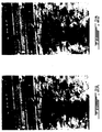
- Figure 2A is an example of an image with regions that comprise clear lines and regions that are very noisy.
- Figure 2B is the same image once the noisy regions have been masked. The pixels in the darkened areas were set to a value of zero in order to be disregarded when the signature is extracted.
- Another embodiment of the present invention consists in eliminating random striation marks that are clearly in an opposite direction from the majority of lines in an image.
- Figure 3A shows a line intersecting a big part of the other lines and going in an opposite direction. These random marks occur sometimes and are not reproducible. They affect the quality of the image signature necessary for correlation.
- the present system can detect a dominant orientation of the striation marks and mask regions having orientations that differ from the dominant orientation.
- the majority of the lines are oriented at 3.5° with respect to the horizontal axis.
- the random mark is a scratch oriented at -75° with respect to the horizontal axis.
- the image in figure 3B has been masked to eliminate all pixels with an orientation that is not within 3.0° of the dominant orientation.
- the threshold tolerance such as 3.0° in this case, can be chosen by the user or can be pre-programmed into the system.
- FIG. 4A is the image with a first mask applied while figure 4C is the image with a second mask applied.
- Detecting if more than one main orientation is present in the image can be done in several ways. For example, by computing the histogram of the orientation image (or one of its sub-region), we can estimate the number of main orientations present. We use a simple criteria based on the number and distribution of the histogram's local maximum. If more than one local maximum exist and they are separated by at least 3°, we conclude that each of these local maximum corresponds to one dominant orientation. Alternatively, if more than one main orientation is present in the image and these orientations are different enough, we can use create a mask that permits us to select only the regions in the image that have an orientation within a given tolerance of a given angle to select the regions corresponding to each main orientation. This would permit us to create signatures that are specific to each of these orientations.
- G is a 2x2 symmetric positive semi definite matrix whose eigenvalues ⁇ 1 ⁇ ⁇ 2 are positives.
- A 1 ⁇ ⁇ 2 / ⁇ 1 from the eigenvalues ⁇ 1 , ⁇ 2 of G.
- ⁇ 2 / ⁇ 1 lies in the interval [0,1]
- A also lies in the interval [0,1].
- a value of zero for A indicates a perfectly isotropic neighborhood where a value of one indicates a perfectly anisotropic neighborhood. In practice, the value of A is almost always somewhere between 0.1 and 0.9.
- the first step consists in identifying at least one region of interest within the image by determining local orientation information comprising elements useful for the specific identification purposes 10.
- the elements are characteristic lines and the characteristic lines are striation marks on a bullet or a bullet casing.
- the pixel positions are assigned an orientation angle.
- the second step comprises creating and applying a mask for the image wherein only the identified regions of interest are exposed 11. If the orientation angle is above a predetermined threshold, the value of the pixel is set to zero.
- the predetermined threshold can be entered by a user. It can also be an angle calculated by the system as a function of the predominant angle.
- the third step comprises extracting a signature for the image by taking into account the regions of interest that were left exposed by the mask and disregarding the regions that were blocked from the image.
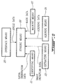
- FIG. 6 is a preferred embodiment for the apparatus of the present invention.
- Storing means 20 are used to store an image.
- Identifying means 21 are for identifying at least one region of interest within the image by determining local orientation information at pixel positions in the image, the region of interest comprising elements useful for the specific identification purposes.
- the elements can be characteristic lines which are striation marks from a bullet or a bullet casing.
- Local orientation data is sent from the identifying means 21 to the storing means 20.
- Masking means 22 are then used to create and apply a mask for the image, wherein only the region of interest is exposed.
- the mask data is sent from the masking means 22 to the storing means 20.
- Extracting means 23 are used to extract a signature for the image, taking into account the region of interest exposed by the mask.
- the image signature data is sent from the extracting means 23 to the storing means 20.
- Aligning means 24 may also be present in the apparatus to align horizontally the elements that are present in the region of interest, transferring aligning data from the aligning means 24 to the storing means 20.
- Interface means are also used for a user to enter a value for a predetermined threshold angle and the angle data is transferred to the storing means 20.
- the identifying means 21 may further comprise means for assigning an orientation angle at each pixel position in the image, means for separating the image into a plurality of vertical bands, wherein the vertical bands are based on groupings of similar orientation angles, and means for detecting lined regions within the image.
- the identifying means may also further comprise computing means for computing three different components of a structure tensor for each pixel in said image, image anisotropy means for creating an anisotropy image wherein each of said pixel is given an anisotropy value computed from said structure tensor, and anisotropy mask means for creating an anisotropy mask from said anisotropy image wherein pixels whose value is greater than a given threshold are set to 1 and pixels whose value is less than a given threshold are set to 0.
- the masking means 22 may further comprise means for assigning a value to zero for each pixel position with an orientation angle above a predetermined threshold, means for determining a dominant orientation angle in the image and assigning a value of zero to the pixel positions with an orientation angle with varies from the dominant angle by more than a predetermined threshold, means for creating and applying separate masks for each dominant angle, and means for calculation the predetermined threshold angle as a function of the predominant angle.
- the extracting means 23 may also comprise means for extracting a signature for each image having a separate mask applied, in the case where more than one mask is applied for one image.
Landscapes
- Engineering & Computer Science (AREA)
- Physics & Mathematics (AREA)
- General Physics & Mathematics (AREA)
- Multimedia (AREA)
- Theoretical Computer Science (AREA)
- Image Analysis (AREA)
Description
- The invention relates to detecting regions of interest in images. More specifically, it relates to automatically detecting lined regions contained inside forensic digital images.
- The traditional way of comparing ballistic evidences such as cartridges and bullets is for a human specialist to manually examine the reference and all the candidates with a comparison microscope. This is a very tedious and time-consuming process that makes matches less likely.
- Recently, a few systems have been invented to automatically perform ballistic image comparisons. For example, the Russian Condor system (Russian patents No.
2130628 2155378 2174251 - One of the critical parts of this operation is the creation of "good" signatures from the acquired images. This is particularly true of non-pristine bullet images, which are very noisy and contain a lot of random marks that are not relevant to the matching operation. These random marks are consciously ignored by a firearm examiner during his visual exam but can seriously compromise the performance of an automated system. To solve this problem, certain systems, such as FEASABLE, ask the user to manually draw the contour of the regions relevant to the matching step over the original reference image. These regions then contain mostly lines that share the same orientation and of course excludes parts of the image that do not contain lines.
- The selected regions alone are then considered for the creation of signatures. Using only the regions determined by the expert dramatically improves the results of the matching process.
- The drawback of this approach is that it takes the knowledge and training of a firearm examiner to select the right regions that will be used for the creation of the signatures. As the number of these experts is much smaller than the number of potential users of the system, this specialized knowledge cannot be expected from the average user.
- Jie Zhou et al, "Algorithm of automatic cartridge identification", Dec. 2001, discloses a method according to the preamble of claim 1.
- An object of the present invention is to extract better quality signatures from images.
Another object of the present invention is to speed up the correlation process for ballistic image comparisons.
Yet another object of the invention is to remove the need to have a firearms examiner participate in the correlation process for ballistic image comparisons. The invention is defined inclaims 1, 21, and 31. Optional features are indicated in the dependent claims.
A mask is created with the property that a value of zero is assigned to each pixel position with an orientation angle above a predetermined threshold and is assigned to 1 otherwise. - A dominant orientation angle in the image is determined and a value of zero is assigned to each pixel position with an orientation angle which varies for the dominant angle by more than a predetermined threshold.
The mask may be created and applied separately for each dominant angle and a signature is calculated for each image having a separate mask applied. - Optionally the image is separated into a plurality of vertical bands, wherein identifying a region of interest, creating and applying a mask, aligning horizontally elements, and calculating a signature is done for each of the plurality of vertical bands. The plurality of vertical bands can also be based on groupings of similar orientation angles.
- These and other features, aspects and advantages of the present invention will become better understood with regard to the following description and accompanying drawings wherein:
-
FIG. 1A is a very noisy image; -
FIG 1B is a low noise image; -
FIG. 2A is an image with a region of high noise; -
FIG 2B is the image ofFig 2A with a mask applied; -
FIG. 3A is an image with a random striation mark; -
FIG 3B is the image ofFig 3A with a mask applied; -
FIG 4A is an image with multiple dominant orientations; -
FIG 4B is the image ofFig 4A with a first mask applied; -
FIG 4C is the image ofFig 4B with a second mask applied; -
FIG 5 is a flow chart of the method of the present invention; and -
FIG. 6 is an embodiment of the apparatus of the present invention. - The most frequently used signatures are 1D signals akin to a vertical profile of the bullet image. Since there is much noise in that kind of image, some care has to be taken before extracting this vertical profile. A simple way to reduce the influence of noise is by averaging the image in the direction of the lines. As the characteristic lines of bullet images are generally tilted by some small angle, typically less than 10 degrees, it is much easier to first align those lines at 0 degree and then simply average along the horizontal direction of the aligned image. Once the image has been rotated so that the characteristic lines are aligned horizontally, signatures can be extracted. This is often done by creating a 1D signal S(x) where the value at position x=L is simply the average gray value of line L of the aligned image. Other statistics could be employed such as the mode or the median.
-
Figure 1A is a very noisy image that comprises barely any lines.Figure 1B is a good quality image with clear lines having a constant orientation. Clearly, a signature based on the image infigure 1A is practically useless while a signature based on the image infigure 1B is very significant. Based on this principle, it is very important to detect regions having a high signal-to-noise ratio. These regions can then be eliminated from the image and won't impact the signature extracted from the image. - A mask can be created, also called an anisotropic mask, that eliminates the noisy regions before the signature is extracted. The mask is actually an image of the same size as the original image wherein the pixels that correspond to the noisy pixels in the original image are set to zero and the pixels with the clear lines are set to one.
- A first module has the principal responsibility of the estimation of the local orientation at each pixel position. This could be accomplished by many different techniques such as texture analysis, Gabor filters, Hough transform or the orientation tensor to name a few. We choose the orientation tensor for its ease of implementation. At the end of this step, we have a real value orientation image named Orilmage that has the same dimension as the original image but where the value associated with each pixel position is the orientation angle comprised between [-90°, 90°].
- Based on this orientation image, we can align horizontally the characteristic lines. This can be done globally or locally (by aligning vertical bands of the image individually).
- Given the orientation image, the best global alignment angle can easily be found based on the histogram of the orientation image. The simplest choice is just the angle for which the histogram attains its maximum value. We found that in practice, this method gives good results. Other more precise techniques could also be used like finding the best Gaussian distribution fitting the histogram and taking the mean of this Gaussian as the best angle.
- As we have observed experimentally, if we split the original image into vertical contiguous bands, some of these bands have an orientation angle that is quite different from the global angle that would have been found by the method described above. This frequently happens in images showing a lot of slippage. For example, the left part of the image could be oriented at 2.5°, the right part at -1.5° while the global orientation could have been 1.0°.
- One way to solve this problem is given by the following algorithm. First, split the original image into a few vertical bands (we use anywhere from 4 to 17 depending on the width of the original image). The idea is to compute one histogram for each of these bands by considering only the corresponding pixels in the orientation image. The best angle for each band can then be found by the same strategy as described above. This allows us to align each band with its own dominant angle, minimizing the effect of slippage.
- Signatures can then be created for all bands and these signatures will be more precise than if we had created only one signature based on a globally aligned image. Therefore, the chances of matching two bullets fired from the same gun are increased.
-
Figure 2A is an example of an image with regions that comprise clear lines and regions that are very noisy.Figure 2B is the same image once the noisy regions have been masked. The pixels in the darkened areas were set to a value of zero in order to be disregarded when the signature is extracted. - Another embodiment of the present invention consists in eliminating random striation marks that are clearly in an opposite direction from the majority of lines in an image.
Figure 3A shows a line intersecting a big part of the other lines and going in an opposite direction. These random marks occur sometimes and are not reproducible. They affect the quality of the image signature necessary for correlation. - Therefore, the present system can detect a dominant orientation of the striation marks and mask regions having orientations that differ from the dominant orientation. In
figure 3A , the majority of the lines are oriented at 3.5° with respect to the horizontal axis. The random mark is a scratch oriented at -75° with respect to the horizontal axis. The image infigure 3B has been masked to eliminate all pixels with an orientation that is not within 3.0° of the dominant orientation. The threshold tolerance, such as 3.0° in this case, can be chosen by the user or can be pre-programmed into the system. - In some cases, there may be more than one dominant orientation. Such is the case in the image in
figure 4A . Certain lines are oriented at about 2.5° with respect to the horizontal axis while others are oriented at about 0°. To extract the best quality signature possible, two separate masks are applied to the image.Figure 4B is the image with a first mask applied whilefigure 4C is the image with a second mask applied. - Detecting if more than one main orientation is present in the image can be done in several ways. For example, by computing the histogram of the orientation image (or one of its sub-region), we can estimate the number of main orientations present. We use a simple criteria based on the number and distribution of the histogram's local maximum. If more than one local maximum exist and they are separated by at least 3°, we conclude that each of these local maximum corresponds to one dominant orientation. Alternatively, if more than one main orientation is present in the image and these orientations are different enough, we can use create a mask that permits us to select only the regions in the image that have an orientation within a given tolerance of a given angle to select the regions corresponding to each main orientation. This would permit us to create signatures that are specific to each of these orientations.
- Another module is responsible for detecting regions that present lined features. As explained before, only the lined regions should be considered when creating signatures. Note that texture analysis could also be used to detect these regions. The idea is to use an anisotropy measure derived from the structure tensor. For each pixel, the structure tensor G is defined as

- Where g is a gaussian smoothed version of the original image and gx 2 is the square of the derivative of g along the X direction, gy 2 is the square of the derivative of g along the Y direction and gxy, is the product of partial derivatives gx and gy. We note that G is a 2x2 symmetric positive semi definite matrix whose eigenvalues λ1 ≥ λ2 are positives.
- At every pixel position, we can compute the anisotropy:

- Working with hundreds of bullet images, we found that the regions that exhibit an anisotropy greater than 0.7 were really lined regions and that regions where the anisotropy was less than 0.4 were almost entirely featureless regions not worth using for signature generation. This observation leads to the following automatic Region Of Interest (ROI) definition based on the anisotropy measure: 1) Compute the three different components of the structure tensor (partial derivatives of the Gaussian smoothed original image); 2) Create an anisotropy image where each pixel is given the anisotropy value A computed from the orientation tensor G; 3) Create an anisotropy mask from the anisotropy image where pixels whose value is greater than a given threshold (for example, 0.7) are set to 1 and the other to 0. This mask could be used independently or in combination with orientation masks created by the first module.
-
Figure 5 describes the method used in the present invention. The first step consists in identifying at least one region of interest within the image by determining local orientation information comprising elements useful for thespecific identification purposes 10. In the preferred embodiment, the elements are characteristic lines and the characteristic lines are striation marks on a bullet or a bullet casing. The pixel positions are assigned an orientation angle. The second step comprises creating and applying a mask for the image wherein only the identified regions of interest are exposed 11. If the orientation angle is above a predetermined threshold, the value of the pixel is set to zero. The predetermined threshold can be entered by a user. It can also be an angle calculated by the system as a function of the predominant angle. The third step comprises extracting a signature for the image by taking into account the regions of interest that were left exposed by the mask and disregarding the regions that were blocked from the image. -
Figure 6 is a preferred embodiment for the apparatus of the present invention. Storing means 20 are used to store an image. Identifying means 21 are for identifying at least one region of interest within the image by determining local orientation information at pixel positions in the image, the region of interest comprising elements useful for the specific identification purposes. For example, the elements can be characteristic lines which are striation marks from a bullet or a bullet casing. Local orientation data is sent from the identifying means 21 to the storing means 20. Masking means 22 are then used to create and apply a mask for the image, wherein only the region of interest is exposed. The mask data is sent from the masking means 22 to the storing means 20. Extracting means 23 are used to extract a signature for the image, taking into account the region of interest exposed by the mask. The image signature data is sent from the extracting means 23 to the storing means 20. - Aligning means 24 may also be present in the apparatus to align horizontally the elements that are present in the region of interest, transferring aligning data from the aligning means 24 to the storing means 20. Interface means are also used for a user to enter a value for a predetermined threshold angle and the angle data is transferred to the storing means 20.
- The identifying means 21 may further comprise means for assigning an orientation angle at each pixel position in the image, means for separating the image into a plurality of vertical bands, wherein the vertical bands are based on groupings of similar orientation angles, and means for detecting lined regions within the image. The identifying means may also further comprise computing means for computing three different components of a structure tensor for each pixel in said image, image anisotropy means for creating an anisotropy image wherein each of said pixel is given an anisotropy value computed from said structure tensor, and anisotropy mask means for creating an anisotropy mask from said anisotropy image wherein pixels whose value is greater than a given threshold are set to 1 and pixels whose value is less than a given threshold are set to 0.
- The masking means 22 may further comprise means for assigning a value to zero for each pixel position with an orientation angle above a predetermined threshold, means for determining a dominant orientation angle in the image and assigning a value of zero to the pixel positions with an orientation angle with varies from the dominant angle by more than a predetermined threshold, means for creating and applying separate masks for each dominant angle, and means for calculation the predetermined threshold angle as a function of the predominant angle.
- The extracting means 23 may also comprise means for extracting a signature for each image having a separate mask applied, in the case where more than one mask is applied for one image.
- It will be understood that numerous modifications thereto will appear to those skilled in the art. Accordingly, the above description and accompanying drawings should be taken as illustrative of the invention and not in a limiting sense. It will further be understood that it is intended to cover any variations, uses, or adaptations of the invention following, in general, the principles of the invention and including such departures from the present disclosure as come within known or customary practice within the art to which the invention pertains and as may be applied to the essential features herein before set forth, and as follows in the scope of the appended claims.
Claims (30)
- A method for an automated system to extract a high quality signature from an image having areas not relevant for specific identification purposes which can lead to misleading image signatures, the method comprising:identifying at least one region of interest within said image by determining local orientation information at pixel positions in said image and further assigning an orientation angle at each said pixel positions in said image, said at least one region of interest comprising elements useful for said specific identification purposes, said identifying a region of interest further comprising detecting lined regions within said image;creating and applying a mask for said image wherein only said at least one region of interest is exposed; andextracting a signature for said image from said at least one region of interest exposed by said mask, characterized in that said extracting a signature comprising assigning a one-dimensional signal to said image and;said creating and applying a mask comprises determining a dominant orientation angle in said image and assigning a value of zero to each said pixel positions with an orientation angle which varies from said dominant angle by more than a predetermined threshold.
- A method as claimed in claim 1, further comprising aligning horizontally said elements present in said at least one region of interest.
- A method as claimed in claim 1, wherein said mask is created and applied separately for each dominant orientation angle.
- A method as claimed in claim 3, wherein said calculating a signature further comprises calculating a signature for each image having a separate mask applied.
- A method as claimed in claim 1, wherein said elements are characteristic lines.
- A method as claimed in claim 5, wherein said characteristic lines are striation marks on one of a bullet and a bullet casing.
- A method as claimed in claim 1, further comprising separating said image into a plurality of vertical bands, wherein identifying a region of interest, creating and applying a mask, aligning horizontally elements, and calculating a signature is done for each of said plurality of vertical bands.
- A method as claimed in claim 1, further comprising separating said image into a plurality of vertical bands based on groupings of similar orientation angles, wherein identifying a region of interest, creating and applying a mask, aligning horizontally elements, and calculating a signature is done for each of said plurality of vertical bands.
- A method as claimed in claim 1, wherein said predetermined threshold is an angle entered by a user.
- A method as claimed in claim 1, wherein said predetermined threshold is an angle calculated as a function of said predominant angle.
- A method as claimed in claim 1, wherein assigning an orientation angle to each pixel position further comprises using a Hough transform.
- A method as claimed in claim 1, wherein assigning an orientation angle to each pixel position further comprises using an orientation tensor.
- A method as claimed in claim 1, wherein said determining a dominant angle further comprises producing a histogram of said image and identifying an angle at which said histogram attains its maximum value as said dominant angle.
- A method as claimed in claim 13, wherein more than one dominant angle is said to exist if said histogram contains more than one local maximum and said more than one local maximum are separated by at least three degrees.
- A method as claimed in claim 1, wherein said detecting lined regions comprises:computing three different components of a structure tensor for each pixel in said image; creating an anisotropy image wherein each of said pixel is given an anisotropy value computed from said structure tensor; creating an anisotropy mask from said anisotropy image wherein pixels whose value is greater than a given threshold are set to 1 and pixels whose value is less than a given threshold are set to 0.
- A method as claimed in claim 15, wherein said anisotropy value lies in the interval [0, 1].
- A method as claimed in claim 16, wherein said given threshold is 0.7.
- A method as claimed in claim 15, wherein said three different components are partial derivatives of a Gaussian smoothed version of said image.
- A method as claimed in claim 15, wherein said structure tensor is a 2x2 symmetric positive semi definite matrix whose eigenvalues are positive.
- An apparatus for an automated system to extract a high quality signature from an image having areas not relevant for specific identification purposes which can lead to misleading image signatures, the apparatus comprising;
storing means to store an image;
identifying means for identifying at least one region of interest within said image by determining local orientation information at pixel positions in said image and further assigning an orientation angle at each said pixel positions in said image, said at least one region of interest comprising elements useful for said specific identification purposes, said identifying means further comprising means for detecting lined regions within said image;
masking means for creating and applying a mask for said image wherein only said at least one region of interest is exposed; and
extracting means for extracting a signature for said image from said at least one region of interest exposed by said mask;
characterized in that said extracting means comprising means for assigning a one-dimensional signal to said image and said masking means comprise means for determining a dominant orientation angle in said image and assigning a value of zero to each said pixel positions with an orientation angle which varies from said dominant angle by more than a predetermined threshold. - An apparatus as claimed in claim 20, further comprising aligning means to align horizontally said elements present in said at least one region of interest.
- An apparatus as claimed in claim 21, wherein said masking means further comprises means for creating and applying separate masks for each of said dominant orientation angle.
- An apparatus as claimed in claim 22, wherein said extracting means further comprises means for extracting a signature for each image having, a separate mask applied.
- An apparatus as claimed in claim 20, wherein said identifying means further comprising separating means for separating said image into a plurality of vertical bands.
- An apparatus as claimed in claim 24, wherein said separating means further comprises means for separating said image into a plurality of vertical bands based on groupings of similar orientation angles.
- An apparatus as claimed in claim 20, further comprising interface means for a user to enter a value for said predetermined threshold angle.
- An apparatus as claimed in claim 20, wherein said masking means further comprises calculating means for calculating said predetermined threshold angle as a function of said predominant angle.
- An apparatus as claimed in claim 20, wherein said identifying means further comprises:computing means for computing three different components of a structure tensor for each pixel in said image;image anisotropy means for creating an anisotropy image wherein each of said pixel is given an anisotropy value computed from said structure tensor; andanisotropy mask means for creating an anisotropy mask from said anisotropy image wherein pixels whose value is greater than a given threshold are set to 1 and pixels whose value is less than a given threshold are set to 0.
- A computer readable memory for storing programmable instructions for use in the execution in a computer of the method of any one of claims 1 to 19.
- A computer data signal embodied in a carrier wave comprising data resulting from a method for an automated system to extract a high quality signature from an image having areas not relevant for specific identification purposes which can lead to misleading image signatures, the method comprising:identifying at least one region of interest within said image by determining local orientation information at pixel positions in said image and further assigning an orientation angle at each said pixel positions in said image, said at least one region of interest comprising elements useful for said specific identification purposes, said identifying a region of interest further comprising detecting lined regions within said image;creating and applying a mask for said image wherein only said at least one region of interest is exposed and extracting a signature for said image from said at least one region of interest exposed by said mask characterized in that said creating and applying a mask comprisesdetermining a dominant orientation angle in said image and assigning a value of zero to each said pixel positions with an orientation angle which varies from said dominant angle by more than a predetermined threshold; and said extracting a signature comprises assigning a one-dimensional signal to said image.
Applications Claiming Priority (3)
| Application Number | Priority Date | Filing Date | Title |
|---|---|---|---|
| US30809502A | 2002-12-03 | 2002-12-03 | |
| US308095 | 2002-12-03 | ||
| PCT/CA2003/001894 WO2004051570A2 (en) | 2002-12-03 | 2003-12-03 | Method for automatically defining regions of interest for matching and visualizing forensic images |
Publications (2)
| Publication Number | Publication Date |
|---|---|
| EP1567983A2 EP1567983A2 (en) | 2005-08-31 |
| EP1567983B1 true EP1567983B1 (en) | 2016-05-25 |
Family
ID=32467800
Family Applications (1)
| Application Number | Title | Priority Date | Filing Date |
|---|---|---|---|
| EP03767326.6A Expired - Lifetime EP1567983B1 (en) | 2002-12-03 | 2003-12-03 | Method for automatically defining regions of interest for matching and visualizing forensic images |
Country Status (5)
| Country | Link |
|---|---|
| US (1) | US7565014B2 (en) |
| EP (1) | EP1567983B1 (en) |
| AU (1) | AU2003291868A1 (en) |
| CA (1) | CA2505194C (en) |
| WO (1) | WO2004051570A2 (en) |
Families Citing this family (5)
| Publication number | Priority date | Publication date | Assignee | Title |
|---|---|---|---|---|
| US8073248B2 (en) * | 2007-06-08 | 2011-12-06 | Apple Inc. | Automatic detection of calibration charts in images |
| US8326048B2 (en) * | 2007-10-04 | 2012-12-04 | Microsoft Corporation | Geo-relevance for images |
| US8477188B2 (en) * | 2009-10-14 | 2013-07-02 | Harris Corporation | Surveillance system for transcoding surveillance image files while retaining geospatial metadata and associated methods |
| FR3026211B1 (en) * | 2014-09-19 | 2017-12-08 | Univ Aix Marseille | METHOD FOR IDENTIFYING THE ANISOTROPY OF THE TEXTURE OF A DIGITAL IMAGE |
| FR3059128B1 (en) * | 2016-11-24 | 2020-01-10 | Universite D'aix-Marseille | METHOD FOR CHARACTERIZING THE ANISOTROPY OF THE TEXTURE OF A DIGITAL IMAGE |
Family Cites Families (4)
| Publication number | Priority date | Publication date | Assignee | Title |
|---|---|---|---|---|
| US5390108A (en) * | 1991-05-24 | 1995-02-14 | Forensic Technology Wai Inc. | Computer automated bullet analysis apparatus |
| JP3403875B2 (en) * | 1995-10-16 | 2003-05-06 | 大日本スクリーン製造株式会社 | Three-dimensional measurement method and display method, and three-dimensional measurement device |
| US6965645B2 (en) * | 2001-09-25 | 2005-11-15 | Microsoft Corporation | Content-based characterization of video frame sequences |
| JP4053345B2 (en) * | 2002-04-25 | 2008-02-27 | シャープ株式会社 | Image processing method, image processing apparatus, image forming apparatus including the same, program, and recording medium |
-
2003
- 2003-12-03 EP EP03767326.6A patent/EP1567983B1/en not_active Expired - Lifetime
- 2003-12-03 WO PCT/CA2003/001894 patent/WO2004051570A2/en not_active Ceased
- 2003-12-03 CA CA2505194A patent/CA2505194C/en not_active Expired - Lifetime
- 2003-12-03 AU AU2003291868A patent/AU2003291868A1/en not_active Abandoned
-
2005
- 2005-05-31 US US11/140,090 patent/US7565014B2/en active Active
Also Published As
| Publication number | Publication date |
|---|---|
| EP1567983A2 (en) | 2005-08-31 |
| WO2004051570A3 (en) | 2004-12-29 |
| WO2004051570A2 (en) | 2004-06-17 |
| US20050207650A1 (en) | 2005-09-22 |
| AU2003291868A1 (en) | 2004-06-23 |
| CA2505194A1 (en) | 2004-06-17 |
| US7565014B2 (en) | 2009-07-21 |
| CA2505194C (en) | 2011-03-29 |
Similar Documents
| Publication | Publication Date | Title |
|---|---|---|
| EP3176751B1 (en) | Information processing device, information processing method, computer-readable recording medium, and inspection system | |
| Kamble et al. | Localization of optic disc and fovea in retinal images using intensity based line scanning analysis | |
| US20170344846A1 (en) | Image processing apparatus, image processing method and program | |
| EP2294531A1 (en) | Scale robust feature-based identifiers for image identification | |
| Li et al. | Automatic visual/IR image registration | |
| US20180174328A1 (en) | Turning radius-based corner detection algorithm | |
| EP2289024B1 (en) | Method for automatic region segmentation on cartridge case base and selection of the best mark region for cartridge case comparison | |
| US8867844B2 (en) | Edge based template matching | |
| US20240104886A1 (en) | Method, computer program, profile identification device | |
| CN112926695A (en) | Image recognition method and system based on template matching | |
| CN117710399A (en) | Crack contour extraction method in geological survey based on vision | |
| US7565014B2 (en) | Method for automatically defining regions of interest for matching and visualizing forensic images | |
| CN118397239A (en) | Image time identification recognition method based on template matching | |
| CN110969594A (en) | Image splicing method | |
| WO2002029712A2 (en) | System and method for pattern identification | |
| CN117773423A (en) | A kind of weld seam tracking processing method | |
| EP4012656B1 (en) | Method for real-time tow ball detection | |
| CN104268550A (en) | Feature extraction method and device | |
| US7272242B2 (en) | Object detection in electro-optic sensor images | |
| Geradts et al. | Pattern recognition in a database of cartridge cases | |
| DE102019102561A1 (en) | Process for recognizing a plaster marking | |
| CN100357956C (en) | Method for Binarizing Images Containing Linear Structures | |
| CHETVERIKOV et al. | Affine-invariant texture classification using regularity features | |
| Bandeira et al. | Enhancing impact crater contours to increase recognition rates | |
| Стах et al. | Method for estimating probabilities of target detection and recognition by their dimensional signatures in digital images from the sightseeing complex of armoured vehicle weapon systems |
Legal Events
| Date | Code | Title | Description |
|---|---|---|---|
| PUAI | Public reference made under article 153(3) epc to a published international application that has entered the european phase |
Free format text: ORIGINAL CODE: 0009012 |
|
| 17P | Request for examination filed |
Effective date: 20050519 |
|
| AK | Designated contracting states |
Kind code of ref document: A2 Designated state(s): AT BE BG CH CY CZ DE DK EE ES FI FR GB GR HU IE IT LI LU MC NL PT RO SE SI SK TR |
|
| AX | Request for extension of the european patent |
Extension state: AL LT LV MK |
|
| DAX | Request for extension of the european patent (deleted) | ||
| 17Q | First examination report despatched |
Effective date: 20080229 |
|
| GRAP | Despatch of communication of intention to grant a patent |
Free format text: ORIGINAL CODE: EPIDOSNIGR1 |
|
| INTG | Intention to grant announced |
Effective date: 20151218 |
|
| RAP1 | Party data changed (applicant data changed or rights of an application transferred) |
Owner name: ULTRA ELECTRONICS FORENSIC TECHNOLOGY INC. |
|
| GRAS | Grant fee paid |
Free format text: ORIGINAL CODE: EPIDOSNIGR3 |
|
| GRAA | (expected) grant |
Free format text: ORIGINAL CODE: 0009210 |
|
| AK | Designated contracting states |
Kind code of ref document: B1 Designated state(s): AT BE BG CH CY CZ DE DK EE ES FI FR GB GR HU IE IT LI LU MC NL PT RO SE SI SK TR |
|
| REG | Reference to a national code |
Ref country code: GB Ref legal event code: FG4D |
|
| REG | Reference to a national code |
Ref country code: CH Ref legal event code: EP |
|
| REG | Reference to a national code |
Ref country code: IE Ref legal event code: FG4D Ref country code: AT Ref legal event code: REF Ref document number: 802872 Country of ref document: AT Kind code of ref document: T Effective date: 20160615 |
|
| REG | Reference to a national code |
Ref country code: DE Ref legal event code: R096 Ref document number: 60348983 Country of ref document: DE |
|
| REG | Reference to a national code |
Ref country code: NL Ref legal event code: MP Effective date: 20160525 |
|
| PG25 | Lapsed in a contracting state [announced via postgrant information from national office to epo] |
Ref country code: FI Free format text: LAPSE BECAUSE OF FAILURE TO SUBMIT A TRANSLATION OF THE DESCRIPTION OR TO PAY THE FEE WITHIN THE PRESCRIBED TIME-LIMIT Effective date: 20160525 Ref country code: NL Free format text: LAPSE BECAUSE OF FAILURE TO SUBMIT A TRANSLATION OF THE DESCRIPTION OR TO PAY THE FEE WITHIN THE PRESCRIBED TIME-LIMIT Effective date: 20160525 |
|
| REG | Reference to a national code |
Ref country code: AT Ref legal event code: MK05 Ref document number: 802872 Country of ref document: AT Kind code of ref document: T Effective date: 20160525 |
|
| PG25 | Lapsed in a contracting state [announced via postgrant information from national office to epo] |
Ref country code: ES Free format text: LAPSE BECAUSE OF FAILURE TO SUBMIT A TRANSLATION OF THE DESCRIPTION OR TO PAY THE FEE WITHIN THE PRESCRIBED TIME-LIMIT Effective date: 20160525 Ref country code: SE Free format text: LAPSE BECAUSE OF FAILURE TO SUBMIT A TRANSLATION OF THE DESCRIPTION OR TO PAY THE FEE WITHIN THE PRESCRIBED TIME-LIMIT Effective date: 20160525 Ref country code: PT Free format text: LAPSE BECAUSE OF FAILURE TO SUBMIT A TRANSLATION OF THE DESCRIPTION OR TO PAY THE FEE WITHIN THE PRESCRIBED TIME-LIMIT Effective date: 20160926 Ref country code: GR Free format text: LAPSE BECAUSE OF FAILURE TO SUBMIT A TRANSLATION OF THE DESCRIPTION OR TO PAY THE FEE WITHIN THE PRESCRIBED TIME-LIMIT Effective date: 20160826 |
|
| PG25 | Lapsed in a contracting state [announced via postgrant information from national office to epo] |
Ref country code: IT Free format text: LAPSE BECAUSE OF FAILURE TO SUBMIT A TRANSLATION OF THE DESCRIPTION OR TO PAY THE FEE WITHIN THE PRESCRIBED TIME-LIMIT Effective date: 20160525 |
|
| PG25 | Lapsed in a contracting state [announced via postgrant information from national office to epo] |
Ref country code: EE Free format text: LAPSE BECAUSE OF FAILURE TO SUBMIT A TRANSLATION OF THE DESCRIPTION OR TO PAY THE FEE WITHIN THE PRESCRIBED TIME-LIMIT Effective date: 20160525 Ref country code: DK Free format text: LAPSE BECAUSE OF FAILURE TO SUBMIT A TRANSLATION OF THE DESCRIPTION OR TO PAY THE FEE WITHIN THE PRESCRIBED TIME-LIMIT Effective date: 20160525 Ref country code: SK Free format text: LAPSE BECAUSE OF FAILURE TO SUBMIT A TRANSLATION OF THE DESCRIPTION OR TO PAY THE FEE WITHIN THE PRESCRIBED TIME-LIMIT Effective date: 20160525 Ref country code: RO Free format text: LAPSE BECAUSE OF FAILURE TO SUBMIT A TRANSLATION OF THE DESCRIPTION OR TO PAY THE FEE WITHIN THE PRESCRIBED TIME-LIMIT Effective date: 20160525 Ref country code: CZ Free format text: LAPSE BECAUSE OF FAILURE TO SUBMIT A TRANSLATION OF THE DESCRIPTION OR TO PAY THE FEE WITHIN THE PRESCRIBED TIME-LIMIT Effective date: 20160525 |
|
| PG25 | Lapsed in a contracting state [announced via postgrant information from national office to epo] |
Ref country code: BE Free format text: LAPSE BECAUSE OF FAILURE TO SUBMIT A TRANSLATION OF THE DESCRIPTION OR TO PAY THE FEE WITHIN THE PRESCRIBED TIME-LIMIT Effective date: 20160525 Ref country code: AT Free format text: LAPSE BECAUSE OF FAILURE TO SUBMIT A TRANSLATION OF THE DESCRIPTION OR TO PAY THE FEE WITHIN THE PRESCRIBED TIME-LIMIT Effective date: 20160525 |
|
| REG | Reference to a national code |
Ref country code: DE Ref legal event code: R097 Ref document number: 60348983 Country of ref document: DE |
|
| PLBE | No opposition filed within time limit |
Free format text: ORIGINAL CODE: 0009261 |
|
| STAA | Information on the status of an ep patent application or granted ep patent |
Free format text: STATUS: NO OPPOSITION FILED WITHIN TIME LIMIT |
|
| 26N | No opposition filed |
Effective date: 20170228 |
|
| PG25 | Lapsed in a contracting state [announced via postgrant information from national office to epo] |
Ref country code: SI Free format text: LAPSE BECAUSE OF FAILURE TO SUBMIT A TRANSLATION OF THE DESCRIPTION OR TO PAY THE FEE WITHIN THE PRESCRIBED TIME-LIMIT Effective date: 20160525 |
|
| REG | Reference to a national code |
Ref country code: DE Ref legal event code: R119 Ref document number: 60348983 Country of ref document: DE |
|
| REG | Reference to a national code |
Ref country code: CH Ref legal event code: PL |
|
| GBPC | Gb: european patent ceased through non-payment of renewal fee |
Effective date: 20161203 |
|
| PG25 | Lapsed in a contracting state [announced via postgrant information from national office to epo] |
Ref country code: MC Free format text: LAPSE BECAUSE OF FAILURE TO SUBMIT A TRANSLATION OF THE DESCRIPTION OR TO PAY THE FEE WITHIN THE PRESCRIBED TIME-LIMIT Effective date: 20160525 |
|
| REG | Reference to a national code |
Ref country code: FR Ref legal event code: ST Effective date: 20170831 |
|
| REG | Reference to a national code |
Ref country code: IE Ref legal event code: MM4A |
|
| PG25 | Lapsed in a contracting state [announced via postgrant information from national office to epo] |
Ref country code: CH Free format text: LAPSE BECAUSE OF NON-PAYMENT OF DUE FEES Effective date: 20161231 Ref country code: FR Free format text: LAPSE BECAUSE OF NON-PAYMENT OF DUE FEES Effective date: 20170102 Ref country code: LU Free format text: LAPSE BECAUSE OF NON-PAYMENT OF DUE FEES Effective date: 20161203 Ref country code: LI Free format text: LAPSE BECAUSE OF NON-PAYMENT OF DUE FEES Effective date: 20161231 |
|
| PG25 | Lapsed in a contracting state [announced via postgrant information from national office to epo] |
Ref country code: GB Free format text: LAPSE BECAUSE OF NON-PAYMENT OF DUE FEES Effective date: 20161203 Ref country code: DE Free format text: LAPSE BECAUSE OF NON-PAYMENT OF DUE FEES Effective date: 20170701 Ref country code: IE Free format text: LAPSE BECAUSE OF NON-PAYMENT OF DUE FEES Effective date: 20161203 |
|
| PG25 | Lapsed in a contracting state [announced via postgrant information from national office to epo] |
Ref country code: CY Free format text: LAPSE BECAUSE OF FAILURE TO SUBMIT A TRANSLATION OF THE DESCRIPTION OR TO PAY THE FEE WITHIN THE PRESCRIBED TIME-LIMIT Effective date: 20160525 Ref country code: HU Free format text: LAPSE BECAUSE OF FAILURE TO SUBMIT A TRANSLATION OF THE DESCRIPTION OR TO PAY THE FEE WITHIN THE PRESCRIBED TIME-LIMIT; INVALID AB INITIO Effective date: 20031203 |
|
| PG25 | Lapsed in a contracting state [announced via postgrant information from national office to epo] |
Ref country code: TR Free format text: LAPSE BECAUSE OF FAILURE TO SUBMIT A TRANSLATION OF THE DESCRIPTION OR TO PAY THE FEE WITHIN THE PRESCRIBED TIME-LIMIT Effective date: 20160525 |
|
| PG25 | Lapsed in a contracting state [announced via postgrant information from national office to epo] |
Ref country code: BG Free format text: LAPSE BECAUSE OF FAILURE TO SUBMIT A TRANSLATION OF THE DESCRIPTION OR TO PAY THE FEE WITHIN THE PRESCRIBED TIME-LIMIT Effective date: 20160525 |