EP1567831B1 - Potentiometer - Google Patents
Potentiometer Download PDFInfo
- Publication number
- EP1567831B1 EP1567831B1 EP03778511A EP03778511A EP1567831B1 EP 1567831 B1 EP1567831 B1 EP 1567831B1 EP 03778511 A EP03778511 A EP 03778511A EP 03778511 A EP03778511 A EP 03778511A EP 1567831 B1 EP1567831 B1 EP 1567831B1
- Authority
- EP
- European Patent Office
- Prior art keywords
- potentiometer
- resistor
- contactor
- contact
- fingers
- Prior art date
- Legal status (The legal status is an assumption and is not a legal conclusion. Google has not performed a legal analysis and makes no representation as to the accuracy of the status listed.)
- Expired - Lifetime
Links
- 239000004020 conductor Substances 0.000 claims abstract description 17
- 230000008878 coupling Effects 0.000 claims abstract description 7
- 238000010168 coupling process Methods 0.000 claims abstract description 7
- 238000005859 coupling reaction Methods 0.000 claims abstract description 7
- 238000003780 insertion Methods 0.000 claims description 7
- 230000037431 insertion Effects 0.000 claims description 7
- 239000000463 material Substances 0.000 claims description 6
- 229910001220 stainless steel Inorganic materials 0.000 claims description 5
- 239000010935 stainless steel Substances 0.000 claims description 5
- 230000009471 action Effects 0.000 claims description 4
- 238000005452 bending Methods 0.000 claims description 4
- 239000002991 molded plastic Substances 0.000 claims description 4
- 239000000853 adhesive Substances 0.000 description 7
- 230000001070 adhesive effect Effects 0.000 description 7
- 239000010970 precious metal Substances 0.000 description 7
- 239000011324 bead Substances 0.000 description 4
- 230000008901 benefit Effects 0.000 description 4
- 238000007373 indentation Methods 0.000 description 3
- 238000004519 manufacturing process Methods 0.000 description 3
- 239000002184 metal Substances 0.000 description 3
- 238000006073 displacement reaction Methods 0.000 description 2
- 238000000034 method Methods 0.000 description 2
- 239000004033 plastic Substances 0.000 description 2
- 229920003023 plastic Polymers 0.000 description 2
- 210000002105 tongue Anatomy 0.000 description 2
- 230000015572 biosynthetic process Effects 0.000 description 1
- 230000008859 change Effects 0.000 description 1
- 238000002788 crimping Methods 0.000 description 1
- 230000001419 dependent effect Effects 0.000 description 1
- 230000006866 deterioration Effects 0.000 description 1
- 210000003734 kidney Anatomy 0.000 description 1
- 238000005192 partition Methods 0.000 description 1
- 230000008569 process Effects 0.000 description 1
- 230000004044 response Effects 0.000 description 1
- 230000035945 sensitivity Effects 0.000 description 1
- 238000000926 separation method Methods 0.000 description 1
- 239000007787 solid Substances 0.000 description 1
Images

Classifications
-
- G—PHYSICS
- G01—MEASURING; TESTING
- G01D—MEASURING NOT SPECIALLY ADAPTED FOR A SPECIFIC VARIABLE; ARRANGEMENTS FOR MEASURING TWO OR MORE VARIABLES NOT COVERED IN A SINGLE OTHER SUBCLASS; TARIFF METERING APPARATUS; MEASURING OR TESTING NOT OTHERWISE PROVIDED FOR
- G01D5/00—Mechanical means for transferring the output of a sensing member; Means for converting the output of a sensing member to another variable where the form or nature of the sensing member does not constrain the means for converting; Transducers not specially adapted for a specific variable
- G01D5/12—Mechanical means for transferring the output of a sensing member; Means for converting the output of a sensing member to another variable where the form or nature of the sensing member does not constrain the means for converting; Transducers not specially adapted for a specific variable using electric or magnetic means
- G01D5/14—Mechanical means for transferring the output of a sensing member; Means for converting the output of a sensing member to another variable where the form or nature of the sensing member does not constrain the means for converting; Transducers not specially adapted for a specific variable using electric or magnetic means influencing the magnitude of a current or voltage
- G01D5/16—Mechanical means for transferring the output of a sensing member; Means for converting the output of a sensing member to another variable where the form or nature of the sensing member does not constrain the means for converting; Transducers not specially adapted for a specific variable using electric or magnetic means influencing the magnitude of a current or voltage by varying resistance
- G01D5/165—Mechanical means for transferring the output of a sensing member; Means for converting the output of a sensing member to another variable where the form or nature of the sensing member does not constrain the means for converting; Transducers not specially adapted for a specific variable using electric or magnetic means influencing the magnitude of a current or voltage by varying resistance by relative movement of a point of contact or actuation and a resistive track
-
- G—PHYSICS
- G01—MEASURING; TESTING
- G01D—MEASURING NOT SPECIALLY ADAPTED FOR A SPECIFIC VARIABLE; ARRANGEMENTS FOR MEASURING TWO OR MORE VARIABLES NOT COVERED IN A SINGLE OTHER SUBCLASS; TARIFF METERING APPARATUS; MEASURING OR TESTING NOT OTHERWISE PROVIDED FOR
- G01D11/00—Component parts of measuring arrangements not specially adapted for a specific variable
- G01D11/24—Housings ; Casings for instruments
- G01D11/245—Housings for sensors
Definitions
- Another aim of the present invention is to provide a rotary potentiometer in which the components can be quickly and conveniently assembled or replaced.
- the upper housing 10 a is further provided with a flange 70 extending radially beyond the lower housing 10 b .
- Arc-shaped slots 72 are formed in the flange 70 for receiving screws or bolts for mounting the potentiometer by screwing into mounting holes provided at a mounting location on the engine.
- the shaft 50, wiper carrier 54, spring contact 56 and wiper 60 are mounted in the upper housing 10 a which is then lowered onto the lower housing 10 b so that the precious metal bead 58 contacts the conductive boss 28, the precious metal wiper contact 62 contacts the resistor coil 42 and the upper housing 10 a engages the lower housing 10 b to form a seal against the O-ring 14. Finally, the upper housing 10 a is pushed over the O-ring seal 41 onto the lower housing 10 b and the two housings 10 a , 10 b are held together crimping of the metal ring 12. The complete assembly is a sealed unit with the electrical components sealed into the body 10 and protected from ingress of moisture or dirt.
Landscapes
- Physics & Mathematics (AREA)
- General Physics & Mathematics (AREA)
- Adjustable Resistors (AREA)
- Measurement Of Length, Angles, Or The Like Using Electric Or Magnetic Means (AREA)
- Surgical Instruments (AREA)
Abstract
Description
- The present invention relates to a potentiometer. In particular, but not exclusively, the present invention relates to a rotary potentiomenter.
- Transducers are used in a wide range of control and instrumentation applications to provide an electrical signal which is indicative of a position of a member of the transducer. Typically, the member is coupled to a moveable actuator component in a piece of machinery such as an engine, wherein the actuator component position is determined by an operating condition or parameter of the engine. A particular example is a potentiometer used in a racing car engine for providing a feedback signal indicative of a throttle position.
- A rotary potentiometer has a rotatable shaft that drives a wiper. The wiper contacts and is movable across a resistor which is disposed in a circular arc around the shaft axis. Typically, the resistor is a wound wire coil. A voltage is applied across the two ends of the resistor coil and an output voltage is sensed on the wiper. The output voltage is dependent on the position of the wiper relative to the ends of the resistor.
US 2442630 andEP 0389669 show examples for rotary potentiometers. - One problem with known rotary transducers is that of backlash. The shaft member must be suitably coupled to the actuator component within the engine. For instance, in the racing car throttle example, the shaft of the potentiometer must be coupled to a butterfly valve member of the throttle. Backlash is liable to be generated in any such coupling, giving rise to inaccuracies and hysteresis in the output signal. Backlash may be reduced or eliminated by insertion of a fastener such as a screw or spring clip to hold the shaft rigidly to the component. However, engine vibrations may cause the fastener to become dislodged or fall out of the coupling into the engine, leading to engine failure.
- For a rotary potentiometer, the angle of rotation of the arc through which the potentiometer wiper moves (the operating angle) may be anything from a fairly small angle (say 10°) to a large angle (say 350°). The angle required for a given transducer application depends on the angle through which the actuator component of the engine rotates. Ideally, to obtain a full range of output signal voltage, the angular positions of the ends of the resistor should correspond to the extents of angular movement of the actuator component.
To satisfy demand, manufacturers of such rotary potentiometers provide a range of different products each having a different operating angle.
However, conventional manufacturing constraints place a practical and/or commercial limit on the number of different products in a product range.
Thus there is a limited number of different operating angles available in a given product range. This causes a design problem. The designer must make a compromise when selecting the potentiometer between the angle of rotation of the actuator component and the available operating angles of the potentiometer. - A requirement of rotary potentiometers is that the resistor is fixed relative to the housing and must remain in position throughout the operational life of the potentiometer, even where there are severe conditions such as engine vibrations. Known potentiometer resistor coils are fixed to the transducer mounting by means of an adhesive. However, adhesive bonds are liable to deteriorate and to work loose with vibrations. Furthermore, the application of adhesive in the manufacturing assembly is a time-consuming operation.
- It is an aim of the present invention to provide a potentiometer rotary potentiometer which alleviates these problems.
- A further aim of the present invention is to provide a rotary potentiometer which facilitates small angular adjustments to be made to a mounted position of the potentiometer
- Another aim of the present invention is to provide a potentiometer which is not susceptible to mechanical or electrical deterioration caused by vibrations.
- Another aim of the present invention is to provide a rotary potentiometer in which the components can be quickly and conveniently assembled or replaced.
- According to one aspect of the present invention there is provided a rotary potentiometer for providing an output signal indicative of an angular position of a component, the potentiometer comprising:
- a body; and
- a shaft having an axis, the shaft being rotatable about the axis relative to the body and having an end portion for insertion into an aperture of said component,
- Preferably the end portion is an integral part of the shaft. The resilient gripping action between the end portion of the shaft and the component forms a substantially backlash free coupling. It is an advantage that this coupling may be without additional components that could become dislodged.
- Preferably the segments are provided with a bevelled end face to facilitate insertion into the aperture by squeezing of the segments toward the axis when the bevelled face is pushed against edges of the aperture.
- In another aspect of the invention, embodiments have a body comprising an axially centred circular flange for mounting of the potentiometer by threaded fastening means. Arcuate slots may be provided in the flange for insertion of the fastening means therethrough. The arcuate slots allow for angular positional adjustment of the potentiometer.
- Preferably the flange is further provided with mounting inserts surrounding each arcuate slot, the inserts having a face for abutting a head of a fastener when the fastener is tightened. The mounting inserts may be of a stainless steel or other durable material which resists permanent deformation when the fastener is tightened.
- In prior art rotary potentiometer, when mounting screws are tightened the plastics material of the flange is permanently deformed leaving an indentation underneath the head of the screw. The angular position of the mounting of the potentiometer may be of critical importance for the required accuracy and sensitivity of the potentiometer. In such circumstances it is often necessary to make small adjustments to the angular position at which the potentiometer is mounted. However, the screws will tend to reseat in the indentations in the flange, thereby tending to move the potentiometer back towards its original position. The stainless steel inserts prevent the formation of permanent indentations and therefore facilitate small angular adjustments of the potentiometer
- In another aspect of the invention, the potentiometer has electrical connections for providing a supply voltage to the potentiometer and for providing an output signal from the potentiometer to an instrument panel or controller. The electrical connections are preferably provided by way of a multi-core cable which may be permanently moulded into the moulded plastics body of the transducer. It is an advantage that the electrical connection terminals can be located remotely from the transducer so that vibrations in the vicinity of the potentiometer cannot cause the terminal connections to become loose.
- According to the main aspect of the present invention there is provided a potentiometer for providing an output signal indicative of a position of a component, the potentiometer comprising:
- a body;
- a member moveable relative to the body and having an end portion for coupling to said component;
- a resistor mounted to the body;
- a wiper coupled to the member and forming a slidable electrical contact to the resistor; and
- contactor means for providing selectable contact positions to said resistor of respective first and second electrical conductors, so as to provide a selected operating section of said resistor.
- In a preferred embodiment, the potentiometer is a rotary potentiometer for providing an output signal indicative of an angular position of said component, wherein:
- said member is a shaft having an axis, the shaft being rotatable about the axis relative to the body;
- said resistor is mounted to the body in an arc around the axis; and
- said contactor means is operative for providing selectable contact positions to said resistor, so as to provide a selected operating angle of said potentiometer.
- Preferably, the resistor comprises a resistor coil.
- In a preferred embodiment, the contactor means comprises a plurality of contactor fingers, the contact point being selectable by selection of a finger and positioning of the selected finger into contact with the resistor. The contactor fingers may be fingers of a contactor plate, the selected contactor finger being positioned by bending the finger relative to the plate so as to contact the resistor. Alternatively, the contactor finger may be selected by bending unselected fingers relative to the plate so that only the selected finger contacts the resistor. Preferably, the contactor fingers are arranged around the contactor plate to provide a range of selectable operating angles between 0 and 360 degrees.
- It is an advantage that a single component (the contactor plate) can be manufactured and used in potentiometers of any required operating angle.
All that is required to provide a potentiometer of a required operating angle is to select the appropriate finger having the required angular position. - Conveniently, the potentiometer is provided with two contactor plates, one for connection of each of the first and second electrical conductors to the resistor. This advantageously allows for greater flexibility in the selected positions of the contacts since a contact finger on each plate can be selected.
Not only is the operating angle selectable, but also the angular disposition of the operating angle relative to the body of the potentiometer is selectable. - Preferably the, or each, contactor plate is mountable to the body by press fitting over a resilient protrusion formed on the body.
- In a preferred embodiment the resistor coil is mounted to the body by means of a mounting ring which clamps the coil between the mounting ring and the body. Preferably, the clamping ring is mountable to the body by press fitting over a resilient protrusion formed on the body.
- It is an advantage that the use of press-fit components allows for quick and convenient assembly of the potentiometer. Components can be quickly and conveniently changed or replaced. The resistor component is fixed relative to the housing and must remain in position throughout the operational life of the component, even where there are severe conditions such as engine vibrations. A problem with prior art rotary potentiometers is that the resistor coils are fixed to the potentiometer mounting by means of an adhesive.
- However, adhesive bonds are liable to deteriorate and to work loose with vibrations. The application of adhesive in the manufacturing assembly is a time-consuming operation. The replacement of adhesive mounted coils is also time-consuming and can be a messy procedure.
- The invention will now be described by way of example with reference to the accompanying drawings in which:-
-
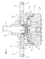
Figure 1 is a sectional elevation of a potentiometer in accordance with the present invention; -
Figure 2 is a detailed view of part of a shaft forming part of the potentiometer ofFigure 1 ; -
Figure 3 is a mounting insert for use with the potentiometer ofFigure 1 ; -
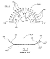
Figure 4 is a view of a contact plate forming part of the potentiometer ofFigure 1 ; and -
Figure 5 is a sectional view taken along the line A-A ofFigure 4 . - Referring to
Figure 1 , a potentiometer has ahousing 10 formed from a mouldable plastics material. Thehousing 10 is formed of two parts, anupper housing 10a and alower housing 10b. The potentiometer is one typically used for mounting to an engine as part of a control instrument. The potentiometer has ashaft 50 which is formed to engage an aperture in a component of the engine. The component is one which is rotatably driven to an angular position in response to a change of a physical parameter of the engine. - The
lower housing 10b carries the stationary components of a potentiometer and is joined to theupper housing 10a by means of a crimpedmetallic ring 12. An O-ring 14 forms a seal between theupper housing 10a andlower housing 10b . The stationary electrical components of the potentiometer include three-core cable 16 containingconductor wires conductor wires 18 is permanently connected to a firstmetallic stud 24, a second of theconductors 20 is permanently connected to secondmetallic stud 26 and a third of theconductors 22 is permanently connected to a centralmetallic boss 28. The threecore cable 16, the first and secondmetallic studs metallic boss 28 are all moulded into the housing, thereby providing a seal against ingress of moisture or dirt. - A
first contact plate 30 is mounted for electrical contact onto afirst pin 32 on the firstmetallic stud 24. Similarly, asecond contact plate 34 is mounted on apin 36 on the secondmetallic stud 26. The first andsecond pins metallic studs internal surface 38 formed in thelower housing 10b. - The
lower housing 10b includes a plurality of equally spacedpartition arms 40 which extend radially inwardly toward a central axis of the housing and provide inner support mounts 41 for aresistor coil 42. Theresistor coil 42 is in the shape of an incomplete toroidal coil, forming at least 350° of a complete toroid. Theresistor coil 42 is held in position by a mountingring 44 so as to be clamped between the mountingring 44 and the support mounts 41. - The
upper housing 10a supports the movable components of the potentiometer, which include acylindrical shaft 50 mounted in abore 51 formed in theupper housing 10a so as to be axially rotatable within thebore 51. Acylindrical shaft seal 52 forms the seal between theshaft 50 and theupper housing 10a. Awiper carrier 54 is mounted to theshaft 50 at its lower end as shown inFigure 1 . Thewiper carrier 54 carries ametallic spring contact 56, which provides a resilient biasing action to maintain contact between aprecious metal bead 58 and an upper surface of themetal boss 28. Thespring contact 56 and precious metal bead are electrically conductive, and form an integral component with apotentiometer wiper arm 60. Thewiper arm 60 has aprecious metal contact 62 that forms a slidable contact with theresistor coil 42. - The
upper housing 10a is further provided with aflange 70 extending radially beyond thelower housing 10b. Arc-shapedslots 72 are formed in theflange 70 for receiving screws or bolts for mounting the potentiometer by screwing into mounting holes provided at a mounting location on the engine. - Referring to
Figure 2 , theshaft 50 of the potentiometer ofFigure 1 has anend portion 80 which is formed to engage a circular aperture in the engine component. Theend portion 80 has a pair of laterally opposedarms slot 82. As shown in exaggerated form inFigure 2 by the broken lines 84a, 86a, theshaft 50 is formed with thearms extended portion 18 of theshaft 50 has abevelled end 88. When assembling the potentiometer into the engine, the bevelled edges 88 are inserted into the opening in the component such that the splayed apartarms end 80 is inserted further into the opening in the component. After insertion, thearms end 80 of theshaft 50 in permanent engagement in the component. The resilient engagement force ensures that there is no backlash between the rotational movement of the engine component and the shaft. Furthermore, there are no screws, clips or other components which might become detached in use and fall into the engine causing damage. - Referring to
Figure 3 , the mountinginsert 74 of the potentiometer ofFigure 1 is of a kidney shape having asolid portion 90 surrounding anopening 92. Theopening 92 lies symmetrically and centrally within the surround and the mounting 74 and is substantially the same shape and size as each of the arc-shapedslots 72 in the mountingflange 70. Typically the mountinginsert 74 is fabricated from 0.75 mm thick stainless steel. - In use, when the potentiometer is mounted to the engine, screws are inserted into threaded holes in the engine, the screws passing through the
slots 72 in thepotentiometer flange 70. The screws are tightened such that their heads abut the mounting inserts 74 at eachslot 72 position. When tightened, the stainless steel material resists permanent deformation by the tightening force on the screw head. This means that when the screws are loosened the angle of the potentiometer mounting can be adjusted by rotating the flange so that the screws adopt new positions within theslots 72. On subsequent retightening of the screws the screw heads tighten against a new position on the mountinginsert 74, ensuring that the potentiometer adopts the correct new position. - Referring to
Figure 4 , each of thecontact plates Figure 1 is a pressed metalcomponent having openings 100 through any one of which one of thepins contact plate openings 100 is provided with a pair ofopposed tongues 101 which are spaced apart with a separation that is slightly less than the diameter of thepins tongues 101 and this displacement causes a resilient force against the sides of thestud outer end 104. - Referring now to
Figure 5 , each of thefingers 102 shown inFigure 5 is formed so as to be angled upwardly from thecentral portion 106 of thecontact plate - When each of the
contact plates respective pin fingers 102 is selected as the contact point for contacting theresistor coil 42 of the potentiometer. All of theother fingers 102 are bent back in the position shown by the broken line 102a. The finger which forms the contact point contacts the resistor coil as shown inFigure 1 . When the resistor coil is mounted into the potentiometer the contactingfinger 102 is displaced downwards as shown inFigure 5 by the broken line 102b. The displacement causes a resilient biasing force ensuring that an electrical contact is maintained between the upturned end 104b of the contacting finger and theresistor coil 42. - When the contact plates are assembled into the potentiometer the operating angle of the potentiometer is selected by choosing an appropriate pair of fingers, one on each of the
contact plates - Furthermore, it may be possible to select fingers at more than one angular position for a pair of fingers to have a given angle between them. It is thus possible to select the angular disposition of the operating angle relative to the body of the potentiometer.
- Referring again to
Figure 1 the electrical contacts to the potentiometer are formed by way of a threecore cable 16 carryingconductors contact plate finger 102 of the contact plate to one end of the selected operating angle on theresistor coil 42. Thethird conductor 22 forms an electrical contact by way of theboss 28,precious metal bead 58 andspring contact 56 to the preciousmetal wiper contact 62 of the potentiometer. A fixed voltage is applied across the first andsecond conductors resistor coil 42. The angular position of thepotentiometer shaft 50 determines a point of contact between thewiper contact 62 and theresistor coil 42. Thus, a current will flow through the wiper contact to thethird conductor 22 of the three-core cable. The current flowing in the third conductor therefore provides an output signal for the potentiometer. The amount of current flowing in the conductor 22 (and therefore the voltage seen on the conductor 22) depends on the relative position of thewiper 60 with respect to the two contact points between thefingers 102 on thecontact plates resistor coil 42. - The potentiometer of
Figure 1 . is manufactured in a simple and convenient manner by assembly of a group of components. Thelower housing 10b contains the three-core cable 16 with theconductors central boss 28 all integrally formed in the moulded plastics component. Thelower housing 10b is shaped to include push fit receiving lugs 46 for receiving thecontact plates fit lug 48 for receiving the mountingring 44 which holds the resistor coil in place. Thus, thecontact plates resistor coil 42 and mountingring 44 are simply mounted to the lower housing by press fitting onto therespective lugs contact studs - The
shaft 50,wiper carrier 54,spring contact 56 andwiper 60 are mounted in theupper housing 10a which is then lowered onto thelower housing 10b so that theprecious metal bead 58 contacts theconductive boss 28, the preciousmetal wiper contact 62 contacts theresistor coil 42 and theupper housing 10a engages thelower housing 10b to form a seal against the O-ring 14. Finally, theupper housing 10a is pushed over the O-ring seal 41 onto thelower housing 10b and the twohousings metal ring 12. The complete assembly is a sealed unit with the electrical components sealed into thebody 10 and protected from ingress of moisture or dirt. - Thus it can be seen that a quick and convenient assembly process is provided for potentiometers having a wide range of selectable operating angles and which can be accurately mounted in position on an engine or other piece of machinery and readily adjusted for adopting a correct or desired angular position.
- The potentiometer in the example described above is a rotary potentiometer. However, the invention is not limited to such a potentiometer. It will be appreciated that many of the principles of the invention may be equally applied to linear potentiometers.
Claims (18)
- A potentiometer for providing an output signal indicative of a position of a component, the potentiometer comprising:a body (10);a member (50) moveable relative to the body (10) and having an end portion (80) for coupling to said component;a resistor (42) mounted to the body;a wiper (60, 62) coupled to the member (50)and forming a slidable electrical contact to the resistor (42); characterised bycontactor means (30, 34) for providing selectable contact positions to said resistor of respective first (24) and second (26) electrical conductors, so as to provide a selected operating section of said resistor (42).
- The potentiometer of claim 1, wherein:the potentiometer is a rotary potentiometer for providing an output signal indicative of an angular position of said component;said member (50) is a shaft having an axis, the shaft being rotatable about the axis relative to the body (10);said resistor (42) is mounted to the body (10) in an arc around the axis; andsaid contactor means (30, 34) is operative for providing selectable contact positions to said resistor (42), so as to provide a selected operating angle of said potentiometer.
- The potentiometer of claim 1 or claim 2, wherein the resistor (42) comprises a resistor coil.
- The potentiometer of any preceding claim, wherein each contact position is selectable by selection of a conductive contactor (102, 104) from a plurality of conductive contactors such that only the selected contactor contacts the resistor (42).
- The potentiometer of claim 4, wherein the conductive contactors comprise contactor fingers (102, 104), the contact positions being selectable by selection of a finger and positioning of the selected finger into contact with the resistor (42).
- The potentiometer of claim 5, wherein the contactor fingers (102, 104) are fingers of a contactor plate (30, 34), the selected contactor finger being positioned by bending the finger relative to the plate so as to contact the resistor (42).
- The potentiometer of claim 5, wherein the contactor fingers (102, 104) are fingers of a contactor plate (30, 34), the selected contactor finger being positioned by bending unselected fingers relative to the plate so that only the selected finger contacts the resistor (42).
- The potentiometer of claim 6 or claim 7, wherein the contactor fingers (102, 104) are arranged around the contactor plate to provide a range of selectable operating angles.
- The potentiometer of any preceding claim, wherein the potentiometer is provided with two contactor plates (30, 34), one for connection of each of the first and second electrical conductors (24, 26) to the resistor (42).
- The potentiometer of claim 8 or claim 9, wherein the or each contactor plate (30, 34) is mountable to the body (10) by press fitting over a resilient protrusion formed (46) on the body (10).
- The potentiometer of claim 3, wherein the resistor coil (42) is mounted to the body (10) by means of a mounting ring (44) which clamps the coil between the mounting ring and the body (10).
- The potentiometer of claim 11, wherein the mounting ring (44) is mountable to the body by press fitting over a resilient protrusion (48) formed on the body (10).
- The potentiometer of claim 2 wherein the shaft (50) has an end portion (80) for insertion into an aperture of said component, and
wherein the end portion (80) has a plurality of segments (84, 86), the segments being splayed apart from the axis so as to provide a resilient gripping action when inserted into the aperture. - The potentiometer of claim 13, wherein the end portion (80) is an integral part of the shaft (50).
- The potentiometer of claim 13 or claim 14, wherein the segments (84, 86) are provided with a bevelled end face (88) to facilitate insertion into the aperture by squeezing of the segments toward the axis when the bevelled face is pushed against edges of the aperture.
- The potentiometer of claim 2, wherein the body (10) comprises an axially centred circular flange (70) for mounting of the potentiometer by threaded fastening means, the flange having arcuate slots (72) for receiving the fastening means, so as to allow adjustment of the angular position of the potentiometer,
and wherein mounting inserts (74) are provided surrounding each arcuate slot (72), the inserts having a face for abutting a head of a fastener, and being of a material which resists permanent deformation when the fastener is tightened. - The potentiometer of claim 16, wherein the mounting inserts (74) are of a stainless steel or other durable material.
- The potentiometer of claim 2, wherein said body (10) is a moulded plastics body, and comprising electrical connections (18, 20, 22) for providing a supply voltage to the potentiometer and for providing the output signal, the electrical connections being provided by way of a multi-core cable (16) permanently moulded into the moulded plastics body.
Applications Claiming Priority (3)
| Application Number | Priority Date | Filing Date | Title |
|---|---|---|---|
| GBGB0228392.7A GB0228392D0 (en) | 2002-12-05 | 2002-12-05 | Transducer |
| GB0228392 | 2002-12-05 | ||
| PCT/GB2003/005125 WO2004051194A1 (en) | 2002-12-05 | 2003-11-25 | Transducer |
Publications (2)
| Publication Number | Publication Date |
|---|---|
| EP1567831A1 EP1567831A1 (en) | 2005-08-31 |
| EP1567831B1 true EP1567831B1 (en) | 2008-07-23 |
Family
ID=9949131
Family Applications (1)
| Application Number | Title | Priority Date | Filing Date |
|---|---|---|---|
| EP03778511A Expired - Lifetime EP1567831B1 (en) | 2002-12-05 | 2003-11-25 | Potentiometer |
Country Status (7)
| Country | Link |
|---|---|
| US (1) | US7358747B2 (en) |
| EP (1) | EP1567831B1 (en) |
| AT (1) | ATE402397T1 (en) |
| AU (1) | AU2003285514A1 (en) |
| DE (1) | DE60322420D1 (en) |
| GB (1) | GB0228392D0 (en) |
| WO (1) | WO2004051194A1 (en) |
Families Citing this family (1)
| Publication number | Priority date | Publication date | Assignee | Title |
|---|---|---|---|---|
| GB0510440D0 (en) | 2005-05-21 | 2005-06-29 | Rolls Royce Plc | An instrumentation rake |
Family Cites Families (6)
| Publication number | Priority date | Publication date | Assignee | Title |
|---|---|---|---|---|
| US2442630A (en) | 1945-09-24 | 1948-06-01 | Liquidometer Corp | Resistance transmitter |
| DE3910360A1 (en) | 1989-03-31 | 1990-10-04 | Vdo Schindling | STEERING ANGLE SENSOR |
| JP2796372B2 (en) | 1989-09-20 | 1998-09-10 | 株式会社日立製作所 | Throttle sensor |
| US5657544A (en) * | 1995-09-26 | 1997-08-19 | Ntn Corporation | Device for detecting the angle of rotation |
| JPH11271013A (en) | 1998-03-20 | 1999-10-05 | Unisia Jecs Corp | Rotation angle detector |
| US6331768B1 (en) * | 2000-06-13 | 2001-12-18 | Xicor, Inc. | High-resolution, high-precision solid-state potentiometer |
-
2002
- 2002-12-05 GB GBGB0228392.7A patent/GB0228392D0/en not_active Ceased
-
2003
- 2003-11-25 AU AU2003285514A patent/AU2003285514A1/en not_active Abandoned
- 2003-11-25 AT AT03778511T patent/ATE402397T1/en not_active IP Right Cessation
- 2003-11-25 WO PCT/GB2003/005125 patent/WO2004051194A1/en not_active Ceased
- 2003-11-25 US US10/537,561 patent/US7358747B2/en not_active Expired - Fee Related
- 2003-11-25 EP EP03778511A patent/EP1567831B1/en not_active Expired - Lifetime
- 2003-11-25 DE DE60322420T patent/DE60322420D1/en not_active Expired - Fee Related
Also Published As
| Publication number | Publication date |
|---|---|
| AU2003285514A1 (en) | 2004-06-23 |
| WO2004051194A1 (en) | 2004-06-17 |
| US7358747B2 (en) | 2008-04-15 |
| ATE402397T1 (en) | 2008-08-15 |
| EP1567831A1 (en) | 2005-08-31 |
| DE60322420D1 (en) | 2008-09-04 |
| US20060132150A1 (en) | 2006-06-22 |
| GB0228392D0 (en) | 2003-01-08 |
Similar Documents
| Publication | Publication Date | Title |
|---|---|---|
| US5021760A (en) | Solenoid switch contact and mounting assembly | |
| US5486758A (en) | Integral variable reluctance speed sensor | |
| CN104903987B (en) | Rotary-operation-type electronic component | |
| US6731194B1 (en) | Rotary sensor in which sensor rotation shaft is prevented from becoming eccentric | |
| US7367793B2 (en) | Mold with movable core insert | |
| US7358747B2 (en) | Rotary potentiometer with selectable operating section | |
| US4718278A (en) | Pressure transducer with improved calibration | |
| US3996549A (en) | Electrical control and mechanical coupling therefor | |
| EP1420228B1 (en) | Rotary sensor | |
| US6441626B1 (en) | Rotary position sensor | |
| EP0319264B1 (en) | Rotary shaft position reed switch | |
| JPH0562410B2 (en) | ||
| US4947150A (en) | Pressure sender | |
| JPS5936904A (en) | Method of associating operating lever with potentiometer | |
| US5939685A (en) | Stopping device with a switch | |
| EP0940822B1 (en) | Variable resistor | |
| US6693249B2 (en) | Inhibitor switch | |
| KR0181750B1 (en) | Variable resistor having clutch mechanism | |
| US3378804A (en) | Resistive devices | |
| JP3687103B2 (en) | pressure switch | |
| WO2017056581A1 (en) | Connector | |
| JPH0991814A (en) | Magnetic disk driver chucking mechanism | |
| JP6469278B1 (en) | Wire wound potentiometer | |
| JPS58223220A (en) | Electric rotary switch | |
| CN216055209U (en) | Connecting terminal for connecting electrical conductor |
Legal Events
| Date | Code | Title | Description |
|---|---|---|---|
| PUAI | Public reference made under article 153(3) epc to a published international application that has entered the european phase |
Free format text: ORIGINAL CODE: 0009012 |
|
| 17P | Request for examination filed |
Effective date: 20050629 |
|
| AK | Designated contracting states |
Kind code of ref document: A1 Designated state(s): AT BE BG CH CY CZ DE DK EE ES FI FR GB GR HU IE IT LI LU MC NL PT RO SE SI SK TR |
|
| AX | Request for extension of the european patent |
Extension state: AL LT LV MK |
|
| DAX | Request for extension of the european patent (deleted) | ||
| 17Q | First examination report despatched |
Effective date: 20070323 |
|
| GRAP | Despatch of communication of intention to grant a patent |
Free format text: ORIGINAL CODE: EPIDOSNIGR1 |
|
| RTI1 | Title (correction) |
Free format text: POTENTIOMETER |
|
| GRAS | Grant fee paid |
Free format text: ORIGINAL CODE: EPIDOSNIGR3 |
|
| GRAA | (expected) grant |
Free format text: ORIGINAL CODE: 0009210 |
|
| AK | Designated contracting states |
Kind code of ref document: B1 Designated state(s): AT BE BG CH CY CZ DE DK EE ES FI FR GB GR HU IE IT LI LU MC NL PT RO SE SI SK TR |
|
| REG | Reference to a national code |
Ref country code: GB Ref legal event code: FG4D |
|
| REG | Reference to a national code |
Ref country code: CH Ref legal event code: EP |
|
| REG | Reference to a national code |
Ref country code: IE Ref legal event code: FG4D |
|
| REF | Corresponds to: |
Ref document number: 60322420 Country of ref document: DE Date of ref document: 20080904 Kind code of ref document: P |
|
| NLV1 | Nl: lapsed or annulled due to failure to fulfill the requirements of art. 29p and 29m of the patents act | ||
| PG25 | Lapsed in a contracting state [announced via postgrant information from national office to epo] |
Ref country code: ES Free format text: LAPSE BECAUSE OF FAILURE TO SUBMIT A TRANSLATION OF THE DESCRIPTION OR TO PAY THE FEE WITHIN THE PRESCRIBED TIME-LIMIT Effective date: 20081103 Ref country code: PT Free format text: LAPSE BECAUSE OF FAILURE TO SUBMIT A TRANSLATION OF THE DESCRIPTION OR TO PAY THE FEE WITHIN THE PRESCRIBED TIME-LIMIT Effective date: 20081223 Ref country code: NL Free format text: LAPSE BECAUSE OF FAILURE TO SUBMIT A TRANSLATION OF THE DESCRIPTION OR TO PAY THE FEE WITHIN THE PRESCRIBED TIME-LIMIT Effective date: 20080723 |
|
| PGFP | Annual fee paid to national office [announced via postgrant information from national office to epo] |
Ref country code: CH Payment date: 20081130 Year of fee payment: 6 Ref country code: DE Payment date: 20081120 Year of fee payment: 6 Ref country code: LU Payment date: 20081203 Year of fee payment: 6 |
|
| PG25 | Lapsed in a contracting state [announced via postgrant information from national office to epo] |
Ref country code: SI Free format text: LAPSE BECAUSE OF FAILURE TO SUBMIT A TRANSLATION OF THE DESCRIPTION OR TO PAY THE FEE WITHIN THE PRESCRIBED TIME-LIMIT Effective date: 20080723 Ref country code: AT Free format text: LAPSE BECAUSE OF FAILURE TO SUBMIT A TRANSLATION OF THE DESCRIPTION OR TO PAY THE FEE WITHIN THE PRESCRIBED TIME-LIMIT Effective date: 20080723 Ref country code: FI Free format text: LAPSE BECAUSE OF FAILURE TO SUBMIT A TRANSLATION OF THE DESCRIPTION OR TO PAY THE FEE WITHIN THE PRESCRIBED TIME-LIMIT Effective date: 20080723 Ref country code: BG Free format text: LAPSE BECAUSE OF FAILURE TO SUBMIT A TRANSLATION OF THE DESCRIPTION OR TO PAY THE FEE WITHIN THE PRESCRIBED TIME-LIMIT Effective date: 20081023 |
|
| PG25 | Lapsed in a contracting state [announced via postgrant information from national office to epo] |
Ref country code: BE Free format text: LAPSE BECAUSE OF FAILURE TO SUBMIT A TRANSLATION OF THE DESCRIPTION OR TO PAY THE FEE WITHIN THE PRESCRIBED TIME-LIMIT Effective date: 20080723 |
|
| PGFP | Annual fee paid to national office [announced via postgrant information from national office to epo] |
Ref country code: BE Payment date: 20081017 Year of fee payment: 6 |
|
| PG25 | Lapsed in a contracting state [announced via postgrant information from national office to epo] |
Ref country code: EE Free format text: LAPSE BECAUSE OF FAILURE TO SUBMIT A TRANSLATION OF THE DESCRIPTION OR TO PAY THE FEE WITHIN THE PRESCRIBED TIME-LIMIT Effective date: 20080723 Ref country code: DK Free format text: LAPSE BECAUSE OF FAILURE TO SUBMIT A TRANSLATION OF THE DESCRIPTION OR TO PAY THE FEE WITHIN THE PRESCRIBED TIME-LIMIT Effective date: 20080723 |
|
| PGFP | Annual fee paid to national office [announced via postgrant information from national office to epo] |
Ref country code: FR Payment date: 20081112 Year of fee payment: 6 |
|
| PG25 | Lapsed in a contracting state [announced via postgrant information from national office to epo] |
Ref country code: SK Free format text: LAPSE BECAUSE OF FAILURE TO SUBMIT A TRANSLATION OF THE DESCRIPTION OR TO PAY THE FEE WITHIN THE PRESCRIBED TIME-LIMIT Effective date: 20080723 Ref country code: RO Free format text: LAPSE BECAUSE OF FAILURE TO SUBMIT A TRANSLATION OF THE DESCRIPTION OR TO PAY THE FEE WITHIN THE PRESCRIBED TIME-LIMIT Effective date: 20080723 Ref country code: CZ Free format text: LAPSE BECAUSE OF FAILURE TO SUBMIT A TRANSLATION OF THE DESCRIPTION OR TO PAY THE FEE WITHIN THE PRESCRIBED TIME-LIMIT Effective date: 20080723 |
|
| PLBE | No opposition filed within time limit |
Free format text: ORIGINAL CODE: 0009261 |
|
| STAA | Information on the status of an ep patent application or granted ep patent |
Free format text: STATUS: NO OPPOSITION FILED WITHIN TIME LIMIT |
|
| PG25 | Lapsed in a contracting state [announced via postgrant information from national office to epo] |
Ref country code: MC Free format text: LAPSE BECAUSE OF NON-PAYMENT OF DUE FEES Effective date: 20081130 |
|
| 26N | No opposition filed |
Effective date: 20090424 |
|
| REG | Reference to a national code |
Ref country code: IE Ref legal event code: MM4A |
|
| PG25 | Lapsed in a contracting state [announced via postgrant information from national office to epo] |
Ref country code: IT Free format text: LAPSE BECAUSE OF FAILURE TO SUBMIT A TRANSLATION OF THE DESCRIPTION OR TO PAY THE FEE WITHIN THE PRESCRIBED TIME-LIMIT Effective date: 20080723 |
|
| PG25 | Lapsed in a contracting state [announced via postgrant information from national office to epo] |
Ref country code: IE Free format text: LAPSE BECAUSE OF NON-PAYMENT OF DUE FEES Effective date: 20081125 |
|
| PG25 | Lapsed in a contracting state [announced via postgrant information from national office to epo] |
Ref country code: SE Free format text: LAPSE BECAUSE OF FAILURE TO SUBMIT A TRANSLATION OF THE DESCRIPTION OR TO PAY THE FEE WITHIN THE PRESCRIBED TIME-LIMIT Effective date: 20081023 |
|
| REG | Reference to a national code |
Ref country code: CH Ref legal event code: PL |
|
| PG25 | Lapsed in a contracting state [announced via postgrant information from national office to epo] |
Ref country code: HU Free format text: LAPSE BECAUSE OF FAILURE TO SUBMIT A TRANSLATION OF THE DESCRIPTION OR TO PAY THE FEE WITHIN THE PRESCRIBED TIME-LIMIT Effective date: 20090124 Ref country code: CY Free format text: LAPSE BECAUSE OF FAILURE TO SUBMIT A TRANSLATION OF THE DESCRIPTION OR TO PAY THE FEE WITHIN THE PRESCRIBED TIME-LIMIT Effective date: 20080723 |
|
| REG | Reference to a national code |
Ref country code: FR Ref legal event code: ST Effective date: 20100730 |
|
| PG25 | Lapsed in a contracting state [announced via postgrant information from national office to epo] |
Ref country code: TR Free format text: LAPSE BECAUSE OF FAILURE TO SUBMIT A TRANSLATION OF THE DESCRIPTION OR TO PAY THE FEE WITHIN THE PRESCRIBED TIME-LIMIT Effective date: 20080723 |
|
| PG25 | Lapsed in a contracting state [announced via postgrant information from national office to epo] |
Ref country code: FR Free format text: LAPSE BECAUSE OF NON-PAYMENT OF DUE FEES Effective date: 20091130 Ref country code: LI Free format text: LAPSE BECAUSE OF NON-PAYMENT OF DUE FEES Effective date: 20091130 Ref country code: GR Free format text: LAPSE BECAUSE OF FAILURE TO SUBMIT A TRANSLATION OF THE DESCRIPTION OR TO PAY THE FEE WITHIN THE PRESCRIBED TIME-LIMIT Effective date: 20081024 Ref country code: CH Free format text: LAPSE BECAUSE OF NON-PAYMENT OF DUE FEES Effective date: 20091130 |
|
| PG25 | Lapsed in a contracting state [announced via postgrant information from national office to epo] |
Ref country code: DE Free format text: LAPSE BECAUSE OF NON-PAYMENT OF DUE FEES Effective date: 20100601 |
|
| PG25 | Lapsed in a contracting state [announced via postgrant information from national office to epo] |
Ref country code: LU Free format text: LAPSE BECAUSE OF NON-PAYMENT OF DUE FEES Effective date: 20091125 |
|
| PGFP | Annual fee paid to national office [announced via postgrant information from national office to epo] |
Ref country code: GB Payment date: 20110526 Year of fee payment: 8 |
|
| GBPC | Gb: european patent ceased through non-payment of renewal fee |
Effective date: 20111125 |
|
| PG25 | Lapsed in a contracting state [announced via postgrant information from national office to epo] |
Ref country code: GB Free format text: LAPSE BECAUSE OF NON-PAYMENT OF DUE FEES Effective date: 20111125 |