EP1567384B1 - An automatic engaging/disengaging method and a device for controlling a coupling-dependent power take-off - Google Patents
An automatic engaging/disengaging method and a device for controlling a coupling-dependent power take-off Download PDFInfo
- Publication number
- EP1567384B1 EP1567384B1 EP03810724A EP03810724A EP1567384B1 EP 1567384 B1 EP1567384 B1 EP 1567384B1 EP 03810724 A EP03810724 A EP 03810724A EP 03810724 A EP03810724 A EP 03810724A EP 1567384 B1 EP1567384 B1 EP 1567384B1
- Authority
- EP
- European Patent Office
- Prior art keywords
- control unit
- power take
- gearbox
- vehicle
- engine
- Prior art date
- Legal status (The legal status is an assumption and is not a legal conclusion. Google has not performed a legal analysis and makes no representation as to the accuracy of the status listed.)
- Expired - Lifetime
Links
- 238000000034 method Methods 0.000 title claims abstract description 48
- 230000008878 coupling Effects 0.000 title claims abstract description 35
- 238000010168 coupling process Methods 0.000 title claims abstract description 35
- 238000005859 coupling reaction Methods 0.000 title claims abstract description 35
- 230000001419 dependent effect Effects 0.000 title claims abstract description 19
- 230000007935 neutral effect Effects 0.000 claims abstract description 23
- 230000006978 adaptation Effects 0.000 claims description 2
- 230000001360 synchronised effect Effects 0.000 description 5
- 230000008901 benefit Effects 0.000 description 4
- 239000000446 fuel Substances 0.000 description 3
- 210000000078 claw Anatomy 0.000 description 2
- 238000002485 combustion reaction Methods 0.000 description 2
- 230000001276 controlling effect Effects 0.000 description 2
- 230000005540 biological transmission Effects 0.000 description 1
- 239000004568 cement Substances 0.000 description 1
- 230000008859 change Effects 0.000 description 1
- 238000011161 development Methods 0.000 description 1
- 230000018109 developmental process Effects 0.000 description 1
- 238000006073 displacement reaction Methods 0.000 description 1
- 238000005516 engineering process Methods 0.000 description 1
- 238000011010 flushing procedure Methods 0.000 description 1
- 238000002347 injection Methods 0.000 description 1
- 239000007924 injection Substances 0.000 description 1
- 238000005259 measurement Methods 0.000 description 1
- 238000012986 modification Methods 0.000 description 1
- 230000004048 modification Effects 0.000 description 1
- 230000002035 prolonged effect Effects 0.000 description 1
- 230000009467 reduction Effects 0.000 description 1
- 230000001105 regulatory effect Effects 0.000 description 1
- 239000000243 solution Substances 0.000 description 1
- 238000012876 topography Methods 0.000 description 1
Images
Classifications
-
- B—PERFORMING OPERATIONS; TRANSPORTING
- B60—VEHICLES IN GENERAL
- B60W—CONJOINT CONTROL OF VEHICLE SUB-UNITS OF DIFFERENT TYPE OR DIFFERENT FUNCTION; CONTROL SYSTEMS SPECIALLY ADAPTED FOR HYBRID VEHICLES; ROAD VEHICLE DRIVE CONTROL SYSTEMS FOR PURPOSES NOT RELATED TO THE CONTROL OF A PARTICULAR SUB-UNIT
- B60W10/00—Conjoint control of vehicle sub-units of different type or different function
- B60W10/04—Conjoint control of vehicle sub-units of different type or different function including control of propulsion units
- B60W10/06—Conjoint control of vehicle sub-units of different type or different function including control of propulsion units including control of combustion engines
-
- B—PERFORMING OPERATIONS; TRANSPORTING
- B60—VEHICLES IN GENERAL
- B60K—ARRANGEMENT OR MOUNTING OF PROPULSION UNITS OR OF TRANSMISSIONS IN VEHICLES; ARRANGEMENT OR MOUNTING OF PLURAL DIVERSE PRIME-MOVERS IN VEHICLES; AUXILIARY DRIVES FOR VEHICLES; INSTRUMENTATION OR DASHBOARDS FOR VEHICLES; ARRANGEMENTS IN CONNECTION WITH COOLING, AIR INTAKE, GAS EXHAUST OR FUEL SUPPLY OF PROPULSION UNITS IN VEHICLES
- B60K17/00—Arrangement or mounting of transmissions in vehicles
- B60K17/28—Arrangement or mounting of transmissions in vehicles characterised by arrangement, location, or type of power take-off
-
- B—PERFORMING OPERATIONS; TRANSPORTING
- B60—VEHICLES IN GENERAL
- B60K—ARRANGEMENT OR MOUNTING OF PROPULSION UNITS OR OF TRANSMISSIONS IN VEHICLES; ARRANGEMENT OR MOUNTING OF PLURAL DIVERSE PRIME-MOVERS IN VEHICLES; AUXILIARY DRIVES FOR VEHICLES; INSTRUMENTATION OR DASHBOARDS FOR VEHICLES; ARRANGEMENTS IN CONNECTION WITH COOLING, AIR INTAKE, GAS EXHAUST OR FUEL SUPPLY OF PROPULSION UNITS IN VEHICLES
- B60K25/00—Auxiliary drives
-
- B—PERFORMING OPERATIONS; TRANSPORTING
- B60—VEHICLES IN GENERAL
- B60W—CONJOINT CONTROL OF VEHICLE SUB-UNITS OF DIFFERENT TYPE OR DIFFERENT FUNCTION; CONTROL SYSTEMS SPECIALLY ADAPTED FOR HYBRID VEHICLES; ROAD VEHICLE DRIVE CONTROL SYSTEMS FOR PURPOSES NOT RELATED TO THE CONTROL OF A PARTICULAR SUB-UNIT
- B60W10/00—Conjoint control of vehicle sub-units of different type or different function
- B60W10/02—Conjoint control of vehicle sub-units of different type or different function including control of driveline clutches
-
- B—PERFORMING OPERATIONS; TRANSPORTING
- B60—VEHICLES IN GENERAL
- B60W—CONJOINT CONTROL OF VEHICLE SUB-UNITS OF DIFFERENT TYPE OR DIFFERENT FUNCTION; CONTROL SYSTEMS SPECIALLY ADAPTED FOR HYBRID VEHICLES; ROAD VEHICLE DRIVE CONTROL SYSTEMS FOR PURPOSES NOT RELATED TO THE CONTROL OF A PARTICULAR SUB-UNIT
- B60W10/00—Conjoint control of vehicle sub-units of different type or different function
- B60W10/10—Conjoint control of vehicle sub-units of different type or different function including control of change-speed gearings
- B60W10/11—Stepped gearings
-
- B—PERFORMING OPERATIONS; TRANSPORTING
- B60—VEHICLES IN GENERAL
- B60W—CONJOINT CONTROL OF VEHICLE SUB-UNITS OF DIFFERENT TYPE OR DIFFERENT FUNCTION; CONTROL SYSTEMS SPECIALLY ADAPTED FOR HYBRID VEHICLES; ROAD VEHICLE DRIVE CONTROL SYSTEMS FOR PURPOSES NOT RELATED TO THE CONTROL OF A PARTICULAR SUB-UNIT
- B60W30/00—Purposes of road vehicle drive control systems not related to the control of a particular sub-unit, e.g. of systems using conjoint control of vehicle sub-units
- B60W30/18—Propelling the vehicle
-
- B—PERFORMING OPERATIONS; TRANSPORTING
- B60—VEHICLES IN GENERAL
- B60W—CONJOINT CONTROL OF VEHICLE SUB-UNITS OF DIFFERENT TYPE OR DIFFERENT FUNCTION; CONTROL SYSTEMS SPECIALLY ADAPTED FOR HYBRID VEHICLES; ROAD VEHICLE DRIVE CONTROL SYSTEMS FOR PURPOSES NOT RELATED TO THE CONTROL OF A PARTICULAR SUB-UNIT
- B60W2710/00—Output or target parameters relating to a particular sub-units
- B60W2710/06—Combustion engines, Gas turbines
- B60W2710/0666—Engine torque
-
- B—PERFORMING OPERATIONS; TRANSPORTING
- B60—VEHICLES IN GENERAL
- B60W—CONJOINT CONTROL OF VEHICLE SUB-UNITS OF DIFFERENT TYPE OR DIFFERENT FUNCTION; CONTROL SYSTEMS SPECIALLY ADAPTED FOR HYBRID VEHICLES; ROAD VEHICLE DRIVE CONTROL SYSTEMS FOR PURPOSES NOT RELATED TO THE CONTROL OF A PARTICULAR SUB-UNIT
- B60W2710/00—Output or target parameters relating to a particular sub-units
- B60W2710/10—Change speed gearings
- B60W2710/1022—Input torque
Definitions
- the present invention relates to a method for motor vehicles according to the preamble of patent claims 1 and 6 below.
- the method relates to an automatic engaging/disengaging method for a coupling-dependent power take-off when the vehicle is in motion.
- load-handling equipment In order for it to be possible to handle the load on a truck effectively, load-handling equipment is necessary.
- the commonest examples of such equipment are tipping gear and cranes.
- Also common are hook loaders, refuse-handling units, rotating cement mixers, flushing units and air compressors for loading or unloading bulk loads.
- a power take-off is required.
- the driving power from the power take-off can be transmitted either mechanically via a propeller shaft or belts or hydraulically by a hydraulic pump being mounted on the power take-off.
- Power take-offs are divided into coupling-independent and coupling-dependent power take-offs.
- Coupling-dependent power take-offs are preferably used when the vehicle is stationary.
- the coupling-dependent power take-offs are mounted on the gearbox and are usually driven by the intermediate shaft of the gearbox. This means that the power take-off is coupling-dependent, that is to say the power take-off stops when the disk clutch between the engine and gearbox of the vehicle is disengaged.
- the ratio between the engine and the power take-off can be influenced.
- Automatic gearboxes of the automated stage-geared gearbox type have become increasingly common in heavy-duty vehicles as microcomputer technology has developed further and made it possible, with a control computer and a number of actuators, for example servo motors, to precision-regulate engine speed, engagement and disengagement of an automated disk clutch between the engine and the gearbox and also the internal coupling means of the gearbox in such a way and in relation to one another so that gentle shifting is always obtained at the correct engine speed.
- actuators for example servo motors
- coupling-dependent power take-offs are suitable for load-handling equipment which is used when the vehicle is stationary or when the vehicle is driven in the starting gear, for example tipping units, cranes, hook loaders, pumps for emptying/filling from various containers and air compressors for loading or unloading bulk loads.
- load-handling equipment which is used when the vehicle is stationary or when the vehicle is driven in the starting gear
- tipping units for example tipping units, cranes, hook loaders, pumps for emptying/filling from various containers and air compressors for loading or unloading bulk loads.
- the coupling-dependent power take-off is engaged when the vehicle is stationary and the disk clutch between the engine of the vehicle and the gearbox of the vehicle is disengaged.
- the gearbox is in its neutral position if the power take-off is to be used in a stationary vehicle or has a starting gear engaged if the power take-off is to be used during slow driving.
- the disk clutch When the disk clutch is engaged, the engine drives the power take-off, and the vehicle is driven in a starting gear if this is engaged. Disengagement of the power take-off is also effected when the vehicle is stationary and the disk clutch of the vehicle is disengaged.
- US6080081 discloses an example of a method for engaging a power take off, according to state of the art.
- the vehicle has to be in a stand still condition and the transmission must have been put in a neutral position before a power take off engagement can be initiated.
- the driver of a vehicle with a coupling-dependent power take-off is therefore limited to engaging and disengaging the power take-off only when the vehicle is stationary.
- the method according to the invention describes an automatic engaging method and an automatic disengaging method for a coupling-dependent power take-off in a vehicle when the vehicle is in motion, which power take-off is driven by an engine, arranged in the vehicle, via an automated disk clutch which in turn is coupled to an automatic stage-geared gearbox in which a shaft for driving the power take-off is arranged.
- At least one control unit for controlling the gearbox, the disk clutch and the engine is arranged in the vehicle.
- the invention is characterized by the steps:
- the invention is characterized by the steps:
- the advantage of the engaging/disengaging method according to the invention is that it is possible to engage and disengage a coupling-dependent power take-off even while driving the vehicle and irrespective of the gear engaged. It is easier for different configurations of units to be driven by the power take-off to be installed in the vehicle. This also includes units which, according to the state of the art, have to be driven by a coupling-independent power take-off. It is therefore possible with the aid of the invention to drive all types of unit by means of the coupling-dependent power take-off. The engagement or disengagement itself of the power take-off takes place completely automatically.
- control unit controls the output torque of the engine so that the input shaft of the gearbox becomes virtually torqueless before the control unit disengages the disk clutch. This method affords improved comfort.
- control unit ensures that the rotational speed of the intermediate shaft is reduced before engagement of the power take-off takes place.
- control unit measures the torque of the input shaft.
- the control unit measures the torque at the power unit.
- the output torque of the engine can be controlled so that the main shaft of the gearbox becomes torqueless or virtually torqueless, and the stresses on the coupling devices for the gear concerned in the basic gearbox when these are disengaged, that is to say when the gearbox is put in neutral position and the intermediate shaft is disengaged from the driving wheels of the vehicle, are therefore minimized.
- the torque take-off of the power take-off is relatively great, the load on the coupling devices is so great that neutral position is not obtained unless the torque can be controlled so that the main shaft of the gearbox becomes torqueless.
- reference number 1 designates a six-cylinder internal combustion engine, for example a diesel engine, the crankshaft 2 of which is coupled to a single-plate dry disk clutch, designated generally by reference number 3, which is enclosed in a clutch case 4.
- the crankshaft 2 is, via the output shaft 51 of the engine, which shaft is connected to the flywheel (not shown), connected non-rotatably to the clutch housing 5 of the clutch 3, while its plate 6 is connected non-rotatably to an input shaft 7 which is mounted rotatably in the casing 8 of a gearbox designated generally by reference number 9.
- a main shaft 10 and an intermediate shaft 11 are also mounted rotatably in the casing 8.
- a gearwheel 12 is mounted rotatably on the input shaft 7 and is lockable on the shaft by means of a coupling sleeve 13 which is provided with synchronizing means and is mounted non-rotatably but axially displaceably on a hub 14 connected non-rotatably to the input shaft 7.
- a gearwheel 15 mounted rotatably on the main shaft 10 is also lockable relative to the input shaft 7.
- gearwheels 18, 19 and 20 Arranged in a rotationally fixed manner on the intermediate shaft 11 are further gearwheels 18, 19 and 20 which engage with gearwheels 21, 22 and, respectively, 23 which are mounted rotatably on the main shaft 10 and are lockable on the main shaft by means of coupling sleeves 24 and, respectively, 25 which, in the illustrative embodiment shown, do not have synchronizing devices.
- a further gearwheel 28 is mounted rotatably on the main shaft 10 and engages with an intermediate gearwheel 30 which is mounted rotatably on a separate shaft 29 and in turn engages with the intermediate shaft gearwheel 20.
- the gearwheel 28 is lockable on its shaft by means of a coupling sleeve 26.
- the gearwheel pairs 12, 16 and 15, 17 and the coupling sleeve 13 form a synchronized split gear with a low gear stage LS and a high gear stage HS.
- the gearwheel pair 15, 17 also forms, together with the gearwheel pairs 21, 18, 22, 19, 23, 20 and the three gearwheels 28, 20 and 30, a basic gearbox with four forward gears and one reverse gear.
- the output end of the main shaft 10 can be connected directly to a propeller shaft (not shown) which conveys the driving power out to the driving wheels (not shown).
- An alternative is for the output end of the main shaft 10 to be connected to a range gear stage (not shown) which in turn is connected to the propeller shaft.
- the coupling sleeves 13, 24, 25 and 26 are displaceable as shown by the arrows in Figure 2, the gear stages shown in conjunction with the arrows being obtained.
- the coupling sleeves 13, 24, 25 each have three positions, two gear positions and a neutral position N (central position).
- the coupling sleeve 26 has one gear position and a neutral position N.
- the displacement of the coupling sleeves is brought about by respective servo devices 40, 41, 42 and 43 indicated diagrammatically in Figure 2, which can be pneumatically operated piston/cylinder arrangements of the type used in a gearbox of the type described above which is marketed under the name I-shift.
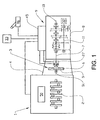
- the servo devices 40, 41, 42 and 43 are controlled by an electronic control unit 45 (see Figure 1), comprising a microcomputer, depending on signals fed into the control unit representing various engine and vehicle data comprising at least engine speed, vehicle speed, throttle pedal position and, where appropriate, engine brake on/off, when an electronic gear selector 46 coupled to the control unit 45 is in its automatic shifting position.
- an electronic gear selector 46 coupled to the control unit 45 is in its automatic shifting position.
- the speed is synchronized by precision control of the rotational speed of the engine 1.
- the disk clutch 3 is therefore engaged so that the rotational speed of the main shaft 10 and the rotational speed of the intermediate shaft 11 are adapted to a new ratio selected in the basic gearbox.
- the engine speed is regulated depending on the fuel quantity injected and the engine brake.
- the control unit 45 requests engine speed and/or engine torque from the engine control unit 50 which controls the fuel injection.
- the speed adaptation is effected by means of synchronizing rings.
- reference number 32 designates a coupling-dependent power take-off coupled to the intermediate shaft 11.
- the power take-off usually consists of a housing mounted on the side or rear end wall of the gearbox.
- an engaging and disengaging device By means of an engaging and disengaging device (not shown), the input shaft (not shown) of the power take-off 32 can be connected in a rotationally fixed manner to the intermediate shaft 11.
- the engaging and disengaging device of the power take-off 32 is controlled by the control unit 45.
- the control unit 45 receives a request for engagement and disengagement of the power take-off 32 from a device 33 for controlling the power take-off 32, which device 33 is connected to the control unit 45.
- the device 33 may be a control which is operated by the driver of the vehicle or an automatic arrangement which, via some form of sensor for example, senses a parameter change, which initiates engagement or disengagement of the power take-off.
- the power take-off 32 When the power take-off 32 is engaged, it is therefore driven by the engine 1 via the disk clutch 3, the split gear 12, 16 or 15, 17 and also the intermediate shaft 11.
- the power take-off 32 is usually equipped with one or more gearing possibilities on the at least one output shaft (not shown) of the power take-off. A desired unit to be driven is coupled to the output shaft of the power take-off 32.
- the method according to the invention makes possible engagement or disengagement of the power take-off when the vehicle is being driven. Therefore, the vehicle is in motion, a basic gear is engaged, and a split gear is engaged.
- the control unit 45 is, according to the invention, programmed so that, when the control unit 45 receives an input signal from the device 33 indicating that the power take-off 32 is to be engaged, the control unit 45 controls the engine torque so that the input shaft 7 of the gearbox 9 becomes torqueless or virtually torqueless.
- the control unit 45 disengages the disk clutch 3 and disengages the gear engaged in the basic gearbox so that the latter is in neutral position.
- the intermediate shaft 11 is therefore disengaged from the driving wheels of the vehicle.
- the gearbox can be equipped with a range gear stage (not shown) with a low gear position, a high gear position and a neutral position, which neutral position could alternatively be used in order to disengage the intermediate shaft 11 from the driving wheels.
- the control unit 45 waits until the rotational speed of the intermediate shaft 11 has been reduced to a low speed, typically 30 rpm or less in speed difference between the rotational speed of the intermediate shaft and of the input shaft of the power take-off 32.
- the reduction in the rotational speed of the intermediate shaft 11 can be accelerated, for example by means of an intermediate shaft brake 34 (shown only in Figure 2) arranged on the intermediate shaft 11.
- the braking function of the intermediate shaft brake 34 is controlled by the control unit 45.
- the control unit 45 engages the power take-off 32 by means of the engaging and disengaging device (not shown) of the power take-off.
- the control unit 45 then adapts the reengagement of the disk clutch 3 at a low engine speed. If the engaging and disengaging device of the power take-off is of the claw coupling type, the disk clutch 3 is slipped in in such a way that any gear tooth against gear tooth situation in the claw coupling is eliminated.
- the power take-off 32 is engaged, the disk clutch 3 is engaged fully, if appropriate via a torque control procedure.
- the control unit 45 is programmed so as, after engagement of the power take-off 32, to select the previously engaged gear in the basic gearbox.
- the control unit can adapt the gear selection in the basic gearbox taking account of the power take-off 32 and/or taking account of equipment (not shown) driven by the power take-off 32 and also the current or future state of the vehicle in other respects.
- the speed of the engine 1 is adapted to the gear which has been selected before the gear is engaged. When the basic gearbox is engaged and the engine 1 can therefore continue to drive the vehicle in a selected direction of motion, the engine torque is controlled to the driving torque requested by the driver.
- disengagement of the power take-off 32 takes place in a corresponding way by the control unit 45 first registering that disengagement via the device 33 is requested.
- the control unit 45 controls the output torque of the engine 1 so that the main shaft 10 becomes torqueless or virtually torqueless.
- the main shaft 10 is torqueless when the torque from the engine 1 is the same as the torque which drives the power take-off 32 taking account of ratio. Measurement of the torque at the power take-off is therefore necessary. This is effected most easily by arranging a torque transmitter on the input shaft of the power unit or on the output end of the intermediate shaft toward the power unit.
- the control unit 45 then puts the basic gearbox in neutral position so that the intermediate shaft 11 of the gearbox is disengaged from the driving wheels of the vehicle.
- control unit 45 can be programmed so that, if the split gear was in neutral position, the previously engaged split gear is selected or, if the disk clutch 3 was disengaged, the disk clutch 3 is engaged.
- the rotational speed of the engine is then controlled to synchronous speed with the selected gear in the basic gearbox.
- the control unit can be programmed so that the previous basic gear is selected or alternatively a new basic gear is selected along the current state of the vehicle, that is to say account can be taken of the fact that the power take-off is no longer engaged and/or of current or future vehicle speed and road topography. This can also apply to the selection of split gear and in the case of the engaging method for the power take-off.
- the engine torque is controlled to the driving torque requested by the driver.
- a torque transmitter 27 is arranged on the input shaft 7 of the gearbox 9.
- the control unit 45 can better control the output torque of the engine 1 and the extent of engagement of the disk clutch 3.
- the driver of the vehicle can advantageously be provided with feedback about the engaging/disengaging function of the power take-off by means of an indicator lamp and/or information on a display or another information device connected to the vehicle.
- the invention can also be applied to gearboxes without a split gear part.
- the invention can also be applied to gearboxes with one or more synchronized gears in the basic gearbox.
Landscapes
- Engineering & Computer Science (AREA)
- Chemical & Material Sciences (AREA)
- Combustion & Propulsion (AREA)
- Transportation (AREA)
- Mechanical Engineering (AREA)
- Automation & Control Theory (AREA)
- Control Of Transmission Device (AREA)
- Hydraulic Clutches, Magnetic Clutches, Fluid Clutches, And Fluid Joints (AREA)
- Control Of Driving Devices And Active Controlling Of Vehicle (AREA)
- Paper (AREA)
- Circuits Of Receivers In General (AREA)
- Sanitary Device For Flush Toilet (AREA)
- Agricultural Machines (AREA)
- Remote Monitoring And Control Of Power-Distribution Networks (AREA)
- Mechanical Operated Clutches (AREA)
Abstract
Description
- The present invention relates to a method for motor vehicles according to the preamble of
patent claims 1 and 6 below. The method relates to an automatic engaging/disengaging method for a coupling-dependent power take-off when the vehicle is in motion. - In order for it to be possible to handle the load on a truck effectively, load-handling equipment is necessary. The commonest examples of such equipment are tipping gear and cranes. Also common are hook loaders, refuse-handling units, rotating cement mixers, flushing units and air compressors for loading or unloading bulk loads.
- In order to utilize the driving power of the vehicle engine to drive the load-handling equipment as well, a power take-off is required. The driving power from the power take-off can be transmitted either mechanically via a propeller shaft or belts or hydraulically by a hydraulic pump being mounted on the power take-off.
- Power take-offs are divided into coupling-independent and coupling-dependent power take-offs. Coupling-dependent power take-offs are preferably used when the vehicle is stationary. The coupling-dependent power take-offs are mounted on the gearbox and are usually driven by the intermediate shaft of the gearbox. This means that the power take-off is coupling-dependent, that is to say the power take-off stops when the disk clutch between the engine and gearbox of the vehicle is disengaged. Depending on whether or not the gearbox is equipped with a split gear, the ratio between the engine and the power take-off can be influenced.
- Automatic gearboxes of the automated stage-geared gearbox type have become increasingly common in heavy-duty vehicles as microcomputer technology has developed further and made it possible, with a control computer and a number of actuators, for example servo motors, to precision-regulate engine speed, engagement and disengagement of an automated disk clutch between the engine and the gearbox and also the internal coupling means of the gearbox in such a way and in relation to one another so that gentle shifting is always obtained at the correct engine speed.
- The advantage of this type of automatic gearbox compared with a conventional automatic gearbox constructed with planetary gear stages and with a hydrodynamic torque converter on the input side is on the one hand that, especially as far as use in heavy-duty vehicles is concerned, it is simpler and more robust and can be manufactured at a considerably lower cost than the conventional automatic gearbox and on the other hand that it has higher efficiency, which means lower fuel consumption is possible.
- According to the known art for the abovementioned type of automated stage-geared gearbox, coupling-dependent power take-offs are suitable for load-handling equipment which is used when the vehicle is stationary or when the vehicle is driven in the starting gear, for example tipping units, cranes, hook loaders, pumps for emptying/filling from various containers and air compressors for loading or unloading bulk loads. As the power take-off loads the synchronization system when shifting takes place, it is not permitted for the power take-off to be engaged when shifts take place when the vehicle is being driven. The coupling-dependent power take-off is engaged when the vehicle is stationary and the disk clutch between the engine of the vehicle and the gearbox of the vehicle is disengaged. The gearbox is in its neutral position if the power take-off is to be used in a stationary vehicle or has a starting gear engaged if the power take-off is to be used during slow driving. When the disk clutch is engaged, the engine drives the power take-off, and the vehicle is driven in a starting gear if this is engaged. Disengagement of the power take-off is also effected when the vehicle is stationary and the disk clutch of the vehicle is disengaged.
- US6080081 discloses an example of a method for engaging a power take off, according to state of the art. Here, the vehicle has to be in a stand still condition and the transmission must have been put in a neutral position before a power take off engagement can be initiated.
- The driver of a vehicle with a coupling-dependent power take-off according to the state of the art is therefore limited to engaging and disengaging the power take-off only when the vehicle is stationary.
- A need therefore exists in a vehicle equipped with a coupling-dependent power take-off and an automated stage-geared gearbox to simplify operations for the driver of the vehicle when he wishes to use the coupling-dependent power take-off of the vehicle.
- The solution of the problem according to the invention as far as the method according to the invention is concerned is described in
patent claims 1 and 6. The other patent claims describe preferred embodiments and developments of the method according to the invention (claims 2 to 5, 7 to 11). - The method according to the invention describes an automatic engaging method and an automatic disengaging method for a coupling-dependent power take-off in a vehicle when the vehicle is in motion, which power take-off is driven by an engine, arranged in the vehicle, via an automated disk clutch which in turn is coupled to an automatic stage-geared gearbox in which a shaft for driving the power take-off is arranged. At least one control unit for controlling the gearbox, the disk clutch and the engine is arranged in the vehicle.
- In the case of the engaging method, the invention is characterized by the steps:
- the control unit registers that engagement of the power take-off is requested;
- the control unit disengages the disk clutch and puts the gearbox in neutral position so that the intermediate shaft of the gearbox is disengaged from the driving wheels of the vehicle;
- the control unit engages the power take-off.
- In the case of the disengaging method, the invention is characterized by the steps:
- the control unit registers that disengagement of the power take-off is requested;
- the control unit puts the gearbox in neutral position so that the intermediate shaft of the gearbox is disengaged from the driving wheels of the vehicle;
- the control unit disengages the disk clutch or puts a split gear in neutral position;
- the control unit disengages the power take-off.
- The advantage of the engaging/disengaging method according to the invention is that it is possible to engage and disengage a coupling-dependent power take-off even while driving the vehicle and irrespective of the gear engaged. It is easier for different configurations of units to be driven by the power take-off to be installed in the vehicle. This also includes units which, according to the state of the art, have to be driven by a coupling-independent power take-off. It is therefore possible with the aid of the invention to drive all types of unit by means of the coupling-dependent power take-off. The engagement or disengagement itself of the power take-off takes place completely automatically.
- In a first preferred embodiment of the engaging and disengaging method according to the invention, the control unit controls the output torque of the engine so that the input shaft of the gearbox becomes virtually torqueless before the control unit disengages the disk clutch. This method affords improved comfort.
- In a second embodiment of the engaging method according to the invention, the control unit ensures that the rotational speed of the intermediate shaft is reduced before engagement of the power take-off takes place. The advantage of the method according to the invention is that the engaging/disengaging device of the power take-off is subjected to smaller stresses and in this way the life of the device is prolonged.
- In a further preferred embodiment of the engaging and disengaging method according to the invention, the control unit measures the torque of the input shaft. The advantage of the method according to the invention is that the output torque of the engine and the extent of engagement of the disk clutch can be controlled more accurately.
- In another preferred embodiment of the disengaging method according to the invention, the control unit measures the torque at the power unit. By measuring the torque at the power unit, the output torque of the engine can be controlled so that the main shaft of the gearbox becomes torqueless or virtually torqueless, and the stresses on the coupling devices for the gear concerned in the basic gearbox when these are disengaged, that is to say when the gearbox is put in neutral position and the intermediate shaft is disengaged from the driving wheels of the vehicle, are therefore minimized. In a case where the torque take-off of the power take-off is relatively great, the load on the coupling devices is so great that neutral position is not obtained unless the torque can be controlled so that the main shaft of the gearbox becomes torqueless.
- Further embodiments of the invention emerge from the dependent patent claims.
- The present invention will be described in greater detail below with reference to the accompanying drawings, which, for the purpose of exemplification, show further preferred embodiments of the invention and also the technical background.
- Figure 1 shows a diagrammatic representation of an internal combustion engine with adjacent clutch and gearbox with a power take-off.
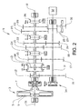
- Figure 2 shows the clutch and the gearbox in Figure 1 on enlarged scale.
- In Figure 1, reference number 1 designates a six-cylinder internal combustion engine, for example a diesel engine, the
crankshaft 2 of which is coupled to a single-plate dry disk clutch, designated generally byreference number 3, which is enclosed in aclutch case 4. Thecrankshaft 2 is, via theoutput shaft 51 of the engine, which shaft is connected to the flywheel (not shown), connected non-rotatably to theclutch housing 5 of theclutch 3, while itsplate 6 is connected non-rotatably to aninput shaft 7 which is mounted rotatably in thecasing 8 of a gearbox designated generally byreference number 9. Amain shaft 10 and anintermediate shaft 11 are also mounted rotatably in thecasing 8. - As can be seen most clearly from Figure 2, a
gearwheel 12 is mounted rotatably on theinput shaft 7 and is lockable on the shaft by means of acoupling sleeve 13 which is provided with synchronizing means and is mounted non-rotatably but axially displaceably on ahub 14 connected non-rotatably to theinput shaft 7. By means of thecoupling sleeve 13, agearwheel 15 mounted rotatably on themain shaft 10 is also lockable relative to theinput shaft 7. With thecoupling sleeve 13 in a central position, both thegearwheels shafts 7 and, respectively, 10. Thegearwheels gearwheels 16 and, respectively, 17 which are connected non-rotatably to theintermediate shaft 11. Arranged in a rotationally fixed manner on theintermediate shaft 11 arefurther gearwheels gearwheels main shaft 10 and are lockable on the main shaft by means ofcoupling sleeves 24 and, respectively, 25 which, in the illustrative embodiment shown, do not have synchronizing devices. Afurther gearwheel 28 is mounted rotatably on themain shaft 10 and engages with anintermediate gearwheel 30 which is mounted rotatably on aseparate shaft 29 and in turn engages with theintermediate shaft gearwheel 20. Thegearwheel 28 is lockable on its shaft by means of acoupling sleeve 26. - The gearwheel pairs 12, 16 and 15, 17 and the
coupling sleeve 13 form a synchronized split gear with a low gear stage LS and a high gear stage HS. Thegearwheel pair gearwheels main shaft 10 can be connected directly to a propeller shaft (not shown) which conveys the driving power out to the driving wheels (not shown). An alternative is for the output end of themain shaft 10 to be connected to a range gear stage (not shown) which in turn is connected to the propeller shaft. - The
coupling sleeves coupling sleeves coupling sleeve 26 has one gear position and a neutral position N. The displacement of the coupling sleeves is brought about byrespective servo devices - The
servo devices electronic gear selector 46 coupled to thecontrol unit 45 is in its automatic shifting position. When the selector is in the position for manual shifting, shifting takes place at the command of the driver via thegear selector 46. - When shifting of the unsynchronized gears takes place, the speed is synchronized by precision control of the rotational speed of the engine 1. The
disk clutch 3 is therefore engaged so that the rotational speed of themain shaft 10 and the rotational speed of theintermediate shaft 11 are adapted to a new ratio selected in the basic gearbox. The engine speed is regulated depending on the fuel quantity injected and the engine brake. Thecontrol unit 45 requests engine speed and/or engine torque from theengine control unit 50 which controls the fuel injection. When shifting of synchronized gears takes place, the speed adaptation is effected by means of synchronizing rings. - In Figures 1 and 2,
reference number 32 designates a coupling-dependent power take-off coupled to theintermediate shaft 11. The power take-off usually consists of a housing mounted on the side or rear end wall of the gearbox. By means of an engaging and disengaging device (not shown), the input shaft (not shown) of the power take-off 32 can be connected in a rotationally fixed manner to theintermediate shaft 11. The engaging and disengaging device of the power take-off 32 is controlled by thecontrol unit 45. Thecontrol unit 45 receives a request for engagement and disengagement of the power take-off 32 from adevice 33 for controlling the power take-off 32, whichdevice 33 is connected to thecontrol unit 45. Thedevice 33 may be a control which is operated by the driver of the vehicle or an automatic arrangement which, via some form of sensor for example, senses a parameter change, which initiates engagement or disengagement of the power take-off. When the power take-off 32 is engaged, it is therefore driven by the engine 1 via thedisk clutch 3, thesplit gear intermediate shaft 11. The power take-off 32 is usually equipped with one or more gearing possibilities on the at least one output shaft (not shown) of the power take-off. A desired unit to be driven is coupled to the output shaft of the power take-off 32. - The method according to the invention makes possible engagement or disengagement of the power take-off when the vehicle is being driven. Therefore, the vehicle is in motion, a basic gear is engaged, and a split gear is engaged. In this vehicle state, the
control unit 45 is, according to the invention, programmed so that, when thecontrol unit 45 receives an input signal from thedevice 33 indicating that the power take-off 32 is to be engaged, thecontrol unit 45 controls the engine torque so that theinput shaft 7 of thegearbox 9 becomes torqueless or virtually torqueless. - When the
input shaft 7 is torqueless or virtually torqueless, thecontrol unit 45 disengages thedisk clutch 3 and disengages the gear engaged in the basic gearbox so that the latter is in neutral position. Theintermediate shaft 11 is therefore disengaged from the driving wheels of the vehicle. In an alternative embodiment, the gearbox can be equipped with a range gear stage (not shown) with a low gear position, a high gear position and a neutral position, which neutral position could alternatively be used in order to disengage theintermediate shaft 11 from the driving wheels. After disengagement of theintermediate shaft 11, thecontrol unit 45 waits until the rotational speed of theintermediate shaft 11 has been reduced to a low speed, typically 30 rpm or less in speed difference between the rotational speed of the intermediate shaft and of the input shaft of the power take-off 32. The reduction in the rotational speed of theintermediate shaft 11 can be accelerated, for example by means of an intermediate shaft brake 34 (shown only in Figure 2) arranged on theintermediate shaft 11. The braking function of theintermediate shaft brake 34 is controlled by thecontrol unit 45. - In the next step, the
control unit 45 engages the power take-off 32 by means of the engaging and disengaging device (not shown) of the power take-off. Thecontrol unit 45 then adapts the reengagement of thedisk clutch 3 at a low engine speed. If the engaging and disengaging device of the power take-off is of the claw coupling type, thedisk clutch 3 is slipped in in such a way that any gear tooth against gear tooth situation in the claw coupling is eliminated. When the power take-off 32 is engaged, thedisk clutch 3 is engaged fully, if appropriate via a torque control procedure. - According to an advantageous embodiment of the invention, the
control unit 45 is programmed so as, after engagement of the power take-off 32, to select the previously engaged gear in the basic gearbox. Alternatively, the control unit can adapt the gear selection in the basic gearbox taking account of the power take-off 32 and/or taking account of equipment (not shown) driven by the power take-off 32 and also the current or future state of the vehicle in other respects. The speed of the engine 1 is adapted to the gear which has been selected before the gear is engaged. When the basic gearbox is engaged and the engine 1 can therefore continue to drive the vehicle in a selected direction of motion, the engine torque is controlled to the driving torque requested by the driver. - According to the invention, disengagement of the power take-
off 32 takes place in a corresponding way by thecontrol unit 45 first registering that disengagement via thedevice 33 is requested. Thecontrol unit 45 then controls the output torque of the engine 1 so that themain shaft 10 becomes torqueless or virtually torqueless. Themain shaft 10 is torqueless when the torque from the engine 1 is the same as the torque which drives the power take-off 32 taking account of ratio. Measurement of the torque at the power take-off is therefore necessary. This is effected most easily by arranging a torque transmitter on the input shaft of the power unit or on the output end of the intermediate shaft toward the power unit. Thecontrol unit 45 then puts the basic gearbox in neutral position so that theintermediate shaft 11 of the gearbox is disengaged from the driving wheels of the vehicle. This can take place by means of all the gears in the basic gearbox being in neutral position or alternatively, as mentioned above, a range gear stage (not shown) being put in its neutral position. The engine 1 is then controlled, if possible, so that the torque on theinput shaft 7 of thegearbox 9 becomes torqueless or virtually torqueless. Thecontrol unit 45 then disengages the intermediate shaft from the engine 1. This is effected by thedisk clutch 3 being disengaged or alternatively thesplit gear part intermediate shaft 11 is completely disengaged from the engine 1 and driving wheels of the vehicle, thecontrol unit 45 disengages the power take-off 32 by means of the engaging and disengaging device of the power take-off 32. For the next step, thecontrol unit 45 can be programmed so that, if the split gear was in neutral position, the previously engaged split gear is selected or, if thedisk clutch 3 was disengaged, thedisk clutch 3 is engaged. The rotational speed of the engine is then controlled to synchronous speed with the selected gear in the basic gearbox. The control unit can be programmed so that the previous basic gear is selected or alternatively a new basic gear is selected along the current state of the vehicle, that is to say account can be taken of the fact that the power take-off is no longer engaged and/or of current or future vehicle speed and road topography. This can also apply to the selection of split gear and in the case of the engaging method for the power take-off. When the basic gearbox is engaged and the engine 1 can therefore continue to drive the vehicle in a selected direction of motion, the engine torque is controlled to the driving torque requested by the driver. - In another embodiment of the invention, a
torque transmitter 27 is arranged on theinput shaft 7 of thegearbox 9. By means of atorque transmitter 27 arranged on theinput shaft 7, thecontrol unit 45 can better control the output torque of the engine 1 and the extent of engagement of thedisk clutch 3. - In an embodiment of the invention, the driver of the vehicle can advantageously be provided with feedback about the engaging/disengaging function of the power take-off by means of an indicator lamp and/or information on a display or another information device connected to the vehicle.
- The invention can also be applied to gearboxes without a split gear part.
- The invention can also be applied to gearboxes with one or more synchronized gears in the basic gearbox.
- The invention is not to be considered as being limited to the illustrative embodiments described above, but a number of further variants and modifications are conceivable within the scope of the patent claims below.
Claims (11)
- An automatic engaging method for a coupling-dependent power take-off (32) in a vehicle when the vehicle is in motion, which power take-off (32) is driven by an engine (1), arranged in the vehicle, via an automated disk clutch (3) which in turn is coupled to an automatic stage-geared gearbox (9) in which an intermediate shaft (11) for driving the power take-off (32) is arranged, where at least one control unit (45) controls the gearbox (9), the disk clutch (3) and the engine (1), the engaging method being characterized by the steps:- the control unit (45) registers that engagement of the power take-off (32) is requested;- the control unit (45) disengages the disk clutch (3) and puts the gearbox (9) in neutral position so that the intermediate shaft (11) of the gearbox (9) is disengaged from the driving wheels of the vehicle;- the control unit (45) engages the power take-off (32).
- The automatic engaging method as claimed in claim 1, where the method is further characterized by the step that, before the control unit (45) disengages the disk clutch (3), the control unit (45) controls the output torque of the engine (1) so that the input shaft (7) of the gearbox (9) becomes virtually torqueless.
- The automatic engaging method as claimed in claim 2, where the method is further characterized by the step that the control unit (45) measures the torque of the input shaft (7).
- The automatic engaging method as claimed in any one of the preceding claims, where the method is further characterized by the step that, before engagement of the power take-off (32) takes place, the control unit (45) ensures that the rotational speed of the intermediate shaft (11) is reduced.
- The automatic engaging method as claimed in any one of the preceding claims, where the method is further characterized by the steps that, after engagement of the power take-off (32), the control unit (45) couples the disk clutch (3) together and engages a previously selected or a newly selected total ratio in the gearbox (9) after adaptation of the speed of the engine (1) to the selected gear.
- An automatic disengaging method for a coupling-dependent power take-off (32) in a vehicle when the vehicle is in motion, which power take-off (32) is driven by an engine (1), arranged in the vehicle, via an automated disk clutch (3) which in turn is coupled to an automatic stage-geared gearbox (9) in which an intermediate shaft (11) for driving the power take-off (32) is arranged, where at least one control unit (45) controls the gearbox (9), the disk clutch (3) and the engine (1), the disengaging method being characterized by the steps:- the control unit (45) registers that disengagement of the power take-off (32) is requested;- the control unit (45) puts the gearbox (9) in neutral position so that the intermediate shaft (11) of the gearbox (9) is disengaged from the driving wheels of the vehicle;- the control unit (45) disengages the disk clutch (3) or puts a split gear (12, 16, 15, 17) in neutral position;- the control unit (45) disengages the power take-off (32).
- The automatic disengaging method as claimed in claim 6, where the method is further characterized by the step that the control unit (45) measures the torque at the power unit (32).
- The automatic disengaging method as claimed in one of claims 6 or 7, where the method is further characterized by the step that, before the control unit (45) puts the gearbox (9) in neutral position so that the intermediate shaft (11) of the gearbox (9) is disengaged from the driving wheels of the vehicle, the control unit (45) controls the output torque of the engine (1) so that the main shaft (10) of the gearbox (9) becomes torqueless or virtually torqueless.
- The automatic disengaging method as claimed in any one of claims 6 to 8, where the method is further characterized by the step that, before the control unit (45) disengages the disk clutch (3) or puts a split gear (12, 16, 15, 17) in neutral position, the control unit (45) controls the speed of the engine (1) so that the input shaft (7) of the gearbox (9) becomes virtually torqueless.
- The automatic disengaging method as claimed in any one of claims 6 to 9, where the method is further characterized by the step that, after disengagement of the power take-off (32), the control unit (45) couples the disk clutch (3) together or engages a split gear (12, 16, 15, 17) and engages a previously selected or a newly selected total ratio in the gearbox (9).
- The automatic disengaging method as claimed in any one of claims 6 to 10, where the method is further characterized by the step that the control unit (45) measures the torque of the input shaft (7).
Applications Claiming Priority (3)
| Application Number | Priority Date | Filing Date | Title |
|---|---|---|---|
| SE0203305 | 2002-11-07 | ||
| SE0203305A SE524144C2 (en) | 2002-11-07 | 2002-11-07 | Automatic switch-on / switch-off method and device for controlling a switch-dependent power take-off |
| PCT/SE2003/001388 WO2004041576A1 (en) | 2002-11-07 | 2003-09-08 | An automatic engaging/disengaging method and a device for controlling a coupling-dependent power take-off |
Publications (2)
| Publication Number | Publication Date |
|---|---|
| EP1567384A1 EP1567384A1 (en) | 2005-08-31 |
| EP1567384B1 true EP1567384B1 (en) | 2007-05-09 |
Family
ID=20289509
Family Applications (1)
| Application Number | Title | Priority Date | Filing Date |
|---|---|---|---|
| EP03810724A Expired - Lifetime EP1567384B1 (en) | 2002-11-07 | 2003-09-08 | An automatic engaging/disengaging method and a device for controlling a coupling-dependent power take-off |
Country Status (6)
| Country | Link |
|---|---|
| EP (1) | EP1567384B1 (en) |
| AT (1) | ATE361853T1 (en) |
| AU (1) | AU2003257752A1 (en) |
| DE (1) | DE60313799T2 (en) |
| SE (1) | SE524144C2 (en) |
| WO (1) | WO2004041576A1 (en) |
Cited By (1)
| Publication number | Priority date | Publication date | Assignee | Title |
|---|---|---|---|---|
| CN108238037A (en) * | 2016-12-23 | 2018-07-03 | 丰田自动车株式会社 | The control device of hybrid vehicle |
Families Citing this family (5)
| Publication number | Priority date | Publication date | Assignee | Title |
|---|---|---|---|---|
| EP2066519B1 (en) | 2006-09-18 | 2011-07-27 | Volvo Lastvagnar AB | .an automatic disengaging/engaging method of a clutch dependent power take-off |
| DE102008040757A1 (en) * | 2008-07-28 | 2010-02-04 | Zf Friedrichshafen Ag | Method and arrangement for coupling and uncoupling a power take-off in an automated transmission |
| DE102010002724A1 (en) * | 2010-03-10 | 2011-09-15 | Zf Friedrichshafen Ag | Method for operating a drive train |
| GB2505294A (en) * | 2013-06-27 | 2014-02-26 | Daimler Ag | Control method for power take off |
| DE102013215249A1 (en) * | 2013-08-02 | 2015-02-05 | Zf Friedrichshafen Ag | Method for disconnecting a power take-off of a motor vehicle transmission during a journey of a motor vehicle |
Family Cites Families (4)
| Publication number | Priority date | Publication date | Assignee | Title |
|---|---|---|---|---|
| US5299129A (en) * | 1990-03-26 | 1994-03-29 | Aisin Seiki Kabushiki Kaisha | PTO control apparatus for vehicular automatic transmission |
| US5611751A (en) * | 1995-09-26 | 1997-03-18 | Caterpillar Inc. | Engine speed control and method for operating same |
| DE19708929A1 (en) * | 1997-03-05 | 1998-09-10 | Zahnradfabrik Friedrichshafen | Control of power take-offs in automated vehicle transmissions |
| DE10059708A1 (en) * | 2000-01-12 | 2001-07-19 | Mannesmann Sachs Ag | Controller for motor vehicle with automatic gearbox detects drive train torque change, activates suppression circuit to at least delay auxiliary assembly switch on or off process |
-
2002
- 2002-11-07 SE SE0203305A patent/SE524144C2/en not_active IP Right Cessation
-
2003
- 2003-09-08 EP EP03810724A patent/EP1567384B1/en not_active Expired - Lifetime
- 2003-09-08 WO PCT/SE2003/001388 patent/WO2004041576A1/en active IP Right Grant
- 2003-09-08 AU AU2003257752A patent/AU2003257752A1/en not_active Abandoned
- 2003-09-08 DE DE60313799T patent/DE60313799T2/en not_active Expired - Lifetime
- 2003-09-08 AT AT03810724T patent/ATE361853T1/en not_active IP Right Cessation
Cited By (1)
| Publication number | Priority date | Publication date | Assignee | Title |
|---|---|---|---|---|
| CN108238037A (en) * | 2016-12-23 | 2018-07-03 | 丰田自动车株式会社 | The control device of hybrid vehicle |
Also Published As
| Publication number | Publication date |
|---|---|
| DE60313799D1 (en) | 2007-06-21 |
| WO2004041576A1 (en) | 2004-05-21 |
| AU2003257752A1 (en) | 2004-06-07 |
| EP1567384A1 (en) | 2005-08-31 |
| ATE361853T1 (en) | 2007-06-15 |
| SE524144C2 (en) | 2004-07-06 |
| SE0203305L (en) | 2004-05-08 |
| SE0203305D0 (en) | 2002-11-07 |
| DE60313799T2 (en) | 2008-01-24 |
Similar Documents
| Publication | Publication Date | Title |
|---|---|---|
| EP1587703B1 (en) | Gearshift procedure for vehicles with engaged clutch-dependent power take-off | |
| US7487025B2 (en) | Automatic gearshifting process for a vehicle with engaged coupling-dependent power take off and automatic disengagement process of a coupling-dependent power take off | |
| US7347804B2 (en) | Automatic engaging/disengaging method of a coupling-independent power take-off | |
| US7357753B2 (en) | Method for regulating the rotational speed of a clutch-independent power take-off | |
| US7278950B2 (en) | Stage-geared gearbox for motor vehicles | |
| US7077024B2 (en) | Procedure for upshifting gear in a motor vehicle and a power plant unit for a motor vehicle | |
| EP1507678B1 (en) | Procedure for upshifting gear in a motor vehicle and a power plant unit for a motor vehicle | |
| US5186291A (en) | Transmission for a vehicle | |
| EP1567384B1 (en) | An automatic engaging/disengaging method and a device for controlling a coupling-dependent power take-off | |
| EP1549523B1 (en) | An automatic engaging/disengaging method of a coupling-dependent power take-off | |
| US20060162475A1 (en) | Drive means for motor vehicles | |
| EP2286116B1 (en) | Method and device for securing lubrication of an automated manual transmission in a vehicle | |
| EP1532014B1 (en) | Drive means for motor vehicles | |
| WO2003095258A1 (en) | Drive means for motor vehicles |
Legal Events
| Date | Code | Title | Description |
|---|---|---|---|
| PUAI | Public reference made under article 153(3) epc to a published international application that has entered the european phase |
Free format text: ORIGINAL CODE: 0009012 |
|
| 17P | Request for examination filed |
Effective date: 20050607 |
|
| AK | Designated contracting states |
Kind code of ref document: A1 Designated state(s): AT BE BG CH CY CZ DE DK EE ES FI FR GB GR HU IE IT LI LU MC NL PT RO SE SI SK TR |
|
| AX | Request for extension of the european patent |
Extension state: AL LT LV MK |
|
| DAX | Request for extension of the european patent (deleted) | ||
| GRAP | Despatch of communication of intention to grant a patent |
Free format text: ORIGINAL CODE: EPIDOSNIGR1 |
|
| RIC1 | Information provided on ipc code assigned before grant |
Ipc: B60K 17/28 20060101AFI20061113BHEP Ipc: B60W 10/02 20060101ALI20061113BHEP Ipc: F16H 63/40 20060101ALI20061113BHEP |
|
| GRAS | Grant fee paid |
Free format text: ORIGINAL CODE: EPIDOSNIGR3 |
|
| GRAA | (expected) grant |
Free format text: ORIGINAL CODE: 0009210 |
|
| AK | Designated contracting states |
Kind code of ref document: B1 Designated state(s): AT BE BG CH CY CZ DE DK EE ES FI FR GB GR HU IE IT LI LU MC NL PT RO SE SI SK TR |
|
| PG25 | Lapsed in a contracting state [announced via postgrant information from national office to epo] |
Ref country code: CH Free format text: LAPSE BECAUSE OF FAILURE TO SUBMIT A TRANSLATION OF THE DESCRIPTION OR TO PAY THE FEE WITHIN THE PRESCRIBED TIME-LIMIT Effective date: 20070509 Ref country code: LI Free format text: LAPSE BECAUSE OF FAILURE TO SUBMIT A TRANSLATION OF THE DESCRIPTION OR TO PAY THE FEE WITHIN THE PRESCRIBED TIME-LIMIT Effective date: 20070509 Ref country code: FI Free format text: LAPSE BECAUSE OF FAILURE TO SUBMIT A TRANSLATION OF THE DESCRIPTION OR TO PAY THE FEE WITHIN THE PRESCRIBED TIME-LIMIT Effective date: 20070509 |
|
| REG | Reference to a national code |
Ref country code: GB Ref legal event code: FG4D |
|
| REG | Reference to a national code |
Ref country code: CH Ref legal event code: EP |
|
| REG | Reference to a national code |
Ref country code: IE Ref legal event code: FG4D |
|
| REF | Corresponds to: |
Ref document number: 60313799 Country of ref document: DE Date of ref document: 20070621 Kind code of ref document: P |
|
| PG25 | Lapsed in a contracting state [announced via postgrant information from national office to epo] |
Ref country code: SE Free format text: LAPSE BECAUSE OF FAILURE TO SUBMIT A TRANSLATION OF THE DESCRIPTION OR TO PAY THE FEE WITHIN THE PRESCRIBED TIME-LIMIT Effective date: 20070809 |
|
| PG25 | Lapsed in a contracting state [announced via postgrant information from national office to epo] |
Ref country code: ES Free format text: LAPSE BECAUSE OF FAILURE TO SUBMIT A TRANSLATION OF THE DESCRIPTION OR TO PAY THE FEE WITHIN THE PRESCRIBED TIME-LIMIT Effective date: 20070820 |
|
| ET | Fr: translation filed | ||
| NLV1 | Nl: lapsed or annulled due to failure to fulfill the requirements of art. 29p and 29m of the patents act | ||
| REG | Reference to a national code |
Ref country code: CH Ref legal event code: PL |
|
| PG25 | Lapsed in a contracting state [announced via postgrant information from national office to epo] |
Ref country code: AT Free format text: LAPSE BECAUSE OF FAILURE TO SUBMIT A TRANSLATION OF THE DESCRIPTION OR TO PAY THE FEE WITHIN THE PRESCRIBED TIME-LIMIT Effective date: 20070509 |
|
| PG25 | Lapsed in a contracting state [announced via postgrant information from national office to epo] |
Ref country code: BE Free format text: LAPSE BECAUSE OF FAILURE TO SUBMIT A TRANSLATION OF THE DESCRIPTION OR TO PAY THE FEE WITHIN THE PRESCRIBED TIME-LIMIT Effective date: 20070509 |
|
| PG25 | Lapsed in a contracting state [announced via postgrant information from national office to epo] |
Ref country code: NL Free format text: LAPSE BECAUSE OF FAILURE TO SUBMIT A TRANSLATION OF THE DESCRIPTION OR TO PAY THE FEE WITHIN THE PRESCRIBED TIME-LIMIT Effective date: 20070509 Ref country code: PT Free format text: LAPSE BECAUSE OF FAILURE TO SUBMIT A TRANSLATION OF THE DESCRIPTION OR TO PAY THE FEE WITHIN THE PRESCRIBED TIME-LIMIT Effective date: 20071009 Ref country code: SI Free format text: LAPSE BECAUSE OF FAILURE TO SUBMIT A TRANSLATION OF THE DESCRIPTION OR TO PAY THE FEE WITHIN THE PRESCRIBED TIME-LIMIT Effective date: 20070509 Ref country code: CZ Free format text: LAPSE BECAUSE OF FAILURE TO SUBMIT A TRANSLATION OF THE DESCRIPTION OR TO PAY THE FEE WITHIN THE PRESCRIBED TIME-LIMIT Effective date: 20070509 Ref country code: DK Free format text: LAPSE BECAUSE OF FAILURE TO SUBMIT A TRANSLATION OF THE DESCRIPTION OR TO PAY THE FEE WITHIN THE PRESCRIBED TIME-LIMIT Effective date: 20070509 Ref country code: BG Free format text: LAPSE BECAUSE OF FAILURE TO SUBMIT A TRANSLATION OF THE DESCRIPTION OR TO PAY THE FEE WITHIN THE PRESCRIBED TIME-LIMIT Effective date: 20070809 |
|
| PG25 | Lapsed in a contracting state [announced via postgrant information from national office to epo] |
Ref country code: SK Free format text: LAPSE BECAUSE OF FAILURE TO SUBMIT A TRANSLATION OF THE DESCRIPTION OR TO PAY THE FEE WITHIN THE PRESCRIBED TIME-LIMIT Effective date: 20070509 |
|
| PLBE | No opposition filed within time limit |
Free format text: ORIGINAL CODE: 0009261 |
|
| STAA | Information on the status of an ep patent application or granted ep patent |
Free format text: STATUS: NO OPPOSITION FILED WITHIN TIME LIMIT |
|
| 26N | No opposition filed |
Effective date: 20080212 |
|
| PG25 | Lapsed in a contracting state [announced via postgrant information from national office to epo] |
Ref country code: IT Free format text: LAPSE BECAUSE OF FAILURE TO SUBMIT A TRANSLATION OF THE DESCRIPTION OR TO PAY THE FEE WITHIN THE PRESCRIBED TIME-LIMIT Effective date: 20070509 Ref country code: MC Free format text: LAPSE BECAUSE OF NON-PAYMENT OF DUE FEES Effective date: 20070930 Ref country code: GR Free format text: LAPSE BECAUSE OF FAILURE TO SUBMIT A TRANSLATION OF THE DESCRIPTION OR TO PAY THE FEE WITHIN THE PRESCRIBED TIME-LIMIT Effective date: 20070810 |
|
| GBPC | Gb: european patent ceased through non-payment of renewal fee |
Effective date: 20070908 |
|
| PG25 | Lapsed in a contracting state [announced via postgrant information from national office to epo] |
Ref country code: RO Free format text: LAPSE BECAUSE OF FAILURE TO SUBMIT A TRANSLATION OF THE DESCRIPTION OR TO PAY THE FEE WITHIN THE PRESCRIBED TIME-LIMIT Effective date: 20070509 |
|
| PG25 | Lapsed in a contracting state [announced via postgrant information from national office to epo] |
Ref country code: IE Free format text: LAPSE BECAUSE OF NON-PAYMENT OF DUE FEES Effective date: 20070910 |
|
| PG25 | Lapsed in a contracting state [announced via postgrant information from national office to epo] |
Ref country code: GB Free format text: LAPSE BECAUSE OF NON-PAYMENT OF DUE FEES Effective date: 20070908 |
|
| PG25 | Lapsed in a contracting state [announced via postgrant information from national office to epo] |
Ref country code: EE Free format text: LAPSE BECAUSE OF FAILURE TO SUBMIT A TRANSLATION OF THE DESCRIPTION OR TO PAY THE FEE WITHIN THE PRESCRIBED TIME-LIMIT Effective date: 20070509 |
|
| PG25 | Lapsed in a contracting state [announced via postgrant information from national office to epo] |
Ref country code: CY Free format text: LAPSE BECAUSE OF FAILURE TO SUBMIT A TRANSLATION OF THE DESCRIPTION OR TO PAY THE FEE WITHIN THE PRESCRIBED TIME-LIMIT Effective date: 20070509 |
|
| PG25 | Lapsed in a contracting state [announced via postgrant information from national office to epo] |
Ref country code: LU Free format text: LAPSE BECAUSE OF NON-PAYMENT OF DUE FEES Effective date: 20070908 |
|
| PG25 | Lapsed in a contracting state [announced via postgrant information from national office to epo] |
Ref country code: HU Free format text: LAPSE BECAUSE OF FAILURE TO SUBMIT A TRANSLATION OF THE DESCRIPTION OR TO PAY THE FEE WITHIN THE PRESCRIBED TIME-LIMIT Effective date: 20071110 Ref country code: TR Free format text: LAPSE BECAUSE OF FAILURE TO SUBMIT A TRANSLATION OF THE DESCRIPTION OR TO PAY THE FEE WITHIN THE PRESCRIBED TIME-LIMIT Effective date: 20070509 |
|
| REG | Reference to a national code |
Ref country code: FR Ref legal event code: PLFP Year of fee payment: 13 |
|
| REG | Reference to a national code |
Ref country code: FR Ref legal event code: PLFP Year of fee payment: 14 |
|
| REG | Reference to a national code |
Ref country code: FR Ref legal event code: PLFP Year of fee payment: 15 |
|
| REG | Reference to a national code |
Ref country code: FR Ref legal event code: PLFP Year of fee payment: 16 |
|
| PGFP | Annual fee paid to national office [announced via postgrant information from national office to epo] |
Ref country code: FR Payment date: 20190926 Year of fee payment: 17 |
|
| PGFP | Annual fee paid to national office [announced via postgrant information from national office to epo] |
Ref country code: DE Payment date: 20191129 Year of fee payment: 17 |
|
| REG | Reference to a national code |
Ref country code: DE Ref legal event code: R119 Ref document number: 60313799 Country of ref document: DE |
|
| PG25 | Lapsed in a contracting state [announced via postgrant information from national office to epo] |
Ref country code: DE Free format text: LAPSE BECAUSE OF NON-PAYMENT OF DUE FEES Effective date: 20210401 Ref country code: FR Free format text: LAPSE BECAUSE OF NON-PAYMENT OF DUE FEES Effective date: 20200930 |