EP1567307B1 - Split nosepiece for driving collated screws - Google Patents
Split nosepiece for driving collated screws Download PDFInfo
- Publication number
- EP1567307B1 EP1567307B1 EP03775008.0A EP03775008A EP1567307B1 EP 1567307 B1 EP1567307 B1 EP 1567307B1 EP 03775008 A EP03775008 A EP 03775008A EP 1567307 B1 EP1567307 B1 EP 1567307B1
- Authority
- EP
- European Patent Office
- Prior art keywords
- strap
- screw
- screws
- guideway
- nose portion
- Prior art date
- Legal status (The legal status is an assumption and is not a legal conclusion. Google has not performed a legal analysis and makes no representation as to the accuracy of the status listed.)
- Expired - Lifetime
Links
- 230000007246 mechanism Effects 0.000 claims description 28
- 239000004033 plastic Substances 0.000 claims description 15
- 230000004913 activation Effects 0.000 claims description 5
- 238000006073 displacement reaction Methods 0.000 claims description 4
- 230000000295 complement effect Effects 0.000 description 11
- 230000008901 benefit Effects 0.000 description 4
- 230000006835 compression Effects 0.000 description 4
- 238000007906 compression Methods 0.000 description 4
- 230000000694 effects Effects 0.000 description 3
- 230000003993 interaction Effects 0.000 description 3
- 230000004048 modification Effects 0.000 description 3
- 238000012986 modification Methods 0.000 description 3
- 239000004677 Nylon Substances 0.000 description 2
- 238000010276 construction Methods 0.000 description 2
- 210000003811 finger Anatomy 0.000 description 2
- 239000000463 material Substances 0.000 description 2
- 239000002184 metal Substances 0.000 description 2
- 229920001778 nylon Polymers 0.000 description 2
- 210000003813 thumb Anatomy 0.000 description 2
- 230000003213 activating effect Effects 0.000 description 1
- 230000000903 blocking effect Effects 0.000 description 1
- 230000008859 change Effects 0.000 description 1
- 238000001125 extrusion Methods 0.000 description 1
- 238000009408 flooring Methods 0.000 description 1
- 238000002347 injection Methods 0.000 description 1
- 239000007924 injection Substances 0.000 description 1
- 239000003562 lightweight material Substances 0.000 description 1
- 238000000034 method Methods 0.000 description 1
- 239000002991 molded plastic Substances 0.000 description 1
- 230000008569 process Effects 0.000 description 1
- 230000000087 stabilizing effect Effects 0.000 description 1
Images


Classifications
-
- B—PERFORMING OPERATIONS; TRANSPORTING
- B25—HAND TOOLS; PORTABLE POWER-DRIVEN TOOLS; MANIPULATORS
- B25B—TOOLS OR BENCH DEVICES NOT OTHERWISE PROVIDED FOR, FOR FASTENING, CONNECTING, DISENGAGING OR HOLDING
- B25B23/00—Details of, or accessories for, spanners, wrenches, screwdrivers
- B25B23/02—Arrangements for handling screws or nuts
- B25B23/04—Arrangements for handling screws or nuts for feeding screws or nuts
- B25B23/045—Arrangements for handling screws or nuts for feeding screws or nuts using disposable strips or discs carrying the screws or nuts
Definitions
- This invention relates to autofeed screwdrivers and, more particularly, to an autofeed screwdriver adapted to drive a variety of different size screws collated in a screwstrip.
- Such an apparatus is known from US 5826468A1 .
- Previously known autofeed screwdrivers suffer the disadvantage that they must be adjusted or modified so as to be able to drive screws of considerably varying lengths.
- Previously known autofeed screwdrivers utilize a number of different mechanisms to hold the screw and/or strap of a screwstrip so as to locate a screw to be driven and supporting the spent strap on a forward surface of an exitway.
- previously known devices suffer the disadvantage that they do not utilize a combination of these features in a tool adapted to drive screws of different lengths.
- the present invention provides a combination comprising a screwdriver assembly, threaded screws from a screwstrip and a screwstrip as shown in claim 1.
- the workpiece engaging nose body includes a nose portion and a rear portion with the nose portion slidably mounted on the rear portion for movement rearwardly when the nose is urged into a workpiece to drive a screw.
- An exitway is defined between the nose portion and rear portion through which spent strap from which screws have been driven exit the nose body.
- the nose portion slides rearwardly to engage the strap in the exitway and move it rearwardly into engagement with the rear portion in the exitway.
- the strap is preferably "pinched" or “clamped” in the exitway between the nose portion and rear portion to assist in locating a screw to be driven from the nose body.
- the nose body is preferably used in combination with a screwstrip having a strap with rear surface disposed at a constant distance forwardly of the heads of the screws such that the rear surface of the strap may be engaged by the rear portion in the exitway to accurately locate the screwstrip in the nose body.
- the nose portion may also carry, near a forwardmost surface of the nose portion to engage a workpiece, a rearwardly directed surface which is adapted when the nose portion moves rearwardly relative the rear portion to engage a tip of a screw next to the screw to be driven and "sandwich" the next screw between the nose portion and the rear portion to hold the screwstrip in a desired position to facilitate driving a screw.
- the nose body is adapted to drive screws of considerably different lengths by holding screws of longer lengths by "sandwiching" without “pinching” and holding screws of shorter lengths by "pinching" without “sandwiching".
- An intermediate length screw may be held by simultaneously “sandwiching" and "holding”.
- Pinching is advantageous to avoid feed drawback by which reciprocating screwstrip feed mechanism may tend to draw the screwstrip backwards when a strap is desired to not be moved.
- Pinching is advantageous for use of screwstrips having indexing elements carried thereon for registry in complementary indexing elements in the exitway on the nose portion and/or rear portion.
- Figure 1 is a pictorial view of a power screwdriver having a driver attachment in accordance with a first preferred embodiment of the present invention
- Figure 2 is a rear view of the driver attachment in Figure 1 ;
- Figure 3 is an exploded pictorial view of the driver attachment shown in Figure 1 ;
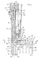
- Figure 4 is a schematic partially cross-sectional view of the driver attachment of Figure 1 in a fully extended position as seen in Figure 1 through a plane passing through the longitudinal axis of the drive shaft and centrally of the screws in the screwstrip;
- Figure 5 is a view identical to Figure 4 but with the driver attachment in a partially retracted position in driving a screw into a workpiece;
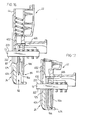
- Figure 6 is a rear exploded pictorial view of the slide body shown in Figure 3 showing its nose portion and rear portion separately;
- Figure 7 is a front exploded view of the two components of the slide body as seen in Figure 6 ;
- Figure 8 is a front view of the slide body as seen in Figure 7 but with the nose portion and rear portion assembled in a forward position;
- Figures 9A and 9B are schematic cross-sectional end views along section lines 9A-9A' and 9B-9B' in Figure 8 ;
- Figure 10 is a front pictorial view of the slide body of Figure 7 with the nose portion in a partially retracted toward a rearward position;
- Figure 11 is a front view of the slide body similar to that as seen in Figure 8 but with the nose portion in rearward position;
- Figure 12 is a front cross-sectional view along line 12-12' in Figure 9 of the slide body of Figure 8 with the nose portion in a forward position with a screwstrip having (31 ⁇ 2 inch) 8,89 cm screws;
- Figure 13 is a front cross-sectional view of the slide body, the same as in Figure 12 but with the nose portion in a rearward position;
- Figure 14 is a front cross-sectional view of the slide body as in Figure 12 but with the nose portion retracted to engage the next screw and without the rear body being retracted relative the housing;
- Figure 15 is a front cross-sectional view as in Figure 14 but with both the portion and body retracted relative the housing;
- Figure 16 is a front cross-sectional view of the slide body in a position as in Figure 14 but with (21 ⁇ 2 inch) 6,35 cm screws;
- Figure 17 is a front cross-sectional view similar to that in Figure 16 with the nose portion in a rearward position as in Figure 11 ;
- Figure 18 is a front cross-sectional view of the slide body in a position as in Figure 14 but with 3,81 cm (11 ⁇ 2 inch) screws;
- Figure 19 is a front cross-sectional view similar to that in Figure 18 , however, with the nose portion in a rearward position as in Figure 11 ;
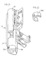
- Figure 20 is a pictorial view of a second embodiment of a slide body with a replaceable, invertible nose collar having protrusions extending forwardly;
- Figure 21 is a pictorial view of the slide body of Figure 20 with the nose collar replaced inverted to present a forward surface without protrusions;
- Figure 22 is a pictorial view of the nose collar from Figure 20 ;
- Figure 23 is a schematic cross-sectional view along line 23-23' in Figure 4 merely showing the screwstrip and shuttle in a fully advanced position;
- Figures 24 and 25 are views the same as Figure 23 but with the shuttle being withdrawn in an intermediate position in Figure 24 and in a fully withdrawn position in Figure 25 ;
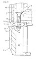
- Figure 26 is a perspective view of a screwstrip having locating notches or slots
- Figure 27 is a view similar to that of Figure 4 showing the slide body of Figures 1 to 19 modified for use with the notched screw strip of Figure 26 .
- FIG. 1 which shows a complete power screwdriver assembly 10 in accordance with the present invention.
- the assembly 10 comprises the power driver 11 to which a driver attachment 12 is secured.
- the driver attachment 12 receives a collated screwstrip 14 comprising a plastic strap 13 and spaced screws 16 held by the strap 13 to be successively driven.
- the major components of the driver attachment 12 comprise a housing 18 and a slide body 20.
- the housing 18 is adapted to be secured to a driver housing 30 (only shown in Figure 4 ) of a power driver 11 with a chuck 32 of the power driver engaging a driver shaft 34 for rotation of the driver shaft about an axis 52.
- the slide body 20 is received within the housing 18 for relative sliding parallel the axis 52.
- the slide body 20 has a nose portion 24 and a rear portion 22 as best seen in Figure 6 .
- the nose portion 24 has a guideway 82 extending axially therethrough coaxially about the driver shaft 34.
- the rear portion 22 carries a screw feed channel element 76 providing a channelway 88 which extends radially relative the longitudinal axis 52 to intersect with the guideway 82 and provide a mechanism for screws 16 held in a plastic strap 13 to be successively fed into the guideway 82 into axial alignment with the driver shaft for driving forwardly from the guideway 82 by the bit 122 carried on the forward end of the driver shaft 34.
- An exitway or exit opening 87 is provided in the slide body 20 to permit spent plastic strap 13 from which screws 16 have been driven to exit from the guideway 82.
- the exit opening 87 is defined between the nose portion 24 and the rear portion 22.
- An advance mechanism is provided to successively advance screws into the guideway 82 with each subsequent cycle of retraction of the slide body 20 into the housing 18 so as to drive a screw, and extension of the slide body 20 out of the housing 18 to withdraw the driver shaft 34 rearwardly and advance a new screw into the guideway 82.
- FIG. 3 showing an exploded view of major components of the driver attachment 12, namely housing 18 and a slide body 20 comprising a rear portion 22 and a nose portion 24.
- Figures 4 and 5 show in cross-section the interaction of these components.
- the rearmost end 26 of the housing 18 has a rearwardly directed socket 27 with a longitudinal slot 28 in its side wall to receive and securely clamp the housing 18 onto the driver housing 30 of the power driver 11 so as to secure the housing 18 of the driver attachment to the housing 30 of the power driver against relative movement.
- the power driver 11 has a chuck 32 rotatable in the driver housing 30 by an electric motor (not shown). The chuck 32 releasably engages the driver shaft 34 in known manner.
- the slide body 20 is slidably received in the housing 18 with the driver shaft 34 received in a bore passing through the slide body 20.
- the spring 38 is disposed between the housing 18 and the slide body 20.
- a first slide stop 23, shown in Figure 3 is secured to the rear portion 22 of the slide body.
- a second slide stop 25 is secured to the nose portion 24.
- Two slide stops 23 and 25 each slide in two longitudinal slots 40 and 41, one on each side of the side walls 42 and 43 of the housing 18 to key each of the nose portion and rear portion to the housing 18 against relative rotation and to independently prevent the nose portion or rear portion being moved forwardly out of the housing 18.
- the slide body 20 comprises two principal components, namely, the nose portion 24 and the rear portion 22 which are best seen in an exploded pictorial rear view in Figure 6 and in an exploded front view in Figure 5 .
- the rear portion in effect, comprises a part-cylindrical tubular element 44 from which, on one side, there extends a flange element 46 and a radially extending screw feed channel element 76.
- the flange 46 is adapted to carry a mechanism which interacts with the housing such that with relative sliding of the rear portion 22 relative the housing, a screwstrip in the screw feed channel element 76 will be advanced.
- the tubular element 44 is open along one side through a longitudinal open slotway 106 extending circumferentially through an angle of about 90° relative the axis 52.
- the rear portion 22 carries on the outer surface of its tubular element 44 a longitudinally extending rib 448 which is square in cross-section and is adapted to be received within the slot 40 in the side wall 42 of the housing to guide the rear portion 22 in longitudinal sliding within the housing.
- Two holes 450 are shown for attachment of the slide stop 23 to the rear portion 22 on the outside of the housing.
- the flange 46 of the rear portion 22 carries a longitudinally extending rib 452 of generally square shape which is adapted to be received within a complementary longitudinal slotway in the inside of the rear wall 42 of the housing.
- This longitudinal rib 452 on the flange 46 is best seen in Figure 6 .
- the nose portion 24 of the housing 20 has a generally part-cylindrical screw guide tube 75 arranged generally coaxially about longitudinal axis 52.
- the guide tube 75 defines cylindrical bore or guideway 82 extending axially through the guide tube with the guideway 82 delineated and bordered, at least in part, by part-cylindrical inner surfaces of the guide tube 75.
- Guide tube 75 has a screw access opening 86 opening on one side effectively throughout the length of the guide tube and a strap exitway 87 opening out of the interior of the guide tube 75 on the other side. Rearward of the exitway 87, there is a rear section 402 of the guide tube 75 and forward of the exitway 87, there is a forward section 404 of the guide tube 75.
- a front pillar 406 on the front of the nose portion 24 joins the forward section 404 of the guide tube 75 to the rear section 402 of the guide tube.
- a rear pillar 408 on the rear side of the nose portion joins the front section 404 with the rear section 402. The rear pillar 408 extends rearwardly to a rear end 117 to engage a depth setting cam member 114 as will be described later.
- the rear pillar 408 carries along its length disposed parallel the axis 52 a longitudinal rib 410 of square shape in cross-section which is adapted to be received in a complementary longitudinal slot 40 in the side wall 43 of the housing to assist in guiding the nose portion in longitudinal sliding in the housing.
- the rear pillar 408 carries near its end two threaded openings 412 via which the slide stop 25 is secured to the nose portion 24.
- the front pillar 406 also carries a longitudinally extending rib 414 of square cross-section which is adapted to be received within the slot 41 in the front side wall 42 of the housing to assist in guiding the nose portion in longitudinal sliding within the housing.
- the rear section 402 of the guide tube 75 has a part cylindrical inner surface 416 of a diameter marginally greater than the diameter of a screw to be received therein so as to assist in coaxially locating a screw coaxially with the axis 52.
- the rear section 402 of the guide tube 75 has a part cylindrical outer surface 418 which is sized to be marginally smaller than a cylindrical inner surface 420 of the tubular element 44 of the rear portion such that the rear section 402 of the guide tube 75 is axially slidably received within the tubular element 44 of the rear portion.
- the rear pillar 408 When assembled, the rear pillar 408 is slidably received in the open slotway 106 of the tubular element 44 to close the slotway 106 with the rear section 402 of the guide tube 75 received coaxially within the tubular element 44 longitudinally slidably therein.
- the tubular element 44 has a blind slot 422 through its wall open forwardly and closed at a rear end 424.
- the front pillar 406 is axially slidable into this blind slot 422.
- the front pillar 406 carries a stop shoulder 426 which engages the blind end 424 of the slot 422 to limited rearward movement of the nose portion 24 relative the rear portion 22 at the rearward position. Receipt of the front pillar 406 in the blind slot 422 also assists in securing the nose portion 24 to the rear portion 22 against relative rotation about axis 52.
- the edges of the part-cylindrical tubular element 44 adjacent its longitudinal open slotway 106 are provided with outwardly extending ribs 428 to be engaged in a complementary channelway 430 formed in the edge of the rear pillar 408 as best seen in Figure 9B .
- tubular element 44 Adjacent the blind slot 422, the tubular element 44 extends forwardly on the side opposite the screw feed channel element 76 so as to present a forwardly directed rear strap locating surface 432.
- the forward section 404 of the guide tube 75 has an inner surface which is cylindrical about the axis 52 and of the same radius as the inner surface 416 of the rear section 402 of the guide tube, that is, sized to be marginally greater than the head of the screw to be received therein.
- the guideway 82 within which a screw to be driven is to be located coaxially about the axis 52.
- the guideway 82 extends forwardly through the nose portion 24 and opens forwardly from the nose portion 24 as forward opening fastener exit opening 136 through which a screw is to be driven.
- Screw access opening 86 is provided to permit the screwstrip 14 including retaining strap 13 and screws 16 to move radially inwardly into the guideway 82 from the right as seen in Figure 4 and 5 .
- Each screw preferably has a head 17 with a diameter marginally smaller than the diameter of the guideway 82. It follows that where the head of the screw is to enter the guideway 82 over the rear section of the guide tube 402, the screw access opening must have a circumferential extent of at least about 180°. Where the shank of the screw is to enter the guideway as over the forward section 404 of the guide tube 75, the screw access opening may have a lesser circumferential extent.
- inner surface 416 engages the radially outermost periphery of the head 17 of the screw 16, to axially locate the screw head 17 coaxially within the guideway 82 in axial alignment with the drive shaft 34.
- inner surface 416 preferably extends about the screw sufficiently to coaxially locate the screw head and, thus, preferably extends about the screw head at least 120°, more preferably, at least 150° and, most preferably, about 180° or slightly greater than 180°.
- An exitway 87 shown towards the left-hand side of the guide tube 75 in Figures 4 and 5 , is provided of a size to permit the spent plastic strap 13 from which the screws 16 have been driven to exit from the guideway 82.
- the inner surface of the forward section 404 of the guide tube 75 is shown as extending greater than 180° about the longitudinal axis 52 so as to continue to positively coaxially guiding the head 17 of a screw 16 being driven.
- a forwardmost contact surface 130 is disposed about the fastener exit opening 136 adapted to engage the outer surface 132 of a workpiece 134.
- the fastener exit opening 136 is provided on a touch down flange 434 on the nose portion 24 which flange 434 extends transversely to the axis 52 adjacent to the exit opening 136.
- the flange 434 has a rearwardly directed surface 436 which carries a conical recess 438 which is adapted to engage the tip of a next screw to be driven and in certain circumstances to sandwich the next screw axially between the flange 434 and the screw feed channel member 76 of the rear portion 22 and thus prevent further rearward movement of the nose portion 24 relative the rear portion 22.
- the forward section 404 of the guide tube 75 Adjacent the rear pillar 408, the forward section 404 of the guide tube 75 carries a rear stop shoulder 440 which is adapted to engage a forwardly directed surface 442 of the wall 91 on the screw feed channel element 76 to stop rearward movement of the nose portion relative the rear portion in the rear position.
- the rear portion 22 and nose portion 24 are coupled together for displacement parallel to the axis 52 of the drive shaft between a forward position and a rearward position.
- the forward position is illustrated in Figure 8 and represents a position in which the nose portion 24 is moved forwardly to a maximum extent relative to the rear portion 22.
- the rearward position is illustrated in Figure 11 and illustrates a position in which the nose portion is moved rearwardly to a maximum extent relative to the rear portion.
- Figure 10 is a pictorial view illustrating the rear portion and nose portion as coupled together for relative longitudinal sliding and showing a position intermediate the forward portion and the rearward portion.
- Figure 12 illustrates a cross-sectional view through Figure 8 showing the forward position.
- Figure 13 illustrates a cross-section view through Figure 11 showing the rearward.
- the exitway 87 has a rearwardly directed front strap locating surface 125 carried by the nose portion 24 and, as well, a forward side surface 444 and rear side surface 446 defined by the inside surfaces of the front pillar 406 and rear pillar 408.
- a rear perimeter of the exitway 87 is defined by the forwardly directed rear strap support surface 432 of the tubular element 44 of the rear portion 22.
- the slide body comprising the rear portion 22 and the forward portion 24 are coupled together and are slidably received within the housing 18.
- a compression spring 38 is disposed between the housing 18 and the slide body 20 coaxially about the driver shaft 34.
- the socket 27 of the housing 18 ends at its forward end as a plate 456 with a central opening therethrough, through which the drive shaft extends.
- An elongated tube 458 is formed as an integral part of this plate extending forwardly from the plate.
- a rear end of the spring 38 engages the forward surface of the plate 456 with the tube extending coaxially within the spring 38 to assist in preventing the spring from engaging the driver shaft.
- the front end of the spring 38 is received within the tubular element 44.
- the spring 38 is of a diameter smaller than the inside diameter of the inner surface 420 of the tubular element 44. As best seen in Figures 12 and 13 , the forward end of the spring, at all times, engages a rearwardly directed surface 460 on the rear section 402 of the guide tube 75 so as to bias the nose portion 24 forwardly relative to the housing 18.
- the rear portion 22 carries at a forward location in the tubular element 44 a rearwardly directed spring stop shoulder 462 which extends radially inwardly further than the inner surface 420 of the tubular element 44 over a small angular sector of the tubular element 44.
- the tubular element 44 has a wall 464 which extends about 270° about the axis and defines inner surface 420 inwardly thereof.
- the spring stop shoulder 462 comprises part of the tubular element 44 and is fixed to the wall 464 extending radially inwardly thereof.
- the guide tube 75 as seen in Figure 9B , includes the rear pillar 408 and the rear section 402 carrying the surface 460 to be engaged by the spring.
- the rear section 402 has its outer surface 418 for sliding inside the inner surface 420 of the tubular element 44.
- the rear section 402 extends about 240° about the axis 52 and the spring stop shoulder 462 is a rear end of a part-cylindrical tube complementary to the rear section 402 but fixed to the tubular element 44.
- This spring stop shoulder 462 is adapted to be engaged by the forward end of the spring 38 so as to urge the rear portion 22 to a forward extended position relative to the housing 18.
- the front end of the spring 38 has biased the nose portion forwardly to the forward portion relative to the rear portion and, in this position, the spring 38 engages both the spring stop shoulder 462 on the rear portion and the rear surface 460 on the nose portion such that the spring 38 acts to bias the entire slide body forwardly.
- the screw strip is illustrated as having screws of a 8,89 cm (31 ⁇ 2 inch) length which are held in a plastic strap 13 as are commercially available with the strap 13 having a forward surface 222 at a distance D1 from the tops of heads of the screw and a rear surface 223 at a distance D2 from the tops of the heads of the screw.
- screwstrips carrying screws of 8,89 cm (31 ⁇ 2 inch) length are sold under the trade mark QUIK DRIVE , have the forward surface 222 located at a distance D1 equal to 3,175 cm (11 ⁇ 4 inches) from the head of the screw, the strap having a height measured axially the screws of about 0,79375 cm (5/16 of an inch) and the rear surface 223 of the strap located a distance of D2 of about 0,79375 cm (15/16 inch) from the top of the head of a screw.
- Figure 12 shows the nose portion 24 in a forward position relative the rear portion 22.
- the nose portion and rear portion are configured as adapted to drive screws of a maximum length of about 8,89 cm (31 ⁇ 2 inches) as are shown in Figure 12 .
- the axially distance between the forwardly directed surface 466 of the wall 93 of the screw feed channel element 76 and the rearwardly directed surface 436 of the flange 434 on the nose portion 24 is greater than the length of the screws. This permits the screws to be advanced in known manner radially relative the axis 52 into the guide way 82 to be disposed coaxially with the driver shaft.
- Figure 14 illustrates a position in which a screw to be driven, indicated as 16a, is coaxially disposed within the guide way 82 with spent strap 13 from which screws have been driven extending out the exitway.
- the nose portion has been engaged with the work piece and the nose portion has been moved rearwardly relative to the rear portion to an extent that the tip of the next screw to be driven, indicated 16b, is engaged in the recess 438 in the flange 434.
- FIG. 14 illustrates a condition in which the slide body 20 comprising the nose portion 24 and rear portion 22 fixed in the condition shown is slid rearwardly relative the housing 18 and the bit has just engaged the screw 16a to be driven.
- Figure 15 illustrates a subsequent condition that the driver of Figure 14 comes to assume after the slide body 20 has retracted further into the housing 18 towards the retracted position.
- the driver shaft and its bit have engaged the screw 16a to be driven and have driven it forwardly into the workpiece severing the screw 16a from engagement with the strap 13.
- the relative position of the screws and strap 13 other than the screw 16a being driven and the relative position of the nose portion 24 relative to the rear portion 22 has not changed, however, the spring 38 is shown to have been increasingly compressed as would be the case since the entire slide body 20 has been moved rearwardly relative to the housing 18, not shown.
- Figures 16 and 17 illustrate the identical nose portion and rear portion to that shown in Figures 12 and 14 .
- Figures 16 and 17 illustrate driving a screwstrip with screws of 21 ⁇ 2 inch length.
- the 21 ⁇ 2 inch screws as illustrated in Figures 16 and 17 are commercially available screws sold under the trade mark QUIK DRIVE and in which the distance D1 of the forward surface 222 from the top of the head is 0,79375 cm (5/16 inch), the height of the strap 13 as measured parallel the axis of the screws is 0,79375 cm (5/16 inch) and the distance D2 of the rear surface 223 is from the top of the screws is 1,42875 cm (9/16 inch).
- Commercially available screws sold under the trade mark QUIK DRIVE which are of lengths between 7,62 cm and 3,175 cm (3 inches and 11 ⁇ 4 inches) have a similar configuration with D1 being 0,79375 cm (5/16 inch), the height of the strap being 0,79375 cm (5/16 inch) and D2 being 1,42875 cm (9/16 inch).
- the screws illustrated in all the Figures, including Figures 12 and 14 to 19 all have the same head diameter, being a head diameter complementary to that of the diameter of the guideway 82.
- Figure 16 illustrates a condition in which, with the nose portion 24 in the forward position, the screwstrip has been advanced with a screw 16a to be driven coaxially in the guideway 82 and the next screw 16b adjacent to it.
- Figure 17 illustrates a condition in which, on urging the tool into a workpiece, the nose portion has moved rearwardly towards the rear position relative to the rear portion 22 such that two conditions arise. Firstly, the next screw 16b has been sandwiched between the flange 434 of the nose portion and the screw feed channel element 76 of the rear portion.
- FIG. 17 illustrates a condition in which the nose portion 24 and rear portion 22 are approximately in the rear position.
- Figures 18 and 19 show the use of the identical nose portion and rear portion to that shown in Figures 16 and 17 but in conjunction with a screwstrip having screws of a length of 3,81 cm (11 ⁇ 2 inches) and relative distances D1 and D2 the same as that with a 6,35 cm (21 ⁇ 2 inch) screw illustrated in Figures 16 and 17 .
- Figure 18 illustrates the nose portion 24 and rear portion 22 in the forward position.
- Figure 19 illustrates the nose portion 24 and rear portion 22 in a position which is substantially the rear position and in which the spent strap 13 is engaged, with the forward surface 222 of the strap 13 engaged by the rearwardly directed forward locating surface 125 of the nose portion and the rear surface 223 of the strap 13 engaged by the forwardly directed rear locating surface 432 of the rear portion.
- the nose portion and rear portion illustrated have been particularly adapted such that when screws of 6,35 cm (21 ⁇ 2 inch) length are shown as illustrated in Figures 16 and 17 , such screws are held both by the next screw 16b being sandwiched between the touchdown flange 434 on the nose portion and the rear portion and, as well, with the spent strap 13 being engaged by the forward strap support surface 125 of the nose and the rear locating surface 432 of the rear portion.
- the slide body as illustrated in Figures 12 to 19 is adapted for driving screws of substantially different lengths, for example, from 8,89 cm (31 ⁇ 2 inch) lengths to 3,81 cm (11 ⁇ 2 inch) lengths and shorter without the need for any adjustment or modification of the driving tool.
- that screwstrip may be withdrawn from the tool and another screwstrip having screws of, say, 3,81 cm (11 ⁇ 2 inch), may then be inserted into the tool and directed driven by the tool without the need for any adjustment of the tool whatsoever other than replacement of one screwstrip by another screwstrip.
- the spent strap 13 is shown as being engaged both on its forward surface 222 by the forward locating surface 125 and on its rear surface 223 by the rear locating surface 432.
- the tool will function merely by engagement of the forward surface 222 of the strap 13 by the front locating surface 125 without need for the rear surface 223 to be engaged by the rear locating surface 432 of the rear portion. It is preferred, however, if both the forward surface 222 and the rear surface 223 are engaged. Most preferably, it is advantageous that the spent strap 13 is pinched between the forward locating surface 125 and the rear locating surface 432.
- the strap 13 is preferably pinched and, to some extent, compressed between the forward locating surface 125 and the rear locating surface 432 when the nose portion 22 is proximate the rearward position relative to the rear portion.
- the extent of axial compression may be limited by the nose portion assuming the rearward portion relative to the rear portion.
- the rear surface 223 of the strap 13 should advantageously be located a constant distance forward from the heads of the screw, preferably, the top surface of the screw.
- the strap 13 has a constant height as measured parallel to the axis of the screws such that both the rearward surface 223 and the forward surface 222 are located at constant fixed distances of the head of the screw.
- the present invention provides in combination an autofeed screwdriver attachment for collated screws as described together with collated screws having at least with one of the forward surface 222 and the rear surface 223 at a constant distance from the head of the screw and preferably both at constant distances.
- the rear surface 223 of the strap is engaged by the forward locating surface 432.
- the entire rear surface 223 of the strap 13 be located at a constant distance from the heads, it is possible to merely have the portions of the strap between the screws which is to be engaged by the rear locating surface 432 to be at a constant distance from the heads.
- the entirety of the forward surface 222 may be a constant distance from the heads or merely the portion to be engaged by the forward locating surface 125.
- the nose portion and rear portion screws of a length less than 21 ⁇ 2 inches are driven without the flange 434 functioning to hold the screws to be driven.
- the present invention includes embodiments in which the nose portion is provided without the flange 434 and no provision is made to hold the screwstrip by sandwiching the next screw between the nose portion and the rear portion. With the flange 434 removed, a screwstrip could be held in a similar manner as that described above in Figures 18 and 19 without the next screw being sandwiched and with the strap 13 pinched by or engaged between both the rear locating surface 432.
- a split slide body of this application including its separate nose portion and rear portion may be adapted for use in many other types of fastener driving tools in which the screws or screwstrips are advanced by different mechanisms and different mechanisms are provided juxtaposition between the slide body and housing to activate the advance of the screwstrip.
- the preferred embodiments utilize a single spring 38 to both bias the slide body 20 forwardly and to bias the nose portion 24 forwardly relative to the rear portion.
- two springs could be provided, one operative to act between the housing 18 and the rear portion 22 and the second operative to act between the rear portion 22 and the front portion 24.
- the spring to act between the nose portion and the rear portion would compress under less forces than that required to compress the spring between the rear portion 22 and the housing 18 such that the nose portion 25 would retract relative the rear portion before the rear portion retracted relative to the housing.
- the screw feed channel element 76 carried on the rear element 22 is best seen in Figures 2 , 3 and 4 as providing a channelway 88 which extends radially relative the longitudinal axis 52 to intersect with the guideway 82 in the guide tube 75.
- the channelway 88 opens to the guideway 82 through the screw access opening 86.
- the channelway 88 provides a channel of a cross-section similar to that of the screw access opening 86 from the screw access opening 86 to a remote entranceway opening 90.
- the channelway 88 is defined between two side walls 91 and 92 joined by a top wall 93.
- the major side wall 91 is shown as extending from the heads 17 of the screws 16 forwardly to at least partially behind the plastic retaining strap 13.
- the lesser side wall 92 is shown as extending from the heads 17 of the screws 16 forwardly to above the plastic strap 13. As seen in Figures 18 and 19 , the forward surface 454 of the lesser side wall 92 is immediately above the rear surface 223 of the strap 13 and assists in locating the strap. In the preferred embodiment, the rear strap locating surface 432 is disposed at the same axial location as the forward surface 454 of the lesser side wall 92. Stopping the lesser side wall from extending down over the strap 13 assists in reducing friction between the strap 13 and the lesser side wall.
- the side walls 91 and 92 define the channelway 88 with a cross-section conforming closely to that of the screwstrip 14 and its strap 13 and screws 16 with an enlarged width where the heads of the screws are located and an enlarged width where the retaining strap 13 is provided about the screws.
- the side walls 91 and 92 also have an enlarged funnelling section at the entranceway opening 90 which tapers inwardly to assist in guiding the screwstrip to enter the channelway.
- a lever 48 is pivotally mounted to the flange element 46 of the rear portion 22 by axle 50 for pivoting about an axis of axle 50 normal to the longitudinal axis 52 which passes centrally through the drive shaft 34 and about which the drive shaft is rotatable.
- Lever 48 has a forward arm 54 extending forwardly to its front end 56 and a rear arm 58 extending rearwardly to its rear end 60.
- the rear arm 58 of the lever 48 carries a cam pin 502 near its rear end 60.
- the cam pin 502 is a removable cylindrical pin threadably received in threaded opening 503 in rear arm 58.
- a cam slot 506 is provided in the side wall 302 of the housing 18.
- the cam slot 506 has a first camming surface 508 and a second camming surface 510 spaced therefrom and presenting different profiles as best seen in side view in Figure 3 .
- the cam pin 502 is received in cam slot 506 between the first and second camming surfaces 508 and 510 for engagement of each under different conditions of operation.
- Spring 69 about axle 50 biases the lever 48 in a clockwise direction as seen in Figure 5 and thus biases the lever to pivot in a direction which moves a shuttle 96 shown in Figure 2 towards the axis 52 of the guide tube and biases the cam pin 502 towards the first camming surface 508.
- the slide body 20 moves relative the housing 18 in a cycle of operation in which the rear portion 22 of the slide body moves relative the housing in a retracting stroke from the extended position to the retracted position and then moves in an extending stroke from the retracted position to the extended position.
- the cam pin 502 will engage either the first camming surface 508 or the second camming surface 510 will depend on a number of factors. Most significant of these factors involve the resistance to movement of the shuttle 96 in either direction as compared to the strength of the spring 69 tending to move the shuttle 96 towards axis 52.
- the bias of the spring 69 Under conditions in which the bias of the spring 69 is dominant over resistance to movement of the shuttle 96, then the bias of the spring will place the cam pin 502 into engagement with the first camming surface 508 with relative motion of the lever 48 and therefore the shuttle 96 relative the position of the slide body 20 in the housing 18 to be dictated by the profile of the first camming surface 508. Under conditions where the resistance to movement of the shuttle is greater than the force of the spring 96, then the cam pin 502 will either engage the first camming surface 508 or the second camming surface 510 depending on the direction of such resistance and whether the slide body is in the retracting stroke or the extending stroke.
- the first camming surface 508 has a first portion 514, a second portion 516 and a third portion 518.
- the first portion 514 and the second portion 518 are substantially parallel the driver shaft axis 52.
- Second portion 516 extends at an angle rearwardly and towards axis 52.
- the second camming surface 510 has a first portion 520 which extends angling forwardly and away from axis 52 and a second portion 522 which is substantially parallel the axis 52.
- the third portion 518 of the first camming surface 508 and the second portion 522 of the second camming surface 510 are parallel and disposed a distance apart only marginally greater than the diameter of cam pin 502 so as to locate the cam pin 506 therein in substantially the same position whether the cam pin 502 rides on first camming surface 508 or second camming surface 510.
- the cam slot 506 has a front end 512 where the first portion 514 of the first camming surface 508 merges with the first portion 520 of the second camming surface 510.
- the width of the cam slot 506 is also only marginally greater than the diameter of the cam pin 502 so as to locate the cam pin 506 therein in substantially the same position whether the cam pin 502 rides on the first camming surface 508 or the second camming surface 510.
- the first portion 520 of the second camming surface 510 is spaced from the first camming surface 508 and, in particular, its first portion 514 and second portion 516 by a distance substantially greater than the diameter of cam pin 502.
- the major side wall 91 is provided on its exterior back surface with a raceway 94 extending parallel the channelway 88 and in which a shuttle 96 is captured to be slidable towards and away from the guide tube 75 between an advanced position near the guide tube and a withdrawn position remote from the guide tube.
- the shuttle 96 has a rear surface in which there is provided a rearwardly directed opening 98 adapted to receive the front end 56 of the forward arm 54 of lever 48 so as to couple the shuttle 96 to the lever 48 for movement therewith.
- Shuttle 96 carries a pawl 99 to engage the screwstrip 14 and with movement of the shuttle 96 to successively advance the strip one screw at a time.
- the shuttle 96 has a fixed post 100 on which the pawl 99 is journalled about an axis parallel the longitudinal axis 52 about which the driver shaft rotates.
- the pawl 99 has a first pusher arm 101 at its forward end to engage a first lead screw 16a and a second pusher arm 601 to engage a second screw 16b.
- the pusher arms extend out from slot 103 in the shuttle 96 and through a slot 105 in the major side wall 91 of the feed channel element 76 to engage and advance the screwstrip.
- the pawl 99 has a manual release arm 102 which extends out away from the screwstrip through the opening 104 from slot 103 of the shuttle 99.
- a torsional spring 615 shown only in Figure 25 , is disposed about post 100 between pawl 99 and shuttle 96 and urges the first pusher arm 101 counterclockwise as seen in Figure 23 .
- the torsional spring biases the pusher arms into the screwstrip 14.
- the engagement of release arm 102 on the left-hand end of opening 104 limits the pivoting of the pawl 99 counterclockwise to the blocking position shown in Figure 9 .
- the first pusher arm 101 has a cam face 107 and the second pusher arm 601 has a cam face 607.
- the cam faces 107 and/or 607 will engage the screws 16b and 16c, respectively, and/or the strap 13 and permit the pawl 99 to pivot about post 100 against the bias of the torsional spring to a passage position so that the shuttle 96 may move to the right relative the screwstrip 14.
- the first pusher arm 101 has an engagement face 108 to engage the screws 16 and the second pusher arm 601 has an engagement face 608 to also engage the screws 16.
- the engagement faces 108 and 608 will engage the screw 16b and 16c, respectively, and/or strap 13 and advance the screwstrip to the right as seen in Figure 25 so as to position a screw 16b into the guideway 82 in a position to be driven and to hold the screwstrip 14 against movement towards the left.
- the engagement face 108 of the first pusher arm 101 engages the screw 16 between its head 17 and the strap 13 as this has been found advantageous, particularly to avoid misfeeding with a nose portion 24 as shown with engagement of the screw heads in the channelway 88 and engagement of the spent strap 13 with the support surface 125.
- a dashed line 611 represents a plane of advance in which the axis of each of the screws 16 lie and along which the screwstrip 14 is advanced towards the left such that screws may successively be brought into alignment with the driver shaft whose axis 52 is to occur at the intersection of advance plane 611 with a dashed axis line 612.
- spent strap 13 is shown with a broken sleeve 220a from which a screw has been driven.
- Figure 25 shows the shuttle 96 withdrawn rearwardly sufficiently to a position that the engagement faces 108 and 608 are to the right, rearward of the screws 16b and 16c in sleeves 220b and 220c and with the screw 16a, not seen, as it has been driven from the fractured sleeve 220a.
- the shuttle 96 is moved to the left relative the axis 52 thereby advancing the screwstrip 14, moving it to the left and placing the screw 16b in the sleeve 220b into axial alignment with the driver shaft axis 52.
- both the first and second pusher arms 101 and 601 engage their respective screws and urge the screwstrip 14 to advance.
- the release arm 102 permits manual withdrawal of the screwstrip 14.
- a user may with his finger or thumb manually pivot the release arm 102 against the bias of spring so that both the first pusher arm 101 and its engagement face 108 and the second pusher arm 601 and its engagement face 608 are moved away from and clear of the screwstrip 14 whereby the screwstrip may manually be withdrawn as may be useful to clear jams or change screwstrips.
- a fixed post 432 is provided on shuttle 96 opposed to the manual release arm 102 to permit pivoting of the release arm 102 by drawing the release arm 102 towards the fixed post 432 as by pinching them between a user's thumb and index finger.
- the lever 48 couples to the shuttle 96 with the forward arm 54 of lever 48 received in the opening 98 of the shuttle 96.
- Sliding of the slide body 20 and the housing 18 in a cycle from an extended position to a retracted position and then back to an extended position results in reciprocal pivoting of the lever 48 about axle 50 which slides the shuttle 96 between the advanced and withdrawn position in its raceway 94 and, hence, results in the pawl 99 first retracting from engagement with a first screw to be driven to behind the next screw 16 and then advancing this next screw into a position to be driven.
- the nose portion 24 carries the guide tube 75 with its screw locating guideway 82.
- the rear portion 22 carries the screw feed channel element 76 with its channelway 88, and screw feed advance mechanism with the reciprocating shuttle 96 and pawl 99 to advance the screwstrip 14 via the channelway 88 into the guideway 82.
- Each of the guideway 82, channelway 88 and shuttle 96 are preferably customized for screwstrips and screws or other fasteners of a corresponding size other than length.
- size includes shape, head diameter, shaft diameter, retaining strip configuration, spacing of screws along the retaining strip and the presence or absence of washes amongst other things.
- size does not, preferably, include a limitation to merely a single length since the preferred embodiments may drive screws having lengths from, for example, 31 ⁇ 2 inches to 11 ⁇ 2 inches without modifications.
- Different slide bodies are to be configured for different screwstrips and screws. Different modified slide bodies can be exchanged so as to permit the driver attachment to be readily adapted to drive different screwstrips and screws.
- the cross-sectional shape of the channelway 88 can be changed as can the diameter of the guideway 82.
- the length of the side walls 91 and 92 about the channelway 88 can be varied to accommodate different size screws which may require greater or lesser engagement.
- the construction of the housing 18 and slide body 20 provide for a compact driver attachment.
- the housing 18 includes side wall 301.
- the slide body 20 as best seen in Figure 3 has a part cylindrical portion of a uniform radius sized to be marginally smaller than a part cylindrical inner surface of the side wall 301 of the housing 18.
- the side wall 301 extends circumferentially about the part cylindrical portion of the slide body 20 to retain the slide body 20 therein.
- the housing has a flange portion 302 which extends radially from one side of the part cylindrical portion and is adapted to house the radially extending flange 46 of the rear portion 22 and the screw feed activation mechanism comprising the lever 48 and cam follower 62.
- the flange portion 302 is open at its front end and side to permit the screw feed channel element 76 to slide into and out of the housing 18.
- Concentrically located about the drive shaft 34 is the spring 38, the part cylindrical portions of the slide body 20, and the interior part cylindrical portions of the housing 18.
- the driver attachment is provided with an adjustable depth stop mechanism which can be used to adjust the fully retracted position, that is, the extent to which the slide body 20 may slide into the housing 18.
- the adjustable depth stop mechanism is best seen in Figures 3 and 5 .
- a depth setting cam member 114 is secured to the housing 18 for rotation about a pin 116, shown in Figure 5 , parallel the longitudinal axis 52.
- the cam member 114 has a cam surface 115 which varies in depth, parallel the longitudinal axis 52, circumferentially about the cam member 114.
- a portion of the cam surface 115 is always axially in line with the rear end 117 of the front portion 24.
- the extent the front portion 24 may slide into the housing 18 is determined by the depth of the cam member 114 axially in line with the rear end 117 of the nose portion 24 of slide body 20.
- the cam member 114 is preferably provided with a ratchet-like arrangement to have the cam member 114 remain at any selected position biased against movement from the selected position and with circular indents or depressions in the cam surface 115 to assist in positive engagement by the rear end 117 of the nose portion 24.
- a set screw 119 as seen in Figure 3 , is provided to lock the cam member 114 at a desired position and/or to increase resistance to rotation.
- the cam member 114 is accessible by a user yet is provided to be out the way and not interfere with use of the driver attachment.
- the depth stop mechanism controls the extent to which screws are driven into a workpiece and thus controls the extent of countersinking. Since the stop surface 117 is at a constant distance from the forwardmost surface 34 of the nose portion 24, and the bit 122 carried on the driver shaft 34 is in a constant position relative the housing, the depth stop mechanism will set the extent to which a screw is driven independent of the length of a screw and thus, when set, will drive or countersink the head of a screw of one length, say, 3 1 ⁇ 2 inches, the same amount as the head of a screw of, say, 2 inches. While a rotatable cam member 114 is shown various other cam members may be provided to present a surface to be engaged by the rear end 117 of the front portion, including stepped members which can slide to present different surfaces.
- the driver shaft 34 is shown in Figures 4 and 5 as carrying a split washer 120 engaged in an annular groove near its rear end 121 to assist in retaining the rear end of the driver shaft in the socket 27 of the housing 18.
- the driver shaft 34 is provided with a removable bit 122 at its forward end which bit can readily be removed for replacement by another bit as for different size screws.
- Such bits include sockets and the like and will preferably be of an outside diameter complementary to the inside diameter of the guideway 82.
- a screwstrip 14 containing a number of screws 16 collated in the plastic retaining strap 13 is inserted into the channelway 88 with the first screw to be driven received within the guideway 82.
- the power driver 11 is activated to rotate the driver shaft 34.
- the driver shaft 34 and its bit 122, while they are rotated, are reciprocally movable in the guideway 82 towards and away from the workpiece 134.
- manual pressure of the user pushes the housing 18 towards the workpiece 134.
- the forward end of the nose portion 24 engages the workpiece 134 to compress spring 38 so as to move the nose portion 24 relative the rear portion 22 from the forward position shown in Figure 4 to a rear position.
- the nose portion 24 is moved rearwardly until either a screw becomes sandwiched between the nose portion and the rear portion or the nose portion moves to the rear position relative the rear portion. Subsequently, the nose portion and rear portion move rearwardly from the extended position of the rear portion relative the housing to a retracted position relative the housing. On release of this manual pressure, in a return stroke, the compressed spring 38 moves the rear portion 22 back to its extended position relative the housing and the nose portion to its forward position relative the rear portion thereby moving the housing 18 and the driver shaft 34 away from the workpiece.
- the bit 122 engages the screw head 17 to rotate the first screw to be driven.
- the plastic strap 13 is formed to release the screw 16 as the screw 16 advances forwardly rotated by the driver shaft 34.
- the screw tip may engage in a workpiece before the head of the screw engages the strap such that engagement of the screw in the workpiece will assist in drawing the screw head through the strap to break the fragible straps, however, this is not necessary and a screw may merely, by pressure from the drive shaft, be released before the screw engages the workpiece.
- the plastic strap 13 deflects away from the screw 16 outwardly so as to not interfere with the screw 16 in its movement into the workplace.
- the driver shaft 34 axially moves away from the workpiece under the force of the spring 38 and a successive screw 16 is moved via the screw feed advance mechanism from the channelway 88 through the access opening 86 into the guideway 82 and into the axial alignment in the guideway with the driver shaft 34.
- the screw 16 to be driven is held in position in axial alignment with the driver shaft 34 with its screw head 17 abutting the side wall 83 in the guideway 82.
- a leading portion of the strap 13 from which screws have previously been driven extends outwardly from the guideway 82 through the exit opening 87 permitting substantially unhindered advance of the screwstrip 14.
- the rear locating surface 125 and forward locating surface 432 engage the forward and rear surfaces 222 and 223 of the strap 13.
- the screw may be axially located within the guide tube 75 by reason not only of the head of the screw engaging the side wall 83 of the guideway but also with the forward and rear surfaces 222 and 223 of the strap 13 being engaged in the locating surfaces 125 and 432 of the exitway 87.
- the driver attachment 12 disclosed may be provided for different applications.
- the driver may be used for high volume heavy load demands as, for example, as in building houses to apply sub-flooring and drywall.
- the power driver 11 comprising a typical screw gun which inherently incorporates a friction clutch and thus to the extent that a screw is fully driven into a workpiece, the clutch will, on the forces required to drive the screw becoming excessive, slip such that the bit will not be forced to rotate an engagement with the screw head and thus increase the life of the bit.
- the driver attachment may be constructed from different materials of construction having regard to characteristics of wear and the intended use of the attachment.
- a number of the parts may be moulded from nylon or other suitably strong lightweight materials.
- Parts which are subjected to excessive wear as by engagement with the head of the screw may be formed from metal or alternatively metal inserts may be provided within an injection moulded plastic or nylon parts.
- the optional provision of the nose portion 24 as a separate removable element has the advantage of permitting removable nose portions to be provided with surfaces which would bear the greatest loading and wear and which nose portions may be easily replaced when worn.
- the screw feed advance mechanism carried on the nose portion has been illustrated merely as comprising a reciprocally slidable shuttle carrying a pawl.
- Various other screw feed advance mechanisms may be provided such as those which may use rotary motion to incrementally advance the screws.
- the screws feed activation mechanism comprising the lever 48 and the cam follower have been shown as one preferred mechanism for activating the screw feed advance mechanism yet provide for simple uncoupling as between the shuttle 96 and the lever 48.
- Other screw feed activation means may be provided having different configurations of cam followers with or without levers or the like.
- the screwstrip 14 is illustrated as having screws extending normal to the longitudinal extension of the strap 13 and, in this context, the channelway 88 is disposed normal to the longitudinal axis 52. It is to be appreciated that screws and other fasteners may be collated on a screwstrip in parallel spaced relation, however, at an angle to the longitudinal axis of the retaining strip in which case the channelway 88 would be suitably angled relative the longitudinal axis so as to locate and dispose each successive screw parallel to the longitudinal axis 52 of the driver shaft.
- a preferred collated screwstrip 14 for use in accordance with the present invention is as illustrated in the drawings and particularly Figures 1 and 4 and are substantially in accordance with Canadian Patent 1,054,982 .
- the screwstrip 14 comprises a retaining strap 13 and a plurality of screws 16.
- the retaining strap 13 comprises an elongate thin band formed of a plurality of identical sleeves interconnected by lands 106.
- a screw 16 is received within each sleeve.
- Each screw 16 has a head 17, a shank 208 carrying external threads and a tip 15. As shown, the external threads extend from below the head 17 to the tip 15.
- Each screw is substantially symmetrical about a central longitudinal axis 212.
- the head 17 has in its top surface a recess for engagement by the screwdriver bit.
- Each screw is received with its threaded shank 208 engaged within a sleeve.
- the exterior surfaces of the sleeves come to be formed with complementary threaded portions which engage the external thread of the screw 16.
- Each sleeve has a reduced portion between the lands 106 on one first side of the strap 13. This reduced strength portion is shown where the strip extends about each screw merely as a thin strap-like portion or strap.
- the strap 13 holds the screws 16 in parallel spaced relation a uniform distance apart.
- the strap 13 has a forward surface 222 and a rear surface 223.
- the lands 106 extend both between adjacent screws 16, that is, horizontally as seen in Figure 4 , and axially of the screws 16, that is, in the direction of the longitudinal axes 212 of the screws.
- the lands comprise webs of plastic material provided over an area extending between sleeves holding the screws and between the forward surface 222 and the rear surface 223.
- a land 106 effectively is disposed about a plane which is parallel to a plane in which the axes 212 of all the screws lies.
- the lands 106 comprise a web which is disposed substantially vertically compared to the vertically oriented screws as shown in the figures.
- the lands 106 and the sleeves are disposed as continuous, vertically disposed strap 13 along the rear of the screws 16, that is, as a strap 13 which is substantially disposed about a plane which is parallel to a plane containing the axes of all screws.
- a preferred feature of the screwstrip 14 is that it may bend to assume a coil-like configuration due to flexibility of the lands 106, such that, for example, the screwstrip could be disposed with the heads of the screws disposed into a helical coil, that is, the plane in which all the axes 212 of the screws lie may assume a coiled, helical configuration to closely pack the screws for use. Having the lands 106 and sleeves as a vertically extending web lying in the plane parallel that in which the axes 212 permits such coiling.
- the invention is not limited to use of the collated screwstrips illustrated. Many other forms of screwstrips may be used such as the curved screwstrip illustrated in Figure 24 of U.S. Patent 5,927,163 to Habermehl and those illustrated in U.S. Patents 3,910,324 to Nasiatka ; 5,083,483 to Takaji ; 4,019,631 to Lejdegard et al and 4,018,254 to DeCaro .
- the guide tube 75 has an outboard side which is partially cut away on its outboard side and has a continuous portion 382 of its outer wall which separates the screw access opening 86 from the exit opening 87 on the outboard side of the guide tube 75.
- the outboard side is the side to which the strap 13 is deflected when a screw 16 is separated from the screwstrip 14.
- the passageway which extends from the screw access opening or entranceway 86 to the exit opening or exitway 87 is provided on its outboard side with a lateral strip receiving slotway 304 cut to extend to the outboard side from the cylindrical guideway 82.
- the slotway 304 as best seen in Figures 2 and 3 , is bounded on the outboard side by side surface 306, at its forward end by ramped surface 308 and forward surface 125, and at its rear end by rear surface 312.
- the access opening 86 forms an entranceway for the screwstrip 14 generally radially into the guideway 82 on one side.
- the exit opening 87 forms an exitway for portions of the strap 13 from which screws 16 have been driven, such portions being referred to as the spent strap 13.
- the exit opening or exitway 87 is shown as adapted to encircle the spent strap 13 with the exitway 87 bordered by rearwardly directed forward surface 125, forwardly directed rear surface 432, side surface 444 and side surface 446.
- ramped surface 308 is an axially rearwardly directed surface which angles forwardly from the forward surface 125 towards the entranceway.
- the ramped surface 308 extends forwardly from forward surface 125 with the ramped surface following the curvature of the side wall 83 as a ledge of constant width.
- the ramped surface 308 is useful to assist in driving the last screw from a strip as disclosed in U.S. Patent 5,934,162 to Habermehl .
- the fact that the exitway 86 encloses the spent strap 13 prevents the strap from rotating about the axis of the guideway to an orientation in which the screw 16 might be able to drop out of the guideway or the screw when driven is increasingly likely to jam.
- the spent strap 13 may extend from the exitway 87 at various angles limited only by the location of the side surfaces 314 and 316.
- Figure 3 is advantageous to better ensure that the last screw 16 in any screwstrip 14 is driven and to generally assist in reducing the likelihood of any screw 16 being driven becoming jammed in the guideway with the strap 13.
- Preferred strap segments for use with the drive attachment in accordance with this invention are, as shown in Figure 1 , segments of discrete length in which the axis of all straps lie in the same flat plane and in which the heads 17 of the screws are all located in a straight line.
- the forwardmost contact surface 130 on the nose portion 24 is shown as comprising a smooth, relatively flat central surface 140 and a part spherical smooth surface 141 thereabout carrying a plurality of protrusions 142.
- the part spherical surface 141 is effectively a portion of a sphere of a radius centered on a point on axis 52.
- the surface 141 extends radially to the side and rearwardly but not forwardly.
- a plurality of protrusions 142 are shown provided in an array on the surface 141.
- Each of the protrusions is shown as a spike-like member which extends at least partially forwardly from a base at the surface 141 to a distal end.
- the protrusions extend from the surface 141 parallel to axis 52 about the base.
- the protrusions may extend normal to the surface 140.
- Each of the distal ends of the protrusions are preferably adapted to provide for increased frictional engagement with a work surface as is advantageous to prevent slippage.
- the forward distal ends of the protrusions 142 preferably have a forward extent which is rearward of the forwardmost contact surface 130.
- the protrusions 142 preferably are located such that they do not engage a flat surface of a workpiece when the axis 52 is normal the flat surface of the workpiece but are adapted to engage a workpiece when the axis is tilted to the surface of the work surfaces.
- the surface 130 and protrusions 142 may be provided as described in USP 6,425,306 .
- FIG. 20 References made to Figures 20 , 21 and 22 will show a second embodiment of a slide body 20 in accordance with the present invention.
- the slide body of Figures 20 and 21 is effectively identical to that shown in the other Figures with the exception that the nose portion 24 has a removable C-shaped nose collar 500 which, in use, is fixably secured by a screw 502 about the front end of the nose portion 24.
- the C-shaped collar 500 is adapted to be removed and replaced by other C-shaped collars 500.
- the C-shaped collar shown in Figure 20 is provided on one end with protrusions similar to those described with reference to Figures 1 to 6 and provided on another end with a smooth surface without protrusions. Insofar as these protrusions may wear over time, then a new C-shaped collar 500 may be secured to the tool.
- the C-shaped collar as seen in Figure 22 , may be inverted from the position shown in Figure 20 to the position shown in Figure 21 such that a user may select whether to use a nose portion 24 with protrusions as seen in Figure 20 or a nose portion without protrusions as seen in Figure 21 .
- the C-shaped collar 500 capable of being inverted, it would be possible to merely provide two different C-shaped collars, one having protrusions and the other not having protrusions.
- the present invention has been described with reference to a nosepiece for an autofeed screwdriver. It is to be appreciated that a similar nose with a removable collar could be provided with tools of various types to drive fasteners including devices to drive a wide variety of different fasteners including screws and other threaded fasteners and nails, tacks, studs, posts and the like.
- FIGS. 26 and 27 show another embodiment of the present invention in which the screwstrip carries a locating system to facilitate location of the screwstrip relative the guide tube 76.
- a screwstrip is described in U.S.Patent 5,819,609 .
- Figure 26 shows screws 16 held in a plastic holding strap 13 substantially in accordance with Canadian Patent 1,054,982 .
- the strap comprises an elongate thin band formed of a plurality of identical sleeves 504 interconnected by lands 506.
- a screw 16 is received within each sleeve 504.
- Each screw 16 has a head 17, a shank 508 carrying external threads and a tip 15. As shown, the external threads extend from below the head 16 to the tip 116.
- Each screw is substantially symmetrical about a central longitudinal axis.
- the head 17 has in its top surface a recess for engagement by the screwdriver bit 122.
- Each screw is received with its threaded shank 508 engaged within a sleeve 504.
- the exterior surfaces of the sleeves come to be formed with complementary threaded portions which engage the external thread of the screw 16.
- Each sleeve 504 has a reduced portion between the lands 506 on the first side of the strip and therefore on the first side of each screw. This reduced strength portion is shown as a substantially vertically extending longitudinal slot bridged by two thin strap-like portion or straps 120.
- the strap 13 holds the screws 16 in parallel spaced relation a uniform distance apart.
- the strap has a forward surface 222 and a rear surface 223. Locating notches 524 are provided in the strap extending upwardly from the forward surfaces 222 with the notches 524 spaced from each other the same distance that the screws are spaced. Notches 524 are preferably formed at the same time that the strap is formed by an extrusion process which, in effect, captures the screws between two rotating forming wheels.
- the forming wheels may be modified so as to form the plastic strap with the suitably spaced notches.
- the notches 524 are formed with a notch leading ramp-like engagement surface 542 and a notch trailing ramp-like engagement surface 544.
- Figure 27 shows an enlarged view of a nose portion 24 and rear portion 22 similar to the guide tube of Figures 1 to 19 but with the exitway 87 having its forward locating surface 125 of the nose portion 24 provide a toothlike projection 536 which is shaped to correspond to the notches 524 in the strap.
- the forward locating surfaces comprise a projection leading ramp-like engagement surface 546 and a projection trailing ramp-like engagement surface 548 which define the projection 536 therebetween.
- the projection leading surface 546 and the notch leading surface 542 may preferably be perpendicular to the longitudinal along the strip and thus parallel the drive shaft axis. Feed pawl drawback may be intentionally designed to occur and be utilized as a vehicle for ensuring positive location of the notch 524 on the projection 536.
- the forward locating surface of the exitway 87 comprises surfaces of the projection 536 to engage notch 524 in the strap.
- the provision of projection 536 and uniformly spaced notches 524 are advantageous to form a system for locating the strap.
- the projection 536 and notches 524 may have different configurations. For illustration the projection and notch have been shown to extend about 1/3 of the width of the strap. It is to be appreciated that smaller notches could readily be used.
- the notches and projections may have many other shapes than that shown.
- the preferred embodiment shows forward locating surfaces of a projection 536 which is generally uniform in a direction transverse to the longitudinal of the strip. Forward locating surfaces and/or their projection 536 could be provided to vary in a direction transverse to the longitudinal to assist in locating the strap in a desired position in this direction.
- forward locating surfaces and/or their projection 536 could be provided to vary in a direction transverse to the longitudinal to assist in locating the strap in a desired position in this direction.
- latitude needs to be given for the strap to deflect transversely to the longitudinal of the strap in the head of the screw forcing itself through the sleeve and past the strap.
- Feed pawl drawback is advantageously reduced by the use of screwstrips with locating members to engage complementary locating members on the forward and/or rear locating surfaces 125 and 432. While complementary locating members are preferably on the forward locating surface 125 and the forward strap surface 222, they may also be provided on the rear locating surface 432 and the rear strap surface 223, or on both.
- Feed pawl drawback is, in any event, without locating members on the strap or locating surfaces, avoided or reduced in the embodiment, for example, shown in Figures 15 to 19 , insofar as the strap 13 is pinched between the forward locating surface 125 and the rear locating surface 432 to prevent movement of the strap transverse to the axis 52. Movement of the feed pawl, while the strap is adequately pinched, will not cause feed pawl drawback.
- Pinching of the strap 13 between the forward locating surface 125 and the rear locating surface 432 is advantageous since this permits the last screw in a screwstrip to be accurately driven.
- the pinching of the strap 13 between the forward locating surface 125 and rear locating surface 432 is maintained while the pawl 99 is withdrawn as indicated by arrow 610 in Figure 24 so as to reduce any tendency for the pawl 99, on being withdrawn, to draw back the screwstrip.
- "pinching" is maintained in a cycle of movement of the housing 18 and slide body 20 so as to maintain pinching not only during an advance stroke while holding the screwstrip so that the driver shaft 34 may engage a screw and while driving a screw but also in a retraction stroke to withdraw the pawl 99.
- Control of the extent of compression of the strap 13 when it is pinched between the forward locating surface 125 and the rear locating surface 434 is advantageous to prevent the strip from being bent out of holding the screws in axial alignment in the guideway 82.
Landscapes
- Engineering & Computer Science (AREA)
- Mechanical Engineering (AREA)
- Details Of Spanners, Wrenches, And Screw Drivers And Accessories (AREA)
Description
- This invention relates to autofeed screwdrivers and, more particularly, to an autofeed screwdriver adapted to drive a variety of different size screws collated in a screwstrip. Such an apparatus is known from
US 5826468A1 . - Previously known autofeed screwdrivers suffer the disadvantage that they must be adjusted or modified so as to be able to drive screws of considerably varying lengths. Previously known autofeed screwdrivers utilize a number of different mechanisms to hold the screw and/or strap of a screwstrip so as to locate a screw to be driven and supporting the spent strap on a forward surface of an exitway. However, previously known devices suffer the disadvantage that they do not utilize a combination of these features in a tool adapted to drive screws of different lengths.
- Previously known devices suffer the disadvantage that the spent strap exiting from the tool is only engaged on a forwardly directed surface of the spent strap.
- Another disadvantage with previously known devices is that some screwstrips have their straps located at different distances from their heads than other screwstrips. The relative position of the strap on the screw typically has been greater for screws such as 7,62 cm (3 inch) and 8,89 cm (3½ inch) lengths than with shorter screws. This arises since it is advantageous to have a strap for longer screws closer to a mid-point along the length of the screws to assist in stabilizing the screws held in the strap, however, this presents difficulties in adapting a tool to drive screwstrips with straps at different distances from the heads of the screws.
- Another disadvantage with previously known devices is that they do not permit holding the screwstrip both by engagement of the next screw to be driven and support of the spent strip on a forward surface in the exitway.
- Another disadvantage is that known devices do not provide a useful mechanism for driving screwstrips carrying indexing mechanisms on the strap.
- To at least partially overcome these disadvantages of the previously known devices, the present invention provides a combination comprising a screwdriver assembly, threaded screws from a screwstrip and a screwstrip as shown in
claim 1. - The workpiece engaging nose body includes a nose portion and a rear portion with the nose portion slidably mounted on the rear portion for movement rearwardly when the nose is urged into a workpiece to drive a screw. An exitway is defined between the nose portion and rear portion through which spent strap from which screws have been driven exit the nose body. On urging the nose body into the workpiece, the nose portion slides rearwardly to engage the strap in the exitway and move it rearwardly into engagement with the rear portion in the exitway. The strap is preferably "pinched" or "clamped" in the exitway between the nose portion and rear portion to assist in locating a screw to be driven from the nose body.
- The nose body is preferably used in combination with a screwstrip having a strap with rear surface disposed at a constant distance forwardly of the heads of the screws such that the rear surface of the strap may be engaged by the rear portion in the exitway to accurately locate the screwstrip in the nose body.
- The nose portion may also carry, near a forwardmost surface of the nose portion to engage a workpiece, a rearwardly directed surface which is adapted when the nose portion moves rearwardly relative the rear portion to engage a tip of a screw next to the screw to be driven and "sandwich" the next screw between the nose portion and the rear portion to hold the screwstrip in a desired position to facilitate driving a screw.
- Either "pinching" of the spent strap in the exitway or "sandwiching" of the next screw is adequate to locate the screwstrip to drive a screw. Enhanced holding of a screwstrip arises by simultaneously "pinching" and "sandwiching".
- The nose body is adapted to drive screws of considerably different lengths by holding screws of longer lengths by "sandwiching" without "pinching" and holding screws of shorter lengths by "pinching" without "sandwiching". An intermediate length screw may be held by simultaneously "sandwiching" and "holding".
- Pinching is advantageous to avoid feed drawback by which reciprocating screwstrip feed mechanism may tend to draw the screwstrip backwards when a strap is desired to not be moved.
- Pinching is advantageous for use of screwstrips having indexing elements carried thereon for registry in complementary indexing elements in the exitway on the nose portion and/or rear portion.
- Further aspects and advantages will become apparent from the following description taken together with the accompanying drawings.
- Further aspects and advantages of this invention will become apparent from the following description taken together with the accompanying drawings in which:
-
Figure 1 is a pictorial view of a power screwdriver having a driver attachment in accordance with a first preferred embodiment of the present invention; -
Figure 2 is a rear view of the driver attachment inFigure 1 ; -
Figure 3 is an exploded pictorial view of the driver attachment shown inFigure 1 ; -
Figure 4 is a schematic partially cross-sectional view of the driver attachment ofFigure 1 in a fully extended position as seen inFigure 1 through a plane passing through the longitudinal axis of the drive shaft and centrally of the screws in the screwstrip; -
Figure 5 is a view identical toFigure 4 but with the driver attachment in a partially retracted position in driving a screw into a workpiece; -
Figure 6 is a rear exploded pictorial view of the slide body shown inFigure 3 showing its nose portion and rear portion separately; -
Figure 7 is a front exploded view of the two components of the slide body as seen inFigure 6 ; -
Figure 8 is a front view of the slide body as seen inFigure 7 but with the nose portion and rear portion assembled in a forward position; -
Figures 9A and 9B are schematic cross-sectional end views alongsection lines 9A-9A' and 9B-9B' inFigure 8 ; -
Figure 10 is a front pictorial view of the slide body ofFigure 7 with the nose portion in a partially retracted toward a rearward position; -
Figure 11 is a front view of the slide body similar to that as seen inFigure 8 but with the nose portion in rearward position; -
Figure 12 is a front cross-sectional view along line 12-12' inFigure 9 of the slide body ofFigure 8 with the nose portion in a forward position with a screwstrip having (3½ inch) 8,89 cm screws; -
Figure 13 is a front cross-sectional view of the slide body, the same as inFigure 12 but with the nose portion in a rearward position; -
Figure 14 is a front cross-sectional view of the slide body as inFigure 12 but with the nose portion retracted to engage the next screw and without the rear body being retracted relative the housing; -
Figure 15 is a front cross-sectional view as inFigure 14 but with both the portion and body retracted relative the housing; -
Figure 16 is a front cross-sectional view of the slide body in a position as inFigure 14 but with (2½ inch) 6,35 cm screws; -
Figure 17 is a front cross-sectional view similar to that inFigure 16 with the nose portion in a rearward position as inFigure 11 ; -
Figure 18 is a front cross-sectional view of the slide body in a position as inFigure 14 but with 3,81 cm (1½ inch) screws; -
Figure 19 is a front cross-sectional view similar to that inFigure 18 , however, with the nose portion in a rearward position as inFigure 11 ; -
Figure 20 is a pictorial view of a second embodiment of a slide body with a replaceable, invertible nose collar having protrusions extending forwardly; -
Figure 21 is a pictorial view of the slide body ofFigure 20 with the nose collar replaced inverted to present a forward surface without protrusions; -
Figure 22 is a pictorial view of the nose collar fromFigure 20 ; -
Figure 23 is a schematic cross-sectional view along line 23-23' inFigure 4 merely showing the screwstrip and shuttle in a fully advanced position; -
Figures 24 and 25 are views the same asFigure 23 but with the shuttle being withdrawn in an intermediate position inFigure 24 and in a fully withdrawn position inFigure 25 ; -
Figure 26 is a perspective view of a screwstrip having locating notches or slots; -
Figure 27 is a view similar to that ofFigure 4 showing the slide body ofFigures 1 to 19 modified for use with the notched screw strip ofFigure 26 . -
Figure 1 which shows a completepower screwdriver assembly 10 in accordance with the present invention. Theassembly 10 comprises thepower driver 11 to which adriver attachment 12 is secured. Thedriver attachment 12 receives a collatedscrewstrip 14 comprising aplastic strap 13 and spacedscrews 16 held by thestrap 13 to be successively driven. - The major components of the
driver attachment 12 comprise ahousing 18 and aslide body 20. Thehousing 18 is adapted to be secured to a driver housing 30 (only shown inFigure 4 ) of apower driver 11 with a chuck 32 of the power driver engaging a driver shaft 34 for rotation of the driver shaft about anaxis 52. Theslide body 20 is received within thehousing 18 for relative sliding parallel theaxis 52. Theslide body 20 has anose portion 24 and arear portion 22 as best seen inFigure 6 . Thenose portion 24 has aguideway 82 extending axially therethrough coaxially about the driver shaft 34. Therear portion 22 carries a screwfeed channel element 76 providing achannelway 88 which extends radially relative thelongitudinal axis 52 to intersect with theguideway 82 and provide a mechanism forscrews 16 held in aplastic strap 13 to be successively fed into theguideway 82 into axial alignment with the driver shaft for driving forwardly from theguideway 82 by thebit 122 carried on the forward end of the driver shaft 34. An exitway or exit opening 87 is provided in theslide body 20 to permit spentplastic strap 13 from which screws 16 have been driven to exit from theguideway 82. Theexit opening 87 is defined between thenose portion 24 and therear portion 22. An advance mechanism is provided to successively advance screws into theguideway 82 with each subsequent cycle of retraction of theslide body 20 into thehousing 18 so as to drive a screw, and extension of theslide body 20 out of thehousing 18 to withdraw the driver shaft 34 rearwardly and advance a new screw into theguideway 82. - Reference is made to
Figure 3 showing an exploded view of major components of thedriver attachment 12, namelyhousing 18 and aslide body 20 comprising arear portion 22 and anose portion 24.Figures 4 and5 show in cross-section the interaction of these components. - As seen in
Figure 3 , therearmost end 26 of thehousing 18 has a rearwardly directedsocket 27 with alongitudinal slot 28 in its side wall to receive and securely clamp thehousing 18 onto thedriver housing 30 of thepower driver 11 so as to secure thehousing 18 of the driver attachment to thehousing 30 of the power driver against relative movement. Thepower driver 11 has a chuck 32 rotatable in thedriver housing 30 by an electric motor (not shown). The chuck 32 releasably engages the driver shaft 34 in known manner. - As seen in
Figure 4 , theslide body 20 is slidably received in thehousing 18 with the driver shaft 34 received in a bore passing through theslide body 20. Acompression spring 38 disposed between thehousing 18 and theslide body 20 coaxially about the driver shaft 34 biases the slide body away from thehousing 18 from a retracted position towards an extended position in a manner to be described later in greater detail. As shown, thespring 38 is disposed between thehousing 18 and theslide body 20. Afirst slide stop 23, shown inFigure 3 , is secured to therear portion 22 of the slide body. Asecond slide stop 25 is secured to thenose portion 24. Two slide stops 23 and 25 each slide in twolongitudinal slots side walls housing 18 to key each of the nose portion and rear portion to thehousing 18 against relative rotation and to independently prevent the nose portion or rear portion being moved forwardly out of thehousing 18. - The
slide body 20 comprises two principal components, namely, thenose portion 24 and therear portion 22 which are best seen in an exploded pictorial rear view inFigure 6 and in an exploded front view inFigure 5 . - The
rear portion 22, in effect, comprises a part-cylindricaltubular element 44 from which, on one side, there extends aflange element 46 and a radially extending screwfeed channel element 76. Theflange 46 is adapted to carry a mechanism which interacts with the housing such that with relative sliding of therear portion 22 relative the housing, a screwstrip in the screwfeed channel element 76 will be advanced. - The
tubular element 44 is open along one side through a longitudinalopen slotway 106 extending circumferentially through an angle of about 90° relative theaxis 52. - As best seen in
Figure 10 , therear portion 22 carries on the outer surface of its tubular element 44 alongitudinally extending rib 448 which is square in cross-section and is adapted to be received within theslot 40 in theside wall 42 of the housing to guide therear portion 22 in longitudinal sliding within the housing. Twoholes 450 are shown for attachment of theslide stop 23 to therear portion 22 on the outside of the housing. - In addition, the
flange 46 of therear portion 22 carries alongitudinally extending rib 452 of generally square shape which is adapted to be received within a complementary longitudinal slotway in the inside of therear wall 42 of the housing. Thislongitudinal rib 452 on theflange 46 is best seen inFigure 6 . - The
nose portion 24 of thehousing 20 has a generally part-cylindrical screw guide tube 75 arranged generally coaxially aboutlongitudinal axis 52. - The guide tube 75 defines cylindrical bore or
guideway 82 extending axially through the guide tube with theguideway 82 delineated and bordered, at least in part, by part-cylindrical inner surfaces of the guide tube 75. - Guide tube 75 has a screw access opening 86 opening on one side effectively throughout the length of the guide tube and a
strap exitway 87 opening out of the interior of the guide tube 75 on the other side. Rearward of theexitway 87, there is arear section 402 of the guide tube 75 and forward of theexitway 87, there is aforward section 404 of the guide tube 75. Afront pillar 406 on the front of thenose portion 24 joins theforward section 404 of the guide tube 75 to therear section 402 of the guide tube. Arear pillar 408 on the rear side of the nose portion joins thefront section 404 with therear section 402. Therear pillar 408 extends rearwardly to arear end 117 to engage a depthsetting cam member 114 as will be described later. Therear pillar 408 carries along its length disposed parallel the axis 52 alongitudinal rib 410 of square shape in cross-section which is adapted to be received in a complementarylongitudinal slot 40 in theside wall 43 of the housing to assist in guiding the nose portion in longitudinal sliding in the housing. Therear pillar 408 carries near its end two threadedopenings 412 via which theslide stop 25 is secured to thenose portion 24. - The
front pillar 406 also carries alongitudinally extending rib 414 of square cross-section which is adapted to be received within theslot 41 in thefront side wall 42 of the housing to assist in guiding the nose portion in longitudinal sliding within the housing. - The
rear section 402 of the guide tube 75 has a part cylindricalinner surface 416 of a diameter marginally greater than the diameter of a screw to be received therein so as to assist in coaxially locating a screw coaxially with theaxis 52. Therear section 402 of the guide tube 75 has a part cylindricalouter surface 418 which is sized to be marginally smaller than a cylindricalinner surface 420 of thetubular element 44 of the rear portion such that therear section 402 of the guide tube 75 is axially slidably received within thetubular element 44 of the rear portion. - When assembled, the
rear pillar 408 is slidably received in theopen slotway 106 of thetubular element 44 to close theslotway 106 with therear section 402 of the guide tube 75 received coaxially within thetubular element 44 longitudinally slidably therein. - As best seen in
Figure 7 , thetubular element 44 has ablind slot 422 through its wall open forwardly and closed at arear end 424. Thefront pillar 406 is axially slidable into thisblind slot 422. Thefront pillar 406 carries astop shoulder 426 which engages theblind end 424 of theslot 422 to limited rearward movement of thenose portion 24 relative therear portion 22 at the rearward position. Receipt of thefront pillar 406 in theblind slot 422 also assists in securing thenose portion 24 to therear portion 22 against relative rotation aboutaxis 52. - The edges of the part-cylindrical
tubular element 44 adjacent its longitudinalopen slotway 106 are provided with outwardly extending ribs 428 to be engaged in a complementary channelway 430 formed in the edge of therear pillar 408 as best seen inFigure 9B . - Adjacent the
blind slot 422, thetubular element 44 extends forwardly on the side opposite the screwfeed channel element 76 so as to present a forwardly directed rearstrap locating surface 432. - The
forward section 404 of the guide tube 75 has an inner surface which is cylindrical about theaxis 52 and of the same radius as theinner surface 416 of therear section 402 of the guide tube, that is, sized to be marginally greater than the head of the screw to be received therein. Thus, internally within the guide tube 75 from therear section 402 of the guide tube through theforward section 404 of the guide tube there is provided theguideway 82 within which a screw to be driven is to be located coaxially about theaxis 52. Theguideway 82 extends forwardly through thenose portion 24 and opens forwardly from thenose portion 24 as forward openingfastener exit opening 136 through which a screw is to be driven. - Screw access opening 86 is provided to permit the
screwstrip 14 including retainingstrap 13 and screws 16 to move radially inwardly into theguideway 82 from the right as seen inFigure 4 and5 . Each screw preferably has a head 17 with a diameter marginally smaller than the diameter of theguideway 82. It follows that where the head of the screw is to enter theguideway 82 over the rear section of theguide tube 402, the screw access opening must have a circumferential extent of at least about 180°. Where the shank of the screw is to enter the guideway as over theforward section 404 of the guide tube 75, the screw access opening may have a lesser circumferential extent. - In the
rear section 402 of the guide tube, theinner surface 416 engages the radially outermost periphery of the head 17 of thescrew 16, to axially locate the screw head 17 coaxially within theguideway 82 in axial alignment with the drive shaft 34. In this regard,inner surface 416 preferably extends about the screw sufficiently to coaxially locate the screw head and, thus, preferably extends about the screw head at least 120°, more preferably, at least 150° and, most preferably, about 180° or slightly greater than 180°. - An
exitway 87, shown towards the left-hand side of the guide tube 75 inFigures 4 and5 , is provided of a size to permit the spentplastic strap 13 from which thescrews 16 have been driven to exit from theguideway 82. Forwardly of theexitway 87, the inner surface of theforward section 404 of the guide tube 75 is shown as extending greater than 180° about thelongitudinal axis 52 so as to continue to positively coaxially guiding the head 17 of ascrew 16 being driven. - A
forwardmost contact surface 130 is disposed about thefastener exit opening 136 adapted to engage the outer surface 132 of a workpiece 134. Thefastener exit opening 136 is provided on a touch downflange 434 on thenose portion 24 which flange 434 extends transversely to theaxis 52 adjacent to theexit opening 136. Theflange 434 has a rearwardly directedsurface 436 which carries aconical recess 438 which is adapted to engage the tip of a next screw to be driven and in certain circumstances to sandwich the next screw axially between theflange 434 and the screwfeed channel member 76 of therear portion 22 and thus prevent further rearward movement of thenose portion 24 relative therear portion 22. Adjacent therear pillar 408, theforward section 404 of the guide tube 75 carries arear stop shoulder 440 which is adapted to engage a forwardly directedsurface 442 of thewall 91 on the screwfeed channel element 76 to stop rearward movement of the nose portion relative the rear portion in the rear position. - The
rear portion 22 andnose portion 24 are coupled together for displacement parallel to theaxis 52 of the drive shaft between a forward position and a rearward position. The forward position is illustrated inFigure 8 and represents a position in which thenose portion 24 is moved forwardly to a maximum extent relative to therear portion 22. The rearward position is illustrated inFigure 11 and illustrates a position in which the nose portion is moved rearwardly to a maximum extent relative to the rear portion.Figure 10 is a pictorial view illustrating the rear portion and nose portion as coupled together for relative longitudinal sliding and showing a position intermediate the forward portion and the rearward portion. -
Figure 12 illustrates a cross-sectional view throughFigure 8 showing the forward position.Figure 13 illustrates a cross-section view throughFigure 11 showing the rearward. - In the rearward position of
Figure 11 it is to be seen that rearward movement of thenose portion 24 relative the rear portion is stopped at the rearward position by thestop shoulder 426 on thefront pillar 406 engaging therear end 424 of theblind slot 422 on the rear portion and thestop shoulder 440 on the forward section of the guide tube 75 engaging the forwardly directedsurface 442 of thewall 91 of the screwfeed channel element 76. - In the forward position as seen in
Figures 8 and12 , theexitway 87 has a rearwardly directed frontstrap locating surface 125 carried by thenose portion 24 and, as well, aforward side surface 444 andrear side surface 446 defined by the inside surfaces of thefront pillar 406 andrear pillar 408. A rear perimeter of theexitway 87 is defined by the forwardly directed rearstrap support surface 432 of thetubular element 44 of therear portion 22. With rearward movement of thenose portion 24 relative therear portion 22, the axial extent of theexitway 87 is reduced with the frontstrip locating surface 125 moved rearwardly closer to the rearstrap locating surface 432 of thetubular element 44. - The slide body comprising the
rear portion 22 and theforward portion 24 are coupled together and are slidably received within thehousing 18. Acompression spring 38 is disposed between thehousing 18 and theslide body 20 coaxially about the driver shaft 34. Thesocket 27 of thehousing 18 ends at its forward end as aplate 456 with a central opening therethrough, through which the drive shaft extends. Anelongated tube 458 is formed as an integral part of this plate extending forwardly from the plate. A rear end of thespring 38 engages the forward surface of theplate 456 with the tube extending coaxially within thespring 38 to assist in preventing the spring from engaging the driver shaft. The front end of thespring 38 is received within thetubular element 44. Thespring 38 is of a diameter smaller than the inside diameter of theinner surface 420 of thetubular element 44. As best seen inFigures 12 and13 , the forward end of the spring, at all times, engages a rearwardly directedsurface 460 on therear section 402 of the guide tube 75 so as to bias thenose portion 24 forwardly relative to thehousing 18. - The
rear portion 22 carries at a forward location in the tubular element 44 a rearwardly directedspring stop shoulder 462 which extends radially inwardly further than theinner surface 420 of thetubular element 44 over a small angular sector of thetubular element 44. As best seen inFigure 9B , thetubular element 44 has awall 464 which extends about 270° about the axis and definesinner surface 420 inwardly thereof. Thespring stop shoulder 462 comprises part of thetubular element 44 and is fixed to thewall 464 extending radially inwardly thereof. The guide tube 75, as seen inFigure 9B , includes therear pillar 408 and therear section 402 carrying thesurface 460 to be engaged by the spring. Therear section 402 has itsouter surface 418 for sliding inside theinner surface 420 of thetubular element 44. Therear section 402 extends about 240° about theaxis 52 and thespring stop shoulder 462 is a rear end of a part-cylindrical tube complementary to therear section 402 but fixed to thetubular element 44. Thisspring stop shoulder 462 is adapted to be engaged by the forward end of thespring 38 so as to urge therear portion 22 to a forward extended position relative to thehousing 18. - Referring to
Figure 13 , showing the rear position with thenose portion 24 retracted rearwardly relative to therear portion 22, the front end of thespring 38 merely engages therear surface 460 on therear section 402 of the guide tube 75 biasing the nose portion forwardly. The front end of the spring has been moved by therear section 402 of the guide tube 75 rearward from engagement with thespring stop shoulder 462 on therear portion 22. - In contrast, in the forward position as shown in
Figure 12 , the front end of thespring 38 has biased the nose portion forwardly to the forward portion relative to the rear portion and, in this position, thespring 38 engages both thespring stop shoulder 462 on the rear portion and therear surface 460 on the nose portion such that thespring 38 acts to bias the entire slide body forwardly. - Operation of the tool is now described with reference to
Figures 12 ,14 and 15 in the context of driving screws from a screw strip. InFigures 12 ,14 and 15 , the screw strip is illustrated as having screws of a 8,89 cm (3½ inch) length which are held in aplastic strap 13 as are commercially available with thestrap 13 having aforward surface 222 at a distance D1 from the tops of heads of the screw and arear surface 223 at a distance D2 from the tops of the heads of the screw. Commercially available screwstrips carrying screws of 8,89 cm (3½ inch) length are sold under the trade mark QUIK DRIVE, have theforward surface 222 located at a distance D1 equal to 3,175 cm (1¼ inches) from the head of the screw, the strap having a height measured axially the screws of about 0,79375 cm (5/16 of an inch) and therear surface 223 of the strap located a distance of D2 of about 0,79375 cm (15/16 inch) from the top of the head of a screw. -
Figure 12 shows thenose portion 24 in a forward position relative therear portion 22. The nose portion and rear portion are configured as adapted to drive screws of a maximum length of about 8,89 cm (3½ inches) as are shown inFigure 12 . As seen inFigure 12 , the axially distance between the forwardly directedsurface 466 of thewall 93 of the screwfeed channel element 76 and the rearwardly directedsurface 436 of theflange 434 on thenose portion 24 is greater than the length of the screws. This permits the screws to be advanced in known manner radially relative theaxis 52 into theguide way 82 to be disposed coaxially with the driver shaft. -
Figure 14 illustrates a position in which a screw to be driven, indicated as 16a, is coaxially disposed within theguide way 82 with spentstrap 13 from which screws have been driven extending out the exitway. The nose portion has been engaged with the work piece and the nose portion has been moved rearwardly relative to the rear portion to an extent that the tip of the next screw to be driven, indicated 16b, is engaged in therecess 438 in theflange 434. Thenext screw 16b has become sandwiched between the forwardly directingsurface 466 of thewall 93 of the screwfeed element channel 96 and theflange 434 on thenose portion 24 thus preventing further rearward movement of thenose portion 24 relative thenose portion 22 and in which relative fixed position thenose portion 24 andrear portion 22 will slide rearwardly relative to thehousing 18 on further manual urging of the tool into the workpiece.Figure 14 illustrates a condition in which theslide body 20 comprising thenose portion 24 andrear portion 22 fixed in the condition shown is slid rearwardly relative thehousing 18 and the bit has just engaged thescrew 16a to be driven. -
Figure 15 illustrates a subsequent condition that the driver ofFigure 14 comes to assume after theslide body 20 has retracted further into thehousing 18 towards the retracted position. As can be seen, the driver shaft and its bit have engaged thescrew 16a to be driven and have driven it forwardly into the workpiece severing thescrew 16a from engagement with thestrap 13. As seen in comparingFigures 14 and 15 , the relative position of the screws andstrap 13 other than thescrew 16a being driven and the relative position of thenose portion 24 relative to therear portion 22 has not changed, however, thespring 38 is shown to have been increasingly compressed as would be the case since theentire slide body 20 has been moved rearwardly relative to thehousing 18, not shown. - In
Figures 12 ,14 and 15 , it is seen that the spentstrap 13 extends out theexitway 87 and is not engaged by the rearstrap locating surface 432 or the frontstrap locating surface 125 of the exitway. - Reference is made to
Figures 16 and 17 which illustrate the identical nose portion and rear portion to that shown inFigures 12 and14 . However,Figures 16 and 17 illustrate driving a screwstrip with screws of 2½ inch length. - The 2½ inch screws as illustrated in
Figures 16 and 17 are commercially available screws sold under the trade mark QUIK DRIVE and in which the distance D1 of theforward surface 222 from the top of the head is 0,79375 cm (5/16 inch), the height of thestrap 13 as measured parallel the axis of the screws is 0,79375 cm (5/16 inch) and the distance D2 of therear surface 223 is from the top of the screws is 1,42875 cm (9/16 inch). Commercially available screws sold under the trade mark QUIK DRIVE which are of lengths between 7,62 cm and 3,175 cm (3 inches and 1¼ inches) have a similar configuration with D1 being 0,79375 cm (5/16 inch), the height of the strap being 0,79375 cm (5/16 inch) and D2 being 1,42875 cm (9/16 inch). The screws illustrated in all the Figures, includingFigures 12 and14 to 19 , all have the same head diameter, being a head diameter complementary to that of the diameter of theguideway 82. -
Figure 16 illustrates a condition in which, with thenose portion 24 in the forward position, the screwstrip has been advanced with ascrew 16a to be driven coaxially in theguideway 82 and thenext screw 16b adjacent to it.Figure 17 illustrates a condition in which, on urging the tool into a workpiece, the nose portion has moved rearwardly towards the rear position relative to therear portion 22 such that two conditions arise. Firstly, thenext screw 16b has been sandwiched between theflange 434 of the nose portion and the screwfeed channel element 76 of the rear portion. Secondly, the rearward facing forwardstrap locating surface 125 has engaged theforward surface 222 of thestrap 13 and the forwardly facing rearstrap locating surface 432 of thetubular element 44 of the rear portion has engaged therear surface 223 of thestrap 13.Figure 17 illustrates a condition in which thenose portion 24 andrear portion 22 are approximately in the rear position. - Referring now to
Figures 18 and 19, Figures 18 and 19 show the use of the identical nose portion and rear portion to that shown inFigures 16 and 17 but in conjunction with a screwstrip having screws of a length of 3,81 cm (1½ inches) and relative distances D1 and D2 the same as that with a 6,35 cm (2½ inch) screw illustrated inFigures 16 and 17 .Figure 18 illustrates thenose portion 24 andrear portion 22 in the forward position.Figure 19 illustrates thenose portion 24 andrear portion 22 in a position which is substantially the rear position and in which the spentstrap 13 is engaged, with theforward surface 222 of thestrap 13 engaged by the rearwardly directed forward locatingsurface 125 of the nose portion and therear surface 223 of thestrap 13 engaged by the forwardly directedrear locating surface 432 of the rear portion. - The nose portion and rear portion illustrated have been particularly adapted such that when screws of 6,35 cm (2½ inch) length are shown as illustrated in
Figures 16 and 17 , such screws are held both by thenext screw 16b being sandwiched between thetouchdown flange 434 on the nose portion and the rear portion and, as well, with the spentstrap 13 being engaged by the forwardstrap support surface 125 of the nose and therear locating surface 432 of the rear portion. For all screws which are shorter than 6,35 cm (2½ inch) length and which have astrap 13 at a preset location and of a preset axial extent, then such screws will, as illustrated inFigures 18 and 19 , be adapted to be held merely by engagement of thestrap 13 in theexit opening 87 between theforward locating surface 125 on the nose portion and therear locating surface 432 on the rear portion. - The slide body as illustrated in
Figures 12 to 19 is adapted for driving screws of substantially different lengths, for example, from 8,89 cm (3½ inch) lengths to 3,81 cm (1½ inch) lengths and shorter without the need for any adjustment or modification of the driving tool. For example, after use in driving a 6,35 cm (3½ inch) screw from a screwstrip, that screwstrip may be withdrawn from the tool and another screwstrip having screws of, say, 3,81 cm (1½ inch), may then be inserted into the tool and directed driven by the tool without the need for any adjustment of the tool whatsoever other than replacement of one screwstrip by another screwstrip. - In the preferred embodiments as, for example, as illustrated in
Figure 19 , the spentstrap 13 is shown as being engaged both on itsforward surface 222 by theforward locating surface 125 and on itsrear surface 223 by therear locating surface 432. This is preferred but not necessary. The tool will function merely by engagement of theforward surface 222 of thestrap 13 by thefront locating surface 125 without need for therear surface 223 to be engaged by therear locating surface 432 of the rear portion. It is preferred, however, if both theforward surface 222 and therear surface 223 are engaged. Most preferably, it is advantageous that the spentstrap 13 is pinched between theforward locating surface 125 and therear locating surface 432. Thestrap 13 is preferably pinched and, to some extent, compressed between theforward locating surface 125 and therear locating surface 432 when thenose portion 22 is proximate the rearward position relative to the rear portion. For example, it is within the skill of a person skilled in this art to provide for engagement of thestrap 13 between theforward locating surface 125 and the rear locating surface 434 a small distance forward of the rearward position of the nose portion on the rear portion. Subsequently, to the extent that thestrap 13 is being pinched and may be compressed axially, the extent of axial compression may be limited by the nose portion assuming the rearward portion relative to the rear portion. - Insofar as the
rearward surface 223 of thestrap 13 is to be engaged by theforward locating surface 432 on the rear portion, therear surface 223 of the strap on the rear portion should advantageously be located a constant distance forward from the heads of the screw, preferably, the top surface of the screw. As well, it is further preferred in accordance with the present invention that thestrap 13 has a constant height as measured parallel to the axis of the screws such that both therearward surface 223 and theforward surface 222 are located at constant fixed distances of the head of the screw. The present invention provides in combination an autofeed screwdriver attachment for collated screws as described together with collated screws having at least with one of theforward surface 222 and therear surface 223 at a constant distance from the head of the screw and preferably both at constant distances. - As seen in the Figures, the
rear surface 223 of the strap is engaged by theforward locating surface 432. Rather than have the entirerear surface 223 of thestrap 13 be located at a constant distance from the heads, it is possible to merely have the portions of the strap between the screws which is to be engaged by therear locating surface 432 to be at a constant distance from the heads. Similarly, the entirety of theforward surface 222 may be a constant distance from the heads or merely the portion to be engaged by theforward locating surface 125. - With the preferred embodiment of the nose portion and rear portion, screws of a length less than 2½ inches are driven without the
flange 434 functioning to hold the screws to be driven. The present invention includes embodiments in which the nose portion is provided without theflange 434 and no provision is made to hold the screwstrip by sandwiching the next screw between the nose portion and the rear portion. With theflange 434 removed, a screwstrip could be held in a similar manner as that described above inFigures 18 and 19 without the next screw being sandwiched and with thestrap 13 pinched by or engaged between both therear locating surface 432. - The preferred embodiment has been described with reference to a preferred shuttle arrangement for advancing successive screws in a screwstrip. It is to be appreciated that a split slide body of this application including its separate nose portion and rear portion may be adapted for use in many other types of fastener driving tools in which the screws or screwstrips are advanced by different mechanisms and different mechanisms are provided juxtaposition between the slide body and housing to activate the advance of the screwstrip.
- The preferred embodiments utilize a
single spring 38 to both bias theslide body 20 forwardly and to bias thenose portion 24 forwardly relative to the rear portion. Rather than provide a single spring, two springs could be provided, one operative to act between thehousing 18 and therear portion 22 and the second operative to act between therear portion 22 and thefront portion 24. The spring to act between the nose portion and the rear portion would compress under less forces than that required to compress the spring between therear portion 22 and thehousing 18 such that thenose portion 25 would retract relative the rear portion before the rear portion retracted relative to the housing. - The screw
feed channel element 76 carried on therear element 22 is best seen inFigures 2 ,3 and4 as providing achannelway 88 which extends radially relative thelongitudinal axis 52 to intersect with theguideway 82 in the guide tube 75. In this regard, thechannelway 88 opens to theguideway 82 through thescrew access opening 86. Thechannelway 88 provides a channel of a cross-section similar to that of the screw access opening 86 from the screw access opening 86 to aremote entranceway opening 90. Thechannelway 88 is defined between twoside walls top wall 93. Themajor side wall 91 is shown as extending from the heads 17 of thescrews 16 forwardly to at least partially behind theplastic retaining strap 13. Thelesser side wall 92 is shown as extending from the heads 17 of thescrews 16 forwardly to above theplastic strap 13. As seen inFigures 18 and 19 , theforward surface 454 of thelesser side wall 92 is immediately above therear surface 223 of thestrap 13 and assists in locating the strap. In the preferred embodiment, the rearstrap locating surface 432 is disposed at the same axial location as theforward surface 454 of thelesser side wall 92. Stopping the lesser side wall from extending down over thestrap 13 assists in reducing friction between thestrap 13 and the lesser side wall. Theside walls channelway 88 with a cross-section conforming closely to that of thescrewstrip 14 and itsstrap 13 and screws 16 with an enlarged width where the heads of the screws are located and an enlarged width where the retainingstrap 13 is provided about the screws. Theside walls - A
lever 48 is pivotally mounted to theflange element 46 of therear portion 22 byaxle 50 for pivoting about an axis ofaxle 50 normal to thelongitudinal axis 52 which passes centrally through the drive shaft 34 and about which the drive shaft is rotatable.Lever 48 has aforward arm 54 extending forwardly to itsfront end 56 and arear arm 58 extending rearwardly to itsrear end 60. - The
rear arm 58 of thelever 48 carries acam pin 502 near itsrear end 60. Thecam pin 502 is a removable cylindrical pin threadably received in threaded opening 503 inrear arm 58. Acam slot 506 is provided in theside wall 302 of thehousing 18. - The
cam slot 506 has afirst camming surface 508 and asecond camming surface 510 spaced therefrom and presenting different profiles as best seen in side view inFigure 3 . Thecam pin 502 is received incam slot 506 between the first and second camming surfaces 508 and 510 for engagement of each under different conditions of operation.Spring 69 aboutaxle 50, as shown inFigure 5 , biases thelever 48 in a clockwise direction as seen inFigure 5 and thus biases the lever to pivot in a direction which moves ashuttle 96 shown inFigure 2 towards theaxis 52 of the guide tube and biases thecam pin 502 towards thefirst camming surface 508. - In operation of the driver attachment, the
slide body 20 moves relative thehousing 18 in a cycle of operation in which therear portion 22 of the slide body moves relative the housing in a retracting stroke from the extended position to the retracted position and then moves in an extending stroke from the retracted position to the extended position. Whether in any position in a cycle thecam pin 502 will engage either thefirst camming surface 508 or thesecond camming surface 510 will depend on a number of factors. Most significant of these factors involve the resistance to movement of theshuttle 96 in either direction as compared to the strength of thespring 69 tending to move theshuttle 96 towardsaxis 52. Under conditions in which the bias of thespring 69 is dominant over resistance to movement of theshuttle 96, then the bias of the spring will place thecam pin 502 into engagement with thefirst camming surface 508 with relative motion of thelever 48 and therefore theshuttle 96 relative the position of theslide body 20 in thehousing 18 to be dictated by the profile of thefirst camming surface 508. Under conditions where the resistance to movement of the shuttle is greater than the force of thespring 96, then thecam pin 502 will either engage thefirst camming surface 508 or thesecond camming surface 510 depending on the direction of such resistance and whether the slide body is in the retracting stroke or the extending stroke. For example, in an extending stroke when theshuttle 96 is engaging and advancing the next screw to be driven and the resistance offered to advance by the screwstrip may be greater than the force of thespring 69, then thecam pin 502 will engage on thesecond camming surface 510. - In the preferred embodiment shown, as best seen in
Figure 3 , thefirst camming surface 508 has afirst portion 514, asecond portion 516 and athird portion 518. Thefirst portion 514 and thesecond portion 518 are substantially parallel thedriver shaft axis 52.Second portion 516 extends at an angle rearwardly and towardsaxis 52. - The
second camming surface 510 has afirst portion 520 which extends angling forwardly and away fromaxis 52 and asecond portion 522 which is substantially parallel theaxis 52. - The
third portion 518 of thefirst camming surface 508 and thesecond portion 522 of thesecond camming surface 510 are parallel and disposed a distance apart only marginally greater than the diameter ofcam pin 502 so as to locate thecam pin 506 therein in substantially the same position whether thecam pin 502 rides onfirst camming surface 508 orsecond camming surface 510. - The
cam slot 506 has afront end 512 where thefirst portion 514 of thefirst camming surface 508 merges with thefirst portion 520 of thesecond camming surface 510. In thefront end 512, the width of thecam slot 506 is also only marginally greater than the diameter of thecam pin 502 so as to locate thecam pin 506 therein in substantially the same position whether thecam pin 502 rides on thefirst camming surface 508 or thesecond camming surface 510. - The
first portion 520 of thesecond camming surface 510 is spaced from thefirst camming surface 508 and, in particular, itsfirst portion 514 andsecond portion 516 by a distance substantially greater than the diameter ofcam pin 502. - A more detailed description of the interaction of the
cam pin 502 in thecam slot 508 is found inU.S. Patent 5,934,162 to Habermehl. - As best seen in
Figure 2 , themajor side wall 91 is provided on its exterior back surface with araceway 94 extending parallel thechannelway 88 and in which ashuttle 96 is captured to be slidable towards and away from the guide tube 75 between an advanced position near the guide tube and a withdrawn position remote from the guide tube. Theshuttle 96 has a rear surface in which there is provided a rearwardly directedopening 98 adapted to receive thefront end 56 of theforward arm 54 oflever 48 so as to couple theshuttle 96 to thelever 48 for movement therewith. -
Shuttle 96 carries apawl 99 to engage thescrewstrip 14 and with movement of theshuttle 96 to successively advance the strip one screw at a time. As seen inFigure 23 , theshuttle 96 has a fixedpost 100 on which thepawl 99 is journalled about an axis parallel thelongitudinal axis 52 about which the driver shaft rotates. Thepawl 99 has afirst pusher arm 101 at its forward end to engage a firstlead screw 16a and asecond pusher arm 601 to engage asecond screw 16b. The pusher arms extend out fromslot 103 in theshuttle 96 and through aslot 105 in themajor side wall 91 of thefeed channel element 76 to engage and advance the screwstrip. Thepawl 99 has amanual release arm 102 which extends out away from the screwstrip through the opening 104 fromslot 103 of theshuttle 99. Atorsional spring 615, shown only inFigure 25 , is disposed aboutpost 100 betweenpawl 99 andshuttle 96 and urges thefirst pusher arm 101 counterclockwise as seen inFigure 23 . The torsional spring biases the pusher arms into thescrewstrip 14. The engagement ofrelease arm 102 on the left-hand end of opening 104 limits the pivoting of thepawl 99 counterclockwise to the blocking position shown inFigure 9 . - The
first pusher arm 101 has acam face 107 and thesecond pusher arm 601 has acam face 607. On the shuttle moving away from the guide tube 75 towards the withdrawn position, i.e., to the right from the position inFigure 23 , the cam faces 107 and/or 607 will engage thescrews strap 13 and permit thepawl 99 to pivot aboutpost 100 against the bias of the torsional spring to a passage position so that theshuttle 96 may move to the right relative thescrewstrip 14. - The
first pusher arm 101 has anengagement face 108 to engage thescrews 16 and thesecond pusher arm 601 has anengagement face 608 to also engage thescrews 16. On the shuttle moving towards the guide tube 75, that is, towards the advanced position and towards the left as seen inFigure 25 , the engagement faces 108 and 608 will engage thescrew strap 13 and advance the screwstrip to the right as seen inFigure 25 so as to position ascrew 16b into theguideway 82 in a position to be driven and to hold thescrewstrip 14 against movement towards the left. Preferably, as shown inFigure 4 , theengagement face 108 of thefirst pusher arm 101 engages thescrew 16 between its head 17 and thestrap 13 as this has been found advantageous, particularly to avoid misfeeding with anose portion 24 as shown with engagement of the screw heads in thechannelway 88 and engagement of the spentstrap 13 with thesupport surface 125. - The operation of the
shuttle 96 andpawl 99 in normal operation to advance the screwstrip are illustrated inFigures 23, 24 and 25 , representing successive steps in a cycle of reciprocating theshuttle 96 back and forth in theraceway 94. - As seen in
Figure 25 , a dashedline 611 represents a plane of advance in which the axis of each of thescrews 16 lie and along which thescrewstrip 14 is advanced towards the left such that screws may successively be brought into alignment with the driver shaft whoseaxis 52 is to occur at the intersection ofadvance plane 611 with a dashedaxis line 612. To the left ofaxis line 612, spentstrap 13 is shown with abroken sleeve 220a from which a screw has been driven. - As seen in
Figure 23 , theengagement face 108 of thefirst pusher arm 101 is engaged behind thefirst screw 16a and theengagement face 608 of thesecond pusher arm 601 is engaged behind thesecond screw 16b, whereby thescrewstrip 14 is held in a position blocked against movement of the strip to the right relative theshuttle 96. - In the position in
Figure 23 , thefirst screw 16a insleeve 220a is axially in line with theaxis 52 of the driver shaft ready for driving. - From the position of
Figure 23 , in use of the tool, thelead screw 16a is driven fromsleeve 220a and theshuttle 96 is withdrawn to the right passing through the position ofFigure 23 to assume the position ofFigure 24 . Thus, as seen inFigure 24 ,arrow 610 represents the withdrawal of theshuttle 96 relative the driver shaft andscrewstrip 14. - From the position of
Figure 23 on movement of theshuttle 96 towards the right relative thescrewstrip 14, it is to be appreciated that thecamming surface 107 of thefirst arm 101 engagesscrew 16b and such engagement causes thepawl 99 to pivot aboutaxis 100 against the bias of the spring. With further relative movement of the shuttle to the right, thecamming surface 107 will continue to pivot thepawl 99 until thecamming surface 607 comes to engagescrew 16c and further pivot thepawl 99 so that thesecond arm 601 may pass to the left of thescrew 16c.Figure 24 illustrates theshuttle 96 as moving to the right as indicated byarrow 610 and withcam face 607 of thesecond pusher arm 601 engagingscrew 16c insleeve 220c. - The engagement of the cam faces with the screws pivots the
pawl 99 against the bias of the torsional spring such that thepawl 99 may rotate clockwise. On thefirst pusher arm 101 moving to the rightpast screw 16b and thesecond pusher arm 601 moving to the rightpast screw 16c, the torsional spring urges thepawl 99 to rotate aboutpost 100 so that the engagement faces 108 and 608 are positioned ready to engage thescrews arrow 613, as seen inFigure 24 . -
Figure 25 shows theshuttle 96 withdrawn rearwardly sufficiently to a position that the engagement faces 108 and 608 are to the right, rearward of thescrews sleeves screw 16a, not seen, as it has been driven from the fracturedsleeve 220a. From the position ofFigure 25 , theshuttle 96 is moved to the left relative theaxis 52 thereby advancing thescrewstrip 14, moving it to the left and placing thescrew 16b in thesleeve 220b into axial alignment with thedriver shaft axis 52. In advance of thescrewstrip 14, both the first andsecond pusher arms screwstrip 14 to advance. - Advantages of the
pawl 96 described may be appreciated fromU.S. Patent 6,439,085 . Other pawl arrangements as taught inU.S. Patent 5,934,162 with merely asingle pusher arm 101 may be used. - The
release arm 102 permits manual withdrawal of thescrewstrip 14. A user may with his finger or thumb manually pivot therelease arm 102 against the bias of spring so that both thefirst pusher arm 101 and itsengagement face 108 and thesecond pusher arm 601 and itsengagement face 608 are moved away from and clear of thescrewstrip 14 whereby the screwstrip may manually be withdrawn as may be useful to clear jams or change screwstrips. - A fixed
post 432 is provided onshuttle 96 opposed to themanual release arm 102 to permit pivoting of therelease arm 102 by drawing therelease arm 102 towards the fixedpost 432 as by pinching them between a user's thumb and index finger. - The
lever 48 couples to theshuttle 96 with theforward arm 54 oflever 48 received in theopening 98 of theshuttle 96. Sliding of theslide body 20 and thehousing 18 in a cycle from an extended position to a retracted position and then back to an extended position results in reciprocal pivoting of thelever 48 aboutaxle 50 which slides theshuttle 96 between the advanced and withdrawn position in itsraceway 94 and, hence, results in thepawl 99 first retracting from engagement with a first screw to be driven to behind thenext screw 16 and then advancing this next screw into a position to be driven. - The
nose portion 24 carries the guide tube 75 with itsscrew locating guideway 82. Therear portion 22 carries the screwfeed channel element 76 with itschannelway 88, and screw feed advance mechanism with the reciprocatingshuttle 96 andpawl 99 to advance thescrewstrip 14 via thechannelway 88 into theguideway 82. Each of theguideway 82,channelway 88 andshuttle 96 are preferably customized for screwstrips and screws or other fasteners of a corresponding size other than length. In this context, size includes shape, head diameter, shaft diameter, retaining strip configuration, spacing of screws along the retaining strip and the presence or absence of washes amongst other things. However, size does not, preferably, include a limitation to merely a single length since the preferred embodiments may drive screws having lengths from, for example, 3½ inches to 1½ inches without modifications. Different slide bodies are to be configured for different screwstrips and screws. Different modified slide bodies can be exchanged so as to permit the driver attachment to be readily adapted to drive different screwstrips and screws. - Many changes can be made to the physical arrangement of the
nose portion 24 to accommodate different screws and fasteners. For example, the cross-sectional shape of thechannelway 88 can be changed as can the diameter of theguideway 82. The length of theside walls channelway 88 can be varied to accommodate different size screws which may require greater or lesser engagement. - The construction of the
housing 18 andslide body 20 provide for a compact driver attachment. - The
housing 18 includesside wall 301. Theslide body 20 as best seen inFigure 3 has a part cylindrical portion of a uniform radius sized to be marginally smaller than a part cylindrical inner surface of theside wall 301 of thehousing 18. Theside wall 301 extends circumferentially about the part cylindrical portion of theslide body 20 to retain theslide body 20 therein. - The housing has a
flange portion 302 which extends radially from one side of the part cylindrical portion and is adapted to house theradially extending flange 46 of therear portion 22 and the screw feed activation mechanism comprising thelever 48 and cam follower 62. Theflange portion 302 is open at its front end and side to permit the screwfeed channel element 76 to slide into and out of thehousing 18. Concentrically located about the drive shaft 34 is thespring 38, the part cylindrical portions of theslide body 20, and the interior part cylindrical portions of thehousing 18. - The driver attachment is provided with an adjustable depth stop mechanism which can be used to adjust the fully retracted position, that is, the extent to which the
slide body 20 may slide into thehousing 18. The adjustable depth stop mechanism is best seen inFigures 3 and5 . - A depth setting
cam member 114 is secured to thehousing 18 for rotation about apin 116, shown inFigure 5 , parallel thelongitudinal axis 52. Thecam member 114 has acam surface 115 which varies in depth, parallel thelongitudinal axis 52, circumferentially about thecam member 114. A portion of thecam surface 115 is always axially in line with therear end 117 of thefront portion 24. By rotation of thecam member 114, the extent to which thefront portion 24 may slide rearwardly is adjusted. - The extent the
front portion 24 may slide into thehousing 18 is determined by the depth of thecam member 114 axially in line with therear end 117 of thenose portion 24 ofslide body 20. Thecam member 114 is preferably provided with a ratchet-like arrangement to have thecam member 114 remain at any selected position biased against movement from the selected position and with circular indents or depressions in thecam surface 115 to assist in positive engagement by therear end 117 of thenose portion 24. Aset screw 119, as seen inFigure 3 , is provided to lock thecam member 114 at a desired position and/or to increase resistance to rotation. Thecam member 114 is accessible by a user yet is provided to be out the way and not interfere with use of the driver attachment. The depth stop mechanism controls the extent to which screws are driven into a workpiece and thus controls the extent of countersinking. Since thestop surface 117 is at a constant distance from the forwardmost surface 34 of thenose portion 24, and thebit 122 carried on the driver shaft 34 is in a constant position relative the housing, the depth stop mechanism will set the extent to which a screw is driven independent of the length of a screw and thus, when set, will drive or countersink the head of a screw of one length, say, 3 ½ inches, the same amount as the head of a screw of, say, 2 inches. While arotatable cam member 114 is shown various other cam members may be provided to present a surface to be engaged by therear end 117 of the front portion, including stepped members which can slide to present different surfaces. - The driver shaft 34 is shown in
Figures 4 and5 as carrying asplit washer 120 engaged in an annular groove near its rear end 121 to assist in retaining the rear end of the driver shaft in thesocket 27 of thehousing 18. The driver shaft 34 is provided with aremovable bit 122 at its forward end which bit can readily be removed for replacement by another bit as for different size screws. Such bits include sockets and the like and will preferably be of an outside diameter complementary to the inside diameter of theguideway 82. - Operation of the driver attachment is now explained with particular reference to
Figures 4 and5 . As seen inFigure 4 , thescrews 16 to be driven are collated to be held parallel and spaced from each other by theplastic retaining strap 13. - In operation, a
screwstrip 14 containing a number ofscrews 16 collated in theplastic retaining strap 13 is inserted into thechannelway 88 with the first screw to be driven received within theguideway 82. To drive the first screw into the workpiece 134, thepower driver 11 is activated to rotate the driver shaft 34. The driver shaft 34 and itsbit 122, while they are rotated, are reciprocally movable in theguideway 82 towards and away from the workpiece 134. In a driving stroke, manual pressure of the user pushes thehousing 18 towards the workpiece 134. With initial manual pressure, the forward end of thenose portion 24 engages the workpiece 134 to compressspring 38 so as to move thenose portion 24 relative therear portion 22 from the forward position shown inFigure 4 to a rear position. Thenose portion 24 is moved rearwardly until either a screw becomes sandwiched between the nose portion and the rear portion or the nose portion moves to the rear position relative the rear portion. Subsequently, the nose portion and rear portion move rearwardly from the extended position of the rear portion relative the housing to a retracted position relative the housing. On release of this manual pressure, in a return stroke, thecompressed spring 38 moves therear portion 22 back to its extended position relative the housing and the nose portion to its forward position relative the rear portion thereby moving thehousing 18 and the driver shaft 34 away from the workpiece. - In a driving stroke, as the driver shaft 34 is axially moved towards the workpiece, the
bit 122 engages the screw head 17 to rotate the first screw to be driven. As is known, theplastic strap 13 is formed to release thescrew 16 as thescrew 16 advances forwardly rotated by the driver shaft 34. In some cases with longer screws, the screw tip may engage in a workpiece before the head of the screw engages the strap such that engagement of the screw in the workpiece will assist in drawing the screw head through the strap to break the fragible straps, however, this is not necessary and a screw may merely, by pressure from the drive shaft, be released before the screw engages the workpiece. Preferably, on release of thescrew 16, theplastic strap 13 deflects away from thescrew 16 outwardly so as to not interfere with thescrew 16 in its movement into the workplace. After thescrew 16 is driven into the workpiece 134, the driver shaft 34 axially moves away from the workpiece under the force of thespring 38 and asuccessive screw 16 is moved via the screw feed advance mechanism from thechannelway 88 through the access opening 86 into theguideway 82 and into the axial alignment in the guideway with the driver shaft 34. - The
screw 16 to be driven is held in position in axial alignment with the driver shaft 34 with its screw head 17 abutting the side wall 83 in theguideway 82. As ascrew 16 to be driven is moved into thecylindrical guideway 82, a leading portion of thestrap 13 from which screws have previously been driven extends outwardly from theguideway 82 through theexit opening 87 permitting substantially unhindered advance of thescrewstrip 14. - To assist in location of a screw to be driven within the guide tube 75, in the preferred embodiment with screws of certain lengths, the
rear locating surface 125 and forward locatingsurface 432 engage the forward andrear surfaces strap 13. Thus, on thebit 122 engaging the head of the screw and urging the screw forwardly, the screw may be axially located within the guide tube 75 by reason not only of the head of the screw engaging the side wall 83 of the guideway but also with the forward andrear surfaces strap 13 being engaged in the locating surfaces 125 and 432 of theexitway 87. - The
driver attachment 12 disclosed may be provided for different applications. In a preferred application, the driver may be used for high volume heavy load demands as, for example, as in building houses to apply sub-flooring and drywall. For such a configuration, it is preferred that with thepower driver 11 comprising a typical screw gun which inherently incorporates a friction clutch and thus to the extent that a screw is fully driven into a workpiece, the clutch will, on the forces required to drive the screw becoming excessive, slip such that the bit will not be forced to rotate an engagement with the screw head and thus increase the life of the bit. - The driver attachment may be constructed from different materials of construction having regard to characteristics of wear and the intended use of the attachment. Preferably, a number of the parts may be moulded from nylon or other suitably strong lightweight materials. Parts which are subjected to excessive wear as by engagement with the head of the screw may be formed from metal or alternatively metal inserts may be provided within an injection moulded plastic or nylon parts. The optional provision of the
nose portion 24 as a separate removable element has the advantage of permitting removable nose portions to be provided with surfaces which would bear the greatest loading and wear and which nose portions may be easily replaced when worn. - The screw feed advance mechanism carried on the nose portion has been illustrated merely as comprising a reciprocally slidable shuttle carrying a pawl. Various other screw feed advance mechanisms may be provided such as those which may use rotary motion to incrementally advance the screws. Similarly, the screws feed activation mechanism comprising the
lever 48 and the cam follower have been shown as one preferred mechanism for activating the screw feed advance mechanism yet provide for simple uncoupling as between theshuttle 96 and thelever 48. Other screw feed activation means may be provided having different configurations of cam followers with or without levers or the like. - In the preferred embodiment, the
screwstrip 14 is illustrated as having screws extending normal to the longitudinal extension of thestrap 13 and, in this context, thechannelway 88 is disposed normal to thelongitudinal axis 52. It is to be appreciated that screws and other fasteners may be collated on a screwstrip in parallel spaced relation, however, at an angle to the longitudinal axis of the retaining strip in which case thechannelway 88 would be suitably angled relative the longitudinal axis so as to locate and dispose each successive screw parallel to thelongitudinal axis 52 of the driver shaft. - A preferred collated
screwstrip 14 for use in accordance with the present invention is as illustrated in the drawings and particularlyFigures 1 and4 and are substantially in accordance with Canadian Patent1,054,982 . Thescrewstrip 14 comprises a retainingstrap 13 and a plurality ofscrews 16. The retainingstrap 13 comprises an elongate thin band formed of a plurality of identical sleeves interconnected bylands 106. Ascrew 16 is received within each sleeve. Eachscrew 16 has a head 17, ashank 208 carrying external threads and atip 15. As shown, the external threads extend from below the head 17 to thetip 15. - Each screw is substantially symmetrical about a central
longitudinal axis 212. The head 17 has in its top surface a recess for engagement by the screwdriver bit. - Each screw is received with its threaded
shank 208 engaged within a sleeve. In forming the sleeves about the screw, as in the manner for example described in Canadian Patent1,040,600 , the exterior surfaces of the sleeves come to be formed with complementary threaded portions which engage the external thread of thescrew 16. Each sleeve has a reduced portion between thelands 106 on one first side of thestrap 13. This reduced strength portion is shown where the strip extends about each screw merely as a thin strap-like portion or strap. - The
strap 13 holds thescrews 16 in parallel spaced relation a uniform distance apart. Thestrap 13 has aforward surface 222 and arear surface 223. Thelands 106 extend both betweenadjacent screws 16, that is, horizontally as seen inFigure 4 , and axially of thescrews 16, that is, in the direction of thelongitudinal axes 212 of the screws. Thus, the lands comprise webs of plastic material provided over an area extending between sleeves holding the screws and between theforward surface 222 and therear surface 223. Aland 106 effectively is disposed about a plane which is parallel to a plane in which theaxes 212 of all the screws lies. Thus, thelands 106 comprise a web which is disposed substantially vertically compared to the vertically oriented screws as shown in the figures. Thelands 106 and the sleeves, in effect, are disposed as continuous, vertically disposedstrap 13 along the rear of thescrews 16, that is, as astrap 13 which is substantially disposed about a plane which is parallel to a plane containing the axes of all screws. - A preferred feature of the
screwstrip 14 is that it may bend to assume a coil-like configuration due to flexibility of thelands 106, such that, for example, the screwstrip could be disposed with the heads of the screws disposed into a helical coil, that is, the plane in which all theaxes 212 of the screws lie may assume a coiled, helical configuration to closely pack the screws for use. Having thelands 106 and sleeves as a vertically extending web lying in the plane parallel that in which theaxes 212 permits such coiling. - The invention is not limited to use of the collated screwstrips illustrated. Many other forms of screwstrips may be used such as the curved screwstrip illustrated in
Figure 24 ofU.S. Patent 5,927,163 to Habermehl and those illustrated inU.S. Patents 3,910,324 to Nasiatka ;5,083,483 to Takaji ;4,019,631 to Lejdegard et al and4,018,254 to DeCaro . - As seen in
Figure 3 , the guide tube 75 has an outboard side which is partially cut away on its outboard side and has a continuous portion 382 of its outer wall which separates the screw access opening 86 from the exit opening 87 on the outboard side of the guide tube 75. As used herein, the outboard side is the side to which thestrap 13 is deflected when ascrew 16 is separated from thescrewstrip 14. - To accommodate deflection of the
strap 13 away from ascrew 16 towards the outboard side, the passageway which extends from the screw access opening orentranceway 86 to the exit opening orexitway 87 is provided on its outboard side with a lateral strip receiving slotway 304 cut to extend to the outboard side from thecylindrical guideway 82. The slotway 304, as best seen inFigures 2 and3 , is bounded on the outboard side by side surface 306, at its forward end by ramped surface 308 andforward surface 125, and at its rear end by rear surface 312. - The access opening 86 forms an entranceway for the
screwstrip 14 generally radially into theguideway 82 on one side. Theexit opening 87 forms an exitway for portions of thestrap 13 from which screws 16 have been driven, such portions being referred to as the spentstrap 13. - The exit opening or
exitway 87 is shown as adapted to encircle the spentstrap 13 with theexitway 87 bordered by rearwardly directedforward surface 125, forwardly directedrear surface 432,side surface 444 andside surface 446. - As seen in
Figure 3 , ramped surface 308 is an axially rearwardly directed surface which angles forwardly from theforward surface 125 towards the entranceway. - The ramped surface 308 extends forwardly from
forward surface 125 with the ramped surface following the curvature of the side wall 83 as a ledge of constant width. The ramped surface 308 is useful to assist in driving the last screw from a strip as disclosed inU.S. Patent 5,934,162 to Habermehl . - When the
last screw 16 in a strap is located in the guideway, the fact that theexitway 86 encloses the spentstrap 13 prevents the strap from rotating about the axis of the guideway to an orientation in which thescrew 16 might be able to drop out of the guideway or the screw when driven is increasingly likely to jam. The spentstrap 13 may extend from theexitway 87 at various angles limited only by the location of the side surfaces 314 and 316. - The configuration of
Figure 3 is advantageous to better ensure that thelast screw 16 in anyscrewstrip 14 is driven and to generally assist in reducing the likelihood of anyscrew 16 being driven becoming jammed in the guideway with thestrap 13. - Preferred strap segments for use with the drive attachment in accordance with this invention are, as shown in
Figure 1 , segments of discrete length in which the axis of all straps lie in the same flat plane and in which the heads 17 of the screws are all located in a straight line. - Reference is made in
Figures 1 and3 to the slide stops 23 and 25 which are secured to therear portion 22 and nose portion, respectively, of theslide body 20 bybolts 402 such that the slide stops 25 slide inlongitudinal slots 40 on each side ofhousing 18 to independently key the nose portion and rear portion to the housing and to prevent each from being moved out of the housing past a fully extended position. - The
forwardmost contact surface 130 on thenose portion 24 is shown as comprising a smooth, relatively flatcentral surface 140 and a part sphericalsmooth surface 141 thereabout carrying a plurality ofprotrusions 142. The partspherical surface 141 is effectively a portion of a sphere of a radius centered on a point onaxis 52. Thesurface 141 extends radially to the side and rearwardly but not forwardly. - A plurality of
protrusions 142 are shown provided in an array on thesurface 141. Each of the protrusions is shown as a spike-like member which extends at least partially forwardly from a base at thesurface 141 to a distal end. Preferably, as shown, the protrusions extend from thesurface 141 parallel toaxis 52 about the base. Alternatively, the protrusions may extend normal to thesurface 140. Each of the distal ends of the protrusions are preferably adapted to provide for increased frictional engagement with a work surface as is advantageous to prevent slippage. - As shown in
Figure 11 , the forward distal ends of theprotrusions 142 preferably have a forward extent which is rearward of theforwardmost contact surface 130. Thus, theprotrusions 142 preferably are located such that they do not engage a flat surface of a workpiece when theaxis 52 is normal the flat surface of the workpiece but are adapted to engage a workpiece when the axis is tilted to the surface of the work surfaces. Thesurface 130 andprotrusions 142 may be provided as described inUSP 6,425,306 . - References made to
Figures 20 ,21 and 22 will show a second embodiment of aslide body 20 in accordance with the present invention. The slide body ofFigures 20 and21 is effectively identical to that shown in the other Figures with the exception that thenose portion 24 has a removable C-shapednose collar 500 which, in use, is fixably secured by ascrew 502 about the front end of thenose portion 24. The C-shapedcollar 500 is adapted to be removed and replaced by other C-shapedcollars 500. The C-shaped collar shown inFigure 20 is provided on one end with protrusions similar to those described with reference toFigures 1 to 6 and provided on another end with a smooth surface without protrusions. Insofar as these protrusions may wear over time, then a new C-shapedcollar 500 may be secured to the tool. - The C-shaped collar, as seen in
Figure 22 , may be inverted from the position shown inFigure 20 to the position shown inFigure 21 such that a user may select whether to use anose portion 24 with protrusions as seen inFigure 20 or a nose portion without protrusions as seen inFigure 21 . Of course, rather than have the C-shapedcollar 500 capable of being inverted, it would be possible to merely provide two different C-shaped collars, one having protrusions and the other not having protrusions. - Various mechanisms could be provided to removably couple the C-shaped collars to the
nose portion 24 and the use of ascrew 502 is merely one embodiment. - The present invention has been described with reference to a nosepiece for an autofeed screwdriver. It is to be appreciated that a similar nose with a removable collar could be provided with tools of various types to drive fasteners including devices to drive a wide variety of different fasteners including screws and other threaded fasteners and nails, tacks, studs, posts and the like.
- Reference is now made to
Figures 26 and27 which show another embodiment of the present invention in which the screwstrip carries a locating system to facilitate location of the screwstrip relative theguide tube 76. Such a screwstrip is described inU.S.Patent 5,819,609 . -
Figure 26 showsscrews 16 held in aplastic holding strap 13 substantially in accordance with Canadian Patent1,054,982 . The strap comprises an elongate thin band formed of a plurality ofidentical sleeves 504 interconnected bylands 506. Ascrew 16 is received within eachsleeve 504. Eachscrew 16 has a head 17, ashank 508 carrying external threads and atip 15. As shown, the external threads extend from below thehead 16 to thetip 116. - Each screw is substantially symmetrical about a central longitudinal axis. The head 17 has in its top surface a recess for engagement by the
screwdriver bit 122. - Each screw is received with its threaded
shank 508 engaged within asleeve 504. In forming the sleeves about the screw in the manner, for example, as described in Canadian Patent1,040,600 , the exterior surfaces of the sleeves come to be formed with complementary threaded portions which engage the external thread of thescrew 16. Eachsleeve 504 has a reduced portion between thelands 506 on the first side of the strip and therefore on the first side of each screw. This reduced strength portion is shown as a substantially vertically extending longitudinal slot bridged by two thin strap-like portion or straps 120. - The
strap 13 holds thescrews 16 in parallel spaced relation a uniform distance apart. The strap has aforward surface 222 and arear surface 223. Locatingnotches 524 are provided in the strap extending upwardly from theforward surfaces 222 with thenotches 524 spaced from each other the same distance that the screws are spaced.Notches 524 are preferably formed at the same time that the strap is formed by an extrusion process which, in effect, captures the screws between two rotating forming wheels. The forming wheels may be modified so as to form the plastic strap with the suitably spaced notches. - The
notches 524 are formed with a notch leading ramp-like engagement surface 542 and a notch trailing ramp-like engagement surface 544. -
Figure 27 shows an enlarged view of anose portion 24 andrear portion 22 similar to the guide tube ofFigures 1 to 19 but with theexitway 87 having itsforward locating surface 125 of thenose portion 24 provide atoothlike projection 536 which is shaped to correspond to thenotches 524 in the strap. - As seen in
Figure 27 , the forward locating surfaces comprise a projection leading ramp-like engagement surface 546 and a projection trailing ramp-like engagement surface 548 which define theprojection 536 therebetween. - Engagement between trailing and/or leading surfaces of the projection and trailing and/or leading surfaces of the notch will cam the strip to move it to the left or the right to locate the notch precisely on the projection. Thus, the interaction between the surfaces of the projection and notch will move the strap transverse to the axis of the guide tube 75, that is, along the longitudinal direction of the
strap 13. - In the context of a power screwdriver as shown in
Figures 1 to 5 , the feed pawl in each cycle on being moved to the right so as to be able to advance the next screw to the right of the pawl, to some extent, frictionally engages thestrap 13 and itsscrews 16 and can draw thestrap 13 back to the right. Such "feed pawl drawback" can be disadvantageous. However, with a notched screwstrip ofFigure 26 , the engagement of thenotch 524 and theprojection 536 can advantageously avoid the disadvantage of the strap being drawn back by feed pawl drawback beyond a desired position with the screw in alignment with the bit. To avoid feed pawl drawback theprojection leading surface 546 and thenotch leading surface 542 may preferably be perpendicular to the longitudinal along the strip and thus parallel the drive shaft axis. Feed pawl drawback may be intentionally designed to occur and be utilized as a vehicle for ensuring positive location of thenotch 524 on theprojection 536. - In the preferred embodiments shown, the forward locating surface of the
exitway 87 comprises surfaces of theprojection 536 to engagenotch 524 in the strap. The provision ofprojection 536 and uniformly spacednotches 524 are advantageous to form a system for locating the strap. Theprojection 536 andnotches 524 may have different configurations. For illustration the projection and notch have been shown to extend about 1/3 of the width of the strap. It is to be appreciated that smaller notches could readily be used. The notches and projections may have many other shapes than that shown. - The preferred embodiment shows forward locating surfaces of a
projection 536 which is generally uniform in a direction transverse to the longitudinal of the strip. Forward locating surfaces and/or theirprojection 536 could be provided to vary in a direction transverse to the longitudinal to assist in locating the strap in a desired position in this direction. However, in the use of a screwstrip, it is to be appreciated that latitude needs to be given for the strap to deflect transversely to the longitudinal of the strap in the head of the screw forcing itself through the sleeve and past the strap. - Feed pawl drawback is advantageously reduced by the use of screwstrips with locating members to engage complementary locating members on the forward and/or rear locating surfaces 125 and 432. While complementary locating members are preferably on the
forward locating surface 125 and theforward strap surface 222, they may also be provided on therear locating surface 432 and therear strap surface 223, or on both. - Feed pawl drawback is, in any event, without locating members on the strap or locating surfaces, avoided or reduced in the embodiment, for example, shown in
Figures 15 to 19 , insofar as thestrap 13 is pinched between theforward locating surface 125 and therear locating surface 432 to prevent movement of the strap transverse to theaxis 52. Movement of the feed pawl, while the strap is adequately pinched, will not cause feed pawl drawback. - Pinching of the
strap 13 between theforward locating surface 125 and therear locating surface 432 is advantageous since this permits the last screw in a screwstrip to be accurately driven. - In the preferred embodiments, the pinching of the
strap 13 between theforward locating surface 125 andrear locating surface 432 is maintained while thepawl 99 is withdrawn as indicated byarrow 610 inFigure 24 so as to reduce any tendency for thepawl 99, on being withdrawn, to draw back the screwstrip. Thus, preferably, "pinching" is maintained in a cycle of movement of thehousing 18 andslide body 20 so as to maintain pinching not only during an advance stroke while holding the screwstrip so that the driver shaft 34 may engage a screw and while driving a screw but also in a retraction stroke to withdraw thepawl 99. - Control of the extent of compression of the
strap 13 when it is pinched between theforward locating surface 125 and therear locating surface 434 is advantageous to prevent the strip from being bent out of holding the screws in axial alignment in theguideway 82. - While the invention has been described with reference to preferred embodiments, many modifications and variations will now occur to persons skilled in the art, within the limits of the appended claims.
Claims (15)
- A combination comprising a screwdriver assembly to drive with a power driver, threaded screws from a screwstrip (14), and a screwstrip (14) comprising screws (16) collated together on a plastic strap (13) spaced in side by side relation from each other, the strap having joining lands which extend both between adjacent screws and axially relative the screws, each screw extends about an respective screw axis (212),
the screwdriver comprising:a housing (18);an elongate drive shaft (34) for operative connection to a power driver (11) for rotation thereby and defining a longitudinal axis (52);a slide body (20) coupled to the housing for displacement parallel to the axis (52) of the drive shaft (34) between a forwardmost extended position and a retracted position;the slide body (20)comprising:a guideway (82) to receive a screw coaxially therein,a screwstrip entranceway (86) opening generally radially into the guideway (82) on a first side thereof, anda strap exitway opening generally radially out of the guideway on a second side thereof opposite the entranceway,the guideway (82), the entranceway (86) and the exitway (87) juxtapositioned to permit a screwstrip (14) comprising screws (16) collated on a strap (13) spaced from each other to be advanced through the entranceway radially into the guideway to locate each successive screw coaxially within the guideway with a portion of the strap from which screws have been driven extending from the guideway through the exitway (87),the slide body (20) having a rear portion (22) and a forward nose portion (24), the nose portion (24) coupled to the rear portion (22) for displacement parallel to the axis (52) of the drive shaft (34) between a forward position and a rear position;the drive shaft (34) having at a forward end a bit (122), the drive shaft (34 relatively reciprocally movable axially in the guideway (82) to engage with the bit (122) a screw (16) disposed coaxially within the guideway and drive the screw axially forwardly from the guideway into a workpiece,characterized in that:the strap is elongated in a length direction, the strap (13) holds the screws (16) spaced from each other in the length direction, and in cross-sections through the lands (106, 506) normal to the length direction, the lands being elongated parallel to the screw axis (212) of the screws (16),the rear portion (22) carrying an axially, forwardly directed rear strap support surface (432) axially in line with the exitway (87) rear of the strap,the nose portion carrying an axially, rearwardly directed forward strap support surface (125) axially in line with the exitway (87) forward of the strap,the nose portion (24) permitting, with sufficient forward sliding of the nose portion relative the rear portion (22) towards the rear position, for the strap in the exitway (87) to be engaged by the forward strap support surface (125) and urged rearwardly into engagement with the rear strap support surface (432) clamping the strap between the forward strap support surface (125)and the rear strap support surface (432). - A combination as claimed in claim 1 wherein the guideway (82) extending entirely through the nose (24) from a rearwardly opening rear opening to a forward opening,
the rear portion (22) includes a bore therethrough coaxially about the drive shaft (34) and opening forwardly into the guideway (82) via the rear opening,
an elongate coil spring (38) having a rear end and a forward end,
the spring (38) disposed coaxially about the drive shaft (34),
the spring (38) being axially slidable within the bore of the rear portion (22),
the rear end of the spring (38) engaging the housing (18) and the forward end of the spring engaging the nose portion (24) biasing the nose portion (24) forwardly relative the housing (18) and thereby biasing the nose portion (24) forwardly relative the rear portion (22)to the forward position and, with the nose portion (24) in the forward position, biasing the entire slide body (20)forwardly relative the housing (18). - A combination as claimed in claim 1 or 2 wherein the rear portion (22) having an elongate guide channel (88) for said screwstrip extending through said rear portion (22) generally transverse to the longitudinal axis (52) and opening into the guideway (68) via the entranceway (86),
the guide channel (88) having a cross-section closely corresponding at least in part to that of the screwstrip received therein to constrain the strap and screws received therein against substantial movement other than longitudinally along the guide channel. - A combination as claimed in claim 1, 2 or 3 wherein the forward strap support surface (125) forming a forwardmost perimeter of the exitway (87),
the rear strap support surface (432) forming a rearwardmost perimeter of the exitway (87). - A combination as claimed in any preceding claim wherein the slide body (20) resiliently biased forwardly relative to the housing (18) parallel the axis (52),
the nose portion (24) resiliently biased forwardly relative to the rear portion (22) parallel the axis (52). - A combination as claimed in any preceding claim including
a forwardmost touchdown surface (140) proximate the forward opening to engage a workpiece into which a screw is to be driven. - A combination as claimed in any preceding claim wherein the guideway (82) comprises part cylindrical screw locating side wall with surfaces coaxially about the axis of the drive shaft (34) of an inner diameter marginally greater than a diameter of a head of correspondingly sized screws to be received therein to engage the head of a screw and coaxially locate the screw in alignment with the drive shaft (34).
- A combination as claimed in any preceding claim wherein said rear portion (22) of the slide body (20) has a forwardly opening bore about said drive shaft (34), the bore having a forward open end,
said nose portion (24) including a hollow, at least part tubular, rearward extension forming a portion of the guideway (82) therein, the rearward extension extending axially into the bore via the forward open end of the bore. - A combination as claimed in any preceding claim wherein the forward strap support surface (125) is fixed against movement relative to the remainder of the nose portion (24).
- A combination as claimed in any preceding claim including a screw feed advance mechanism carried by the rear portion (22) to engage the screwstrip and successively, incrementally advance screws on the screwstrip through the guide channel (88) into coaxial location in the guideway (82),
a screw feed activation mechanism coupled between the rear portion (22) of the slide body (20) and the housing (18) whereby displacement of the rear portion(22) relative the housing (18) between the extended position and the retracted position activates the screw feed activation mechanism to move the screw feed advance mechanism and thereby advance successive screws. - A combination as claimed in any preceding claim wherein
the strap comprises spaced sleeves (504) interconnected by the lands (106, 506) with one of the screws received in each sleeve (504),
each screw having a head (17) at one rear end, a tip (15) at the other forward end and a threaded shank (508) extending from below the head to the tip,
each screw received in each sleeve (504) spaced a uniform distance from each adjacent screw with the screw's head (17) extending from one rear end of the sleeve (504) and the screw's tip ( 15) extending from the other forward end of the sleeve,
the sleeve (504) threadably engaging the threaded shank (508),
the sleeve (504) having a reduced strength portion between the lands (106, 506) such that a screw on being threaded tip first into a workpiece is automatically separated from its sleeve while simultaneously maintaining the length of the strap substantially intact and while guiding the screw by threaded engagement of the screw in its respective sleeve (504). - A combination as claimed in any preceding claim wherein the lands (106, 506) extend between the screws as a web lying in a plane parallel a plane containing the axes (212) of all screws (16).
- A combination as claimed in any preceding claim wherein the lands (106, 506) having a rearwardly directed rear surface (223) and a forwardly directed forward surface (222), the strap clamped between the rear strap support surface (432) and the forward strap support (125) surface with the rear strap support surface (432) engaging the rear surface (223) of the lands (106, 506) and the forward strap support surface(125) engaging the forward surface (222) of the lands (106, 506).
- A combination as claimed claim 13 wherein one of the forward strap support surface (125) and the rear strap supporting surface (432) includes support locating means (536) to engage in registry with strip locating means (544) on the strap (13) to locate the strap (13) in a desired position to assist in maintaining the screw (16) coaxially disposed within the guideway (82).
- A combination as claimed in claim 14 wherein the strip locating means (544) comprises:uniformly spaced notches (524) on forward surfaces of the strap extending rearwardly transverse to a longitudinal of the strap, andthe support locating means (536) comprises a rearwardly extending projection complimentary to the notches to be received therein.
Priority Applications (1)
| Application Number | Priority Date | Filing Date | Title |
|---|---|---|---|
| EP11165368.9A EP2394791B1 (en) | 2002-11-08 | 2003-11-07 | Split nosepiece for driving collated screws |
Applications Claiming Priority (3)
| Application Number | Priority Date | Filing Date | Title |
|---|---|---|---|
| US10/291,248 US6862963B2 (en) | 2002-11-08 | 2002-11-08 | Split nosepiece for driving collated screws |
| US291248 | 2002-11-08 | ||
| PCT/CA2003/001725 WO2004041481A1 (en) | 2002-11-08 | 2003-11-07 | Split nosepiece for driving collated screws |
Related Child Applications (2)
| Application Number | Title | Priority Date | Filing Date |
|---|---|---|---|
| EP11165368.9A Division EP2394791B1 (en) | 2002-11-08 | 2003-11-07 | Split nosepiece for driving collated screws |
| EP11165368.9 Division-Into | 2011-05-09 |
Publications (2)
| Publication Number | Publication Date |
|---|---|
| EP1567307A1 EP1567307A1 (en) | 2005-08-31 |
| EP1567307B1 true EP1567307B1 (en) | 2014-01-08 |
Family
ID=32229222
Family Applications (2)
| Application Number | Title | Priority Date | Filing Date |
|---|---|---|---|
| EP03775008.0A Expired - Lifetime EP1567307B1 (en) | 2002-11-08 | 2003-11-07 | Split nosepiece for driving collated screws |
| EP11165368.9A Expired - Lifetime EP2394791B1 (en) | 2002-11-08 | 2003-11-07 | Split nosepiece for driving collated screws |
Family Applications After (1)
| Application Number | Title | Priority Date | Filing Date |
|---|---|---|---|
| EP11165368.9A Expired - Lifetime EP2394791B1 (en) | 2002-11-08 | 2003-11-07 | Split nosepiece for driving collated screws |
Country Status (9)
| Country | Link |
|---|---|
| US (2) | US6862963B2 (en) |
| EP (2) | EP1567307B1 (en) |
| JP (1) | JP4694844B2 (en) |
| AU (1) | AU2003283141B2 (en) |
| CA (1) | CA2499966C (en) |
| DK (1) | DK1567307T3 (en) |
| ES (1) | ES2455991T3 (en) |
| PT (1) | PT1567307E (en) |
| WO (1) | WO2004041481A1 (en) |
Families Citing this family (47)
| Publication number | Priority date | Publication date | Assignee | Title |
|---|---|---|---|---|
| US6862963B2 (en) * | 2002-11-08 | 2005-03-08 | G. Lyle Habermehl | Split nosepiece for driving collated screws |
| GB2401079B (en) * | 2003-04-30 | 2005-04-27 | Black & Decker Inc | Screw feeder |
| DE10354294B4 (en) * | 2003-11-20 | 2015-07-30 | Hilti Aktiengesellschaft | Magazine attachment for screwdrivers |
| JP4553668B2 (en) * | 2004-09-16 | 2010-09-29 | 株式会社ムロコーポレーション | Continuous screw tightening machine |
| JP4577495B2 (en) * | 2004-11-26 | 2010-11-10 | マックス株式会社 | Driving guide mechanism for screw and nail driving machines |
| US20070075112A1 (en) * | 2005-10-04 | 2007-04-05 | Porth Chris H | Nose assembly for a fastener driving tool |
| US8152038B2 (en) * | 2007-03-16 | 2012-04-10 | Illinois Tool Works Inc. | Nose assembly for a fastener driving tool |
| US20080251561A1 (en) * | 2007-04-13 | 2008-10-16 | Chad Eades | Quick connect base plate for powder actuated tool |
| US20090314143A1 (en) * | 2008-06-23 | 2009-12-24 | Ho-Tien Chen | Screw band locking device |
| WO2010017489A1 (en) * | 2008-08-07 | 2010-02-11 | Simpson Strong-Tie Company, Inc. | Screwstrip with drive slots having angled sidewalls |
| DE102009024112B4 (en) * | 2009-06-06 | 2021-12-30 | Festool Gmbh | Screw magazine attachment |
| US8382414B2 (en) * | 2010-01-11 | 2013-02-26 | National Nail Corp. | Threaded fastener and related method of installation |
| US9144896B2 (en) | 2010-01-13 | 2015-09-29 | National Nail Corp. | Fastener, installation tool and related method of use |
| US8480343B2 (en) | 2010-01-13 | 2013-07-09 | National Nail Corp. | Fastener, installation tool and related method of use |
| US9120214B2 (en) | 2010-01-13 | 2015-09-01 | National Nail Corp. | Fastener, installation tool and related method of use |
| US9802300B2 (en) | 2010-01-13 | 2017-10-31 | National Nail Corp. | Fastener, installation tool and related method of use |
| US8955210B2 (en) | 2010-01-13 | 2015-02-17 | National Nail Corp. | Fastener, installation tool and related method of use |
| US8544369B2 (en) | 2010-06-30 | 2013-10-01 | Simpson Strong-Tie Company, Inc. | Autofeed screwdriving tool |
| USD704018S1 (en) | 2012-01-04 | 2014-05-06 | National Nail Corp. | Fastener installation tool |
| DE102013200551A1 (en) * | 2013-01-16 | 2014-07-17 | Hilti Aktiengesellschaft | driving- |
| US9616557B2 (en) * | 2013-03-14 | 2017-04-11 | Black & Decker Inc. | Nosepiece and magazine for power screwdriver |
| US10603768B2 (en) | 2013-03-15 | 2020-03-31 | Omg, Inc. | Installation tool/fastener system for roof truss framing and construction |
| US11975424B2 (en) | 2013-03-15 | 2024-05-07 | Omg, Inc. | Multiple entry angle adaptor with locator for fastener installation tool |
| US10018215B2 (en) | 2013-03-15 | 2018-07-10 | Handy & Harman | Fastener for installation tool for roof truss framing and construction system |
| CN105246652B (en) * | 2013-03-15 | 2018-01-23 | 汉迪&哈曼公司 | Fastener installation tool and construction system for roof truss structure |
| US10406659B2 (en) | 2013-03-15 | 2019-09-10 | Omg, Inc. | Flush position indicator for fastener installation tool for roof truss framing and construction system |
| US11433511B2 (en) | 2013-03-15 | 2022-09-06 | Omg, Inc. | Dual positionable fastener installation tool adaptor |
| US9969068B2 (en) | 2013-03-15 | 2018-05-15 | Omg, Inc. | Fastener installation tool for roof truss framing and construction system |
| AU2016362825B2 (en) | 2015-12-03 | 2022-06-09 | Simpson Strong-Tie Company, Inc. | Fastener driving system |
| US11123850B2 (en) | 2016-06-30 | 2021-09-21 | Black & Decker Inc. | Cordless concrete nailer with removable lower contact trip |
| CN107520795B (en) * | 2017-08-09 | 2019-03-12 | 嘉善优联物流装备有限公司 | A kind of automatic charging device of bolt |
| US11149445B2 (en) | 2017-08-15 | 2021-10-19 | National Nail Corp. | Hidden fastener unit and related method of use |
| USD1019365S1 (en) | 2023-05-31 | 2024-03-26 | National Nail Corp. | Fastener positioning device |
| US11898357B2 (en) | 2017-08-15 | 2024-02-13 | National Nail Corp. | Hidden fastener unit and related method of use |
| US11261893B2 (en) | 2017-08-15 | 2022-03-01 | National Nail Corp. | Hidden fastener unit and related method of use |
| USD924044S1 (en) | 2019-11-20 | 2021-07-06 | National Nail Corp. | Fastener positioning device |
| US11111679B2 (en) | 2017-08-15 | 2021-09-07 | National Nail Corp. | Hidden fastener unit and related method of use |
| US20210277668A1 (en) | 2017-08-15 | 2021-09-09 | National Nail Corp. | Hidden fastener unit and related method of use |
| USD945870S1 (en) | 2020-11-17 | 2022-03-15 | National Nail Corp. | Fastener positioning device |
| USD842086S1 (en) | 2018-02-26 | 2019-03-05 | National Nail Corp. | Screw |
| US10792794B2 (en) | 2018-05-29 | 2020-10-06 | Simpson Strong-Tie Company Inc. | Fastener installation tools and systems |
| USD951741S1 (en) | 2020-10-14 | 2022-05-17 | Simpson Strong-Tie Company Inc. | Screw driving tool |
| USD951050S1 (en) | 2020-10-14 | 2022-05-10 | Simpson Strong-Tie Company Inc. | Fastener driving tool adapter |
| US11731252B2 (en) | 2021-01-29 | 2023-08-22 | National Nail Corp. | Screw guide and related method of use |
| US12083659B2 (en) | 2021-12-23 | 2024-09-10 | Milwaukee Electric Tool Corporation | Unbalanced roller on lifting mechanism |
| US11938596B1 (en) | 2023-01-26 | 2024-03-26 | National Nail Corp. | Fastener installation tool and related method of use |
| USD1022684S1 (en) | 2023-02-23 | 2024-04-16 | National Nail Corp. | Fastener positioning device |
Family Cites Families (30)
| Publication number | Priority date | Publication date | Assignee | Title |
|---|---|---|---|---|
| US3920169A (en) * | 1973-09-17 | 1975-11-18 | Textron Inc | Driving tool mechanism |
| SE7405197L (en) | 1974-04-18 | 1975-10-20 | Bulten Kanthal Ab | SCREW BAND |
| US3910324A (en) | 1974-04-29 | 1975-10-07 | Duo Fast Corp | Rotary entry fastener driving tool |
| DE2512825A1 (en) | 1975-03-22 | 1976-09-30 | Reich Maschf Gmbh Karl | Automatic driver screw holding strip - has threaded sleeves accommodating shanks with connecting ribs thinner than shanks |
| US4018254A (en) | 1975-11-17 | 1977-04-19 | Textron, Inc. | Installation tool apparatus |
| DE2641828C3 (en) | 1976-09-17 | 1981-03-26 | Karl M. Reich Maschinenfabrik GmbH, 72622 Nürtingen | Driver for screws or the like connected to form a strip. |
| DE2656445A1 (en) | 1976-12-14 | 1978-06-15 | Reich Maschf Gmbh Karl | SCREW STRIPS WITH SLEEVES ENGAGING INTO THE SCREW THREADS |
| US4195366A (en) * | 1977-12-23 | 1980-04-01 | Sterling Drug Inc. | Whitlockite ceramic |
| US4404877A (en) | 1981-10-09 | 1983-09-20 | Sanyo Industries, Ltd. | Power-driven screwdriver |
| IT1248627B (en) * | 1990-10-02 | 1995-01-21 | Umberto Monacelli | SCREWDRIVER FOR SCREWS CONNECTED BY A STRIP |
| US5083483A (en) | 1991-01-02 | 1992-01-28 | Santomi Shoji Co., Ltd. | Screw positioning device |
| US5284074A (en) | 1992-12-14 | 1994-02-08 | Chen Ho T | Automatic screw-driving device |
| US6055891A (en) | 1993-02-17 | 2000-05-02 | Habermehl; G. Lyle | Exit locating screwdriver |
| US5934162A (en) * | 1993-02-17 | 1999-08-10 | Habermehl; G. Lyle | Screwdriver with dual cam slot for collated screws |
| US5699704A (en) * | 1993-02-17 | 1997-12-23 | Habermehl; G. Lyle | Exit locating collated screw strips and screwdrivers therefore |
| US5337635A (en) * | 1993-02-17 | 1994-08-16 | Habermehl G Lyle | Screwdriving apparatus for use in driving screws joined together in a strip |
| US5927163A (en) * | 1993-02-17 | 1999-07-27 | G. Lyle Habermehl | Screwdriver with slotted nose for collated screws |
| US5568753A (en) * | 1993-02-17 | 1996-10-29 | G. Lyle Habermehl | Screw driver with replaceable nose for collated screws |
| DE19522815A1 (en) * | 1995-06-23 | 1997-01-02 | Hilti Ag | Transport device for a strip-shaped screw magazine |
| US5870933A (en) | 1995-08-07 | 1999-02-16 | Habermehl; G. Lyle | Advance mechanism for collated screwdriver |
| WO1999039234A1 (en) * | 1998-01-30 | 1999-08-05 | Minnesota Mining And Manufacturing Company | Reflective particle display film and method of manufacture |
| US6158306A (en) * | 1998-10-06 | 2000-12-12 | Gasparre; Pasquale | Jar holder |
| US6123244A (en) | 1999-03-22 | 2000-09-26 | Huang; Shih Chang | Stapler having a belt guiding mechanism |
| US6212980B1 (en) | 1999-08-12 | 2001-04-10 | Vermont American Corporation | Screw aligning and guiding device having arrangement which facilitates loading and unloading of screw strip |
| US6227429B1 (en) | 1999-08-18 | 2001-05-08 | Shih Chang Huang | Stapler having a belt guiding mechanism |
| EP1318894A4 (en) | 2000-07-18 | 2005-03-23 | Jnr Alex Babij | Improvements to screw guides and cartridges |
| US6601480B1 (en) * | 2000-09-15 | 2003-08-05 | G. Lyle Habermehl | Autofeed screwdriver for screws with flat head bottoms |
| US6439085B1 (en) | 2000-10-24 | 2002-08-27 | G. Lyle Habermehl | Double arm pawl for autofeed screwdriver |
| US6425306B1 (en) | 2000-10-24 | 2002-07-30 | G. Lyle Habermehl | Toeing nosepiece for screwdrivers |
| US6862963B2 (en) * | 2002-11-08 | 2005-03-08 | G. Lyle Habermehl | Split nosepiece for driving collated screws |
-
2002
- 2002-11-08 US US10/291,248 patent/US6862963B2/en not_active Expired - Lifetime
-
2003
- 2003-11-07 EP EP03775008.0A patent/EP1567307B1/en not_active Expired - Lifetime
- 2003-11-07 EP EP11165368.9A patent/EP2394791B1/en not_active Expired - Lifetime
- 2003-11-07 CA CA2499966A patent/CA2499966C/en not_active Expired - Lifetime
- 2003-11-07 ES ES03775008.0T patent/ES2455991T3/en not_active Expired - Lifetime
- 2003-11-07 DK DK03775008.0T patent/DK1567307T3/en active
- 2003-11-07 PT PT37750080T patent/PT1567307E/en unknown
- 2003-11-07 WO PCT/CA2003/001725 patent/WO2004041481A1/en active Application Filing
- 2003-11-07 JP JP2004548994A patent/JP4694844B2/en not_active Expired - Lifetime
- 2003-11-07 AU AU2003283141A patent/AU2003283141B2/en not_active Expired
-
2004
- 2004-08-31 US US10/930,985 patent/US6941847B2/en not_active Expired - Lifetime
Also Published As
| Publication number | Publication date |
|---|---|
| PT1567307E (en) | 2014-04-15 |
| ES2455991T3 (en) | 2014-04-21 |
| US20050022634A1 (en) | 2005-02-03 |
| WO2004041481A1 (en) | 2004-05-21 |
| US20040089118A1 (en) | 2004-05-13 |
| EP2394791B1 (en) | 2019-08-14 |
| US6941847B2 (en) | 2005-09-13 |
| EP1567307A1 (en) | 2005-08-31 |
| US6862963B2 (en) | 2005-03-08 |
| EP2394791A1 (en) | 2011-12-14 |
| CA2499966A1 (en) | 2004-05-21 |
| AU2003283141B2 (en) | 2009-09-17 |
| AU2003283141A1 (en) | 2004-06-07 |
| DK1567307T3 (en) | 2014-04-14 |
| JP4694844B2 (en) | 2011-06-08 |
| CA2499966C (en) | 2010-08-03 |
| WO2004041481B1 (en) | 2004-09-30 |
| JP2006505415A (en) | 2006-02-16 |
Similar Documents
| Publication | Publication Date | Title |
|---|---|---|
| EP1567307B1 (en) | Split nosepiece for driving collated screws | |
| US6439085B1 (en) | Double arm pawl for autofeed screwdriver | |
| US6425306B1 (en) | Toeing nosepiece for screwdrivers | |
| EP0991502B1 (en) | Screwdriver with dual cam slot for collated screws | |
| US5927163A (en) | Screwdriver with slotted nose for collated screws | |
| CA2182765C (en) | Screwdriver with replaceable nose for collated screws | |
| US6601480B1 (en) | Autofeed screwdriver for screws with flat head bottoms | |
| CA2207647C (en) | Screwdriver with slotted nose | |
| US6363818B1 (en) | Fastener retaining nosepiece for screwdrivers | |
| US5870933A (en) | Advance mechanism for collated screwdriver | |
| CA2324742C (en) | Fastener retaining nosepiece for screwdriver | |
| CA2324627C (en) | Double arm pawl for autofeed screwdriver | |
| CA2324623C (en) | Toeing nosepiece for screwdrivers | |
| CA2511722C (en) | Curved screwstrip | |
| CA2623342C (en) | Screwdriver with replaceable nose for collated screws |
Legal Events
| Date | Code | Title | Description |
|---|---|---|---|
| PUAI | Public reference made under article 153(3) epc to a published international application that has entered the european phase |
Free format text: ORIGINAL CODE: 0009012 |
|
| 17P | Request for examination filed |
Effective date: 20050429 |
|
| AK | Designated contracting states |
Kind code of ref document: A1 Designated state(s): AT BE BG CH CY CZ DE DK EE ES FI FR GB GR HU IE IT LI LU MC NL PT RO SE SI SK TR |
|
| AX | Request for extension of the european patent |
Extension state: AL LT LV MK |
|
| DAX | Request for extension of the european patent (deleted) | ||
| 17Q | First examination report despatched |
Effective date: 20090429 |
|
| GRAP | Despatch of communication of intention to grant a patent |
Free format text: ORIGINAL CODE: EPIDOSNIGR1 |
|
| GRAS | Grant fee paid |
Free format text: ORIGINAL CODE: EPIDOSNIGR3 |
|
| RAP1 | Party data changed (applicant data changed or rights of an application transferred) |
Owner name: SIMPSON STRONG-TIE COMPANY, INC. |
|
| GRAA | (expected) grant |
Free format text: ORIGINAL CODE: 0009210 |
|
| AK | Designated contracting states |
Kind code of ref document: B1 Designated state(s): AT BE BG CH CY CZ DE DK EE ES FI FR GB GR HU IE IT LI LU MC NL PT RO SE SI SK TR |
|
| REG | Reference to a national code |
Ref country code: GB Ref legal event code: FG4D |
|
| REG | Reference to a national code |
Ref country code: CH Ref legal event code: EP |
|
| REG | Reference to a national code |
Ref country code: IE Ref legal event code: FG4D |
|
| REG | Reference to a national code |
Ref country code: AT Ref legal event code: REF Ref document number: 648400 Country of ref document: AT Kind code of ref document: T Effective date: 20140215 |
|
| REG | Reference to a national code |
Ref country code: DE Ref legal event code: R096 Ref document number: 60345587 Country of ref document: DE Effective date: 20140220 |
|
| REG | Reference to a national code |
Ref country code: DK Ref legal event code: T3 Effective date: 20140409 |
|
| REG | Reference to a national code |
Ref country code: PT Ref legal event code: SC4A Free format text: AVAILABILITY OF NATIONAL TRANSLATION Effective date: 20140408 Ref country code: CH Ref legal event code: NV Representative=s name: KIRKER AND CIE S.A., CH |
|
| REG | Reference to a national code |
Ref country code: NL Ref legal event code: T3 |
|
| REG | Reference to a national code |
Ref country code: ES Ref legal event code: FG2A Ref document number: 2455991 Country of ref document: ES Kind code of ref document: T3 Effective date: 20140421 |
|
| REG | Reference to a national code |
Ref country code: SE Ref legal event code: TRGR |
|
| REG | Reference to a national code |
Ref country code: EE Ref legal event code: FG4A Ref document number: E009086 Country of ref document: EE Effective date: 20140407 |
|
| PG25 | Lapsed in a contracting state [announced via postgrant information from national office to epo] |
Ref country code: CY Free format text: LAPSE BECAUSE OF FAILURE TO SUBMIT A TRANSLATION OF THE DESCRIPTION OR TO PAY THE FEE WITHIN THE PRESCRIBED TIME-LIMIT Effective date: 20140108 |
|
| REG | Reference to a national code |
Ref country code: DE Ref legal event code: R097 Ref document number: 60345587 Country of ref document: DE |
|
| PG25 | Lapsed in a contracting state [announced via postgrant information from national office to epo] |
Ref country code: RO Free format text: LAPSE BECAUSE OF FAILURE TO SUBMIT A TRANSLATION OF THE DESCRIPTION OR TO PAY THE FEE WITHIN THE PRESCRIBED TIME-LIMIT Effective date: 20140108 |
|
| PLBE | No opposition filed within time limit |
Free format text: ORIGINAL CODE: 0009261 |
|
| STAA | Information on the status of an ep patent application or granted ep patent |
Free format text: STATUS: NO OPPOSITION FILED WITHIN TIME LIMIT |
|
| PG25 | Lapsed in a contracting state [announced via postgrant information from national office to epo] |
Ref country code: SK Free format text: LAPSE BECAUSE OF FAILURE TO SUBMIT A TRANSLATION OF THE DESCRIPTION OR TO PAY THE FEE WITHIN THE PRESCRIBED TIME-LIMIT Effective date: 20140108 |
|
| 26N | No opposition filed |
Effective date: 20141009 |
|
| PGFP | Annual fee paid to national office [announced via postgrant information from national office to epo] |
Ref country code: DK Payment date: 20141124 Year of fee payment: 12 |
|
| REG | Reference to a national code |
Ref country code: DE Ref legal event code: R097 Ref document number: 60345587 Country of ref document: DE Effective date: 20141009 |
|
| PGFP | Annual fee paid to national office [announced via postgrant information from national office to epo] |
Ref country code: MC Payment date: 20141120 Year of fee payment: 12 Ref country code: SE Payment date: 20141124 Year of fee payment: 12 Ref country code: ES Payment date: 20141127 Year of fee payment: 12 Ref country code: IE Payment date: 20141117 Year of fee payment: 12 Ref country code: EE Payment date: 20141126 Year of fee payment: 12 Ref country code: FI Payment date: 20141117 Year of fee payment: 12 Ref country code: CH Payment date: 20141118 Year of fee payment: 12 Ref country code: CZ Payment date: 20141105 Year of fee payment: 12 |
|
| PGFP | Annual fee paid to national office [announced via postgrant information from national office to epo] |
Ref country code: NL Payment date: 20141118 Year of fee payment: 12 Ref country code: AT Payment date: 20141124 Year of fee payment: 12 Ref country code: PT Payment date: 20141104 Year of fee payment: 12 |
|
| PGFP | Annual fee paid to national office [announced via postgrant information from national office to epo] |
Ref country code: IT Payment date: 20141125 Year of fee payment: 12 |
|
| PGFP | Annual fee paid to national office [announced via postgrant information from national office to epo] |
Ref country code: BE Payment date: 20141118 Year of fee payment: 12 |
|
| PG25 | Lapsed in a contracting state [announced via postgrant information from national office to epo] |
Ref country code: SI Free format text: LAPSE BECAUSE OF FAILURE TO SUBMIT A TRANSLATION OF THE DESCRIPTION OR TO PAY THE FEE WITHIN THE PRESCRIBED TIME-LIMIT Effective date: 20140108 |
|
| PG25 | Lapsed in a contracting state [announced via postgrant information from national office to epo] |
Ref country code: LU Free format text: LAPSE BECAUSE OF FAILURE TO SUBMIT A TRANSLATION OF THE DESCRIPTION OR TO PAY THE FEE WITHIN THE PRESCRIBED TIME-LIMIT Effective date: 20141107 |
|
| REG | Reference to a national code |
Ref country code: FR Ref legal event code: PLFP Year of fee payment: 13 |
|
| REG | Reference to a national code |
Ref country code: PT Ref legal event code: MM4A Free format text: LAPSE DUE TO NON-PAYMENT OF FEES Effective date: 20160509 |
|
| PG25 | Lapsed in a contracting state [announced via postgrant information from national office to epo] |
Ref country code: BG Free format text: LAPSE BECAUSE OF FAILURE TO SUBMIT A TRANSLATION OF THE DESCRIPTION OR TO PAY THE FEE WITHIN THE PRESCRIBED TIME-LIMIT Effective date: 20140108 |
|
| REG | Reference to a national code |
Ref country code: DK Ref legal event code: EBP Effective date: 20151130 |
|
| PG25 | Lapsed in a contracting state [announced via postgrant information from national office to epo] |
Ref country code: MC Free format text: LAPSE BECAUSE OF NON-PAYMENT OF DUE FEES Effective date: 20151130 Ref country code: GR Free format text: LAPSE BECAUSE OF FAILURE TO SUBMIT A TRANSLATION OF THE DESCRIPTION OR TO PAY THE FEE WITHIN THE PRESCRIBED TIME-LIMIT Effective date: 20140409 |
|
| REG | Reference to a national code |
Ref country code: CH Ref legal event code: PL |
|
| REG | Reference to a national code |
Ref country code: AT Ref legal event code: MM01 Ref document number: 648400 Country of ref document: AT Kind code of ref document: T Effective date: 20151107 Ref country code: EE Ref legal event code: MM4A Ref document number: E009086 Country of ref document: EE Effective date: 20151130 |
|
| PG25 | Lapsed in a contracting state [announced via postgrant information from national office to epo] |
Ref country code: TR Free format text: LAPSE BECAUSE OF FAILURE TO SUBMIT A TRANSLATION OF THE DESCRIPTION OR TO PAY THE FEE WITHIN THE PRESCRIBED TIME-LIMIT Effective date: 20140108 Ref country code: CZ Free format text: LAPSE BECAUSE OF NON-PAYMENT OF DUE FEES Effective date: 20151107 Ref country code: IT Free format text: LAPSE BECAUSE OF NON-PAYMENT OF DUE FEES Effective date: 20151107 Ref country code: LI Free format text: LAPSE BECAUSE OF NON-PAYMENT OF DUE FEES Effective date: 20151130 Ref country code: HU Free format text: LAPSE BECAUSE OF FAILURE TO SUBMIT A TRANSLATION OF THE DESCRIPTION OR TO PAY THE FEE WITHIN THE PRESCRIBED TIME-LIMIT; INVALID AB INITIO Effective date: 20031107 Ref country code: CH Free format text: LAPSE BECAUSE OF NON-PAYMENT OF DUE FEES Effective date: 20151130 |
|
| REG | Reference to a national code |
Ref country code: NL Ref legal event code: MM Effective date: 20151201 |
|
| REG | Reference to a national code |
Ref country code: IE Ref legal event code: MM4A |
|
| PG25 | Lapsed in a contracting state [announced via postgrant information from national office to epo] |
Ref country code: PT Free format text: LAPSE BECAUSE OF NON-PAYMENT OF DUE FEES Effective date: 20160509 Ref country code: SE Free format text: LAPSE BECAUSE OF NON-PAYMENT OF DUE FEES Effective date: 20151108 Ref country code: AT Free format text: LAPSE BECAUSE OF NON-PAYMENT OF DUE FEES Effective date: 20151107 Ref country code: EE Free format text: LAPSE BECAUSE OF NON-PAYMENT OF DUE FEES Effective date: 20151130 |
|
| PG25 | Lapsed in a contracting state [announced via postgrant information from national office to epo] |
Ref country code: NL Free format text: LAPSE BECAUSE OF NON-PAYMENT OF DUE FEES Effective date: 20151201 |
|
| PG25 | Lapsed in a contracting state [announced via postgrant information from national office to epo] |
Ref country code: IE Free format text: LAPSE BECAUSE OF NON-PAYMENT OF DUE FEES Effective date: 20151107 Ref country code: DK Free format text: LAPSE BECAUSE OF NON-PAYMENT OF DUE FEES Effective date: 20151130 |
|
| REG | Reference to a national code |
Ref country code: FR Ref legal event code: PLFP Year of fee payment: 14 |
|
| REG | Reference to a national code |
Ref country code: ES Ref legal event code: FD2A Effective date: 20161227 |
|
| PG25 | Lapsed in a contracting state [announced via postgrant information from national office to epo] |
Ref country code: ES Free format text: LAPSE BECAUSE OF NON-PAYMENT OF DUE FEES Effective date: 20151108 |
|
| PG25 | Lapsed in a contracting state [announced via postgrant information from national office to epo] |
Ref country code: FI Free format text: LAPSE BECAUSE OF NON-PAYMENT OF DUE FEES Effective date: 20151107 |
|
| PG25 | Lapsed in a contracting state [announced via postgrant information from national office to epo] |
Ref country code: BE Free format text: LAPSE BECAUSE OF NON-PAYMENT OF DUE FEES Effective date: 20151130 |
|
| REG | Reference to a national code |
Ref country code: FR Ref legal event code: PLFP Year of fee payment: 15 |
|
| PGFP | Annual fee paid to national office [announced via postgrant information from national office to epo] |
Ref country code: GB Payment date: 20221117 Year of fee payment: 20 Ref country code: FR Payment date: 20221115 Year of fee payment: 20 Ref country code: DE Payment date: 20221117 Year of fee payment: 20 |
|
| REG | Reference to a national code |
Ref country code: DE Ref legal event code: R071 Ref document number: 60345587 Country of ref document: DE |
|
| REG | Reference to a national code |
Ref country code: GB Ref legal event code: PE20 Expiry date: 20231106 |
|
| PG25 | Lapsed in a contracting state [announced via postgrant information from national office to epo] |
Ref country code: GB Free format text: LAPSE BECAUSE OF EXPIRATION OF PROTECTION Effective date: 20231106 |
|
| PG25 | Lapsed in a contracting state [announced via postgrant information from national office to epo] |
Ref country code: GB Free format text: LAPSE BECAUSE OF EXPIRATION OF PROTECTION Effective date: 20231106 |