EP1567226B1 - Gerät zur stimulation der physiologischen prozesse des lebenden organismus mit lichtwellen, elektromagnetischer induktion und thermischer interaktion - Google Patents
Gerät zur stimulation der physiologischen prozesse des lebenden organismus mit lichtwellen, elektromagnetischer induktion und thermischer interaktion Download PDFInfo
- Publication number
- EP1567226B1 EP1567226B1 EP03713112A EP03713112A EP1567226B1 EP 1567226 B1 EP1567226 B1 EP 1567226B1 EP 03713112 A EP03713112 A EP 03713112A EP 03713112 A EP03713112 A EP 03713112A EP 1567226 B1 EP1567226 B1 EP 1567226B1
- Authority
- EP
- European Patent Office
- Prior art keywords
- pursuant
- fact
- electromagnetic
- wave emitters
- emitters
- Prior art date
- Legal status (The legal status is an assumption and is not a legal conclusion. Google has not performed a legal analysis and makes no representation as to the accuracy of the status listed.)
- Expired - Lifetime
Links
- 230000005674 electromagnetic induction Effects 0.000 title claims abstract description 13
- 230000035790 physiological processes and functions Effects 0.000 title claims abstract description 7
- 230000004936 stimulating effect Effects 0.000 title claims abstract description 7
- 230000003993 interaction Effects 0.000 title abstract description 5
- 239000000463 material Substances 0.000 claims abstract description 40
- 241000282414 Homo sapiens Species 0.000 claims description 8
- 230000005855 radiation Effects 0.000 claims description 7
- 239000004744 fabric Substances 0.000 claims description 4
- 241000894006 Bacteria Species 0.000 claims description 2
- 230000000844 anti-bacterial effect Effects 0.000 claims description 2
- 230000000855 fungicidal effect Effects 0.000 claims description 2
- 230000002401 inhibitory effect Effects 0.000 claims description 2
- 238000009423 ventilation Methods 0.000 claims description 2
- 239000011152 fibreglass Substances 0.000 claims 1
- 230000005672 electromagnetic field Effects 0.000 abstract description 13
- 230000005281 excited state Effects 0.000 abstract description 2
- 239000011810 insulating material Substances 0.000 description 7
- 230000006698 induction Effects 0.000 description 4
- 238000005259 measurement Methods 0.000 description 4
- 238000000034 method Methods 0.000 description 4
- 230000008901 benefit Effects 0.000 description 3
- 230000033228 biological regulation Effects 0.000 description 3
- 238000013021 overheating Methods 0.000 description 3
- 230000035515 penetration Effects 0.000 description 3
- 230000008569 process Effects 0.000 description 3
- 238000006243 chemical reaction Methods 0.000 description 2
- 238000001035 drying Methods 0.000 description 2
- 230000001105 regulatory effect Effects 0.000 description 2
- 230000001225 therapeutic effect Effects 0.000 description 2
- 206010021113 Hypothermia Diseases 0.000 description 1
- 230000009471 action Effects 0.000 description 1
- 230000004913 activation Effects 0.000 description 1
- 230000001276 controlling effect Effects 0.000 description 1
- 230000018109 developmental process Effects 0.000 description 1
- 230000005670 electromagnetic radiation Effects 0.000 description 1
- 238000000940 electromagnetic therapy Methods 0.000 description 1
- 230000002349 favourable effect Effects 0.000 description 1
- 239000003365 glass fiber Substances 0.000 description 1
- 231100001261 hazardous Toxicity 0.000 description 1
- 230000002631 hypothermal effect Effects 0.000 description 1
- 230000001900 immune effect Effects 0.000 description 1
- 230000007774 longterm Effects 0.000 description 1
- 230000008929 regeneration Effects 0.000 description 1
- 238000011069 regeneration method Methods 0.000 description 1
- 239000004065 semiconductor Substances 0.000 description 1
- 230000000638 stimulation Effects 0.000 description 1
- 230000035900 sweating Effects 0.000 description 1
Images



Classifications
-
- A—HUMAN NECESSITIES
- A61—MEDICAL OR VETERINARY SCIENCE; HYGIENE
- A61N—ELECTROTHERAPY; MAGNETOTHERAPY; RADIATION THERAPY; ULTRASOUND THERAPY
- A61N2/00—Magnetotherapy
- A61N2/02—Magnetotherapy using magnetic fields produced by coils, including single turn loops or electromagnets
-
- A—HUMAN NECESSITIES
- A61—MEDICAL OR VETERINARY SCIENCE; HYGIENE
- A61N—ELECTROTHERAPY; MAGNETOTHERAPY; RADIATION THERAPY; ULTRASOUND THERAPY
- A61N2/00—Magnetotherapy
- A61N2/002—Magnetotherapy in combination with another treatment
-
- A—HUMAN NECESSITIES
- A61—MEDICAL OR VETERINARY SCIENCE; HYGIENE
- A61N—ELECTROTHERAPY; MAGNETOTHERAPY; RADIATION THERAPY; ULTRASOUND THERAPY
- A61N2/00—Magnetotherapy
- A61N2/004—Magnetotherapy specially adapted for a specific therapy
- A61N2/006—Magnetotherapy specially adapted for a specific therapy for magnetic stimulation of nerve tissue
-
- A—HUMAN NECESSITIES
- A61—MEDICAL OR VETERINARY SCIENCE; HYGIENE
- A61N—ELECTROTHERAPY; MAGNETOTHERAPY; RADIATION THERAPY; ULTRASOUND THERAPY
- A61N5/00—Radiation therapy
- A61N5/06—Radiation therapy using light
- A61N5/0613—Apparatus adapted for a specific treatment
-
- A—HUMAN NECESSITIES
- A61—MEDICAL OR VETERINARY SCIENCE; HYGIENE
- A61N—ELECTROTHERAPY; MAGNETOTHERAPY; RADIATION THERAPY; ULTRASOUND THERAPY
- A61N5/00—Radiation therapy
- A61N5/06—Radiation therapy using light
- A61N2005/0658—Radiation therapy using light characterised by the wavelength of light used
- A61N2005/0662—Visible light
Definitions
- the subject of the invention is an apparatus for stimulating the physiological processes of living organisms using light waves, electromagnetic waves and thermal interaction, simultaneously bringing both the cells and molecules of living organism into an energetically richer excited state.
- United States of America patent specification no. 4,685,462 concerns an apparatus for the treatment of hypothermia using a magnetic field.
- the apparatus in question is equipped with two spiral induction coils coupled with an RF generator through an automatic frequency tuning system which includes condensers and induction coils.
- the spiral coils are located in a non-conducting cylinder that constitutes an element of the shield.
- One of the coils receives a signal from the RF generator with a frequency tuned to the resonance, while the other - by mutual induction.
- United States of America patent specification no. 5,344,384 concerns an apparatus for magnetotherapy that is stimulated by a magnetic field generated periodically from coils with a field frequency ranging from 10 to 90 Hz when required.
- This apparatus functions as a stimulator for sick parts of the human body. It comprises a number of flexible elements that are permanently connected with each other. Each of these elements has an internal magnetic field generator, made up of a high-power coil that fills nearly the entire flexible element. These elements may be permanently connected to create apparatuses in the form of mats, belts and compresses placed on sick parts of the human body.
- United States of America patent specification no. 5,453,074 concerns an apparatus for electromagnetic therapy that is intended for human beings and improves the general physical condition thereof. It is made up of a flat base terminating in a headrest and covered with a movable part, which is shorter than the base and moves along it. This apparatus may generate electromagnetic field - safe for the patient - for individual parts of the human body and the head over short periods of time; the fields are generated by electromagnetic generators located in the apparatus' cylinders.
- German utility model description no. 299 19 950 concerns a therapeutic lamp for the treatment of individual parts of the human body by means of a concentrated electromagnetic field.
- This lamp has a concentrated system of spirals located in a narrow housing, emitting an electromagnetic field ensuring extremely limited interaction with specific, small part of the human body.
- Polish patent specification no. 177426 concerns a therapeutic lamp for biostimulation utilising polarised light, which includes a spot-light source with a power rating ranging from 30 to 300 W that is located in the focus of a reflector in the shape of a paraboloid of revolution; it contains a light filter plate and integral plastic housing made up of two tubular parts with identical circular sections, which are connected with each other at an angle of 114°.
- Polish patent specification no. 181716 concerns an apparatus for photodynamic irradiation with a housing fitted with a lamp, a reflector surrounding the lamp, a set of filters installed on the path of the light beam, a light outlet located behind the set of filters, a dosing device for the precise measuring of radiation energy provided to the patient by the apparatus, and an electronic range-finder for measuring the irradiation distance and for utilising such measurements when setting the required irradiation distance.
- United States of America patent specification no. 6450941 concerns a hair-care and drying apparatus that stimulates body cells with pulsating electromagnetic radiation; it is powered by current pulses with a frequency ranging from 200 Hz to 20000 Hz and a current pulse amplitude between 15 and 25 V.
- the pulse duration ranges from 2 to 200 microseconds.
- infrared radiation of three wavelengths - 600 nm, 900 nm and 1200 nm - and blue light with a wavelength of 400 nm, generated by semiconductor diodes or laser diodes, acts on the hair.
- the commencement of pulsating electromagnetic and visible radiation is accompanied by the activation of a blower supplying hot air with a temperature of 37° C, which dries the hair.
- the apparatus may act on the hair and skin of the head for only a relatively short time, from a few to a few dozen minutes. This time is limited by the complete drying of the hair by the hot air supplied by the electric blower.
- the disadvantage of all of the abovementioned apparatuses and methods applied for living organisms consists in the fact that there exists no apparatus enabling the optional connection of electromagnetic and magnetic field emission with the emission of light waves of varying lengths and/or with the emission of heat onto the living organism.
- the apparatuses hitherto used may be used only for relatively short periods of time, ranging from a few to a few dozen minutes. This brevity of application is the result of excessive values of magnetic induction emission or the high values of the electromagnetic field acting on the basis of pulses and the high power of lamps emitting light waves, which causes the overheating of the parts of the human body exposed to radiation.
- the apparatuses hitherto known - utilising current frequencies from 200 to 20000 Hz - exert a negative influence on many of the reactions occurring in living organisms.
- the living organism adapts favourably in processes with very low electromagnetic field values and negligible powers of light wave emitters acting thereon, together with an optimal temperature acting on the whole organism at the same time.
- Such processes should influence the living organism on a long-term basis, while in certain instances - even continuously over extended periods of time.
- sleep or rest are the times most appropriate for such types of interaction.
- the objective of the invention consisted in constructing an apparatus that would ensure the safety of stimulation and the course of living processes, and at the same time would make it possible for a living organism to be influenced by an electromagnetic field with a low value of electromagnetic induction emission, this being accompanied by the negligible power of lamps used for the emission of light waves and the low, non-forced thermal emission over an unlimited period of time on the organism.
- An apparatus of this type would also favourably influence the organism in the event of advanced ailments, where the immunological system is already heavily burdened and is unable to withstand the momentary, strong action of existing apparatuses.
- the apparatus for stimulating the physiological processes of living organisms has a spatial form, limited by two parallel or nearly parallel planes. Between these planes there is a space with an appropriately selected height, which may be limited by side walls.
- the apparatus is made up of a number of supports of equal height and optional shape. These supports are connected with the upper plane of the apparatus, this being thinly woven material or - preferably - a mesh of glass fibre or any other material, inhibiting the development of bacteria.
- the upper side of the thinly woven material is lined with an insulating thermal material, advantageously elastic and with fungicidal and bactericidal properties.
- emitters of electromagnetic waves advantageously coils and/or groups of coils emitting an electromagnetic field with a frequency ranging from 10 Hz to 100 Hz and with electromagnetic induction ranging from 0.001 ⁇ T to 80 ⁇ T.
- the frequency of the electromagnetic field should range from 50 to 60 Hz, while the electromagnetic induction - from 0.01 ⁇ T to 5.00 ⁇ T.
- the electromagnetic wave emitters also emit the required quantity of heat.
- the electromagnetic wave emitters are selected in such a way, so that at the level of the upper plane of the apparatus, slightly above the thinly woven material or at the level thereof, at each and every point of the upper plane of the apparatus - in accordance with the invention - it is possible to obtain any value of electromagnetic induction within the range 0,001 ⁇ T - 80 ⁇ T.
- the insulating thermal material has freely placed and optionally sized openings which let through air. These openings may have the shape of elongated slits. They may also be round or ellipsoidal, with varying or identical diameters, or create slits around honeycombed regular polygons made of the insulating thermal material.
- the slits or openings in the insulating thermal material contain light wave emitters, which emit waves with lengths ranging from 380 nm to 630 nm and a generated frequency from 0.5 MHz to 100 MHz. It is advantageous for the emitted light waves to have a generated frequency within the range of 0.8 MHz to 1.2 MHz.
- the light wave emitters in the openings of the insulating thermal material are installed in quads or in series, and comprise emitters emitting light with an identical length of the light wave or with light wave lengths varying within the range 380 nm - 630 nm.
- the light wave emitters are low-power units up to 100 mW, and it is advantageous if they are light diodes with a power from 20 mW to 50 mW.
- the electromagnetic wave emitters are powered by an alternating current with a voltage that is safe for living organisms, i.e. ranging from 6 to 24 V.
- the strength of the electromagnetic field emitted by the electromagnetic wave emitters is regulated by changing the intensity of the current flowing through selected electromagnetic wave emitters.
- the apparatus is fitted with sensors and devices for the control, measurement and regulation of temperature in the vicinity of the upper plane. It may also be equipped with sensors and devices for the continuous measurement and regulation of the value of emitted electromagnetic induction, at each and every point of the apparatus' upper plane. Both the sensors and the apparatuses for the measurement and regulation of emitted values of electromagnetic induction and the value of heat emitted are connected to the control system of the apparatus.
- the control system of the apparatus is fitted with a generator of the frequencies of emitted light waves, this enabling the trouble-free adapting of their frequencies to current operating requirements.
- control system of the apparatus is fitted with a processor, it is possible to continuously monitor the values of electromagnetic induction emissions, the values of heat emission and light emission by means of a personal computer.
- the invented apparatus may be divided along its longer side into two or more elements permanently connected with each other, enabling the assembly or disassembly thereof.
- a variant of the apparatus may comprise elements of varying shapes and sizes, usually in the form of belts, compresses or other, fixed to individual parts of the living creature. These consist of thermal insulating material with freely shaped openings installed on appropriately shaped thinly woven material. Light wave emitters are installed in these openings. The surface lined with the thermal insulating material adheres directly to the part of the body upon which the appropriately shaped element is placed. The opposite side of the appropriately shaped thinly woven material may have an empty space with an appropriately selected thickness, limited from the outside by a material enabling the controlled, natural penetration of air; to the inside thereof there are fixed electromagnetic wave emitters that emit an electromagnetic field and the required quantity of heat.
- the entire apparatus - both with installed electromagnetic wave emitters and installed light wave emitters - is powered by batteries or accumulators.
- the batteries or accumulators also power the system for measuring, controlling and regulating the emission of media by the apparatus.
- This variant makes it possible to simultaneously act by means of electromagnetic emission, light emission and heat emission on selected parts of the body of a living organism, without hindering the freedom of movement thereof.
- another advantageous variant of the apparatus is one with dimensions selected for various objectives used to sit or lie on, including car seats.
- a different variant of the invention is a mattress.
- the lower plane of the mattress is permanently connected with the side walls.
- the bottom part of the mattress and its side walls are lined with a leakproof non-permeable material.
- the internal part of the mattress bottom or the area just above the bottom carries emitters of electromagnetic waves with an electromagnetic induction in the range 0.001 ⁇ T - 80 ⁇ T, which also emit the required quantity of heat. It is advantageous if the electromagnetic wave emitters are placed beneath/or between two fabrics or materials that allow for the passage of heat radiation.
- the upper layer of the apparatus is a thinly woven material.
- the thinly woven material comprising the upper layer of the apparatus is lined with an insulating thermal material.
- the insulating thermal material has freely spaced and optionally shaped air-permeable openings, in which there may be installed light wave emitters.
- the side walls of the apparatus may have ventilating holes, opened and closed manually or automatically whenever it becomes necessary to lower or increase the thermal value emitted by the electromagnetic wave emitters in the direction of the upper plane of the apparatus.
- the clear area inside the apparatus in order to enhance the comfort of the user, may be fitted - this between the bottom and thinly woven material - with a spring-based upholstery structure, with a clear area left around the upholstery springs in order to enable ventilation and the circulation of media within the apparatus and the emission thereof towards the upper plane.
- the external plane of the bottom and the sides of the apparatus have - typical for mattresses - an easy to remove upholstery, which is partially turned up above the upper edge of the sides on to the insulating material placed above, this in such a way as not to cover the slits or openings in the insulating material.
- One of the advantages of the apparatus as presented in accordance with the invention consists in the fact that it is possible to simultaneously act on the living organism by the emission of an electromagnetic field with low values, by the emission of low-power light waves, and also natural heat emission.
- the low values of media emitted mean that living organisms can freely remain in their reaction field without any time limits.
- the living organism utilising the apparatus as presented in accordance with the invention is exposed neither to any hazardous high frequencies of the currents flowing through the apparatus, nor to the thermal overheating of skin or internal cells.
- the apparatus makes it possible to maintain the stable temperature of the living organism, and prevents its overheating or sweating.
- An additional advantage of the apparatus is that it ensures optimal sleeping conditions, and thus even over a short period of sleep it is possible to ensure the improved regeneration of living organisms.
- the apparatus is adapted to seats, and in particular to car seats, drivers benefit from higher levels of concentration.
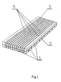
- Fig.1 presents the apparatus in accordance with the invention with elongated openings
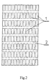
- Fig.2 presents the exemplary spacing of the supports of the apparatus
- Fig.3 presents an exemplary form of the apparatus, in the shape of a strip
- Fig.4 presents an exemplary form of the apparatus in the shape of a leg compress
- Fig.5 presents an exemplary form of the apparatus in the shape of a armband
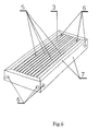
- Fig.6 presents the apparatus in the shape of a mattress
- Fig.7 presents the apparatus in the shape of a mattress (axonometric section).
- the apparatus for stimulating the physiological processes of living organisms in the shape of a flat rectangular prism, consists of supports 1. to which there are attached electromagnetic wave emitters.
- the supports 1 are permanently connected to the bottom part of the thinly woven material 2.
- the upper plane of the thinly woven material 2 is lined with an insulating material that has elongated openings, in which there are installed light wave emitters 5.
- the variant of the apparatus in the form of a band has a feeder cable and control device 9.
- the variants of the apparatus in the form of an armband and headband are connected by cable 10 with the feeder cable and control device 9.
- the variant of the apparatus in the shape of a mattress has light wave emitters 5 fitted in the openings of the insulating material 3. Openings 6 are situated in the side walls of the mattress-shaped apparatus and at one of the shorter edges, in the thermal insulating material.
- the electromagnetic wave emitters 4 are installed between the two fabrics 8.
Landscapes
- Health & Medical Sciences (AREA)
- Engineering & Computer Science (AREA)
- Biomedical Technology (AREA)
- Nuclear Medicine, Radiotherapy & Molecular Imaging (AREA)
- Radiology & Medical Imaging (AREA)
- Life Sciences & Earth Sciences (AREA)
- Animal Behavior & Ethology (AREA)
- General Health & Medical Sciences (AREA)
- Public Health (AREA)
- Veterinary Medicine (AREA)
- Pathology (AREA)
- Neurology (AREA)
- Radiation-Therapy Devices (AREA)
- Magnetic Treatment Devices (AREA)
Claims (13)
- Gerät in Quaderform zur Stimulation der physiologischen Prozesse von lebenden Organismen, das zwischen dem Boden und der oberen Fläche über freien Raum für die Ermöglichung der Emission der elektromagnetischen und thermischen Wellen verfügt, an dessen Boden zwischen zwei für Wärmestrahlung durchlässigen Geweben Spulen installiert sind, und das dadurch gekennzeichnet ist, dass es eine durch zwei Parallelen oder den Parallelen angenäherte Ebenen beschränkte räumliche Form hat und aus einer Reihe von Auflagern (1) mit einheitlicher Höhe und mit beliebiger Form fest mit der oberen Fläche des Gerätes verbunden sind, die ein thermischer Isolierstoff mit dünner Bindung (2) ist, der von oben mit thermischem Isolierstoff (3) ausgekleidet ist, wobei der thermische Isolierstoff (3) beliebig angeordnete Öffnungen in beliebiger Form aufweist, in denen Lichtwellenstrahler (5) montiert sind, die Lichtwellen mit der Länge von 380 nm bis 630 nm, mit generierter Frequenz von 0,5 MHz bis 100 MHz und der Leistung von 100 mW ausstrahlt, wobei die in dem unteren Teil der Auflager eingebauten Strahler elektromagnetischer Wellen (4) so ausgewählt sind, dass es in Höhe der oberen Fläche des Gerätes, etwas über dem montierten Stoff mit dünner Bindung oder auf seinem Niveau, an jedem beliebigen Punkt der oberen Fläche des Gerätes ein beliebiger Wert der elektromagnetischen Induktion im Bereich vom 0,001 µT bis 80 µT und mit Frequenz von 10 Hz bis 100 Hz erzielt werden kann, die gleichzeitig eine bestimmte Wärmemenge emittieren, wobei das Gerät mit dem Wechselstrom mit der Grenzspannung im Bereich von 6V bis 24V eingespeist wird, und an das Steuerungssystem des Gerätes angeschlossen ist, das mit dem Frequenzenerator für die emittierten Lichtwellen ausgerüstet ist.
- Das Gerät ist, gemäß Anspruch 1, dadurch gekennzeichnet, dass die Strahler der elektromagnetischen Wellen (4) Wellen mit der elektromagnetischen Induktion im Bereich von 0,01 µT do 5,00 µT und mit der Frequenz von 50 Hz bis 60 Hz emittieren.
- Das Gerät ist, gemäß Anspruch 1, dadurch gekennzeichnet, dass der Stoff mit dünner Bindung (2) ein Netz aus Glasfasern oder einem anderen geeigneten Material ist, das die Entwicklung von Bakterien hemmt.
- Das Gerät ist, gemäß Anspruch 1, dadurch gekennzeichnet, dass der thermische Isolierstoff (3) elastisch ist und bakterizide und fungizide Eigenschaften aufweist.
- Das Gerät ist, gemäß Anspruch 1, dadurch gekennzeichnet, dass die beliebig in den thermischen Isolierstoff (3) angebrachten Öffnungen die Form von länglichen Schlitzen oder Kreisen und/oder Ellipsen mit unterschiedlichem oder einheitlichem Durchmesser haben, oder Schlitzen um die regelmäßigen Vielecke bilden, die in Form der "Bienenwabe" verlegt sind.
- Das Gerät ist, gemäß Anspruch 5, dadurch gekennzeichnet, dass die in den Schlitzen oder Öffnungen des thermischen Isolierstoffes (3) angebrachten Lichtwellenstrahler (5) die Lichtwellen mit generierter Frequenz von 0,8 MHz bis 1,2 MHz emittieren und in Reihen oder in Bündeln in beliebiger Anzahl angeordnet sind.
- Das Gerät ist, gemäß Anspruch 6, dadurch gekennzeichnet, dass die Anzahl der Lichtwellenstrahler (5) sich insgesamt zwischen 1 bis 8 bewegt.
- Das Gerät ist, gemäß Anspruch 7, dadurch gekennzeichnet, dass die Lichtwellenstrahler (5) auf einem Punkt in Höhe von 2/3 der Länge des Gerätes oder im mittleren Teil seiner oberen, offenen Fläche angebracht sind.
- Das Gerät ist, gemäß Anspruch 6, dadurch gekennzeichnet, dass die Lichtwellenstrahler (5) Lichtdioden mit der Leistung von 20 mW bis 50 mW sind.
- Das Gerät ist, gemäß Anspruch 1, dadurch gekennzeichnet, dass es die Form von Gürteln, Kompressen oder derartigem hat, die an bestimmten Körperteilen des lebenden Organismus befestigt werden oder für die Auskleidung anderer Gegenstände zum Sitzen oder Liegen dienen.
- Das Gerät ist, gemäß Anspruch 1, dadurch gekennzeichnet, dass es eine Matratze ist, derer Boden mit den seitlichen Wänden fest verbunden ist, wobei der Boden und die seitlichen Wände an der Innenseite mit einem dichten, luftundurchlässigen Stoff ausgekleidet sind, an der Innenseite des Matratzebodens hingegen oder gleich über dem Matratzeboden die Strahler der elektromagnetischen Wellen (4) und der Wärmeemission montiert sind, die obere Fläche des Gerätes ist hingegen ein Stoff mit dünner Bindung (2), der von oben mit thermischem Isolierstoff (3) ausgekleidet ist, der beliebig angeordnete Öffnungen beliebiger Form hat, in denen die Lichtwellenstrahler (5) angebracht sind, wobei die seitlichen Wände über Lüftungsöffnungen (6) verfügen, die von hand oder automatisch geschlossen und geöffnet werden und der freie Raum innerhalb des Gerätes zwischen dem Boden und dem Stoff mit dünner Bindung über eine Feder unetrstützte Polsterkonstruktion verfügt, bei der um die Polsterfedern ein Freiraum gelassen wurde.
- Das Gerät ist, gemäß Anspruch 11, dadurch gekennzeichnet, dass die Strahler der elektromagnetischen Wellen (4) Spulen und/oder Spulensätze sind.
- Das Gerät ist, gemäß Anspruch 12, dadurch gekennzeichnet, dass die Strahler der elektromagnetischen Wellen (4) unter/oder zwischen zwei Geweben oder Stoffen (8) angebracht sind, die thermische Strahlung durchlassen.
Applications Claiming Priority (3)
| Application Number | Priority Date | Filing Date | Title |
|---|---|---|---|
| PL02357149A PL357149A1 (en) | 2002-11-15 | 2002-11-15 | Apparatus for stimulation of physiological processes in live organisms using light waves, electromagnetic induction and thermal interaction |
| PL35714902 | 2002-11-15 | ||
| PCT/PL2003/000026 WO2004045715A1 (en) | 2002-11-15 | 2003-03-17 | Apparatus for stimulating the physiological processes of living organism using light waves electromagnetic induction and thermal interaction |
Publications (2)
| Publication Number | Publication Date |
|---|---|
| EP1567226A1 EP1567226A1 (de) | 2005-08-31 |
| EP1567226B1 true EP1567226B1 (de) | 2008-08-20 |
Family
ID=32322592
Family Applications (1)
| Application Number | Title | Priority Date | Filing Date |
|---|---|---|---|
| EP03713112A Expired - Lifetime EP1567226B1 (de) | 2002-11-15 | 2003-03-17 | Gerät zur stimulation der physiologischen prozesse des lebenden organismus mit lichtwellen, elektromagnetischer induktion und thermischer interaktion |
Country Status (13)
| Country | Link |
|---|---|
| US (1) | US20060235491A1 (de) |
| EP (1) | EP1567226B1 (de) |
| JP (1) | JP2006525103A (de) |
| CN (1) | CN2930749Y (de) |
| AT (1) | ATE405322T1 (de) |
| AU (1) | AU2003217089B2 (de) |
| CA (1) | CA2505948A1 (de) |
| DE (1) | DE60323128D1 (de) |
| PL (1) | PL357149A1 (de) |
| RU (1) | RU2311208C2 (de) |
| UA (1) | UA80169C2 (de) |
| WO (1) | WO2004045715A1 (de) |
| ZA (1) | ZA200503751B (de) |
Families Citing this family (6)
| Publication number | Priority date | Publication date | Assignee | Title |
|---|---|---|---|---|
| US20060205994A1 (en) * | 2005-03-08 | 2006-09-14 | Sunnen Gerard V | Vibrational delta and theta brain wave induction apparatus and method for the stimulation of sleep |
| PL2665516T3 (pl) | 2011-01-21 | 2016-01-29 | Cosmosoft | Urządzenie do emisji pola magnetycznego |
| JP2013022115A (ja) * | 2011-07-19 | 2013-02-04 | Takemoriko Hayashi | 健康・美容増進装置 |
| ITFI20110179A1 (it) * | 2011-08-12 | 2013-02-13 | Vania Fontani | Metodo per il trattamento in vitro di cellule differenziate o indifferenziate mediante l?applicazione di campi elettromagnetici |
| WO2016209834A1 (en) | 2015-06-22 | 2016-12-29 | Quantum Dynamics L.L.C. | Device for providing body temperature regulation and/or therapeutic light directed to vasculature |
| IT201800004007A1 (it) * | 2018-03-27 | 2019-09-27 | Gabriele Alberton | Dispositivo magnetoterapico ad efficacia potenziata |
Family Cites Families (15)
| Publication number | Priority date | Publication date | Assignee | Title |
|---|---|---|---|---|
| EP0076074A1 (de) * | 1981-09-24 | 1983-04-06 | BENTALL, Richard Hugh Cameron | Vorrichtung zum Anlegen eines hochfrequenten elektromagnetischen Feldes an lebendes Gewebe zur Unterstützung von dessen Heilung |
| US4685462A (en) * | 1985-08-21 | 1987-08-11 | The United States Of America As Represented By The Secretary Of The Navy | Method and apparatus for treatment of hypothermia by electromagnetic energy |
| US5000178A (en) * | 1986-05-23 | 1991-03-19 | Lti Biomedical, Inc. | Shielded electromagnetic transducer |
| JPH05329217A (ja) | 1992-06-01 | 1993-12-14 | World Nikken:Kk | 電気磁気治療装置 |
| US5344384A (en) * | 1992-12-11 | 1994-09-06 | Electromagnetic Bracing Systems, Inc. | Magnetotherapy apparatus |
| AU1380095A (en) | 1994-01-21 | 1995-08-08 | Erik Larsen | Device for stimulating body cells by electromagnetic radiation |
| RU2124910C1 (ru) * | 1997-04-21 | 1999-01-20 | Шошенский Аркадий Михайлович | Устройство для терапии |
| RU2145247C1 (ru) * | 1998-04-10 | 2000-02-10 | Жаров Владимир Павлович | Фотоматричное терапевтическое устройство для лечения протяженных патологий |
| RU2153866C1 (ru) * | 1999-12-28 | 2000-08-10 | Михайлов Владимир Александрович | Устройство для фототермокриотерапии и способ его использования |
| US6602275B1 (en) * | 2000-09-18 | 2003-08-05 | Jana Sullivan | Device and method for therapeutic treatment of living organisms |
| US7101384B2 (en) * | 2001-03-08 | 2006-09-05 | Tru-Light Corporation | Light processing of selected body components |
| WO2002087700A1 (en) * | 2001-04-26 | 2002-11-07 | The Procter & Gamble Company | Method, kit and device for the treatment of cosmetic skin conditions |
| US20030002297A1 (en) * | 2001-06-26 | 2003-01-02 | Nemtsev Igor Z. | Light bracelet and brace |
| US20030032900A1 (en) * | 2001-08-08 | 2003-02-13 | Engii (2001) Ltd. | System and method for facial treatment |
| US6899667B2 (en) * | 2002-10-21 | 2005-05-31 | Paul F. Becker | Method and apparatus for the treatment of physical and mental disorders with low frequency, low flux density magnetic fields |
-
2002
- 2002-11-15 PL PL02357149A patent/PL357149A1/xx not_active IP Right Cessation
-
2003
- 2003-03-17 AT AT03713112T patent/ATE405322T1/de not_active IP Right Cessation
- 2003-03-17 EP EP03713112A patent/EP1567226B1/de not_active Expired - Lifetime
- 2003-03-17 UA UAA200505897A patent/UA80169C2/uk unknown
- 2003-03-17 DE DE60323128T patent/DE60323128D1/de not_active Expired - Fee Related
- 2003-03-17 RU RU2005118986/14A patent/RU2311208C2/ru not_active IP Right Cessation
- 2003-03-17 WO PCT/PL2003/000026 patent/WO2004045715A1/en not_active Ceased
- 2003-03-17 CN CNU039000125U patent/CN2930749Y/zh not_active Expired - Fee Related
- 2003-03-17 JP JP2006520527A patent/JP2006525103A/ja active Pending
- 2003-03-17 US US10/534,563 patent/US20060235491A1/en not_active Abandoned
- 2003-03-17 AU AU2003217089A patent/AU2003217089B2/en not_active Ceased
- 2003-03-17 CA CA002505948A patent/CA2505948A1/en not_active Abandoned
-
2005
- 2005-05-10 ZA ZA200503751A patent/ZA200503751B/xx unknown
Also Published As
| Publication number | Publication date |
|---|---|
| AU2003217089A1 (en) | 2004-06-15 |
| UA80169C2 (en) | 2007-08-27 |
| WO2004045715A1 (en) | 2004-06-03 |
| US20060235491A1 (en) | 2006-10-19 |
| JP2006525103A (ja) | 2006-11-09 |
| ZA200503751B (en) | 2006-11-29 |
| PL357149A1 (en) | 2004-05-17 |
| CA2505948A1 (en) | 2004-06-03 |
| ATE405322T1 (de) | 2008-09-15 |
| WO2004045715A8 (en) | 2005-10-13 |
| RU2005118986A (ru) | 2006-02-10 |
| CN2930749Y (zh) | 2007-08-08 |
| RU2311208C2 (ru) | 2007-11-27 |
| DE60323128D1 (de) | 2008-10-02 |
| EP1567226A1 (de) | 2005-08-31 |
| AU2003217089B2 (en) | 2008-07-31 |
Similar Documents
| Publication | Publication Date | Title |
|---|---|---|
| JP7639069B2 (ja) | 低減された表面刺激および改善された治療深さのための磁気刺激コイルおよび強磁性コンポーネント | |
| CN104640602B (zh) | 便携式光疗装置 | |
| US5478303A (en) | Electromagnetic apparatus for use in therapy | |
| US8333756B2 (en) | Scalar laser therapy apparatus | |
| US11020610B2 (en) | Positioning device for use in therapeutic treatment | |
| AU661789B2 (en) | Magnetic field induction multi-pulse therapy | |
| EP4616900A1 (de) | Magnetische stimulationsvorrichtung vom helmtyp | |
| KR20080092534A (ko) | 뇌파를 주요치료정보로 사용하는 저주파 자기물리치료장치 | |
| KR101725149B1 (ko) | 광 자극 브래지어 | |
| AU2003217089B2 (en) | Apparatus for stimulating the physiological processes of living organism using light waves electromagnetic induction and thermal interaction | |
| US7258658B2 (en) | Method and apparatus for stimulating cellular regeneration in a patient | |
| JP5684434B1 (ja) | 電位変動式医療機器 | |
| US20080139872A1 (en) | Pad for stimulating cellular regeneration in a patient | |
| GB2270000A (en) | Magnetic field induction multi - pulse therapy. | |
| IE901144A1 (en) | Electromagnetic apparatus for use in therapy | |
| US7722522B2 (en) | Brace providing focused energy for medical therapy | |
| JPS5832777A (ja) | 遠赤外線照射治療装置 | |
| KR101119936B1 (ko) | 구동 가능한 발열부를 갖는 온열 매트 | |
| JP3200432U (ja) | 電位変動型量子治療器 | |
| CZ18933U1 (cs) | Terapeutická matrace | |
| KR20070017737A (ko) | 의료용 광원 조사장치 | |
| AU2017101105A4 (en) | Treatment method and apparatus using light | |
| Attili | Design and application of cylindrical and conical focusing structures to obtain increased efficiency in microwave hyperthermia systems for cancer treatment | |
| KR100906132B1 (ko) | 원적외선과 음이온을 발산하는 열풍경대 | |
| CN118871169A (zh) | 包括多个线圈的头盔式磁刺激装置 |
Legal Events
| Date | Code | Title | Description |
|---|---|---|---|
| PUAI | Public reference made under article 153(3) epc to a published international application that has entered the european phase |
Free format text: ORIGINAL CODE: 0009012 |
|
| 17P | Request for examination filed |
Effective date: 20050610 |
|
| AK | Designated contracting states |
Kind code of ref document: A1 Designated state(s): AT BE BG CH CY CZ DE DK EE ES FI FR GB GR HU IE IT LI LU MC NL PT RO SE SI SK TR |
|
| AX | Request for extension of the european patent |
Extension state: AL LT LV MK |
|
| DAX | Request for extension of the european patent (deleted) | ||
| GRAP | Despatch of communication of intention to grant a patent |
Free format text: ORIGINAL CODE: EPIDOSNIGR1 |
|
| GRAS | Grant fee paid |
Free format text: ORIGINAL CODE: EPIDOSNIGR3 |
|
| GRAA | (expected) grant |
Free format text: ORIGINAL CODE: 0009210 |
|
| AK | Designated contracting states |
Kind code of ref document: B1 Designated state(s): AT BE BG CH CY CZ DE DK EE ES FI FR GB GR HU IE IT LI LU MC NL PT RO SE SI SK TR |
|
| REG | Reference to a national code |
Ref country code: GB Ref legal event code: FG4D |
|
| REG | Reference to a national code |
Ref country code: CH Ref legal event code: EP |
|
| REG | Reference to a national code |
Ref country code: IE Ref legal event code: FG4D |
|
| REF | Corresponds to: |
Ref document number: 60323128 Country of ref document: DE Date of ref document: 20081002 Kind code of ref document: P |
|
| PG25 | Lapsed in a contracting state [announced via postgrant information from national office to epo] |
Ref country code: ES Free format text: LAPSE BECAUSE OF FAILURE TO SUBMIT A TRANSLATION OF THE DESCRIPTION OR TO PAY THE FEE WITHIN THE PRESCRIBED TIME-LIMIT Effective date: 20081201 Ref country code: NL Free format text: LAPSE BECAUSE OF FAILURE TO SUBMIT A TRANSLATION OF THE DESCRIPTION OR TO PAY THE FEE WITHIN THE PRESCRIBED TIME-LIMIT Effective date: 20080820 |
|
| PG25 | Lapsed in a contracting state [announced via postgrant information from national office to epo] |
Ref country code: FI Free format text: LAPSE BECAUSE OF FAILURE TO SUBMIT A TRANSLATION OF THE DESCRIPTION OR TO PAY THE FEE WITHIN THE PRESCRIBED TIME-LIMIT Effective date: 20080820 Ref country code: SI Free format text: LAPSE BECAUSE OF FAILURE TO SUBMIT A TRANSLATION OF THE DESCRIPTION OR TO PAY THE FEE WITHIN THE PRESCRIBED TIME-LIMIT Effective date: 20080820 Ref country code: AT Free format text: LAPSE BECAUSE OF FAILURE TO SUBMIT A TRANSLATION OF THE DESCRIPTION OR TO PAY THE FEE WITHIN THE PRESCRIBED TIME-LIMIT Effective date: 20080820 |
|
| PG25 | Lapsed in a contracting state [announced via postgrant information from national office to epo] |
Ref country code: BE Free format text: LAPSE BECAUSE OF FAILURE TO SUBMIT A TRANSLATION OF THE DESCRIPTION OR TO PAY THE FEE WITHIN THE PRESCRIBED TIME-LIMIT Effective date: 20080820 |
|
| PG25 | Lapsed in a contracting state [announced via postgrant information from national office to epo] |
Ref country code: DK Free format text: LAPSE BECAUSE OF FAILURE TO SUBMIT A TRANSLATION OF THE DESCRIPTION OR TO PAY THE FEE WITHIN THE PRESCRIBED TIME-LIMIT Effective date: 20080820 Ref country code: BG Free format text: LAPSE BECAUSE OF FAILURE TO SUBMIT A TRANSLATION OF THE DESCRIPTION OR TO PAY THE FEE WITHIN THE PRESCRIBED TIME-LIMIT Effective date: 20081120 |
|
| PG25 | Lapsed in a contracting state [announced via postgrant information from national office to epo] |
Ref country code: SK Free format text: LAPSE BECAUSE OF FAILURE TO SUBMIT A TRANSLATION OF THE DESCRIPTION OR TO PAY THE FEE WITHIN THE PRESCRIBED TIME-LIMIT Effective date: 20080820 Ref country code: RO Free format text: LAPSE BECAUSE OF FAILURE TO SUBMIT A TRANSLATION OF THE DESCRIPTION OR TO PAY THE FEE WITHIN THE PRESCRIBED TIME-LIMIT Effective date: 20080820 Ref country code: PT Free format text: LAPSE BECAUSE OF FAILURE TO SUBMIT A TRANSLATION OF THE DESCRIPTION OR TO PAY THE FEE WITHIN THE PRESCRIBED TIME-LIMIT Effective date: 20090120 |
|
| PGFP | Annual fee paid to national office [announced via postgrant information from national office to epo] |
Ref country code: CZ Payment date: 20090206 Year of fee payment: 7 |
|
| PLBE | No opposition filed within time limit |
Free format text: ORIGINAL CODE: 0009261 |
|
| STAA | Information on the status of an ep patent application or granted ep patent |
Free format text: STATUS: NO OPPOSITION FILED WITHIN TIME LIMIT |
|
| 26N | No opposition filed |
Effective date: 20090525 |
|
| PG25 | Lapsed in a contracting state [announced via postgrant information from national office to epo] |
Ref country code: EE Free format text: LAPSE BECAUSE OF FAILURE TO SUBMIT A TRANSLATION OF THE DESCRIPTION OR TO PAY THE FEE WITHIN THE PRESCRIBED TIME-LIMIT Effective date: 20080820 |
|
| PG25 | Lapsed in a contracting state [announced via postgrant information from national office to epo] |
Ref country code: IT Free format text: LAPSE BECAUSE OF FAILURE TO SUBMIT A TRANSLATION OF THE DESCRIPTION OR TO PAY THE FEE WITHIN THE PRESCRIBED TIME-LIMIT Effective date: 20080820 |
|
| PG25 | Lapsed in a contracting state [announced via postgrant information from national office to epo] |
Ref country code: MC Free format text: LAPSE BECAUSE OF NON-PAYMENT OF DUE FEES Effective date: 20090331 |
|
| REG | Reference to a national code |
Ref country code: CH Ref legal event code: PL |
|
| GBPC | Gb: european patent ceased through non-payment of renewal fee |
Effective date: 20090317 |
|
| REG | Reference to a national code |
Ref country code: FR Ref legal event code: ST Effective date: 20091130 |
|
| REG | Reference to a national code |
Ref country code: IE Ref legal event code: MM4A |
|
| PG25 | Lapsed in a contracting state [announced via postgrant information from national office to epo] |
Ref country code: LI Free format text: LAPSE BECAUSE OF NON-PAYMENT OF DUE FEES Effective date: 20090331 Ref country code: SE Free format text: LAPSE BECAUSE OF FAILURE TO SUBMIT A TRANSLATION OF THE DESCRIPTION OR TO PAY THE FEE WITHIN THE PRESCRIBED TIME-LIMIT Effective date: 20081120 Ref country code: DE Free format text: LAPSE BECAUSE OF NON-PAYMENT OF DUE FEES Effective date: 20091001 Ref country code: CH Free format text: LAPSE BECAUSE OF NON-PAYMENT OF DUE FEES Effective date: 20090331 Ref country code: IE Free format text: LAPSE BECAUSE OF NON-PAYMENT OF DUE FEES Effective date: 20090317 |
|
| PG25 | Lapsed in a contracting state [announced via postgrant information from national office to epo] |
Ref country code: GB Free format text: LAPSE BECAUSE OF NON-PAYMENT OF DUE FEES Effective date: 20090317 Ref country code: FR Free format text: LAPSE BECAUSE OF NON-PAYMENT OF DUE FEES Effective date: 20091123 |
|
| PG25 | Lapsed in a contracting state [announced via postgrant information from national office to epo] |
Ref country code: GR Free format text: LAPSE BECAUSE OF FAILURE TO SUBMIT A TRANSLATION OF THE DESCRIPTION OR TO PAY THE FEE WITHIN THE PRESCRIBED TIME-LIMIT Effective date: 20081121 |
|
| PG25 | Lapsed in a contracting state [announced via postgrant information from national office to epo] |
Ref country code: CZ Free format text: LAPSE BECAUSE OF NON-PAYMENT OF DUE FEES Effective date: 20100317 |
|
| PG25 | Lapsed in a contracting state [announced via postgrant information from national office to epo] |
Ref country code: LU Free format text: LAPSE BECAUSE OF NON-PAYMENT OF DUE FEES Effective date: 20090317 |
|
| PG25 | Lapsed in a contracting state [announced via postgrant information from national office to epo] |
Ref country code: HU Free format text: LAPSE BECAUSE OF FAILURE TO SUBMIT A TRANSLATION OF THE DESCRIPTION OR TO PAY THE FEE WITHIN THE PRESCRIBED TIME-LIMIT Effective date: 20090221 |
|
| PG25 | Lapsed in a contracting state [announced via postgrant information from national office to epo] |
Ref country code: TR Free format text: LAPSE BECAUSE OF FAILURE TO SUBMIT A TRANSLATION OF THE DESCRIPTION OR TO PAY THE FEE WITHIN THE PRESCRIBED TIME-LIMIT Effective date: 20080820 |
|
| PG25 | Lapsed in a contracting state [announced via postgrant information from national office to epo] |
Ref country code: CY Free format text: LAPSE BECAUSE OF FAILURE TO SUBMIT A TRANSLATION OF THE DESCRIPTION OR TO PAY THE FEE WITHIN THE PRESCRIBED TIME-LIMIT Effective date: 20080820 |