EP1566860A1 - Electrical connection structure for conductor formed on glass surface - Google Patents
Electrical connection structure for conductor formed on glass surface Download PDFInfo
- Publication number
- EP1566860A1 EP1566860A1 EP03811898A EP03811898A EP1566860A1 EP 1566860 A1 EP1566860 A1 EP 1566860A1 EP 03811898 A EP03811898 A EP 03811898A EP 03811898 A EP03811898 A EP 03811898A EP 1566860 A1 EP1566860 A1 EP 1566860A1
- Authority
- EP
- European Patent Office
- Prior art keywords
- conductor
- glass surface
- terminal
- connection member
- cover member
- Prior art date
- Legal status (The legal status is an assumption and is not a legal conclusion. Google has not performed a legal analysis and makes no representation as to the accuracy of the status listed.)
- Granted
Links
Images

Classifications
-
- H—ELECTRICITY
- H01—ELECTRIC ELEMENTS
- H01R—ELECTRICALLY-CONDUCTIVE CONNECTIONS; STRUCTURAL ASSOCIATIONS OF A PLURALITY OF MUTUALLY-INSULATED ELECTRICAL CONNECTING ELEMENTS; COUPLING DEVICES; CURRENT COLLECTORS
- H01R4/00—Electrically-conductive connections between two or more conductive members in direct contact, i.e. touching one another; Means for effecting or maintaining such contact; Electrically-conductive connections having two or more spaced connecting locations for conductors and using contact members penetrating insulation
- H01R4/28—Clamped connections, spring connections
- H01R4/48—Clamped connections, spring connections utilising a spring, clip, or other resilient member
-
- H—ELECTRICITY
- H01—ELECTRIC ELEMENTS
- H01R—ELECTRICALLY-CONDUCTIVE CONNECTIONS; STRUCTURAL ASSOCIATIONS OF A PLURALITY OF MUTUALLY-INSULATED ELECTRICAL CONNECTING ELEMENTS; COUPLING DEVICES; CURRENT COLLECTORS
- H01R13/00—Details of coupling devices of the kinds covered by groups H01R12/70 or H01R24/00 - H01R33/00
- H01R13/02—Contact members
- H01R13/22—Contacts for co-operating by abutting
- H01R13/24—Contacts for co-operating by abutting resilient; resiliently-mounted
- H01R13/2442—Contacts for co-operating by abutting resilient; resiliently-mounted with a single cantilevered beam
-
- H—ELECTRICITY
- H01—ELECTRIC ELEMENTS
- H01R—ELECTRICALLY-CONDUCTIVE CONNECTIONS; STRUCTURAL ASSOCIATIONS OF A PLURALITY OF MUTUALLY-INSULATED ELECTRICAL CONNECTING ELEMENTS; COUPLING DEVICES; CURRENT COLLECTORS
- H01R13/00—Details of coupling devices of the kinds covered by groups H01R12/70 or H01R24/00 - H01R33/00
- H01R13/02—Contact members
- H01R13/20—Pins, blades, or sockets shaped, or provided with separate member, to retain co-operating parts together
-
- H—ELECTRICITY
- H01—ELECTRIC ELEMENTS
- H01R—ELECTRICALLY-CONDUCTIVE CONNECTIONS; STRUCTURAL ASSOCIATIONS OF A PLURALITY OF MUTUALLY-INSULATED ELECTRICAL CONNECTING ELEMENTS; COUPLING DEVICES; CURRENT COLLECTORS
- H01R4/00—Electrically-conductive connections between two or more conductive members in direct contact, i.e. touching one another; Means for effecting or maintaining such contact; Electrically-conductive connections having two or more spaced connecting locations for conductors and using contact members penetrating insulation
- H01R4/28—Clamped connections, spring connections
- H01R4/50—Clamped connections, spring connections utilising a cam, wedge, cone or ball also combined with a screw
- H01R4/5066—Clamped connections, spring connections utilising a cam, wedge, cone or ball also combined with a screw mounted in an insulating housing having a cover providing clamping force
-
- H—ELECTRICITY
- H01—ELECTRIC ELEMENTS
- H01R—ELECTRICALLY-CONDUCTIVE CONNECTIONS; STRUCTURAL ASSOCIATIONS OF A PLURALITY OF MUTUALLY-INSULATED ELECTRICAL CONNECTING ELEMENTS; COUPLING DEVICES; CURRENT COLLECTORS
- H01R13/00—Details of coupling devices of the kinds covered by groups H01R12/70 or H01R24/00 - H01R33/00
- H01R13/62—Means for facilitating engagement or disengagement of coupling parts or for holding them in engagement
- H01R13/627—Snap or like fastening
- H01R13/6271—Latching means integral with the housing
- H01R13/6272—Latching means integral with the housing comprising a single latching arm
-
- H—ELECTRICITY
- H01—ELECTRIC ELEMENTS
- H01R—ELECTRICALLY-CONDUCTIVE CONNECTIONS; STRUCTURAL ASSOCIATIONS OF A PLURALITY OF MUTUALLY-INSULATED ELECTRICAL CONNECTING ELEMENTS; COUPLING DEVICES; CURRENT COLLECTORS
- H01R2201/00—Connectors or connections adapted for particular applications
- H01R2201/02—Connectors or connections adapted for particular applications for antennas
Definitions
- the present invention relates to an electrical connection structure for a conductor formed on a glass surface, for electrically connecting a conductor formed on a glass surface with a lead wire.
- an antenna function for receiving e.g. AM, FM or TV waves, or a defog function for defogging the window glass is added by forming a baked silver paste on the glass surface.
- a bus bar portion made of a baked silver paste In order to exhibit these functions, it is necessary to supply electricity via a bus bar portion made of a baked silver paste.
- the supply of electricity is achieved by soldering a terminal having a shape shown as PA or PV type flat-type male terminal for automobiles defined by JIS-D5403 to the bus bar portion, and by connecting a connector connected with a lead wire, with the terminal.
- Fig. 5 is a perspective view showing a conventional structure that a terminal 43 is soldered to a baked silver paste 2 and connected with a lead wire 6.
- the baked silver paste 2 and the lead wire 6 can be connected by connecting a connector 7 with the lead wire 6 and connecting the connector 7 with the terminal 43. Further, by pressing a switch 18 provided on the connector 7, the connector 7 can be disconnected from the terminal 43.
- solder used for a window glass for automobiles usually contains lead, much work is needed in treating the solder containing lead at a time of disposing the glass.
- ELV End Life of Vehicle
- WHEE&RoHS Wood Electrical and Electronic Equipment & Restriction of the use of certain Hazardous Substances in electrical and electronic equipment
- the terminal 43 since the terminal 43 is attached to the bus bar portion in a bare state, it affects the external appearance and it is requested to improve the design.
- U.S. Patent No. 4707591 discloses a method of pressing a bus bar portion of a glass surface against a contactor attached to a body-flange of an automobile and having a coil spring, to strongly contact the contactor with the bus bar portion by a reaction force of the coil spring so as to electrically connect them.
- JP-A-10-40977 discloses a method of bonding a base member to a bus bar portion on a glass surface, making an intervening terminal contact with the bus bar portion, placing a pressing member on the intervening terminal and fitting a cover member to the base member, so that by a pressing force of the pressing member, the intervening terminal is pressed against and held by the bus bar portion, to obtain an electrical connection with the bus bar portion.
- JP-A-10-40977 does not have the problem as in the invention described in the specification of U.S. Patent No. 4707591 since it does not use the body.
- the structure is composed of many parts and its assembly is complicated, it costs much, and insertion and pulling-off of the intervening terminal is difficult.
- an object of the present invention to provide an electrical connection structure for a conductor formed on a glass surface, which electrically connects the conductor formed on a glass surface with a lead wire without requiring soldering, and which comprises a small number of parts, and achieves space-saving and low cost.
- the present invention provides, in order to solve the above problems, an electrical connection structure for a conductor formed on a glass surface, comprising a conductor formed on a glass surface, a cover member provided to cover at least a part of the conductor, forming a cavity between the cover member and the glass surface and having an insertion slot communicated with the cavity, and a connection member inserted into the insertion slot made of an electrically conductive material having elasticity, wherein the connection member presses the conductor by being elastically deformed in the cavity, whereby the connection member and the conductor are electrically connected.
- the present invention is based on an idea of providing a cover member on a glass surface, inserting a connection member into a cavity formed by the cover member so as to elastically deform the connection member and pressing a conductor formed on a glass surface with the connection member to make them contact electrically. Since the above-mentioned construction does not require soldering, various problems caused by employing solder can be solved, and exchange of the parts is easy.
- the cover member and the connection member have respectively a structure fitting or engaging with each other.
- connection member has elasticity and the other end of the connection member is a male type or female type terminal for a connector connected with a lead wire.
- connection member has a male type or female type terminal used conventionally, a conventional connector of a lead-wire-side can be used and no procurement of new parts or capital investment is necessary.
- connection member may be such that one end of the connection member has elasticity and the other end of the connection member is connected with a lead wire by caulking. If the connection member is directly connected with a lead wire, it is possible to reduce the number of parts and lower the cost.
- connection member to be in contact with the conductor is applied with a metal plating at the surface.
- the conductor is preferably of a baked silver paste, and the conductor is preferably formed on a window glass for automobiles. Since conductors made of a baked silver paste provided on many window glasses for automobiles, are connected with terminals by soldering, various problems due to employing of solder can be solved by applying the construction of the present invention.
- the present invention provides an electrical connection structure for a conductor on a glass surface, without employing solder.
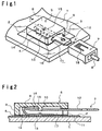
- Fig. 1 is a perspective view showing an example of Embodiment 1 employing a conventional connector of lead-wire-side as it is, and Fig. 2 is a cross sectional view along a line A-A' of Fig. 1.
- Embodiment 1 is constituted by a glass sheet 1 on which a conductor 2 is formed, a terminal member 3 made of an electrically conductive material, a cover member 5 pressing and holding by engagement the terminal member 3 and bonded to the glass surface 1 and/or the conductor 2 via an adhesive layer 4 so as to cover at least a part of the conductor 2, and a connector 7 for a terminal member 3 connected with an end of a lead wire 6.
- the cover member 5 bonded to the glass surface 1 and/or the conductor 2 via the adhesive layer 4, is constituted by a plate-shaped ceiling 8, a side wall 9 extending vertically from the periphery of the ceiling 8 and bonded to the glass surface 1 and/or the conductor 2 via an adhesive layer 4, a fitting portion 10 having a protrusion at the center of a surface of the ceiling 8 on a side of the side wall 9, and an insertion slot 11 formed by providing a gate-shaped notch on a part of the side wall 9 for inserting a terminal member 3 into the cover member 5.
- One end of the terminal member 3 is constituted by a terminal 12 of PA or PB type defined by JIS-D5403, and the other end of the terminal member 3 is constituted by a contact portion 13 to be in contact with the conductor 2, an elastic portion 14 having elasticity, and an insertion portion 16 having a fitting hole 15 for positioning the cover member 5 by being fitted to the fitting portion 10 of the cover member 5 and holding the cover member 5.
- the elasticity of the elastic portion 14 can be obtained by forming the insertion portion 16 to have a substantially acuate cross-sectional shape so as to have elasticity in a direction perpendicular to the conductor 2. Further, the height of the elastic portion 14 in a free space is higher than the height of the cavity 17 formed between the cover member 5 and the conductor 2.
- the elasticity of elastic portion 14 is used for connecting the terminal member 3 and the cover member 5.
- the insertion portion 16 is forced into the insertion slot 11 under elastic deformation of the elastic portion 14 until the height of the elastic portion 14 becomes lower than the height of the insertion slot 11, and the fitting portion 10 of the cover member 5 and the fitting hole 15 of the insertion portion 16 are fit and fixed together.
- the fitting serves as positioning, and the insertion portion 16 is pressed against the conductor 2 and the ceiling 8 by a reaction force of the elastic portion 14, whereby the insertion portion 16 does not disengage from the fitting with the cover member 5.
- the contact portion 13 is strongly pressed against the conductor 2 by the reaction force of the elastic portion 14, whereby a stable connection can be obtained. Therefore, by making the construction of the present invention, the conductor 2 and the terminal member 3 can be electrically connected without employing solder.
- the connector 7 on the side of the lead wire 6 is a female-type connector complying with JIS-D-5403 CW type plug receptacle for automobiles which has been conventionally used.
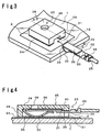
- Fig. 3 is a perspective view showing an example of Embodiment 2 not employing a conventional connector usable at the side of the lead wire
- Fig. 4 is a cross sectional view along a line B-B' of Fig. 3 in a state that the insertion member 36 is inserted.
- the same reference numerals are used for the parts in common with Fig. 1 or 2.
- Embodiment 2 is constituted by a glass sheet 1 on which a conductor 2 is formed, a terminal member 23 provided at an end of a lead wire 26 made of an electrically conductive material, and a cover member 25 for pressing and latching the terminal member 23, and bonded to the surface of the glass sheet 1 or/and the conductor 2 via an adhesive layer 24.
- the cover member 25 bonded to the surface of the glass sheet 1 or/and the conductor 2 via the adhesive layer 24, is constituted by a plate-shaped ceiling 28, a side wall 29 vertically extending from the periphery of the ceiling 28 and bonded to the surface of the glass sheet 1 and/or the conductor 2 via the adhesive layer 24, a through hole 38 provided approximately at the center of the ceiling 28, an insertion slot 31 formed by providing a gate-shaped notch at a part of the side wall 29 and allowing insertion of the terminal member 23 into the cover member 25, and a cover-member-side engage portion 30 formed by making the height of the insertion slot 31 lower than the height of the cavity 37 formed between the cover member 25 and the glass sheet 1.
- One end of the terminal member 23 comprises an intermediate member 32 having at one end a caulking portion 39 to be connected with a lead wire by caulking and having a plate-shaped portion at the other end, and an insertion member 36 bonded to the plate-shaped portion of the intermediate member 32, which is constituted by a contact portion 33 to be in contact with the conductor 2 and an elastic portion 34 having elasticity. Further, the terminal member 23 has a terminal-side engage portion 35 having a step shape formed by bonding the insertion portion 36 and the intermediate portion 32.
- the elasticity of the elastic portion 34 can be obtained by forming the insertion member 36 to have a substantially acuate cross sectional shape so as to have elasticity in a vertical direction with respect to the conductor 2. Further, the height of the elastic member 34 in a free space is higher than the height of the cavity 37 formed between the cover member 25 and the conductor 2.
- the elasticity of the elastic portion 34 is used.
- the insertion member 36 is forced into the insertion slot 31 under elastic deformation of the elastic portion 34 until the height of the elastic portion 34 becomes lower than the height of the insertion slot 31, and the cover-member-side engage portion 30 and the terminal-side engage portion 35 are engaged together.
- the terminal member 23 is pressed against the conductor 2 and the ceiling 28 by the reaction force of the elastic portion 34, whereby it does not disengage from the fitting with the cover member 25.
- the contact portion 33 is strongly pressed against the conductor 2 by the reaction force of the elastic portion 34, which provides a stable connection. Therefore, according to the construction of the present invention, the conductor 2 and the terminal member 23 are electrically connected without using a solder.
- the shape and the size of the cover members 5 and 25 and the terminal members 3 and 23 are not limited to those described above.
- the external shapes of the cover members 5 and 25 may be round shapes to escape from an external force even if it is applied thereto, or to improve their design.
- the cover members 5 and 25 may be colored to improve their appearances.
- the cover members 5 and 25 may have a structure in which a plurality of the terminal members 3 or 23 can be inserted.
- the fitting and engaging structure of each of the cover members 5 and 25 and terminal members 2 and 23 are not limited to Embodiments 1 and 2.
- the material of the cover members 5 and 25 is not particularly limited and is determined considering the durability or adhesiveness with the adhesive material forming the adhesive layers 4 and 14.
- a polyamide resin is mentioned.
- the production process may be a cutting or an injection molding and not particularly limited.
- the adhesive layers 4 and 14 may, for example, be a double-sided adhesive material (double-sided tape), a thermosetting adhesive agent or a thermoplastic adhesive agent.
- double-sided adhesive material double-sided tape
- a thermosetting adhesive agent a thermoplastic adhesive agent.
- thermoplastic adhesive agent a thermoplastic adhesive agent.
- the thickness of the adhesive layer is determined considering the size of the terminal member 3 or 23 within a range in which the elasticity of the elastic portion 14 or 34 can be used.
- Material of the terminal members 3 and 23 are not particularly limited so long as it is an electrically conductive material.
- at least the contact portions 13 and 33 are preferably applied with plating of a metal such as gold, silver, tin or nickel.
- the contact portions 13 and 33 to be in contact with these conductors 2 are preferably applied with metal plating.
- metal plating it is preferred to consider the material of the conductor 2 and environmental impact at a time of disposal. In particular, when the conductor 2 is a conductor formed by baking a silver paste, silver plating is preferred.
- Example 1 is an example of implementing Embodiment 1
- Example 2 is an example of implementing Embodiment 2.
- a cover member 5 having the shape shown in Figs. 1 and 2 was made by cutting a polyamide resin having a size of 18 mm x 12 mm and a thickness of 4 mm. Further, as an adhesive layer 4, a double-sided adhesive tape (manufactured by Sumitomo 3M Limited) of 0.4 mm thick cut into a shape corresponding to the bonding surface of the cover member 5, was employed to bond the cover member 5 at a predetermined position of the conductor 2 formed by baking a silver paste on a glass sheet 1.
- a double-sided adhesive tape manufactured by Sumitomo 3M Limited
- the terminal member 3 comprises an insertion portion made of a beryllium copper of 0.3 mm thick and a terminal portion 12 made of a bronze of 0.8 mm thick welded to the insertion portion.
- the terminal portion 3 has a size complying with JIS-D5403 PA type male blade (with shoulders) for automobiles.
- the insertion portion has a width of 4.5 mm, a length of 10 mm and a height in a free space of 3.0 mm.
- the terminal member 3 was inserted into the insertion slot 11 by pushing the insertion portion 16 under elastic deformation of the elastic portion 14 until the height of the elastic portion 14 becomes lower than the height of the cover member 5 at the insertion slot 11, and until the fitting portion 10 of the cover member 5 and the fitting hole 15 of the insertion portion 16 were fit together to be fixed.
- the contact resistance between the conductor 2 and the terminal member 3 was measured and found it to be at most 0.005 ⁇ which was sufficient for practical use even as compared with conventional examples, and the contact resistance remained good even through an environmental test.
- a cover member 25 having the shape shown in Figs. 3 and 4 was made by cutting a polyamide resin having a size of 16 mm x 15 mm and a thickness of 2.6 mm. Further, as an adhesive layer 24, a double-sided adhesive tape (manufactured by Sumitomo 3M Limited) of 0.4 mm thick cut into a shape corresponding to the bonding surface of the cover member 25, was employed to bond the cover member 25 at a predetermined position of a conductor 2 formed by baking a silver paste on a glass sheet 1.
- the terminal member 23 comprises an insertion member made of a beryllium copper of 0.2 mm thick and a caulking portion 39 made of bronze of 0.3 mm thick welded to the insertion member.
- the insertion member has a width of 4.3 mm, a length of 10 mm and a height in a free space of 2.5 mm.
- the caulking portion 39 has a length of 10 mm, a width of about 3.5 mm and a height of about 3 mm when it is caulked together with a lead wire 26.
- the terminal member 23 was pushed into the insertion slot 31 by pushing the insertion member 36 under elastic deformation of the elastic portion 34 until the height of the elastic portion 34 became lower than the height of the cover member 25 at the insertion slot 31, and until the cover-member-side engage portion 30 and the terminal-side engage portion 35 were engaged together.
- the contact resistance between the conductor 2 and the terminal member 23 was measured and found it to be at most 0.005 ⁇ which was sufficient for practical use even as compared with conventional examples, and the contact resistance remained good even through an environmental test.
- the present invention provides the following effects.
- a cover member is bonded to a conductor in advance. Therefore, by simply inserting a terminal member, the terminal member can be pressed against the conductor due to the elasticity of the terminal member to realize a stable electrical connection. Further, since the structure is simple and constituted by a small number of parts, the work can be simplified, the cost can be kept low and space can be saved since the connection structure is small-sized.
Landscapes
- Connections Effected By Soldering, Adhesion, Or Permanent Deformation (AREA)
- Coupling Device And Connection With Printed Circuit (AREA)
Abstract
Description
- 1:
- Glass sheet
- 2:
- Conductor
- 3, 23:
- Terminal member
- 5, 25:
- Cover member
- 6, 26:
- Lead wire
- 7:
- Connector
- 10:
- Fitting portion
- 11, 31:
- Insertion slot
- 12:
- Terminal
- 13, 33:
- Contact portion
- 14, 34:
- Elastic portion
- 15:
- Fitting hole
- 16:
- Insertion portion
- 17, 37:
- Space
- 30:
- Engage portion
- 32:
- Intermediate member
- 35:
- Engage portion
- 36:
- Insertion member
- 38:
- Through hole
- 43:
- Terminal for soldering
Claims (7)
- An electrical connection structure for a conductor formed on a glass surface, comprising a conductor formed on a glass surface, a cover member provided to cover at least a part of the conductor, forming a cavity between the cover member and the glass surface and having an insertion slot communicated with the cavity, and a connection member inserted into the insertion slot made of an electrically conductive material having elasticity, wherein the connection member presses the conductor by being elastically deformed in the cavity whereby the connection member and the conductor are electrically connected.
- The electrical connection structure for a conductor formed on a glass surface according to Claim 1, wherein the cover member and the connection member have respectively a structure fitting or engaging with each other.
- The electrical connection structure for a conductor formed on a glass surface according to Claim 1 or 2, wherein one end of the connection member has elasticity and the other end of the connection member is a male type or female type terminal for a connector connected with a lead wire.
- The electrical connection structure for a conductor formed on a glass surface according to Claim 1 or 2, wherein one end of the connection member has elasticity and the other end of the connection member is connected with a lead wire by caulking.
- The electrical connecting structure for a conductor formed on a glass surface according to any one of Claims 1 to 4, wherein a contact portion of the connection member to be in contact with the conductor is applied with metal plating at the surface.
- The electrical connecting structure for a conductor formed on a glass surface according to any one of Claims 1 to 5, wherein the conductor is of a baked silver paste.
- The electrical connection structure for a conductor formed on a glass surface according to any one of Claims 1 to 6, wherein the conductor is formed on a window glass for automobiles.
Applications Claiming Priority (3)
| Application Number | Priority Date | Filing Date | Title |
|---|---|---|---|
| JP2002345747 | 2002-11-28 | ||
| JP2002345747 | 2002-11-28 | ||
| PCT/JP2003/014527 WO2004049511A1 (en) | 2002-11-28 | 2003-11-14 | Electrical connection structure for conductor formed on glass surface |
Publications (3)
| Publication Number | Publication Date |
|---|---|
| EP1566860A1 true EP1566860A1 (en) | 2005-08-24 |
| EP1566860A4 EP1566860A4 (en) | 2007-07-11 |
| EP1566860B1 EP1566860B1 (en) | 2016-01-20 |
Family
ID=32376024
Family Applications (1)
| Application Number | Title | Priority Date | Filing Date |
|---|---|---|---|
| EP03811898.0A Expired - Lifetime EP1566860B1 (en) | 2002-11-28 | 2003-11-14 | Electrical connection structure for conductor formed on glass surface |
Country Status (7)
| Country | Link |
|---|---|
| US (1) | US7059884B2 (en) |
| EP (1) | EP1566860B1 (en) |
| JP (1) | JPWO2004049511A1 (en) |
| KR (1) | KR101065232B1 (en) |
| CN (1) | CN100495821C (en) |
| AU (1) | AU2003302259A1 (en) |
| WO (1) | WO2004049511A1 (en) |
Cited By (8)
| Publication number | Priority date | Publication date | Assignee | Title |
|---|---|---|---|---|
| DE102009016353A1 (en) * | 2009-04-07 | 2010-10-14 | Few Fahrzeugelektrik Werk Gmbh & Co. Kg | Electric connecting contact for e.g. antenna provided at panel of vehicle, has angular side piece for forming flat plug device that is bent around bending area, where bending area runs parallel to longitudinal extension |
| EP2597729A1 (en) * | 2011-11-25 | 2013-05-29 | Japan Aviation Electronics Industry Limited | Wire-to-board connector |
| EP2405535A4 (en) * | 2009-03-06 | 2014-04-30 | Nippon Sheet Glass Co Ltd | Glass with terminal |
| WO2014177852A3 (en) * | 2013-04-30 | 2015-05-07 | Pilkington Group Limited | Glazing |
| EP2884589A4 (en) * | 2012-08-10 | 2016-04-13 | Asahi Glass Co Ltd | ELECTRICALLY CONNECTED STRUCTURE, GLASS PLATE CONNECTED WITH A TERMINAL COMPRISING SAID STRUCTURE, AND METHOD FOR MANUFACTURING GLASS PLATE TO WHICH THE TERMINAL IS CONNECTED |
| WO2017077025A1 (en) * | 2015-11-05 | 2017-05-11 | Jaguar Land Rover Limited | Vehicle earth point connector |
| EP3312937A4 (en) * | 2015-06-19 | 2019-02-27 | Nippon Sheet Glass Company, Limited | Glass plate module |
| WO2025114229A1 (en) * | 2023-11-29 | 2025-06-05 | Agc Glass Europe | A window glazing having an electrically conductive connector |
Families Citing this family (29)
| Publication number | Priority date | Publication date | Assignee | Title |
|---|---|---|---|---|
| US20060121796A1 (en) * | 2004-12-08 | 2006-06-08 | Siemens Corporation | Electric phase bus bar |
| CN101147297A (en) * | 2005-03-24 | 2008-03-19 | 旭硝子株式会社 | Wire connection structure of laminated glass and laminated glass having wire connection structure |
| JP4482476B2 (en) * | 2005-04-11 | 2010-06-16 | 北川工業株式会社 | Connector and opening window member |
| DE102005040812A1 (en) * | 2005-08-27 | 2007-03-15 | Few Fahrzeugelektrikwerk Gmbh & Co. Kg | Electrical connection and method for its connection to the window of a motor vehicle |
| JP5114045B2 (en) * | 2006-11-27 | 2013-01-09 | 日本電気株式会社 | Antenna device and portable radio terminal |
| JP4996306B2 (en) * | 2007-03-29 | 2012-08-08 | クラリオン株式会社 | Glass anti-fogging heater device and glass antenna device |
| US7497715B2 (en) * | 2007-06-11 | 2009-03-03 | Hon Hai Precision Ind. Co., Ltd. | Cable connector assembly for solar device |
| JP5593953B2 (en) * | 2010-08-20 | 2014-09-24 | 旭硝子株式会社 | Connecting member |
| CN102324643A (en) * | 2011-06-08 | 2012-01-18 | 贵州航天电器股份有限公司 | Detachable welded-type contact element |
| CN202262071U (en) * | 2011-09-13 | 2012-05-30 | 鸿富锦精密工业(深圳)有限公司 | Flexible circuit board |
| WO2013128161A1 (en) | 2012-02-29 | 2013-09-06 | Pilkington Group Limited | Bondable electrical connector and method of utilizing same |
| US9504174B2 (en) * | 2012-08-09 | 2016-11-22 | A. Raymond Et Cie | Electrical connector for attachment to vehicle glass |
| ES2683007T3 (en) * | 2012-08-29 | 2018-09-24 | Nexans | Procedure to cover moisture proof a joint between an electrical conductor and a contact element |
| US9793623B2 (en) * | 2012-09-29 | 2017-10-17 | Harumoto Technology (Shen Zhen) Co., Ltd. | Coaxial cable connector assembly and a receptor connector |
| JP6016126B2 (en) * | 2013-08-07 | 2016-10-26 | 住友電装株式会社 | Feeding cable routing structure to heating wire terminal |
| EP3239112A4 (en) * | 2014-12-24 | 2018-08-15 | Asahi Glass Company, Limited | Electric connection member and a laminate plate using same |
| JP6330689B2 (en) * | 2015-02-19 | 2018-05-30 | 株式会社オートネットワーク技術研究所 | Electrical contact pair and connector terminal pair |
| CA2984056C (en) * | 2015-05-05 | 2020-03-24 | Saint-Gobain Glass France | Pane with electrical connection element and connecting element attached thereto |
| JP6350876B2 (en) * | 2015-06-18 | 2018-07-04 | 株式会社オートネットワーク技術研究所 | connector |
| JP2017012526A (en) * | 2015-07-02 | 2017-01-19 | 株式会社ユニバーサルエンターテインメント | Game machine |
| JP2017012524A (en) * | 2015-07-02 | 2017-01-19 | 株式会社ユニバーサルエンターテインメント | Game machine |
| JP6753414B2 (en) * | 2015-11-05 | 2020-09-09 | Agc株式会社 | Electrical connection structure, glass plate with terminals, and manufacturing method of glass plate with terminals |
| US9960510B2 (en) * | 2016-05-18 | 2018-05-01 | J.S.T. Mfg. Co., Ltd. | Connector |
| US9997846B1 (en) * | 2017-02-21 | 2018-06-12 | Ford Global Technologies, Llc | Window electrical terminals |
| CN206712064U (en) * | 2017-05-25 | 2017-12-05 | 莫列斯有限公司 | High current connector and high current connection device |
| CN111226499B (en) * | 2017-10-23 | 2022-11-18 | 伊利诺斯工具制品有限公司 | High wattage solderless flexible connector for printed conductors |
| WO2019235266A1 (en) * | 2018-06-05 | 2019-12-12 | Agc株式会社 | Vehicle window glass with terminal |
| DE102020004282A1 (en) * | 2019-07-24 | 2021-01-28 | AGC lnc. | ELECTRICAL CONNECTION STRUCTURE |
| US20210043997A1 (en) * | 2019-08-05 | 2021-02-11 | Agc Automotive Americas R&D, Inc. | Window assembly with solderless electrical connector |
Family Cites Families (44)
| Publication number | Priority date | Publication date | Assignee | Title |
|---|---|---|---|---|
| GB1297227A (en) * | 1970-09-05 | 1972-11-22 | ||
| JPS50535Y1 (en) * | 1972-07-05 | 1975-01-09 | ||
| US4023008A (en) * | 1972-12-28 | 1977-05-10 | Saint-Gobain Industries | Terminal connection for electric heaters for vehicle windows |
| JPS50535A (en) | 1973-05-09 | 1975-01-07 | ||
| IT1008823B (en) * | 1974-02-11 | 1976-11-30 | Siv Spa | ELECTRIC AC CONNECTION DEVICE FOR ELECTRICALLY HEATED GLASS SHEETS |
| US4072387A (en) * | 1976-02-20 | 1978-02-07 | Spectra-Strip Corporation | Multiple conductor connector unit and cable assembly |
| US4060295A (en) * | 1976-03-15 | 1977-11-29 | Molex Incorporated | Zero insertion force printed circuit board edge connector assembly |
| US4246467A (en) * | 1979-07-20 | 1981-01-20 | Ford Motor Company | Electric terminal for connecting a heating grid on a thermal window |
| IT1128556B (en) * | 1980-07-31 | 1986-05-28 | Siv Soc Italiana Vetro | ELECTRIC CONNECTION DEVICE FOR ELECTRICALLY HEATED GLASS SHEETS |
| DE3523228C1 (en) | 1985-06-28 | 1986-10-16 | Adam Opel AG, 6090 Rüsselsheim | Connection device for an electrically heated motor vehicle rear window |
| JPS63182469A (en) | 1987-01-21 | 1988-07-27 | 第一工業製薬株式会社 | Continuous high pressure refining method |
| JPH0353425Y2 (en) | 1987-05-18 | 1991-11-21 | ||
| KR890001219A (en) * | 1987-06-27 | 1989-03-18 | 노브오 사수가 | Automotive Receiver |
| US5015197A (en) * | 1990-05-30 | 1991-05-14 | Amp Incorporated | Electrical connector and cable utilizing spring grade wire |
| US5208444A (en) * | 1990-11-01 | 1993-05-04 | Ppg Industries, Inc. | Electrical connectors for electrically heated vehicle windows |
| JPH04116411U (en) * | 1991-03-28 | 1992-10-19 | セントラル硝子株式会社 | Glass antenna connection structure |
| US5199896A (en) * | 1991-07-29 | 1993-04-06 | Itt Corporation | Latchable p.c. board connector |
| JP2535607Y2 (en) * | 1991-10-18 | 1997-05-14 | 矢崎総業株式会社 | connector |
| US5260549A (en) * | 1991-12-23 | 1993-11-09 | Methode Electronics, Inc. | Automobile windshield heater connector |
| JPH0575981U (en) * | 1992-03-18 | 1993-10-15 | 矢崎総業株式会社 | Glass plate connector |
| US5188534A (en) | 1992-03-19 | 1993-02-23 | Molex Incorporated | Surface mount connector with clip engaging contacts |
| DE9310699U1 (en) * | 1993-07-17 | 1993-09-02 | Richard Hirschmann Gmbh & Co, 73728 Esslingen | Contact element |
| JP3036410B2 (en) * | 1995-10-04 | 2000-04-24 | 株式会社村田製作所 | High-voltage variable resistor |
| FR2744843B1 (en) * | 1996-02-09 | 1998-04-10 | Seb Sa | METHOD FOR MAKING AN ELECTRICAL CONNECTION BY GLUING A RIGID TERMINAL ON A CONDUCTIVE TRACK, RIGID TERMINAL FOR IMPLEMENTING THE METHOD AND ITS APPLICATION TO A HEATING PLATE FOR A HEATING CONTAINER |
| JPH09306576A (en) * | 1996-05-08 | 1997-11-28 | Thomas & Betts Corp <T&B> | Terminal for battery |
| JPH1040977A (en) * | 1996-07-19 | 1998-02-13 | Asahi Glass Co Ltd | Connector structure for bus bar on glass surface |
| JPH1064669A (en) * | 1996-08-21 | 1998-03-06 | Tokyo Cosmos Electric Co Ltd | Planar heating element for mirror and its manufacturing method |
| US6007359A (en) * | 1997-11-25 | 1999-12-28 | Itt Manufacturing Enterprises, Inc. | Receptacle connector |
| US5997329A (en) * | 1997-12-16 | 1999-12-07 | Itt Manufacturing Enterprises, Inc. | Enhanced connector system |
| JP3906567B2 (en) * | 1998-06-19 | 2007-04-18 | 株式会社豊田自動織機 | Resin window terminal fixing structure |
| FR2786613B1 (en) * | 1998-11-30 | 2001-02-02 | Radiall Sa | DEVICE FOR CONNECTING A COAXIAL CABLE TO A PRINTED CIRCUIT BOARD |
| US6164984A (en) * | 1999-04-01 | 2000-12-26 | Schreiner Etiketten Und Selbstkelbetechnik Gmbh & Co. | Electrical connecting element |
| US6217396B1 (en) * | 1999-07-06 | 2001-04-17 | Hon Hai Precision Ind. Co., Ltd. | Electrical connector with U-shaped spring contacts |
| US6267630B1 (en) * | 1999-08-04 | 2001-07-31 | Antaya Technologies Corporation | Circular connector with blade terminal |
| JP2001135392A (en) * | 1999-10-29 | 2001-05-18 | Smk Corp | Flat cable connector |
| JP2002033154A (en) * | 2000-07-17 | 2002-01-31 | Yazaki Corp | Joint connector |
| GB2366086A (en) * | 2000-08-05 | 2002-02-27 | Pressac Interconnect Ltd | Electrical connection for heated car mirror |
| US6520812B1 (en) * | 2000-08-30 | 2003-02-18 | Antaya Technologies Corporation | Connector terminal with resilient contacts |
| US6406337B1 (en) * | 2000-09-27 | 2002-06-18 | Antaya Technologies Corporation | Glass mounted electrical terminal |
| JP2002184507A (en) * | 2000-12-18 | 2002-06-28 | Jst Mfg Co Ltd | Electrical connector |
| JP2003031288A (en) * | 2001-07-18 | 2003-01-31 | Yazaki Corp | Flat circuit body and manufacturing method thereof |
| US6793120B2 (en) * | 2002-01-17 | 2004-09-21 | Donnelly Corporation | Apparatus and method for mounting an electrical connector to a glass sheet of a vehicle window |
| US6638075B2 (en) * | 2002-02-27 | 2003-10-28 | James R. Spaulding | Electrical connection to windshield/backglass |
| US6790104B2 (en) * | 2002-07-26 | 2004-09-14 | Antaya Technologies Corporation | Electrical terminal |
-
2003
- 2003-11-14 KR KR1020057006424A patent/KR101065232B1/en not_active Expired - Fee Related
- 2003-11-14 CN CNB2003801039174A patent/CN100495821C/en not_active Expired - Fee Related
- 2003-11-14 EP EP03811898.0A patent/EP1566860B1/en not_active Expired - Lifetime
- 2003-11-14 JP JP2004554975A patent/JPWO2004049511A1/en not_active Withdrawn
- 2003-11-14 AU AU2003302259A patent/AU2003302259A1/en not_active Abandoned
- 2003-11-14 WO PCT/JP2003/014527 patent/WO2004049511A1/en not_active Ceased
-
2005
- 2005-05-27 US US11/138,425 patent/US7059884B2/en not_active Expired - Lifetime
Cited By (15)
| Publication number | Priority date | Publication date | Assignee | Title |
|---|---|---|---|---|
| EP2405535A4 (en) * | 2009-03-06 | 2014-04-30 | Nippon Sheet Glass Co Ltd | Glass with terminal |
| DE102009016353B4 (en) | 2009-04-07 | 2022-06-30 | Few Fahrzeugelektrik Werk Gmbh & Co. Kg | Connection contact for electrical devices provided on vehicle windows |
| DE102009016353A1 (en) * | 2009-04-07 | 2010-10-14 | Few Fahrzeugelektrik Werk Gmbh & Co. Kg | Electric connecting contact for e.g. antenna provided at panel of vehicle, has angular side piece for forming flat plug device that is bent around bending area, where bending area runs parallel to longitudinal extension |
| EP2597729A1 (en) * | 2011-11-25 | 2013-05-29 | Japan Aviation Electronics Industry Limited | Wire-to-board connector |
| US9160089B2 (en) | 2011-11-25 | 2015-10-13 | Japan Aviation Electronics Industry, Ltd. | Wire-to-board connector |
| EP2930792A1 (en) * | 2011-11-25 | 2015-10-14 | Japan Aviation Electronics Industry, Limited | Wire-to-board connector |
| US9472875B2 (en) | 2011-11-25 | 2016-10-18 | Japan Aviation Electronics Industry, Ltd. | Wire-to-board connector |
| EP2884589A4 (en) * | 2012-08-10 | 2016-04-13 | Asahi Glass Co Ltd | ELECTRICALLY CONNECTED STRUCTURE, GLASS PLATE CONNECTED WITH A TERMINAL COMPRISING SAID STRUCTURE, AND METHOD FOR MANUFACTURING GLASS PLATE TO WHICH THE TERMINAL IS CONNECTED |
| US9520665B2 (en) | 2012-08-10 | 2016-12-13 | Asahi Glass Company, Limited | Electrically connecting structure, glass plate with terminal having the same, and method of manufacturing glass plate with terminal |
| WO2014177852A3 (en) * | 2013-04-30 | 2015-05-07 | Pilkington Group Limited | Glazing |
| EP3312937A4 (en) * | 2015-06-19 | 2019-02-27 | Nippon Sheet Glass Company, Limited | Glass plate module |
| US10843662B2 (en) | 2015-06-19 | 2020-11-24 | Nippon Sheet Glass Company, Limited | Glass plate module |
| GB2544412B (en) * | 2015-11-05 | 2020-09-09 | Jaguar Land Rover Ltd | Vehicle earth point connector |
| WO2017077025A1 (en) * | 2015-11-05 | 2017-05-11 | Jaguar Land Rover Limited | Vehicle earth point connector |
| WO2025114229A1 (en) * | 2023-11-29 | 2025-06-05 | Agc Glass Europe | A window glazing having an electrically conductive connector |
Also Published As
| Publication number | Publication date |
|---|---|
| WO2004049511A1 (en) | 2004-06-10 |
| KR20050074485A (en) | 2005-07-18 |
| KR101065232B1 (en) | 2011-09-16 |
| CN100495821C (en) | 2009-06-03 |
| EP1566860B1 (en) | 2016-01-20 |
| US7059884B2 (en) | 2006-06-13 |
| EP1566860A4 (en) | 2007-07-11 |
| AU2003302259A1 (en) | 2004-06-18 |
| US20050221657A1 (en) | 2005-10-06 |
| CN1714473A (en) | 2005-12-28 |
| JPWO2004049511A1 (en) | 2006-03-30 |
Similar Documents
| Publication | Publication Date | Title |
|---|---|---|
| EP1566860B1 (en) | Electrical connection structure for conductor formed on glass surface | |
| JP4946863B2 (en) | Laminated glass wire connection structure and laminated glass having wire connection structure | |
| US7097506B2 (en) | Contact module in which mounting of contacts is simplified | |
| EP3376598A1 (en) | A contact carrier, electrical contact unit and a method of producing a ready-made cable | |
| US4945192A (en) | Connector terminal | |
| US20240322478A1 (en) | Electrical connection structure for conductor formed on glass surface | |
| US10096922B2 (en) | Rearview mirror assembly with biased electrical connection | |
| JP2002313502A (en) | Connector for connecting flexible printed circuit and wire harness | |
| CN101465479B (en) | Plug connection | |
| CN209104434U (en) | A kind of connector | |
| JP4133620B2 (en) | Electrical connection structure for conductors formed on glass plates | |
| JP2005347172A (en) | Electrical connection structure of glass plate | |
| CN220021667U (en) | Electric connector and controller | |
| CN213093414U (en) | Welding terminal of automobile central electrical junction box | |
| CN223798429U (en) | Electronic device and vehicle-mounted automobile data recorder | |
| US20010022394A1 (en) | Information card | |
| JP4485173B2 (en) | Memory card adapter | |
| CN211017488U (en) | MINI type USB connector female seat | |
| JP4099216B2 (en) | Connector such as receiver | |
| JP3090244B2 (en) | Contact type connector | |
| JP2001110482A (en) | Insulation mounting type parts / Insulation mounting type parts mounting structure | |
| JP2003346946A (en) | Push-type connector | |
| JP2009212067A (en) | Receptacle | |
| JP2005243660A (en) | Glass plate with electrical connection device | |
| JP2015201333A (en) | Connector terminal |
Legal Events
| Date | Code | Title | Description |
|---|---|---|---|
| PUAI | Public reference made under article 153(3) epc to a published international application that has entered the european phase |
Free format text: ORIGINAL CODE: 0009012 |
|
| 17P | Request for examination filed |
Effective date: 20050512 |
|
| AK | Designated contracting states |
Kind code of ref document: A1 Designated state(s): AT BE BG CH CY CZ DE DK EE ES FI FR GB GR HU IE IT LI LU MC NL PT RO SE SI SK TR |
|
| AX | Request for extension of the european patent |
Extension state: AL LT LV MK |
|
| DAX | Request for extension of the european patent (deleted) | ||
| RIN1 | Information on inventor provided before grant (corrected) |
Inventor name: HISAEDA, KATSUMIC/O ASAHI GLASS COMPANY,LIMITED Inventor name: TAKEUCHI, SHOICHIC/O ASAHI GLASS COMPANY, LIMITED |
|
| A4 | Supplementary search report drawn up and despatched |
Effective date: 20070608 |
|
| 17Q | First examination report despatched |
Effective date: 20090519 |
|
| RAP1 | Party data changed (applicant data changed or rights of an application transferred) |
Owner name: ASAHI GLASS COMPANY, LIMITED |
|
| RIC1 | Information provided on ipc code assigned before grant |
Ipc: H01R 13/627 20060101ALN20141211BHEP Ipc: H01R 4/50 20060101AFI20141211BHEP Ipc: H01R 13/24 20060101ALI20141211BHEP Ipc: H01R 13/20 20060101ALI20141211BHEP |
|
| GRAP | Despatch of communication of intention to grant a patent |
Free format text: ORIGINAL CODE: EPIDOSNIGR1 |
|
| INTG | Intention to grant announced |
Effective date: 20150121 |
|
| REG | Reference to a national code |
Ref country code: DE Ref legal event code: R079 Ref document number: 60348505 Country of ref document: DE Free format text: PREVIOUS MAIN CLASS: H01R0004480000 Ipc: H01R0004500000 |
|
| GRAP | Despatch of communication of intention to grant a patent |
Free format text: ORIGINAL CODE: EPIDOSNIGR1 |
|
| RIC1 | Information provided on ipc code assigned before grant |
Ipc: H01R 13/20 20060101ALI20150629BHEP Ipc: H01R 13/24 20060101ALI20150629BHEP Ipc: H01R 4/50 20060101AFI20150629BHEP Ipc: H01R 13/627 20060101ALN20150629BHEP |
|
| INTG | Intention to grant announced |
Effective date: 20150717 |
|
| RIC1 | Information provided on ipc code assigned before grant |
Ipc: H01R 13/627 20060101ALN20150703BHEP Ipc: H01R 4/50 20060101AFI20150703BHEP Ipc: H01R 13/24 20060101ALI20150703BHEP Ipc: H01R 13/20 20060101ALI20150703BHEP |
|
| GRAS | Grant fee paid |
Free format text: ORIGINAL CODE: EPIDOSNIGR3 |
|
| GRAA | (expected) grant |
Free format text: ORIGINAL CODE: 0009210 |
|
| AK | Designated contracting states |
Kind code of ref document: B1 Designated state(s): AT BE BG CH CY CZ DE DK EE ES FI FR GB GR HU IE IT LI LU MC NL PT RO SE SI SK TR |
|
| REG | Reference to a national code |
Ref country code: GB Ref legal event code: FG4D |
|
| REG | Reference to a national code |
Ref country code: DE Ref legal event code: R081 Ref document number: 60348505 Country of ref document: DE Owner name: AGC INC., JP Free format text: FORMER OWNER: ASAHI GLASS CO., LTD., TOKIO/TOKYO, JP |
|
| REG | Reference to a national code |
Ref country code: CH Ref legal event code: EP |
|
| REG | Reference to a national code |
Ref country code: IE Ref legal event code: FG4D |
|
| REG | Reference to a national code |
Ref country code: AT Ref legal event code: REF Ref document number: 772103 Country of ref document: AT Kind code of ref document: T Effective date: 20160215 |
|
| REG | Reference to a national code |
Ref country code: DE Ref legal event code: R096 Ref document number: 60348505 Country of ref document: DE |
|
| REG | Reference to a national code |
Ref country code: NL Ref legal event code: MP Effective date: 20160120 |
|
| REG | Reference to a national code |
Ref country code: AT Ref legal event code: MK05 Ref document number: 772103 Country of ref document: AT Kind code of ref document: T Effective date: 20160120 |
|
| PG25 | Lapsed in a contracting state [announced via postgrant information from national office to epo] |
Ref country code: NL Free format text: LAPSE BECAUSE OF FAILURE TO SUBMIT A TRANSLATION OF THE DESCRIPTION OR TO PAY THE FEE WITHIN THE PRESCRIBED TIME-LIMIT Effective date: 20160120 |
|
| PG25 | Lapsed in a contracting state [announced via postgrant information from national office to epo] |
Ref country code: GR Free format text: LAPSE BECAUSE OF FAILURE TO SUBMIT A TRANSLATION OF THE DESCRIPTION OR TO PAY THE FEE WITHIN THE PRESCRIBED TIME-LIMIT Effective date: 20160421 Ref country code: FI Free format text: LAPSE BECAUSE OF FAILURE TO SUBMIT A TRANSLATION OF THE DESCRIPTION OR TO PAY THE FEE WITHIN THE PRESCRIBED TIME-LIMIT Effective date: 20160120 Ref country code: ES Free format text: LAPSE BECAUSE OF FAILURE TO SUBMIT A TRANSLATION OF THE DESCRIPTION OR TO PAY THE FEE WITHIN THE PRESCRIBED TIME-LIMIT Effective date: 20160120 Ref country code: IT Free format text: LAPSE BECAUSE OF FAILURE TO SUBMIT A TRANSLATION OF THE DESCRIPTION OR TO PAY THE FEE WITHIN THE PRESCRIBED TIME-LIMIT Effective date: 20160120 |
|
| PG25 | Lapsed in a contracting state [announced via postgrant information from national office to epo] |
Ref country code: PT Free format text: LAPSE BECAUSE OF FAILURE TO SUBMIT A TRANSLATION OF THE DESCRIPTION OR TO PAY THE FEE WITHIN THE PRESCRIBED TIME-LIMIT Effective date: 20160520 Ref country code: AT Free format text: LAPSE BECAUSE OF FAILURE TO SUBMIT A TRANSLATION OF THE DESCRIPTION OR TO PAY THE FEE WITHIN THE PRESCRIBED TIME-LIMIT Effective date: 20160120 Ref country code: SE Free format text: LAPSE BECAUSE OF FAILURE TO SUBMIT A TRANSLATION OF THE DESCRIPTION OR TO PAY THE FEE WITHIN THE PRESCRIBED TIME-LIMIT Effective date: 20160120 |
|
| REG | Reference to a national code |
Ref country code: DE Ref legal event code: R097 Ref document number: 60348505 Country of ref document: DE |
|
| PG25 | Lapsed in a contracting state [announced via postgrant information from national office to epo] |
Ref country code: EE Free format text: LAPSE BECAUSE OF FAILURE TO SUBMIT A TRANSLATION OF THE DESCRIPTION OR TO PAY THE FEE WITHIN THE PRESCRIBED TIME-LIMIT Effective date: 20160120 Ref country code: DK Free format text: LAPSE BECAUSE OF FAILURE TO SUBMIT A TRANSLATION OF THE DESCRIPTION OR TO PAY THE FEE WITHIN THE PRESCRIBED TIME-LIMIT Effective date: 20160120 |
|
| PLBE | No opposition filed within time limit |
Free format text: ORIGINAL CODE: 0009261 |
|
| STAA | Information on the status of an ep patent application or granted ep patent |
Free format text: STATUS: NO OPPOSITION FILED WITHIN TIME LIMIT |
|
| PG25 | Lapsed in a contracting state [announced via postgrant information from national office to epo] |
Ref country code: CZ Free format text: LAPSE BECAUSE OF FAILURE TO SUBMIT A TRANSLATION OF THE DESCRIPTION OR TO PAY THE FEE WITHIN THE PRESCRIBED TIME-LIMIT Effective date: 20160120 Ref country code: RO Free format text: LAPSE BECAUSE OF FAILURE TO SUBMIT A TRANSLATION OF THE DESCRIPTION OR TO PAY THE FEE WITHIN THE PRESCRIBED TIME-LIMIT Effective date: 20160120 Ref country code: SK Free format text: LAPSE BECAUSE OF FAILURE TO SUBMIT A TRANSLATION OF THE DESCRIPTION OR TO PAY THE FEE WITHIN THE PRESCRIBED TIME-LIMIT Effective date: 20160120 |
|
| 26N | No opposition filed |
Effective date: 20161021 |
|
| PG25 | Lapsed in a contracting state [announced via postgrant information from national office to epo] |
Ref country code: BE Free format text: LAPSE BECAUSE OF FAILURE TO SUBMIT A TRANSLATION OF THE DESCRIPTION OR TO PAY THE FEE WITHIN THE PRESCRIBED TIME-LIMIT Effective date: 20160120 |
|
| PG25 | Lapsed in a contracting state [announced via postgrant information from national office to epo] |
Ref country code: SI Free format text: LAPSE BECAUSE OF FAILURE TO SUBMIT A TRANSLATION OF THE DESCRIPTION OR TO PAY THE FEE WITHIN THE PRESCRIBED TIME-LIMIT Effective date: 20160120 Ref country code: BG Free format text: LAPSE BECAUSE OF FAILURE TO SUBMIT A TRANSLATION OF THE DESCRIPTION OR TO PAY THE FEE WITHIN THE PRESCRIBED TIME-LIMIT Effective date: 20160420 |
|
| REG | Reference to a national code |
Ref country code: CH Ref legal event code: PL |
|
| GBPC | Gb: european patent ceased through non-payment of renewal fee |
Effective date: 20161114 |
|
| PG25 | Lapsed in a contracting state [announced via postgrant information from national office to epo] |
Ref country code: LI Free format text: LAPSE BECAUSE OF NON-PAYMENT OF DUE FEES Effective date: 20161130 Ref country code: CH Free format text: LAPSE BECAUSE OF NON-PAYMENT OF DUE FEES Effective date: 20161130 |
|
| REG | Reference to a national code |
Ref country code: IE Ref legal event code: MM4A |
|
| REG | Reference to a national code |
Ref country code: FR Ref legal event code: ST Effective date: 20170731 |
|
| PG25 | Lapsed in a contracting state [announced via postgrant information from national office to epo] |
Ref country code: LU Free format text: LAPSE BECAUSE OF NON-PAYMENT OF DUE FEES Effective date: 20161130 |
|
| PG25 | Lapsed in a contracting state [announced via postgrant information from national office to epo] |
Ref country code: FR Free format text: LAPSE BECAUSE OF NON-PAYMENT OF DUE FEES Effective date: 20161130 |
|
| PG25 | Lapsed in a contracting state [announced via postgrant information from national office to epo] |
Ref country code: IE Free format text: LAPSE BECAUSE OF NON-PAYMENT OF DUE FEES Effective date: 20161114 Ref country code: GB Free format text: LAPSE BECAUSE OF NON-PAYMENT OF DUE FEES Effective date: 20161114 |
|
| PG25 | Lapsed in a contracting state [announced via postgrant information from national office to epo] |
Ref country code: CY Free format text: LAPSE BECAUSE OF FAILURE TO SUBMIT A TRANSLATION OF THE DESCRIPTION OR TO PAY THE FEE WITHIN THE PRESCRIBED TIME-LIMIT Effective date: 20160120 Ref country code: HU Free format text: LAPSE BECAUSE OF FAILURE TO SUBMIT A TRANSLATION OF THE DESCRIPTION OR TO PAY THE FEE WITHIN THE PRESCRIBED TIME-LIMIT; INVALID AB INITIO Effective date: 20031114 |
|
| PG25 | Lapsed in a contracting state [announced via postgrant information from national office to epo] |
Ref country code: TR Free format text: LAPSE BECAUSE OF FAILURE TO SUBMIT A TRANSLATION OF THE DESCRIPTION OR TO PAY THE FEE WITHIN THE PRESCRIBED TIME-LIMIT Effective date: 20160120 Ref country code: MC Free format text: LAPSE BECAUSE OF FAILURE TO SUBMIT A TRANSLATION OF THE DESCRIPTION OR TO PAY THE FEE WITHIN THE PRESCRIBED TIME-LIMIT Effective date: 20160120 |
|
| REG | Reference to a national code |
Ref country code: DE Ref legal event code: R082 Ref document number: 60348505 Country of ref document: DE Representative=s name: MUELLER-BORE & PARTNER PATENTANWAELTE PARTG MB, DE Ref country code: DE Ref legal event code: R081 Ref document number: 60348505 Country of ref document: DE Owner name: AGC INC., JP Free format text: FORMER OWNER: ASAHI GLASS COMPANY, LIMITED, TOKYO, JP |
|
| PGFP | Annual fee paid to national office [announced via postgrant information from national office to epo] |
Ref country code: DE Payment date: 20211118 Year of fee payment: 19 |
|
| REG | Reference to a national code |
Ref country code: DE Ref legal event code: R119 Ref document number: 60348505 Country of ref document: DE |
|
| PG25 | Lapsed in a contracting state [announced via postgrant information from national office to epo] |
Ref country code: DE Free format text: LAPSE BECAUSE OF NON-PAYMENT OF DUE FEES Effective date: 20230601 |