EP1566784A1 - Evaluation apparatus of scientific phenomena, educational tool for scientific experiments and method of manufacturing the same - Google Patents
Evaluation apparatus of scientific phenomena, educational tool for scientific experiments and method of manufacturing the same Download PDFInfo
- Publication number
- EP1566784A1 EP1566784A1 EP05003528A EP05003528A EP1566784A1 EP 1566784 A1 EP1566784 A1 EP 1566784A1 EP 05003528 A EP05003528 A EP 05003528A EP 05003528 A EP05003528 A EP 05003528A EP 1566784 A1 EP1566784 A1 EP 1566784A1
- Authority
- EP
- European Patent Office
- Prior art keywords
- base plate
- cover plate
- flow passage
- evaluation apparatus
- plate
- Prior art date
- Legal status (The legal status is an assumption and is not a legal conclusion. Google has not performed a legal analysis and makes no representation as to the accuracy of the status listed.)
- Withdrawn
Links
Images
Classifications
-
- G—PHYSICS
- G09—EDUCATION; CRYPTOGRAPHY; DISPLAY; ADVERTISING; SEALS
- G09B—EDUCATIONAL OR DEMONSTRATION APPLIANCES; APPLIANCES FOR TEACHING, OR COMMUNICATING WITH, THE BLIND, DEAF OR MUTE; MODELS; PLANETARIA; GLOBES; MAPS; DIAGRAMS
- G09B23/00—Models for scientific, medical, or mathematical purposes, e.g. full-sized devices for demonstration purposes
- G09B23/06—Models for scientific, medical, or mathematical purposes, e.g. full-sized devices for demonstration purposes for physics
- G09B23/08—Models for scientific, medical, or mathematical purposes, e.g. full-sized devices for demonstration purposes for physics for statics or dynamics
- G09B23/12—Models for scientific, medical, or mathematical purposes, e.g. full-sized devices for demonstration purposes for physics for statics or dynamics of liquids or gases
Definitions
- the present invention relates to an evaluation apparatus of scientific phenomena, an educational tool for scientific experiments and a method of manufacturing the evaluation apparatus and educational tool and, more particularly, to an evaluation apparatus of scientific phenomena and an educational tool for scientific experiments that are inexpensive, cause only small environmental burdens and are suitable for enjoying high technologies quite easily and a method of manufacturing the evaluation apparatus and educational tool.
- experiment kits such as “Science and Learning - Experiment Kit Series”, “Science for Grownups - Analysis Kits for the Global Environment”, and the like have been placed on the market. These experiment kits are on sale with relatively low prices of several hundreds to three thousand yen or so. They are experiment kits that give dreams to children and the pleasure of experiments to users and are enjoying great popularity.
- experiment kits having relatively simple construction are mostly relatively low priced and suitable for the purchase and use by all students of a class.
- many of such experiment kits are insufficient in terms of finishing accuracy and the consumption of chemical agents and the like is large. Therefore, when all students of a class use such experiment kits, this causes environmental burdens in terms of waste liquid treatment, for example, and this is undesirable.
- the present invention has been made in view of the above circumstances and has as its object the provision of an evaluation apparatus of scientific phenomena and an educational tool for scientific experiments that are inexpensive, cause only small environmental burdens and are suitable for enjoying high technologies quite easily, and a method of manufacturing the evaluation apparatus and educational tool.
- the present invention provides an evaluation apparatus of scientific phenomena, which comprises: a base plate of a plate-like body whose surface is formed a long groove having a transversely cross-sectional area of not more than 1 mm 2 ; and a cover plate that is disposed on a surface of the base plate in close contact therewith and forms a fine flow passage on the base plate by covering the long groove, and in which scientific phenomena in the flow passage can be visually recognized.
- the invention also provides an evaluation apparatus of scientific phenomena, which comprises: a base plate on a plate-like surface of which there is formed a long groove having a cross-sectional area of not more than 1 mm 2 ; a cover plate that is disposed on a surface of the base plate in close contact therewith and forms a fine flow passage on the base plate by covering the long groove; and a casing that supports the base plate and the cover plate by sandwiching the base plate and the cover plate that are fitted against each other from both sides of the plates, and in which scientific phenomena in the flow passage can be visually recognized.
- a fine flow passage having a cross-sectional area of not more than 1 mm 2 is formed and, therefore, accuracies sufficient for experiencing high technologies are obtained.
- Accuracies for experiencing high technologies for example, various phenomena such as the diffusion phenomenon of a liquid, heat transfer phenomenon of a liquid, mixing phenomenon of liquids and chemical reactions of a liquid (for example, an acid-alkali reaction, a hydrolysis reaction) that occur in this fine flow passage are obtained, consumption of chemical agents and the like is small and environmental burdens are small. Therefore, this evaluation apparatus of scientific phenomena is appropriate as an educational tool for scientific experiments.
- the casing can be constituted, for example, by a pair of transparent holder plates to be applied to both sides of the base plate and the cover plate that are fitted against each other and connecting device that connects the holder plates together so as to sandwich the base plate and the cover plate. Therefore, during experiments, liquid leakage from between the base plate and the cover plate does not occur and a breakage of the cover plate can also be prevented.
- the cross-sectional area of the fine flow passage is not more than 1 mm 2 , more preferably 0.0025 to 0.64 mm 2 , and most preferably 0.01 to 0.25 mm 2 .
- the base plate and/or the cover plate be transparent. Also, in the invention, it is preferred that the base plate and/or the cover plate be formed from a resin material. When the base plate and/or the cover plate is transparent, scientific phenomena in the flow passage can be visually recognized. When the base plate and/or the cover plate is formed from a resin material, the evaluation apparatus can be supplied at low cost.
- an end of each of the multiple flow passages join in at one meeting place and that the other end of each of the multiple flow passages be in communication with a liquid reservoir each having a volume of 5 to 5000 mm 3 . Because in this manner an end of each of the multiple flow passages joins in at one meeting place and the other end of each of the multiple flow passages is in communication with a liquid reservoir, it is possible to carry out various kinds of experiments.
- a "liquid reservoir” is usually hollow and chemical agents and the like are supplied to this part when this evaluation apparatus is operated.
- an end of a first flow passage and an end of a second flow passage meet each other at one meeting point, the two flow passages being the above-described flow passages having almost the same length, that the other end of the first flow passage be in communication with a first liquid reservoir having a volume of 5 to 5000 mm 3 , that the other end of the second flow passage be in communication with a second liquid reservoir having a volume of 5 to 5000 mm 3 , that an end of a third flow passage, which is one flow passage as described above, be in communication with the meeting point, and that the other end of the third flow passage be in communication with a third reservoir having a volume of 5 to 5000 mm 3 .
- the cover plate there be formed a through hole that permits communication of outside air with at least one of the first reservoir, the second reservoir and the third reservoir.
- the invention provides an educational tool for scientific experiments in which the evaluation apparatus of scientific phenomena is a portable experiment apparatus. This is because the evaluation apparatus is very effective as an educational tool for scientific experiments.
- the invention provides a method of manufacturing the evaluation apparatus of scientific phenomena or the educational tool for scientific experiments, which comprises the steps of: applying a resin material to a surface of a reverse template on the surface of which a reverse shape of the long groove of the base plate is formed; causing the resin material to cure; and stripping the resin material after curing from the reverse template thereby to form the base plate.
- the base plate is formed by printing by use of a reverse template on the surface of which a reverse shape of the long groove is formed, it is possible to supply the base plate with good accuracy and at low cost and to make the evaluation apparatus at low cost.
- a method that involves applying a resin material to the surface of the reverse template and forming the shape of the long groove by printing by use a hot press is also based on the same technical philosophy and it can be said that such a method is within the scope of the present invention.
- scientific phenomena are various chemical phenomena, physical phenomena and the like of a liquid that occur in the above-described fine flow passage and include the diffusion phenomenon of a liquid, heat transfer phenomenon of a liquid, mixing phenomenon of liquids and chemical reactions of a liquid (for example, an acid-alkali reaction, a hydrolysis reaction).
- the invention provides a method of manufacturing the evaluation apparatus of scientific phenomena or a method of manufacturing the educational tool for scientific experiments, which comprises: the base plate forming step that involves, by use of a reverse template on the surface of which a reverse shape of the long groove to be formed on the base plate is formed, applying a resin material to a surface of the reverse template, causing the resin material to cure, and stripping the resin material after curing from the reverse template thereby to form the base plate; the fitting step that involves fitting the cover plate against the surface of the base plate to cover the long groove, whereby the fine flow passage is formed on the base plate; and the casing mounting step that involves mounting a casing on the base plate and the cover plate that are fitted against each other and supporting the base plate and the cover plate so as to sandwich the plates, whereby the base plate and the cover plate are brought into close contact with each other.
- the base plate is formed by printing by use of a reverse template on the surface of which a reverse shape of the long groove is formed, it is possible to supply the base plate with good accuracy and at low cost and to make the evaluation apparatus at low cost.
- the casing is mounted to the base plate and the cover plate that are fitted against each other to support the base plate and the cover plate so as to sandwich the plates.
- the casing is mounted to the base plate and the cover plate that are fitted against each other to support the base plate and cover plate so as to sandwich the plates.
- the invention provides a method of manufacturing the evaluation apparatus of scientific phenomena or a method of manufacturing the educational tool for scientific experiments, which comprises: the base plate forming step that involves forming the long groove on the surface of the base plate by any one of the micromachining processes of machine-working by use of a machining center and the like, electrical discharge machining, ultrasonic machining, photoetching and microdrilling; the fitting step that involves fitting the cover plate against the surface of the base plate to cover the long groove, whereby the fine flow passage is formed on the base plate; and the casing mounting step that involves mounting a casing on the base plate and the cover plate that are fitted against each other and supporting the base plate and the cover plate so as to sandwich the plates, whereby the base plate and the cover plate are brought into close contact with each other.
- the long groove is formed on the surface of the base plate by any one of the micromachining processes of machine-working by use of a machining center and the like, electrical discharge machining, ultrasonic machining, photoetching and microdrilling, it is possible to supply the base plate with good accuracy and at low cost and to make the evaluation apparatus at low cost.
- the casing is mounted to the base plate and the cover plate that are fitted against each other to support the base plate and the cover plate so as to sandwich the plates.
- the casing is mounted to the base plate and the cover plate that are fitted against each other to support the base plate and cover plate so as to sandwich the plates.
- a pair of transparent holder plates be applied to both sides of the base plate and the cover plate that are fitted against each other and that the holder plates be connected together by use of a connecting device so as to be sandwiched.
- the fine flow passage having a cross-sectional area of not more than 1 mm 2 is formed in this evaluation apparatus and, therefore, accuracies sufficient for experiencing high technologies are obtained, the consumption of chemical agents and the like is small, and environmental burdens are small.
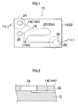
- FIG. 1 is a plan view to explain the construction of an educational tool for scientific experiments 10 that is an evaluation apparatus for scientific phenomena according to the invention.
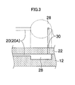
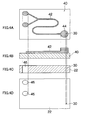
- Figs. 2 and 3 are a partially enlarged section and the like of Fig. 1, Fig. 2 shows a first liquid reservoir 24 (within the dotted line up left in Fig. 1), and Fig. 3 shows a third liquid reservoir 28 (within the dotted line down right in Fig. 1).
- the educational tool for scientific experiments 10 is constituted by a base plate 12 on a plate-like surface of which there are formed long grooves (14, 16 and 20), each having a cross-sectional area of not more than 1 mm 2 , a cover plate 22 that is disposed on the surface of the base plate 12 in close contact therewith and forms fine flow passages (14A, 16A and 20A) on the base plate 12 by covering the long grooves.
- the fine flow passages that are formed by the long grooves (14, 16 and 20) are constituted by a first flow passage 14A and a second flow passage 16A having almost the same length, which join in at a meeting point 18, and a third flow passage 20A that joints the first flow passage 14A and the second flow passage 16A at the meeting point 18.
- the other end of the first flow passage 14A is in communication with a first liquid reservoir 24, which is a cylindrical hollow part formed on the cover plate 22, the other end of the second flow passage 16A is in communication with a second liquid reservoir 26, which is a cylindrical hollow part formed on the cover plate 22, and the other end of the third flow passage 20A is in communication with a third liquid reservoir 28, which is a cylindrical hollow part formed on the base plate 12.
- a through hole 30 that permits communication between the third liquid reservoir 28 and outside air.
- the volume of the first liquid reservoir 24, the second reservoir 26 and the third reservoir 28 be 5 to 5000 mm 3 .
- the two-dimensional size of the base plate 12 and cover plate 22 is not especially limited, from the nature of the educational tool 10 for scientific experiments that is used at school, it is possible to use portable sizes, for example, 80 x 50 mm. Also, the thickness of the base plate 12 and cover plate 22 is not especially limited. However, from the standpoint of strength, cost efficiency, etc., it is possible to adopt 5 mm or so, for example, for both.
- Materials for the base plate 12 are not especially limited. However, from the standpoint of facilitating the manufacturing methods that will be described later, resins, more concretely, polydimethylsulfoxide (PDMS), polymethyl methacrylate (PMMA), polyvinyl chloride (PVC), ultraviolet curing resin, polycarbonate (PC), etc. can be advantageously used.
- PDMS polydimethylsulfoxide
- PMMA polymethyl methacrylate
- PVC polyvinyl chloride
- UV curing resin polycarbonate
- PC polycarbonate
- the cross-sectional area of the long grooves (14, 16 and 20) formed on the surface of the base plate 12 is not more than 1 mm 2 as stated earlier, more preferably 0.0025 to 0.64 mm 2 and most preferably 0.01 to 0.25 mm 2 .
- the cross-sectional shape of the long grooves (14, 16 and 20) is not especially limited and various shapes such as rectangle (square, oblong), trapezoid, V-shape and semicircle can be adopted. However, from the standpoint of facilitating the manufacturing methods that will be described later, the rectangle (square, oblong) is preferable.
- Materials for the cover plate 22 are not especially limited. However, transparent materials are preferable to ensure that the scientific phenomena in the flow passages can be recognized by the visual sense. As such materials, it is possible to adopt various kinds of resin plates, more concretely, polydimethylsulfoxide (PDMS), polymethyl methacrylate (PMMA), polyvinyl chloride (PVC), ultraviolet curing resin, polycarbonate (PC), etc., various kinds of resin films, more concretely, polyethylene terephthalate (PET), polyethylene naphthalate (PEN), triacethyl cellulose (TAC), etc., and various kinds of glasses (soda-lime glass, borosilicate glass, etc.).
- PDMS polydimethylsulfoxide
- PMMA polymethyl methacrylate
- PVC polyvinyl chloride
- UV curing resin polycarbonate
- PC polycarbonate
- various kinds of resin films more concretely, polyethylene terephthalate (PET), polyethylene naphthalate (PEN), triace
- this cover plate 22 is formed from a flat plate the front and rear surfaces of which are flat.
- the front surface that corresponds to the fine flow passages (14A, 16A and 20A) in a convex shape so as to permit observation in an enlarged condition.
- the front surface (the surface on which the long grooves are formed) of the base plate 12 and the rear surface (the surface that comes into close contact with the base plate 12) of the cover plate 22 sufficient flatness be ensured for the formation of the flow passages (14A, 16A and 20A) and from the standpoint of prevention of liquid leakage etc.
- the base plate 12 As preferred methods of forming the base plate 12, there are available a method that involves using a reverse template 40 to form the base plate 12 and a method that involves using any one of the micromachining processes of machine-working by use of a machining center and the like, electrical discharge machining, ultrasonic machining, photoetching and microdrilling.
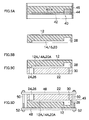
- Figs. 4A to 4D and Figs. 5A to 5D show the method in which the reverse template 40 is used.
- Fig. 4A is a top view of the reverse template 40
- Fig. 4B is a side view of the reverse template 40
- Fig. 4C is a side sectional view of the cover plate 22
- Fig. 4D is a top view of the cover plate 22.
- a description will be made of a case where the first and second liquid reservoirs 24, 26 are formed on the cover plate 22 and the through hole 30 is omitted and, at the same time, the third liquid reservoir 28 is formed on the substrate 12 and the through hole 30 of the third reservoir 28 is formed in the cover plate 22.
- the reverse template 40 on the surface of which the reverse shapes of the long grooves (14, 16 and 20) of the base plate 12 are formed is prepared. It is necessary that on the surface of this reverse template, the revere shape of the third liquid reservoir 28 be further formed beforehand. That is, on the surface of this reverse template 40 there are formed a convex flow passage pattern 42 that becomes the long grooves (14, 16 and 20) when reversed and a third liquid reservoir pattern 44.
- this reverse template 40 it is possible to adopt various kinds of publicly known micromachining processes, such as machine-working by use of a machining center and the like, electrical discharge machining, ultrasonic machining, photoetching and microdrilling.
- two pattern forms 46, 46 that become the first liquid reservoir 24 and the second liquid reservoir 26 are drilled and, at the same time, the through hole 30 of the third liquid reservoir is drilled.
- a release agent is applied to the surface of this reverse template 40.
- An appropriate release agent can be adopted according to the kind of a resin material that becomes the base plate 12, working conditions (temperature etc.) and the like.
- a resin material is flown onto and applied to the surface (on the side where the convex flow passage pattern 42 and the third liquid reservoir pattern 44 are formed) of the reverse template 40 and this resin material is caused to cure.
- the resin material is, for example, an ultraviolet curing resin
- the resin material after application is caused to cure by irradiation with ultraviolet rays.
- the resin material is, for example, a thermosetting resin such as polyvinyl chloride (PVC)
- PVC polyvinyl chloride
- the resin material after curing is stripped from the reverse template 40.
- the base plate 12 on which the long grooves (14, 16 and 20) and the third liquid reservoir 28 are formed is fabricated.
- the formed base plate 12 and the cover plate 22 of Fig. 4D which has been prepared beforehand, are fitted against each other as shown in Fig. 5.
- the mating surfaces may be bonded together with an adhesive or the like.
- a casing 49 is mounted to the base plate 12 and the cover plate 22. That is, a pair of transparent holder plates 48, 48 is applied to both sides of the base plate 12 and the cover plate 22 that are fitted against each other, and the holder plates 48 are connected together by being sandwiched by use of connecting devices that are multiple bolts 50, 50 ... and nuts 52, 52 ⁇ .
- the holder plates be evenly sandwiched in places of at least four corners by use of the bolts 50 and the nuts 52.
- the above-described method of manufacturing the educational tool for scientific experiments 10 in which the reverse template 40 is used is especially suitable for a case where a soft resin is used as the resin material.
- a soft resin is used as the resin material.
- PDMS polydimethylsulfoxide
- the above-described method of manufacturing the educational tool for scientific experiments 10 in which a micromachining process is used is especially suitable for a case where a hard resin is used as the resin material.
- a hard resin In the case of a hard resin, however, the adhesion between the base plate 12 and the cover plate 22 tends to worsen and by mounting the casing 49, liquid leakage from between the base plate 12 and the cover plate 22 can be positively prevented.
- PMMA polymethyl methacrylate
- the casing 49 is especially effective in improving the adhesion.
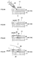
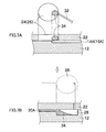
- Figs. 6A to 6D and Figs. 7A and 7B are sectional views to explain the procedure for an experiment method.
- Figs. 6A to 6D show a time-series procedure in the first liquid reservoir 24 and the second liquid reservoir 26.
- Fig. 7A shows the condition of the start of an experiment in which a sample liquid is supplied to in the first liquid reservoir 24 and the second liquid reservoir 26
- Fig. 7B shows the state of the finish of the experiment in which the sample liquid has reached the third liquid reservoir 28.
- a prescribed amount of sample liquid 34 is supplied to the first liquid reservoir 24 (or the second liquid reservoir 26) by use of a dropper for sample liquid 32. As shown in Fig. 6(B) and Fig. 7(A), this sample liquid 34 is supplied so as to block a portion that is in communication with the flow passage 14A (or 16A) in the first liquid reservoir 24 (or the second liquid reservoir 26).
- the first liquid reservoir 24 (or the second liquid reservoir 26) is covered with a tape 36 for sealing the sample liquid inlet and outlet.
- a tape 36 for sealing the sample liquid inlet and outlet.
- one surface (the bottom surface in the figure) thereof is coated with an adhesive and as a result of this, the first liquid reservoir 24 (or the second liquid reservoir 26) is shut off from outside air.
- a finger tip 38 is brought into contact with the tape 36.
- a liquid delivering device is formed in the first liquid reservoir 24 (or the second liquid reservoir 26).
- this liquid delivering device is based on the principle that due to the heat from the finger tip 38, cubical expansion occurs in the gas in the first liquid reservoir 24 (or the second liquid reservoir 26), with the result that the sample liquid 34 is fed into the flow passage 14A (or 16A).
- this liquid delivering device may be based on the principle that by depressing the tape 36 with the finger tip 38, thereby to reduce the volume of the first liquid reservoir 24 (or the second liquid reservoir 26), the sample liquid 34 is fed into the flow passage 14A (or 16A).
- the sample liquid 34 reaches the third liquid reservoir 28 by use of the above-described liquid delivering device and the experiment is finished.
- the sample liquids 34 by delivering sample liquids 34 into the flow passage 14A and the flow passage 16A at the same time from the first liquid reservoir 24 and the second liquid reservoir 26 each by use of a liquid delivering device, it is possible to observe how the sample liquids 34 joins in at the meeting point 18.
- this educational tool for scientific experiments can also be applied as various educational tools for scientific experiments other than this.
- first liquid reservoir 24 and the second liquid reservoir 26 are formed on the cover plate 22 and the third liquid reservoir 28 is formed on the base plate 12.
- all liquid reservoirs can be formed on the cover plate 22.
- the dropper for sample liquid 32 is used to supply a sample liquid (reagent) to the liquid reservoirs (24, 26, etc.), in place of this it is also possible to use an injector, a microsyringe, etc. having the same function. In general, it is desirable to use an inexpensive dropper as an educational tool for scientific experiments. However, according to the purpose of a test, it may sometimes be desirable to use the above-described injector, microsyringe, etc. having the same function.
Landscapes
- Engineering & Computer Science (AREA)
- General Physics & Mathematics (AREA)
- Physics & Mathematics (AREA)
- Theoretical Computer Science (AREA)
- Mathematical Analysis (AREA)
- Mathematical Optimization (AREA)
- Business, Economics & Management (AREA)
- Mathematical Physics (AREA)
- Algebra (AREA)
- Computational Mathematics (AREA)
- Educational Administration (AREA)
- Educational Technology (AREA)
- Pure & Applied Mathematics (AREA)
- Instructional Devices (AREA)
Abstract
Description
(Used as a pattern form when resin is poured during the formation of the
(Used to supply a necessary sample liquid (reagent) to the first
(Provides covers for the first
(Used to make a hole in the tape as required when a sample liquid is supplied or recovered, in order to put air into the first
(This casing is mounted when this experiment set is assembled, in order to prevent liquid leakage from between the
(When heat is applied to the first
(Necessary chemical agents that suit the purpose are supplied in reagent containers as test reagents for performing this scientific experiment. As sample liquids, for example, coloring liquids represented by coloring matter or pigments, and transparent liquids such as water can be mentioned.)
(A guide that describes the purpose of experiments conducted by use of this set, descriptions of phenomena, applications and uses, and phenomena that can be learned with this set is attached as required.)
Incidentally, although in this set the
Claims (14)
- An evaluation apparatus (10) of scientific phenomena, characterized by comprising:a base plate (12) of a plate-like body whose surface is formed a long groove (14, 16, 20) having a transversely cross-sectional area of not more than 1 mm2; anda cover plate (22) that is disposed on a surface of the base plate (12) in close contact therewith and forms a fine flow passage on the base plate (12) by covering the long groove (14, 16, 20), wherein scientific phenomena in the flow passage can be visually recognized.
- An evaluation apparatus (10) of scientific phenomena, characterized by comprising:a base plate (12) of a plate-like body whose surface is formed a long groove (14, 16, 20) having a transversely cross-sectional area of not more than 1 mm2; anda cover plate (22) that is disposed on a surface of the base plate (12) in close contact therewith and forms a fine flow passage on the base plate (12) by covering the long groove (14, 16, 20); anda casing (49) that supports the base plate (12) and the cover plate (22) by sandwiching the base plate (12) and the cover plate (22) that are fitted against each other from both sides of the plates (12, 22), wherein scientific phenomena in the flow passage can be visually recognized.
- The evaluation apparatus (10) of scientific phenomena according to claim 1 or 2, wherein the base plate (12) and/or the cover plate (22) is transparent.
- The evaluation apparatus (10) of scientific phenomena according to claim 1 or 2, wherein the base plate (12) and/or the cover plate (22) is formed from a resin material.
- The evaluation apparatus (10) of scientific phenomena according to any one of claims 2 to 4, wherein the casing (49) is constituted by a pair of transparent holder plates (48) to be applied to both sides of the base plate (12) and the cover plate (22) that are fitted against each other and a connecting device (50, 52) that connects the holder plates (48) so as to sandwich the base plate (12) and the cover plate (22).
- The evaluation apparatus (10) of scientific phenomena according to any one of claims 1 to 4, wherein an end of each of the multiple flow passages joins in at one meeting place (18) and the other end of each of the multiple flow passages is in communication with a liquid reservoir (24, 26, 28) each having a volume of 5 to 5000 mm3.
- The evaluation apparatus (10) of scientific phenomena according to claim 1 or 2, wherein an end of a first flow passage and an end of a second flow passage meet each other at one meeting point (18), the two flow passages being the above-described flow passages having almost the same length,
wherein the other end of the first flow passage is in communication with a first liquid reservoir (24) having a volume of 5 to 5000 mm3,
wherein the other end of the second flow passage is in communication with a second liquid reservoir (26) having a volume of 5 to 5000 mm3, and
wherein an end of a third flow passage, which is one flow passage as described above, is in communication with the meeting point (18), the other end of the third flow passage being in communication with a third reservoir (28) having a volume of 5 to 5000 mm3. - The evaluation apparatus (10) of scientific phenomena according to claim 7, wherein in the cover plate (22) there is formed a through hole (30) that permits communication of outside air with at least one of the first reservoir (24), the second reservoir (26) and the third reservoir (28).
- An educational tool for scientific experiments in which the evaluation apparatus (10) of scientific phenomena according to any one of claims 1 to 4 is a portable experiment apparatus.
- A method of manufacturing the evaluation apparatus of scientific phenomena according to any one of claims 1 to 4, comprising the steps of:applying a resin material to a surface of a reverse template on the surface of which a reverse shape of the long groove of the base plate (12) is formed;causing the resin material to cure; andstripping the resin material after curing from the reverse template thereby to form the base plate (12).
- A method of manufacturing the evaluation apparatus of scientific phenomena according to any one of claims 1 to 4, comprising:the base plate forming step that involves, by use of a reverse template (40) on the surface of which a reverse shape of the long groove to be formed on the base plate (12) is formed, applying a resin material to a surface of the reverse template (40), causing the resin material to cure, and stripping the resin material after curing from the reverse template (40) thereby to form the base plate (12);the fitting step that involves fitting the cover plate (22) against the surface of the base plate (12) to cover the long groove, whereby the fine flow passage is formed on the base plate (12); andthe casing mounting step that involves mounting a casing (49) to the base plate (12) and the cover plate (22) that are fitted against each other and supporting the base plate (12) and the cover plate (22) so as to sandwich the plates (12, 22), whereby the base plate (12) and the cover plate (22) are brought into close contact with each other.
- A method of manufacturing the evaluation apparatus of scientific phenomena according to any one of claims 1 to 4, comprising:the base plate forming step that involves forming the long groove on the surface of the base plate (12) by any of the micromachining processes of machine-working by use of a machining center and the like, electrical discharge machining, ultrasonic machining, photoetching and microdrilling;the fitting step that involves fitting the cover plate (22) against the surface of the base plate (12) to cover the long groove, whereby the fine flow passage is formed on the base plate (12); andthe casing mounting step that involves mounting a casing (49) to the base plate (12) and the cover plate (22) that are fitted against each other and supporting the base plate (12) and the cover plate (22) so as to sandwich the plates (12, 22), whereby the base plate (12) and the cover plate (22) are brought into close contact with each other.
- A method of manufacturing the evaluation apparatus of scientific phenomena according to any one of claims 1 to 4, comprising:the base plate forming step that involves, by use of a reverse template (40) on the surface of which a reverse shape of the long groove to be formed on the base plate (12) is formed, applying a resin material to a surface of the reverse template (40), causing the resin material to cure, and stripping the resin material after curing from the reverse template (40) thereby to form the base plate (12);the fitting step that involves fitting the cover plate (22) against the surface of the base plate (12) to cover the long groove, whereby the fine flow passage is formed on the base plate (12); andthe casing mounting step that involves applying a pair of transparent holder plates (48) to both sides of the base plate (12) and the cover plate (22) that are fitted against each other and connecting the holder plates (48) together by use of a connecting device (50, 52) so as to be sandwiched, whereby the base plate (12) and the cover plate (22) are brought into close contact with each other.
- A method of manufacturing the evaluation apparatus of scientific phenomena according to any one of claims 1 to 4, comprising:the base plate forming step that involves the long groove is formed on the surface of the base plate (12) by any of the micromachining processes of machine-working by use of a machining center and the like, electrical discharge machining, ultrasonic machining, photoetching and microdrilling;the fitting step that involves fitting the cover plate (22) against the surface of the base plate (12) to cover the long groove, whereby the fine flow passage is formed on the base plate (12); andthe casing mounting step that involves applying a pair of transparent holder plates (48) to both sides of the base plate (12) and the cover plate (22) that are fitted against each other and connecting the holder plates (48) together by use of a connecting device (50, 52) so as to be sandwiched, whereby the base plate (12) and the cover plate (22) are brought into close contact with each other.
Applications Claiming Priority (4)
| Application Number | Priority Date | Filing Date | Title |
|---|---|---|---|
| JP2004045314 | 2004-02-20 | ||
| JP2004045314A JP4392554B2 (en) | 2004-02-20 | 2004-02-20 | Scientific phenomenon evaluation device, science experiment teaching material, and manufacturing method thereof |
| JP2004045319 | 2004-02-20 | ||
| JP2004045319A JP2005234390A (en) | 2004-02-20 | 2004-02-20 | Evaluation apparatus for scientific phenomenon and teaching material for science experiment, and method for manufacturing same |
Publications (1)
| Publication Number | Publication Date |
|---|---|
| EP1566784A1 true EP1566784A1 (en) | 2005-08-24 |
Family
ID=34713013
Family Applications (1)
| Application Number | Title | Priority Date | Filing Date |
|---|---|---|---|
| EP05003528A Withdrawn EP1566784A1 (en) | 2004-02-20 | 2005-02-18 | Evaluation apparatus of scientific phenomena, educational tool for scientific experiments and method of manufacturing the same |
Country Status (2)
| Country | Link |
|---|---|
| US (1) | US7316569B2 (en) |
| EP (1) | EP1566784A1 (en) |
Cited By (1)
| Publication number | Priority date | Publication date | Assignee | Title |
|---|---|---|---|---|
| EP1603100A1 (en) * | 2004-06-01 | 2005-12-07 | Fuji Photo Film Co., Ltd. | Scientific phenomena evaluation device and manufacturing method of the same |
Families Citing this family (2)
| Publication number | Priority date | Publication date | Assignee | Title |
|---|---|---|---|---|
| JP2005234389A (en) * | 2004-02-20 | 2005-09-02 | Fuji Photo Film Co Ltd | Evaluation apparatus for scientific phenomenon and teaching material for science experiment, and method for manufacturing same |
| JP2005345610A (en) * | 2004-06-01 | 2005-12-15 | Fuji Photo Film Co Ltd | Scientific phenomenon evaluating device and scientific phenomenon evaluating method using the device |
Citations (5)
| Publication number | Priority date | Publication date | Assignee | Title |
|---|---|---|---|---|
| US4034493A (en) * | 1975-10-29 | 1977-07-12 | Wham-O Mfg. Co. | Fluid novelty device |
| US5242307A (en) * | 1992-07-13 | 1993-09-07 | Reinbold Paul J | Teaching tank |
| DE20005052U1 (en) * | 2000-03-20 | 2000-07-20 | Höller, Stefan, 23552 Lübeck | Device for displaying chemical and / or physical tests |
| JP2000242162A (en) * | 1999-02-19 | 2000-09-08 | Toyo Eng Works Ltd | Observation device for natural phenomena due to changes in water temperature |
| US6254396B1 (en) * | 1999-09-28 | 2001-07-03 | Delta Education, Inc. | Teaching device for science experiments |
Family Cites Families (8)
| Publication number | Priority date | Publication date | Assignee | Title |
|---|---|---|---|---|
| US1939776A (en) * | 1932-11-05 | 1933-12-19 | Frederic E Holmes | Apparatus for producing activity or work by atmospheric conditions and displaying the same |
| US1947605A (en) * | 1932-12-30 | 1934-02-20 | Robert J Linney | Demonstration apparatus |
| US2848822A (en) * | 1955-09-26 | 1958-08-26 | Charles L Morse | Educational toy for demonstrating the operation of the siphon |
| US3382593A (en) * | 1966-08-08 | 1968-05-14 | Larry D. Couch | Hydraulic demonstrator for oil filtering action |
| US3564733A (en) * | 1969-05-05 | 1971-02-23 | Flume Stabilization Syst | Educational device |
| NO142640C (en) * | 1978-08-23 | 1980-09-17 | Saga Petroleum | APPLICATION FOR USE FOR TRAINING FOR SIMULATION OF SITUATIONS THAT MAY BE INCURRED BY OIL AND GAS DRILLING |
| US4472145A (en) * | 1982-12-16 | 1984-09-18 | Freeman, Cooper & Company | Apparatus for teaching electrochemical principles |
| US20060166177A1 (en) * | 2003-07-30 | 2006-07-27 | Hageman James H | Method of incorporating an active learning experience into a classroom |
-
2005
- 2005-02-18 EP EP05003528A patent/EP1566784A1/en not_active Withdrawn
- 2005-02-22 US US11/061,744 patent/US7316569B2/en not_active Expired - Fee Related
Patent Citations (5)
| Publication number | Priority date | Publication date | Assignee | Title |
|---|---|---|---|---|
| US4034493A (en) * | 1975-10-29 | 1977-07-12 | Wham-O Mfg. Co. | Fluid novelty device |
| US5242307A (en) * | 1992-07-13 | 1993-09-07 | Reinbold Paul J | Teaching tank |
| JP2000242162A (en) * | 1999-02-19 | 2000-09-08 | Toyo Eng Works Ltd | Observation device for natural phenomena due to changes in water temperature |
| US6254396B1 (en) * | 1999-09-28 | 2001-07-03 | Delta Education, Inc. | Teaching device for science experiments |
| DE20005052U1 (en) * | 2000-03-20 | 2000-07-20 | Höller, Stefan, 23552 Lübeck | Device for displaying chemical and / or physical tests |
Non-Patent Citations (1)
| Title |
|---|
| PATENT ABSTRACTS OF JAPAN vol. 2000, no. 12 3 January 2001 (2001-01-03) * |
Cited By (1)
| Publication number | Priority date | Publication date | Assignee | Title |
|---|---|---|---|---|
| EP1603100A1 (en) * | 2004-06-01 | 2005-12-07 | Fuji Photo Film Co., Ltd. | Scientific phenomena evaluation device and manufacturing method of the same |
Also Published As
| Publication number | Publication date |
|---|---|
| US7316569B2 (en) | 2008-01-08 |
| US20050186546A1 (en) | 2005-08-25 |
Similar Documents
| Publication | Publication Date | Title |
|---|---|---|
| Thomas et al. | Print-and-peel fabrication for microfluidics: what’s in it for biomedical applications? | |
| JP2003156502A (en) | Assembly microchip using breadboard for fluid microchip | |
| US20180078936A1 (en) | Systems, Devices, and Methods for Microfluidics Using Modular Blocks | |
| US7344378B2 (en) | Scientific phenomena evaluation device, educational tool for scientific experiments and manufacturing method of the device and tool | |
| Giri | Laboratory methods in microfluidics | |
| US7316569B2 (en) | Evaluation apparatus of scientific phenomena, educational tool for scientific experiments and method of manufacturing the same | |
| US7353693B2 (en) | Evaluation apparatus for scientific phenomena and evaluation method for scientific phenomena using the same | |
| US20050214721A1 (en) | Scientific phenomena evaluation apparatus, educational tool for scientific experiments and manufacturing method of the device and tool | |
| JP4081721B2 (en) | Scientific phenomenon evaluation apparatus and manufacturing method thereof | |
| JP4392554B2 (en) | Scientific phenomenon evaluation device, science experiment teaching material, and manufacturing method thereof | |
| EP1610282A1 (en) | Method for experiment using scientific phenomenon evaluation apparatus, and scientific phenomenon evaluation apparatus | |
| CN106563516B (en) | A kind of teaching preparation method of microchip | |
| JP2005234390A (en) | Evaluation apparatus for scientific phenomenon and teaching material for science experiment, and method for manufacturing same | |
| KR101053772B1 (en) | Molding module for manufacturing a microfluidic chip mold, a method for manufacturing a microfluidic chip mold using the same, and a microfluidic chip mold manufactured thereby | |
| EP1862990A1 (en) | Method of experiment with apparatus for evaluating scientific phenomenon and apparatus for evaluating scientific phenomenon | |
| EP1603099A1 (en) | Scientific phenomena evaluation device and scientific phenomena evaluation method using the device | |
| JP4482929B2 (en) | Manufacturing method of scientific phenomenon evaluation device | |
| CN206441437U (en) | A kind of microchip imparted knowledge to students for TLC | |
| Kant et al. | Engaging nanotechnology: ethnography of lab-on-a-chip technology in small-scale fluidics research | |
| JP2007268486A (en) | Microdevice fluid control method and mechanism, and scientific phenomenon evaluation apparatus using the same | |
| CN108597335A (en) | A kind of preparation method of green multifunctional teaching microchip | |
| JP2007093949A (en) | Drawing device | |
| Rogers et al. | Embossed Foil Microfluidics for the Classroom | |
| Azam et al. | Low-Cost 3D-Printed Microfluidic Devices for Rapid Prototyping and Biological Applications | |
| JP2006018224A (en) | Method for experiment using scientific phenomenon evaluation apparatus, and scientific phenomenon evaluation apparatus |
Legal Events
| Date | Code | Title | Description |
|---|---|---|---|
| PUAI | Public reference made under article 153(3) epc to a published international application that has entered the european phase |
Free format text: ORIGINAL CODE: 0009012 |
|
| AK | Designated contracting states |
Kind code of ref document: A1 Designated state(s): AT BE BG CH CY CZ DE DK EE ES FI FR GB GR HU IE IS IT LI LT LU MC NL PL PT RO SE SI SK TR |
|
| AX | Request for extension of the european patent |
Extension state: AL BA HR LV MK YU |
|
| 17P | Request for examination filed |
Effective date: 20051104 |
|
| AKX | Designation fees paid |
Designated state(s): DE GB |
|
| RBV | Designated contracting states (corrected) |
Designated state(s): AT BE BG CH CY CZ DE DK EE ES FI FR GB GR HU IE IS IT LI LT LU MC NL PL PT RO SE SI SK TR |
|
| RAP1 | Party data changed (applicant data changed or rights of an application transferred) |
Owner name: FUJIFILM CORPORATION |
|
| 17Q | First examination report despatched |
Effective date: 20121130 |
|
| STAA | Information on the status of an ep patent application or granted ep patent |
Free format text: STATUS: THE APPLICATION IS DEEMED TO BE WITHDRAWN |
|
| 18D | Application deemed to be withdrawn |
Effective date: 20130411 |