EP1566708B1 - Winding device - Google Patents
Winding device Download PDFInfo
- Publication number
- EP1566708B1 EP1566708B1 EP20040405781 EP04405781A EP1566708B1 EP 1566708 B1 EP1566708 B1 EP 1566708B1 EP 20040405781 EP20040405781 EP 20040405781 EP 04405781 A EP04405781 A EP 04405781A EP 1566708 B1 EP1566708 B1 EP 1566708B1
- Authority
- EP
- European Patent Office
- Prior art keywords
- disc
- ring
- organ
- winding
- recesses
- Prior art date
- Legal status (The legal status is an assumption and is not a legal conclusion. Google has not performed a legal analysis and makes no representation as to the accuracy of the status listed.)
- Active
Links
Images


Classifications
-
- G—PHYSICS
- G04—HOROLOGY
- G04B—MECHANICALLY-DRIVEN CLOCKS OR WATCHES; MECHANICAL PARTS OF CLOCKS OR WATCHES IN GENERAL; TIME PIECES USING THE POSITION OF THE SUN, MOON OR STARS
- G04B3/00—Normal winding of clockworks by hand or mechanically; Winding up several mainsprings or driving weights simultaneously
- G04B3/06—Keys or the like with means preventing overwinding
Definitions
- the present invention relates to the field of mechanical watchmaking. It relates, more particularly, a winding device comprising a crown of the type mounted at the end of a winding stem.
- the rod ensures, in particular, the armature function of the motor spring of a mechanical watch with manual winding. In its middle part, it is kinematically connected to a winding pinion which, via a gear train, drives the mainspring. At its outer end, the rod is fixed, often by screwing, to the winding crown.
- the U.S. Patent 2,571,879 discloses a mechanism comprising a spring and balls, arranged to produce a disengagement and generate a warning rattling when the carrier raises the spring excessively. This solution allows, admittedly, to limit the arming of the spring, but it does not guarantee, in the long run, satisfactory operating conditions, because of a significant risk of clogging of the mechanism.
- the document FR 1 230 864 proposes to insert between the crown and the spring, a coupling member with limited torque having a very low friction, housed inside the movement.
- This friction can be modulated by means of a spring whose tension can be adjusted by means of a nut.
- Such a solution occupies a volume considerable inside the movement and requires delicate adjustments, which may be out of order.
- the main object of the present invention is to provide a winding device that is particularly simple and easy to produce and that makes it possible to avoid any over-winding of the mainspring without taking up space inside the movement. Furthermore, the device according to the invention also aims to withstand wear and damage caused by time and conditions of use.
- the elastic member has an axial deformation when the torque is applied.
- the connecting means comprise recesses on the faces of the part and the clutch plate facing one another and balls positioned in the recesses.
- the engagement of the balls in the shallower recesses, disk or part, defines the arming of the elastic member.
- the connecting means are formed of bosses and recesses, formed on the clutch part and the others on the clutch disc, these bosses being arranged to engage in the hollows.
- the elastic member consists of a coil spring interposed between the ring and the clutch disc. This solution occupies little space and allows a good control of the limit torque.
- the elastic member In order to reduce the volume occupied by the elastic member, it consists of a sinus circle inserted between the ring and the clutch disc.
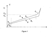
- the figure 1 shows the typical winding A and disarming curves B of a mainspring, with the number of windings on the abscissa and the pair on the y-axis. If one starts from the point 0, we see that, in a first zone A has the couple growing rapidly, the slope tapering. In this area, the barrel spring begins to wind on its shaft. In the area A b , the torque increases substantially linearly. The barrel spring flexes and coils progressively on the shaft, until the armature reaches a limit value C lim . If the arming continues, the torque then increases again strongly, as can be seen in the area A c , the spring being subjected to traction. If the applied torque exceeds a limit value C r , the spring may break.
- the torque applied by the mainspring on the wheel of the watch is slightly lower than the armature torque, because of friction losses.
- the decay of the torque is substantially linear, whereas in the zone B a , it decreases in a quadratic way, to find the point 0.
- the disarming curve does not have an area equivalent to the zone A c , it is because the arming of the spring is guaranteed by a pawl which has a sufficient back to find the linear zone.
- the torque must be brought to a value C max as close as possible to C lim, but in all cases, less than C r .
- the torque C max must be defined with an accuracy of 10 to 20%
- FIGS. 2a and 2b represent a first variant of a winding device 10 to torque limitation according to the invention, respectively seen in axial section and in plan. It is intended to equip a watch provided with a box provided with a tube 12, visible only on the figure 2a with whom he cooperates. This tube 12 is intended to provide a connection between the inside and outside of the box, in particular to perform the reassembly and time setting operations.
- the clutch part 20 must bear against the bottom 14a of the ring 14 and be able to rotate freely.
- the ring 14 and the part 20 are not permanently integral in rotation.
- the clutch disc 22 is disposed in the ring 14 so that it is integral in rotation, for example by defining an octagonal periphery of the disc 22, of complementary shape to that which the housing 15 presents in its part between litters 14d and 14e. It must, in addition, be able to move axially, so as to allow a disengagement between the part 20 and the disk 22, as will be explained later.
- the assembly of the device as defined is carried out by placing in the housing 15 the plate 20a of the clutch part 20, its sleeve 20a being turned outward. It will be noted that the edge of the plate 20a is disengaged in its portion adjoining the bottom 14a, so that contact between the part 20 and the ring 14 is only in the central part, to reduce friction .
- the balls 24 are put in place, one in each of the recesses 20d.
- the disk 22 is then engaged on the part 20, the central opening 22a surrounding the sleeve 20a.
- the recesses 22b are arranged so that the balls 24 engage, the disc 22 is thus positioned radially and axially with reference to the part 20, and can roll on it, but without direct contact.
- the ring 26 is prepared, by driving the ring 32 so that it defines a space in which the seal 30 can take place. After introducing the spring 28 into the groove 26a, the ring thus mounted and driven into the housing 15 of the crown 14, to abut against the scope 14d.
- the contact between the ring 26 and the wall of the crown 14 must be perfect, so that no liquid can penetrate. To ensure this contact, it is possible to fix these parts to each other by driving and gluing.
- the seal 30 can be put in place on the ring 14, either before or after the mounting of the ring 26. It can, in addition, be easily replaced during the after-sales service.
- the rod 18 can then be screwed onto the sleeve 20b.
- it advantageously comprises two plates parallel to each other and oriented longitudinally, which allow to tighten the sleeve 20b and thus ensure a screwing bottom of the rod 18 in the threaded hole.
- the device 10 is then mounted in a watch movement, the rod 18 being engaged in the box by the tube 12 and cooperating with a winding pinion which provides the winding of a mainspring, in a conventional manner, with a simple rotation of the ring 14.
- the tube 12 and the seal 30 are dimensioned so that they are in close contact with each other. the other. In this way, the housing 15 forms a confined space which is open only towards the inside of the box.
- the rotational movement of the ring gear 14 is transmitted to the rod 18 by the disengaging member 16.
- the spring 28 is armed (ie compressed) and the balls 24 out of the recesses 20d, which are shallower than the recesses 22b, and roll in the raceway to move to the next recess. In this way, the disk 22 is disengaged from the part 20 and the winding of the mainspring can no longer be done.
- the torque C max is essentially defined by the characteristics of the spring 28 and by the distance between the bottom of the groove 26a and the bearing surface of the clutch disk 22. However, to ensure this distance, it is necessary that the ring 26 is perfectly positioned with reference to the disk 22, which can be achieved by defining tight tolerances between the bearing surface of the part 20 in the bottom of the cap 14 and the bearing 14d.
- This torque is also influenced by the friction of the various component parts of the device. This is why special attention must be given to the surface states of the parts in contact with each other. Because the space is confined, it is possible to lubricate the surfaces in relative motion, so as to ensure good working conditions.
- the user applies a traction force on the crown 14, which arms the spring 28.
- the ring 26 bears against the disc 22 on the opposite side to that comprising the recesses 22a. .
- the balls 24 are pressurized and transmit the force to the part 20 which axially drives the rod 18 which tends to exit the box to take a position in which it is possible to perform a time setting. This operation is done by a rotation of the crown 14. It is obvious that, to be able to perform it without problem, the couple to apply to train the gear and the mechanisms of the watch must be less than Cmax.
- the essential difference lies in the fact that the seal 30 is housed in a groove 12a that includes the tube 12. In this way, the structure of the ring 26 is simplified.
- the ring 26 has a radially oriented annular groove 26c in which is housed the seal 30 which is here formed of a single piece toric.
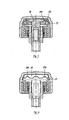
- Variants of Figures 5 and 6 do not have a ball.
- the clutch part 20 cooperates directly with the clutch disc 22, the latter being provided with spherical bosses 22c engaged in the recesses 20d of the clutch part 20 for the variant of the clutch.
- figure 5 whereas in the variant of the figure 6 they are bosses 22d with radial orientation and trapezoidal section which cooperate with the recesses 20d.
- the shape of the latter is, of course, adapted to that of the bosses 22d.
Description
La présente invention se rapporte au domaine de l'horlogerie mécanique. Elle concerne, plus particulièrement, un dispositif de remontoir comprenant une couronne du type montée à l'extrémité d'une tige de remontoir.The present invention relates to the field of mechanical watchmaking. It relates, more particularly, a winding device comprising a crown of the type mounted at the end of a winding stem.
La tige assure, notamment, la fonction d'armage du ressort-moteur d'une montre mécanique à remontage manuel. Dans sa partie médiane, elle est reliée cinématiquement à un pignon de remontoir qui, par l'intermédiaire d'un train d'engrenages, entraîne le ressort-moteur. A son extrémité extérieure, la tige est fixée, souvent par vissage, à la couronne de remontoir.The rod ensures, in particular, the armature function of the motor spring of a mechanical watch with manual winding. In its middle part, it is kinematically connected to a winding pinion which, via a gear train, drives the mainspring. At its outer end, the rod is fixed, often by screwing, to the winding crown.
L'un des problèmes qui peut survenir au cours de l'utilisation d'une montre munie d'un tel système, se manifeste à la fin de l'opération d'armage du ressort-moteur. En effet, il peut être très dommageable pour la montre si son porteur continue à faire pivoter la tige de remontoir alors que le ressort-moteur est déjà armé au maximum. Cela peut entraîner la rupture du ressort, de la tige ou abîmer une partie du train d'engrenages.One of the problems that can occur during the use of a watch provided with such a system, is manifested at the end of the winding operation of the mainspring. Indeed, it can be very damaging to the watch if the wearer continues to rotate the winding stem while the mainspring is already armed to the maximum. This can lead to breakage of the spring, rod or damage to a part of the gear train.
Pour éviter un surarmage du ressort-moteur, en agissant au niveau du système de remontage et particulièrement sur la couronne de remontoir, le
De manière plus intéressante, le document
La présente invention a pour but principal de fournir un dispositif de remontoir particulièrement simple et facile à produire et permettant d'éviter tout surarmage du ressort-moteur, sans occuper d'espace à l'intérieur du mouvement. Par ailleurs, le dispositif selon l'invention a également pour objectif de bien résister à l'usure et aux dommages causés par le temps et les conditions d'utilisation.The main object of the present invention is to provide a winding device that is particularly simple and easy to produce and that makes it possible to avoid any over-winding of the mainspring without taking up space inside the movement. Furthermore, the device according to the invention also aims to withstand wear and damage caused by time and conditions of use.
De façon plus précise, l'invention concerne un dispositif de remontoir à limitation de couple, destiné à armer jusqu'à une valeur limite, un ressort-moteur de mouvement de montre disposé à l'intérieur d'une boîte et comprenant :
- un tube (12) destiné à être solidaire de ladite boîte et définissant un axe (A-A),
- une couronne de remontoir (14) présentant une forme de coiffe avec un fond (14a) et une paroi cylindrique (14b), ladite couronne étant mobile en rotation autour dudit axe (A-A),
- un organe de débrayage (16), et
- une tige de remontoir (18), cinématiquement reliée ou non à la couronne de remontoir (14) par l'organe de débrayage (16) selon que le couple du ressort-moteur est inférieur ou supérieur à la valeur limite, et destinée à être engagée coaxialement dans ledit tube (12).
- a tube (12) intended to be integral with said box and defining an axis (AA),
- a crown crown (14) having a cap shape with a bottom (14a) and a cylindrical wall (14b), said ring being rotatable about said axis (AA),
- a disengaging member (16), and
- a winding stem (18), kinematically connected or not to the winding crown (14) by the clutch member (16) depending on whether the torque of the mainspring is less than or greater than the limit value, and intended to be coaxially engaged in said tube (12).
Selon l'invention, le dispositif comporte, en outre :
- une bague (26) fixée rigidement et de manière étanche à la face intérieure de ladite paroi cylindrique (14b)
- un organe d'étanchéité (30) intercalé entre ladite bague (26) et ledit tube (12), délimitant un espace confiné (15) à l'intérieur duquel est logé ledit organe de débrayage,
l'organe de débrayage (16) comportant :- une pièce d'embrayage (20) solidaire de ladite tige (18),
- un disque d'embrayage (22),
- des moyens de liaison du disque (22) et de la pièce d'embrayage (20), et
- un organe élastique (28, 38, 40) agencé pour solidariser ledit disque (22) et ladite pièce (20) par l'intermédiaire desdits moyens de liaison (24) tant que le couple appliqué est inférieur à ladite valeur limite.
- a ring (26) rigidly and sealingly attached to the inner face of said cylindrical wall (14b)
- a sealing member (30) interposed between said ring (26) and said tube (12), delimiting a confined space (15) inside which said disengaging member is housed,
the disengaging member (16) comprising:- a clutch part (20) integral with said rod (18),
- a clutch disc (22),
- means for connecting the disc (22) and the clutch part (20), and
- an elastic member (28, 38, 40) arranged for securing said disc (22) and said workpiece (20) via said connecting means (24) as long as the applied torque is less than said limit value.
L'organe élastique présente une déformation axiale lorsque le couple est appliqué.The elastic member has an axial deformation when the torque is applied.
Dans une première variante permettant de maîtriser avec précision le couple limite, les moyens de liaison comprennent des creusures sur les faces de la pièce et du disque d'embrayage situées en regard l'une de l'autre et des billes positionnées dans les creusures. L'engagement des billes dans les creusures les moins profondes, du disque ou de la pièce, définit l'armage de l'organe élastique.In a first variant making it possible to control the limit torque accurately, the connecting means comprise recesses on the faces of the part and the clutch plate facing one another and balls positioned in the recesses. The engagement of the balls in the shallower recesses, disk or part, defines the arming of the elastic member.
Dans une deuxième variante, plus économique, les moyens de liaison sont formés de bossages et de creusures, pratiqués les uns sur la pièce d'embrayage et les autres sur le disque d'embrayage, ces bossages étant agencés de manière à s'engager dans les creusures.In a second variant, more economical, the connecting means are formed of bosses and recesses, formed on the clutch part and the others on the clutch disc, these bosses being arranged to engage in the hollows.
L'organe élastique est constitué d'un ressort à boudin intercalé entre la bague et le disque d'embrayage. Cette solution occupe peu d'espace et permet une bonne maîtrise du couple limite.The elastic member consists of a coil spring interposed between the ring and the clutch disc. This solution occupies little space and allows a good control of the limit torque.
Afin de réduire le volume occupé par l'organe élastique, celui-ci est constitué d'un cercle sinus intercalé entre la bague et le disque d'embrayage.In order to reduce the volume occupied by the elastic member, it consists of a sinus circle inserted between the ring and the clutch disc.
Grâce au fait que la bague est fixée contre la paroi de la coiffe par collage, il est possible d'assurer une bonne étanchéité entre l'espace confiné et l'extérieur de la montre.Due to the fact that the ring is fixed against the wall of the cap by gluing, it is possible to ensure a good seal between the confined space and the outside of the watch.
Il est possible de simplifier la structure du dispositif en munissant le tube d'une gorge sur sa face extérieure, dans laquelle est monté le joint.It is possible to simplify the structure of the device by providing the tube with a groove on its outer face, in which is mounted the seal.
D'autres caractéristiques apparaîtront plus clairement à la lecture de la description qui suit, faite en regard du dessin annexé dans lequel :
- la
figure 1 illustre l'évolution de la tension du ressort-moteur au cours de son cycle d'armage et de désarmage, - les
figures 2a et 2b montrent, respectivement en plan et en coupe axiale, un premier mode de réalisation d'un dispositif selon l'invention, et - les
figures 3 à 5 sont des vues en coupe axiale d'autres modes de réalisation de l'invention.
- the
figure 1 illustrates the evolution of the tension of the mainspring during its winding and disarming cycle, - the
Figures 2a and 2b show, respectively in plan and in axial section, a first embodiment of a device according to the invention, and - the
Figures 3 to 5 are views in axial section of other embodiments of the invention.
La
Comme le montre la courbe B, le couple appliqué par le ressort de barillet sur le rouage de la montre est légèrement inférieur au couple d'armage, à cause des pertes par frottement. Dans la zone Bb, la décroissance du couple est sensiblement linéaire, alors que dans la zone Ba, elle décroît de manière quadratique, pour retrouver le point 0.As shown in curve B, the torque applied by the mainspring on the wheel of the watch is slightly lower than the armature torque, because of friction losses. In the zone B b , the decay of the torque is substantially linear, whereas in the zone B a , it decreases in a quadratic way, to find the point 0.
Si la courbe de désarmage ne présente pas de zone équivalente à la zone Ac, c'est parce que l'armage du ressort est garanti par un cliquet qui présente un recul suffisant pour retrouver la zone linéaire.If the disarming curve does not have an area equivalent to the zone A c , it is because the arming of the spring is guaranteed by a pawl which has a sufficient back to find the linear zone.
Pour garantir un armage optimum du ressort, il faut que son couple soit amené à une valeur Cmax aussi proche que possible de Clim mais, dans tous les cas, inférieure à Cr. La pratique montre que, pour obtenir ce résultat, il faut que le couple Cmax soit défini avec une précision de 10 à 20%To ensure optimum springing, the torque must be brought to a value C max as close as possible to C lim, but in all cases, less than C r . Practice shows that to obtain this result, the torque C max must be defined with an accuracy of 10 to 20%
Les
Le dispositif 10 comprend plus précisément :
- une couronne de remontoir 14 en forme de coiffe, munie d'un fond 14a et d'une
portion tubulaire 14b dont la paroi extérieure est munie de cannelures 14c et la paroi intérieure de portées14d et 14e, le fond 14a etla portion tubulaire 14b définissant un logement 15, - un organe de débrayage 16, monté dans le logement 15, et
- une tige de remontoir 18 fixée à l'organe de débrayage 16 et définissant un axe longitudinal AA.
- a winding
crown 14 in the form of a cap, provided with a bottom 14a and atubular portion 14b whose outer wall is provided with splines 14c and the inner wall ofspans 14d and 14e, the bottom 14a and thetubular portion 14b defining a housing 15, - a
release member 16, mounted in the housing 15, and - a winding
stem 18 fixed to therelease member 16 and defining a longitudinal axis AA.
L'organe de débrayage 16 comprend :
- une pièce d'embrayage 20 comportant un manchon 20a à orientation longitudinale, muni, à l'une de ses extrémités, d'un taraudage 20b dans lequel est fixée la tige 18 et, à l'autre, d'une assiette 20c s'étendant radialement, sa surface contiguë au manchon étant munie de huit creusures 20d réparties régulièrement sur un cercle C centré sur l'axe AA et reliées entre elles par un chemin de roulement, non visible au dessin,
l'assiette 20c étant disposée dans le logement 15, entre le fond 14a et la portée 14e de la couronne 14, et pouvant tourner librement dans la couronne 14, - un disque d'embrayage 22 muni d'une ouverture centrale 22a, dans laquelle est engagé le manchon 20a, et de huit creusures 22b disposées en regard des creusures 20d, et disposé dans le logement 15 entre les portées 14e et 14d, solidaire en rotation de la couronne 14, mais mobile en translation,
huit billes 24 intercalées entre la pièce 20 et le disque 22, positionnées dans les creusures20d et 22b,une bague 26 fixée rigidement à la face intérieure de la paroi cylindrique 14b et munie d'une gorge annulaire 26a, orientée axialement et ouverte dans le logement 15, et d'une portée 26b orientée radialement vers l'axe AA, et- un ressort à boudin 28 disposé dans la gorge 26a et en appui contre le disque 22 de manière à engendrer une force enserrant les billes 24 entre le disque 22
et l'assiette 20c.
- a
clutch part 20 comprising a longitudinally oriented sleeve 20a, provided at one of its ends with a tapping 20b in which is fixed therod 18 and, at the other, with aplate 20c extending radially, its surface contiguous to the sleeve being provided with eightrecesses 20d regularly distributed on a circle C centered on the axis AA and connected together by a raceway, not visible in the drawing, theplate 20c being arranged in the housing 15, between the bottom 14a and thespan 14e of thering 14, and freely rotatable in thering 14, - a
clutch disk 22 provided with a central opening 22a, in which the sleeve 20a is engaged, and eightrecesses 22b arranged opposite therecesses 20d, and disposed in the housing 15 between the bearingsurfaces 14e and 14d, integral in rotation with thecrown 14, but movable in translation, - eight
balls 24 interposed between thepart 20 and thedisc 22, positioned in therecesses - a
ring 26 fixed rigidly to the inner face of thecylindrical wall 14b and provided with an annular groove 26a, oriented axially and open in the housing 15, and abearing surface 26b oriented radially towards the axis AA, and - a coil spring 28 disposed in the groove 26a and bearing against the
disc 22 so as to generate a force gripping theballs 24 between thedisc 22 and theplate 20c.
Le dispositif 10 comporte, en outre, et pour assurer l'étanchéité du logement 15 :
- un
joint d'étanchéité 30 intercalé entre la bague 26 et letube 12 et formé de deux tores30a et 30b coaxiaux et disposés axialement l'un à côté de l'autre, et - un anneau de maintien 32 chassé sur la bague 26 en opposition à la portée 26b, pour définir entre eux un espace destiné à recevoir et positionner le joint 30.
- a
seal 30 interposed between thering 26 and thetube 12 and formed of twocoaxial toroids 30a and 30b and arranged axially next to each other, and - a holding
ring 32 driven on thering 26 in opposition to thebearing 26b, to define between them a space for receiving and positioning theseal 30.
Dans le dispositif tel qu'il vient d'être décrit, la pièce d'embrayage 20 doit être en appui contre le fond 14a de la couronne 14 et pouvoir y tourner librement. La couronne 14 et la pièce 20 ne sont donc pas en permanence solidaires en rotation. Au contraire, le disque d'embrayage 22 est disposé dans la couronne 14 de manière à ce qu'il en soit solidaire en rotation, par exemple en définissant un pourtour octogonal du disque 22, de forme complémentaire à celle que présente le logement 15 dans sa partie comprise entre les portées 14d et 14e. Il doit, en outre, pouvoir se déplacer axialement, de manière à permettre un débrayage entre la pièce 20 et le disque 22, comme cela sera expliqué plus loin.In the device as just described, the
L'assemblage du dispositif tel que défini, s'effectue en plaçant dans le logement 15 l'assiette 20a de la pièce d'embrayage 20, son manchon 20a étant tourné vers l'extérieur. On relèvera que le bord de l'assiette 20a est dégagé dans sa partie attenante au fond 14a, de manière à ce qu'un contact entre la pièce 20 et la couronne 14 ne se fasse que dans la partie centrale, afin de réduire les frottements.The assembly of the device as defined is carried out by placing in the housing 15 the plate 20a of the
Les billes 24 sont mises en place, une dans chacune des creusures 20d. Le disque 22 est ensuite engagé sur la pièce 20, l'ouverture centrale 22a entourant le manchon 20a. Les creusures 22b sont disposées de manière à ce que les billes 24 s'y engagent, le disque 22 étant ainsi positionné radialement et axialement en référence à la pièce 20, et pouvant rouler sur celle-ci, mais sans contact direct.The
Par ailleurs, la bague 26 est préparée, en chassant l'anneau 32 de manière à ce qu'il définisse un espace dans lequel puisse prendre place le joint 30. Après avoir introduit le ressort 28 dans la gorge 26a, la bague ainsi montée et chassée dans le logement 15 de la couronne 14, jusqu'à être en butée contre la portée 14d. Le contact entre la bague 26 et la paroi de la couronne 14 doit être parfait, de manière à ce qu'aucun liquide ne puisse y pénétrer. Pour garantir ce contact, il est possible de fixer ces pièces l'une à l'autre par chassage et collage. Le joint d'étanchéité 30 peut être mis en place sur la couronne 14, soit avant, soit après le montage de la bague 26. Il peut, en outre, être facilement remplacé lors du service après-vente.Furthermore, the
La tige 18 peut alors être vissée sur le manchon 20b. Pour faciliter cette opération, ce dernier comporte avantageusement deux plats parallèles entre eux et orientés longitudinalement, qui permettent de serrer le manchon 20b et ainsi assurer un vissage à fond de la tige 18 dans le trou taraudé.The
Le dispositif 10 est ensuite monté dans un mouvement de montre, la tige 18 étant engagée dans la boîte par le tube 12 et coopérant avec un pignon de remontoir qui assure l'armage d'un ressort-moteur, de manière classique, par une simple rotation de la couronne 14. Le tube 12 et le joint d'étanchéité 30 sont dimensionnés de manière à ce qu'ils soient en contact étroit l'un avec l'autre. De la sorte, le logement 15 forme un espace confiné qui n'est ouvert que vers l'intérieur de la boîte.The
Pendant le remontage, et tant que le couple moteur est inférieur à la valeur limite Cmax, le mouvement de rotation de la couronne 14 est transmis à la tige 18 par l'organe de débrayage 16. Lorsque le couple Cmax est atteint, le ressort 28 est armé (c'est à dire compressé) et les billes 24 sortent des creusures 20d, qui sont moins profondes que les creusures 22b, et roulent dans le chemin de roulement, pour passer à la creusure suivante. De la sorte, le disque 22 est débrayé de la pièce 20 et l'armage du ressort-moteur ne peut plus se faire.During reassembly, and as long as the engine torque is less than the limit value C max , the rotational movement of the
Le couple Cmax est essentiellement défini par les caractéristiques du ressort 28 et par la distance comprise entre le fond de gorge 26a et la surface d'appui du disque d'embrayage 22. Or, pour garantir cette distance, il est nécessaire que la bague 26 soit parfaitement positionnée en référence au disque 22, ce qui peut être réalisé en définissant des tolérances serrées entre la surface d'appui de la pièce 20 dans le fond de le coiffe 14 et la portée 14d.The torque C max is essentially defined by the characteristics of the spring 28 and by the distance between the bottom of the groove 26a and the bearing surface of the
Ce couple est également influencé par les frottements des différentes pièces constitutives du dispositif. C'est pourquoi une attention particulière doit être apportée aux états de surface des parties en contact les unes avec les autres. Du fait que l'espace est confiné, il est possible de lubrifier les surfaces en mouvement relatif, de manière à garantir de bonnes conditions de travail.This torque is also influenced by the friction of the various component parts of the device. This is why special attention must be given to the surface states of the parts in contact with each other. Because the space is confined, it is possible to lubricate the surfaces in relative motion, so as to ensure good working conditions.
Pour effectuer la mise à l'heure de la montre, l'usager applique une force de traction sur la couronne 14, qui arme le ressort 28. La bague 26 vient prendre appui contre le disque 22 du côté opposé à celui comportant les creusures 22a. Les billes 24 sont mises sous pression et transmettent la force à la pièce 20 laquelle entraîne axialement la tige 18 qui tend à sortir de la boîte pour prendre une position dans laquelle il est possible d'effectuer une mise à l'heure. Cette opération se fait par une rotation de la couronne 14. Il est évident que, pour pouvoir l'effectuer sans problème, le couple à appliquer pour entraîner le rouage et les mécanismes de la montre doit être inférieur à Cmax.To set the time of the watch, the user applies a traction force on the
Grâce au fait que le joint d'étanchéité 30, engagé sur la bague 26 et maintenu en place par l'anneau 32, prend appui contre le tube 12, le logement 15 dans lequel se trouve l'organe 16 forme donc un espace confiné, le joint 30 empêchant que des impuretés y pénètrent. Le risque d'une variation du couple Cmax due, par exemple à un encrassement ou une oxydation, est donc considérablement réduit.Due to the fact that the
Dans la variante représentée à la
Sur la
Les variantes des
Les différentes variantes proposées n'ont été données qu'à titre d'exemple et ne limitent pas la portée de l'invention, comme définie par les revendications. Elles peuvent être combinées entre elles, par exemple en proposant un anneau de débrayage matricé et des joints placés dans un logement du tube 18.The various variants proposed have been given by way of example and do not limit the scope of the invention, as defined by the claims. They can be combined between they, for example by proposing a stamped clutch ring and seals placed in a housing of the
Ainsi est proposé un dispositif de remontoir étanche permettant de limiter le couple applicable au ressort-moteur. De plus, sa construction autorise une bonne reproductibilité des conditions nécessaires à son bon fonctionnement.Thus is proposed a waterproof winding device for limiting the torque applicable to the mainspring. In addition, its construction allows a good reproducibility of the conditions necessary for its proper functioning.
Claims (8)
- Torque-limiting winding device intended to wind a watch movement mainspring arranged inside a case up to a limit value, and comprising:- a tube (12) intended to be secured to said case and defining an axis (A-A),- a winding-button (14) having a cap shape with a bottom (14a) and a cylindrical wall (14b), said button being rotatably mobile around said axis (A-A),- a disconnecting organ (16), and- a winding stem (18), kinematically or not kinematically connected to the winding-button (14) by the disconnecting organ (16) depending on whether the torque of the mainspring is less or greater than the limit value, and intended to be engaged coaxially in said tube (12),
characterized in that the device has:- a ring (26) rigidly and sealably fastened to the inner face of said cylindrical wall (14b),- a sealing organ (30) inserted between said ring (26) and said tube (12), delimiting a confined space (15) inside which said disconnecting organ is housed,
and in that the disconnecting organ (16) has:- a coupling piece (20) secured to said stem (18),- a coupling disc (22),- a means for connecting the disc (22) and the coupling piece (20), and- an elastic organ (28, 38, 40) arranged to secure said disc (22) and said piece (20) via said connecting means (24) as long as the applied torque is below said limit value. - The device according to claim 1, characterized in that said elastic organ (28, 38, 40) has an axial deformation when the applied torque exceeds the limit value.
- The device according to one of claims 1 and 2, characterized in that said connecting means comprises recesses (20d, 22b) on the faces of said piece (20) and said disc (22) situated opposite each other, and balls (24) positioned in said recesses (20d, 22b), the engagement of the balls in the shallowest recesses, of the disc (22) or the piece (20), defining the winding of said elastic organ (28, 38, 40).
- The device according to one of claims 1 and 2, characterized in that said connecting means is formed by bosses (22c) and recesses (20d), the former formed on the coupling piece (20) and the latter on said disc (22), said bosses (22c) being arranged so as to engage in said recesses (20d).
- The device according to one of claims 1 to 4, characterized in that said elastic member is formed by a helical spring (28) inserted between said ring (26) and said disc (22).
- The device according to one of claims 1 to 4, characterized in that said elastic organ is formed by a sine circle (34, 38, 40) inserted between said ring (26) and said disc (22).
- The device according to one of claims 1 to 6, characterized in that said ring (26) is fastened against the wall of the cap (14) by driving-gluing.
- The device according to one of claims 1 to 7, characterized in that said tube (12) is provided with a groove (12a) on its outer face, in which said coupling (30) is mounted.
Applications Claiming Priority (2)
| Application Number | Priority Date | Filing Date | Title |
|---|---|---|---|
| CH1112004 | 2004-01-28 | ||
| CH1112004A CH697270B1 (en) | 2004-01-28 | 2004-01-28 | A winder. |
Publications (3)
| Publication Number | Publication Date |
|---|---|
| EP1566708A2 EP1566708A2 (en) | 2005-08-24 |
| EP1566708A3 EP1566708A3 (en) | 2008-03-05 |
| EP1566708B1 true EP1566708B1 (en) | 2011-08-31 |
Family
ID=34706027
Family Applications (1)
| Application Number | Title | Priority Date | Filing Date |
|---|---|---|---|
| EP20040405781 Active EP1566708B1 (en) | 2004-01-28 | 2004-12-17 | Winding device |
Country Status (2)
| Country | Link |
|---|---|
| EP (1) | EP1566708B1 (en) |
| CH (1) | CH697270B1 (en) |
Families Citing this family (3)
| Publication number | Priority date | Publication date | Assignee | Title |
|---|---|---|---|---|
| EP2367075B1 (en) | 2010-03-17 | 2017-07-26 | Meco S.A. | Winding crown for a clock piece |
| CN102385301A (en) * | 2010-08-30 | 2012-03-21 | 深圳市飞亚达科技发展有限公司 | Watch windup overload protection mechanism and watch with protection mechanism |
| CH709363A1 (en) * | 2014-03-19 | 2015-09-30 | Mps Micro Prec Systems Ag | winding crown. |
Family Cites Families (7)
| Publication number | Priority date | Publication date | Assignee | Title |
|---|---|---|---|---|
| GB604034A (en) * | 1944-11-27 | 1948-06-28 | Charles Hill | Improvements in watch winding device |
| US2571879A (en) * | 1946-07-25 | 1951-10-16 | Hil Jon Safety Crown Corp | Overload release coupling |
| US2716875A (en) * | 1953-03-20 | 1955-09-06 | Hill Charles | Watch winding means |
| DE945320C (en) * | 1953-08-20 | 1956-07-05 | Richard Pfisterer Fa | Crown for wrist or pocket watches |
| US2927420A (en) * | 1958-04-21 | 1960-03-08 | Hil Jon Safety Crown Corp | Waterproof watch winding means |
| DE1204043B (en) | 1958-07-24 | 1965-10-28 | Heliowatt Werke Elek Zitaets G | Limit force coupling for the transmission of small powers in precision mechanical or electro-technical devices |
| CH696823A5 (en) * | 2003-09-01 | 2007-12-14 | Patek Philippe Sa | winding crown for mechanical timepiece. |
-
2004
- 2004-01-28 CH CH1112004A patent/CH697270B1/en unknown
- 2004-12-17 EP EP20040405781 patent/EP1566708B1/en active Active
Also Published As
| Publication number | Publication date |
|---|---|
| CH697270B1 (en) | 2008-07-31 |
| EP1566708A2 (en) | 2005-08-24 |
| EP1566708A3 (en) | 2008-03-05 |
Similar Documents
| Publication | Publication Date | Title |
|---|---|---|
| EP2592500B1 (en) | Watch case comprising a crown wheel with direction memory | |
| EP2689110A1 (en) | Shut-off device with automatically activatable locking | |
| FR2724431A1 (en) | FREE WHEEL HUB FOR CYCLES | |
| EP2746873B1 (en) | Modular assembly of a push button | |
| FR2793527A1 (en) | Motor for electric starter used with internal combustion engines, utilizes a planetary reduction gear formed integrally with the armature | |
| CH699988A2 (en) | Driving member for watch movement. | |
| EP1853977B1 (en) | Lockable push-piece | |
| EP1586960A1 (en) | Crown for a watch with a disconnecting mechanism | |
| WO2006003285A1 (en) | Starter motor, particularly for a motor vehicle, provided with a friction free-wheel starter | |
| FR3032756A1 (en) | ||
| EP1566708B1 (en) | Winding device | |
| EP0892944B1 (en) | Watch | |
| EP0522983A1 (en) | Bicycle hub with freewheel | |
| EP3376308B1 (en) | Winding mechanism of a timepiece | |
| EP3379105A1 (en) | A roller gearing element | |
| CH703671B1 (en) | Crown screw and mounting method of such crown. | |
| FR3082891A1 (en) | STARTER COMPRISING AN AXIALLY LOCKED REDUCER CROWN | |
| EP3492995A1 (en) | Crown system for a timepiece | |
| EP3654109B1 (en) | Timepiece comprising two energy sources | |
| EP1995649B1 (en) | Ball differential, in particular for a working reserve indicator of a mechanical timepiece movement | |
| WO2024074458A1 (en) | Gearbox for a motor vehicle | |
| WO1997025236A1 (en) | Steering wheel and column therefor | |
| CH719000A2 (en) | SECURE CONTROL DEVICE FOR A TIMEPIECE. | |
| FR3136266A3 (en) | One-way clutch device and method | |
| CH707191A2 (en) | Method for modular assembly of pusher to watch case, involves assembling waterproof functional module to case, and assembling head of pusher to waterproof functional module, where module includes tube, axle, seal joint, and return spring |
Legal Events
| Date | Code | Title | Description |
|---|---|---|---|
| PUAI | Public reference made under article 153(3) epc to a published international application that has entered the european phase |
Free format text: ORIGINAL CODE: 0009012 |
|
| AK | Designated contracting states |
Kind code of ref document: A2 Designated state(s): AT BE BG CH CY CZ DE DK EE ES FI FR GB GR HU IE IS IT LI LT LU MC NL PL PT RO SE SI SK TR |
|
| AX | Request for extension of the european patent |
Extension state: AL BA HR LV MK YU |
|
| PUAL | Search report despatched |
Free format text: ORIGINAL CODE: 0009013 |
|
| AK | Designated contracting states |
Kind code of ref document: A3 Designated state(s): AT BE BG CH CY CZ DE DK EE ES FI FR GB GR HU IE IS IT LI LT LU MC NL PL PT RO SE SI SK TR |
|
| AX | Request for extension of the european patent |
Extension state: AL BA HR LV MK YU |
|
| RTI1 | Title (correction) |
Free format text: WINDING DEVICE |
|
| 17P | Request for examination filed |
Effective date: 20080905 |
|
| AKX | Designation fees paid |
Designated state(s): CH DE FR GB IT LI |
|
| GRAP | Despatch of communication of intention to grant a patent |
Free format text: ORIGINAL CODE: EPIDOSNIGR1 |
|
| GRAS | Grant fee paid |
Free format text: ORIGINAL CODE: EPIDOSNIGR3 |
|
| GRAA | (expected) grant |
Free format text: ORIGINAL CODE: 0009210 |
|
| AK | Designated contracting states |
Kind code of ref document: B1 Designated state(s): CH DE FR GB IT LI |
|
| REG | Reference to a national code |
Ref country code: GB Ref legal event code: FG4D Free format text: NOT ENGLISH Ref country code: CH Ref legal event code: EP |
|
| REG | Reference to a national code |
Ref country code: DE Ref legal event code: R096 Ref document number: 602004034200 Country of ref document: DE Effective date: 20111103 |
|
| REG | Reference to a national code |
Ref country code: CH Ref legal event code: NV Representative=s name: GLN S.A. |
|
| PG25 | Lapsed in a contracting state [announced via postgrant information from national office to epo] |
Ref country code: IT Free format text: LAPSE BECAUSE OF FAILURE TO SUBMIT A TRANSLATION OF THE DESCRIPTION OR TO PAY THE FEE WITHIN THE PRESCRIBED TIME-LIMIT Effective date: 20110831 |
|
| PLBE | No opposition filed within time limit |
Free format text: ORIGINAL CODE: 0009261 |
|
| STAA | Information on the status of an ep patent application or granted ep patent |
Free format text: STATUS: NO OPPOSITION FILED WITHIN TIME LIMIT |
|
| 26N | No opposition filed |
Effective date: 20120601 |
|
| GBPC | Gb: european patent ceased through non-payment of renewal fee |
Effective date: 20111217 |
|
| REG | Reference to a national code |
Ref country code: DE Ref legal event code: R097 Ref document number: 602004034200 Country of ref document: DE Effective date: 20120601 |
|
| PG25 | Lapsed in a contracting state [announced via postgrant information from national office to epo] |
Ref country code: GB Free format text: LAPSE BECAUSE OF NON-PAYMENT OF DUE FEES Effective date: 20111217 |
|
| REG | Reference to a national code |
Ref country code: CH Ref legal event code: PCAR Free format text: NEW ADDRESS: AVENUE EDOUARD-DUBOIS 20, 2000 NEUCHATEL (CH) |
|
| REG | Reference to a national code |
Ref country code: FR Ref legal event code: PLFP Year of fee payment: 12 |
|
| REG | Reference to a national code |
Ref country code: CH Ref legal event code: PFA Owner name: RICHEMONT INTERNATIONAL S.A., CH Free format text: FORMER OWNER: RICHEMONT INTERNATIONAL S.A., CH |
|
| REG | Reference to a national code |
Ref country code: FR Ref legal event code: PLFP Year of fee payment: 13 |
|
| REG | Reference to a national code |
Ref country code: FR Ref legal event code: PLFP Year of fee payment: 14 |
|
| PGFP | Annual fee paid to national office [announced via postgrant information from national office to epo] |
Ref country code: DE Payment date: 20181210 Year of fee payment: 15 |
|
| PGFP | Annual fee paid to national office [announced via postgrant information from national office to epo] |
Ref country code: FR Payment date: 20181127 Year of fee payment: 17 |
|
| REG | Reference to a national code |
Ref country code: CH Ref legal event code: NV Representative=s name: BOVARD SA NEUCHATEL CONSEILS EN PROPRIETE INTE, CH |
|
| REG | Reference to a national code |
Ref country code: DE Ref legal event code: R119 Ref document number: 602004034200 Country of ref document: DE |
|
| PG25 | Lapsed in a contracting state [announced via postgrant information from national office to epo] |
Ref country code: DE Free format text: LAPSE BECAUSE OF NON-PAYMENT OF DUE FEES Effective date: 20200701 Ref country code: FR Free format text: LAPSE BECAUSE OF NON-PAYMENT OF DUE FEES Effective date: 20191231 |
|
| PGFP | Annual fee paid to national office [announced via postgrant information from national office to epo] |
Ref country code: CH Payment date: 20230103 Year of fee payment: 19 |