EP1566657B1 - Collision detection system and method of estimating target crossing location - Google Patents
Collision detection system and method of estimating target crossing location Download PDFInfo
- Publication number
- EP1566657B1 EP1566657B1 EP05075296A EP05075296A EP1566657B1 EP 1566657 B1 EP1566657 B1 EP 1566657B1 EP 05075296 A EP05075296 A EP 05075296A EP 05075296 A EP05075296 A EP 05075296A EP 1566657 B1 EP1566657 B1 EP 1566657B1
- Authority
- EP
- European Patent Office
- Prior art keywords
- range
- sensor
- sensors
- square
- distance
- Prior art date
- Legal status (The legal status is an assumption and is not a legal conclusion. Google has not performed a legal analysis and makes no representation as to the accuracy of the status listed.)
- Active
Links
Images


Classifications
-
- G—PHYSICS
- G01—MEASURING; TESTING
- G01S—RADIO DIRECTION-FINDING; RADIO NAVIGATION; DETERMINING DISTANCE OR VELOCITY BY USE OF RADIO WAVES; LOCATING OR PRESENCE-DETECTING BY USE OF THE REFLECTION OR RERADIATION OF RADIO WAVES; ANALOGOUS ARRANGEMENTS USING OTHER WAVES
- G01S13/00—Systems using the reflection or reradiation of radio waves, e.g. radar systems; Analogous systems using reflection or reradiation of waves whose nature or wavelength is irrelevant or unspecified
- G01S13/87—Combinations of radar systems, e.g. primary radar and secondary radar
- G01S13/878—Combination of several spaced transmitters or receivers of known location for determining the position of a transponder or a reflector
-
- G—PHYSICS
- G01—MEASURING; TESTING
- G01S—RADIO DIRECTION-FINDING; RADIO NAVIGATION; DETERMINING DISTANCE OR VELOCITY BY USE OF RADIO WAVES; LOCATING OR PRESENCE-DETECTING BY USE OF THE REFLECTION OR RERADIATION OF RADIO WAVES; ANALOGOUS ARRANGEMENTS USING OTHER WAVES
- G01S13/00—Systems using the reflection or reradiation of radio waves, e.g. radar systems; Analogous systems using reflection or reradiation of waves whose nature or wavelength is irrelevant or unspecified
- G01S13/88—Radar or analogous systems specially adapted for specific applications
- G01S13/93—Radar or analogous systems specially adapted for specific applications for anti-collision purposes
- G01S13/931—Radar or analogous systems specially adapted for specific applications for anti-collision purposes of land vehicles
-
- G—PHYSICS
- G01—MEASURING; TESTING
- G01S—RADIO DIRECTION-FINDING; RADIO NAVIGATION; DETERMINING DISTANCE OR VELOCITY BY USE OF RADIO WAVES; LOCATING OR PRESENCE-DETECTING BY USE OF THE REFLECTION OR RERADIATION OF RADIO WAVES; ANALOGOUS ARRANGEMENTS USING OTHER WAVES
- G01S13/00—Systems using the reflection or reradiation of radio waves, e.g. radar systems; Analogous systems using reflection or reradiation of waves whose nature or wavelength is irrelevant or unspecified
- G01S13/02—Systems using reflection of radio waves, e.g. primary radar systems; Analogous systems
- G01S13/50—Systems of measurement based on relative movement of target
- G01S13/58—Velocity or trajectory determination systems; Sense-of-movement determination systems
- G01S13/588—Velocity or trajectory determination systems; Sense-of-movement determination systems deriving the velocity value from the range measurement
-
- G—PHYSICS
- G01—MEASURING; TESTING
- G01S—RADIO DIRECTION-FINDING; RADIO NAVIGATION; DETERMINING DISTANCE OR VELOCITY BY USE OF RADIO WAVES; LOCATING OR PRESENCE-DETECTING BY USE OF THE REFLECTION OR RERADIATION OF RADIO WAVES; ANALOGOUS ARRANGEMENTS USING OTHER WAVES
- G01S13/00—Systems using the reflection or reradiation of radio waves, e.g. radar systems; Analogous systems using reflection or reradiation of waves whose nature or wavelength is irrelevant or unspecified
- G01S13/66—Radar-tracking systems; Analogous systems
- G01S13/72—Radar-tracking systems; Analogous systems for two-dimensional tracking, e.g. combination of angle and range tracking, track-while-scan radar
- G01S13/723—Radar-tracking systems; Analogous systems for two-dimensional tracking, e.g. combination of angle and range tracking, track-while-scan radar by using numerical data
- G01S13/726—Multiple target tracking
-
- G—PHYSICS
- G01—MEASURING; TESTING
- G01S—RADIO DIRECTION-FINDING; RADIO NAVIGATION; DETERMINING DISTANCE OR VELOCITY BY USE OF RADIO WAVES; LOCATING OR PRESENCE-DETECTING BY USE OF THE REFLECTION OR RERADIATION OF RADIO WAVES; ANALOGOUS ARRANGEMENTS USING OTHER WAVES
- G01S13/00—Systems using the reflection or reradiation of radio waves, e.g. radar systems; Analogous systems using reflection or reradiation of waves whose nature or wavelength is irrelevant or unspecified
- G01S13/88—Radar or analogous systems specially adapted for specific applications
- G01S13/93—Radar or analogous systems specially adapted for specific applications for anti-collision purposes
- G01S13/931—Radar or analogous systems specially adapted for specific applications for anti-collision purposes of land vehicles
- G01S2013/9321—Velocity regulation, e.g. cruise control
-
- G—PHYSICS
- G01—MEASURING; TESTING
- G01S—RADIO DIRECTION-FINDING; RADIO NAVIGATION; DETERMINING DISTANCE OR VELOCITY BY USE OF RADIO WAVES; LOCATING OR PRESENCE-DETECTING BY USE OF THE REFLECTION OR RERADIATION OF RADIO WAVES; ANALOGOUS ARRANGEMENTS USING OTHER WAVES
- G01S13/00—Systems using the reflection or reradiation of radio waves, e.g. radar systems; Analogous systems using reflection or reradiation of waves whose nature or wavelength is irrelevant or unspecified
- G01S13/88—Radar or analogous systems specially adapted for specific applications
- G01S13/93—Radar or analogous systems specially adapted for specific applications for anti-collision purposes
- G01S13/931—Radar or analogous systems specially adapted for specific applications for anti-collision purposes of land vehicles
- G01S2013/9327—Sensor installation details
- G01S2013/93271—Sensor installation details in the front of the vehicles
-
- G—PHYSICS
- G01—MEASURING; TESTING
- G01S—RADIO DIRECTION-FINDING; RADIO NAVIGATION; DETERMINING DISTANCE OR VELOCITY BY USE OF RADIO WAVES; LOCATING OR PRESENCE-DETECTING BY USE OF THE REFLECTION OR RERADIATION OF RADIO WAVES; ANALOGOUS ARRANGEMENTS USING OTHER WAVES
- G01S13/00—Systems using the reflection or reradiation of radio waves, e.g. radar systems; Analogous systems using reflection or reradiation of waves whose nature or wavelength is irrelevant or unspecified
- G01S13/88—Radar or analogous systems specially adapted for specific applications
- G01S13/93—Radar or analogous systems specially adapted for specific applications for anti-collision purposes
- G01S13/931—Radar or analogous systems specially adapted for specific applications for anti-collision purposes of land vehicles
- G01S2013/9327—Sensor installation details
- G01S2013/93275—Sensor installation details in the bumper area
Definitions
- the present invention generally relates to object collision detection and, more particularly, relates to a collision detection system and method of estimating the crossing location of the object.
- Automotive vehicles are increasingly being equipped with collision avoidance and warning systems for predicting potential collisions with external objects, such as another vehicle or a pedestrian. Upon detecting a potential collision, such systems are capable of initiating an action to avoid the collision, minimize impact with the object, and/or provide a warning to the vehicle operator.
- Adaptive cruise control systems have been proposed to track a leading vehicle and automatically control the speed of the following vehicle.
- the ability to accurately predict an upcoming collision also enables a vehicle controller to control and deploy safety-related devices on the host vehicle. For example, upon predicting an anticipated collision or near collision with an object, the vehicle seat belt pretensioner could be activated in a timely manner to pretension the seat belt, or the air bag system could be readied for quicker activation, thereby enhancing the application of the safety devices.
- the controller could also deploy a warning signal to notify the vehicle driver of a predicted collision with an object.
- the host vehicle is generally equipped with a sensor arrangement that acquires range, range rate, and azimuth angle (i.e., direction to target) measurements for each tracked target within a field of view.
- the sensor arrangement employed in such conventional systems generally requires a relatively complex and expensive sensor arrangement employing multiple sensors that are required to measure the azimuth angle of the object, relative to the host vehicle, in addition to obtaining range and range rate measurements of the object. It is generally desirable to reduce the complexity and cost of systems and components employed on automotive vehicles to provide a cost affordable vehicle to consumers.
- the aforementioned approaches employing a single radar sensor are well suited to estimate the miss distance of an object, additional information such as the crossing location with respect to the vehicle is generally not available.
- US-A-6087928 discloses a system and method in accordance with the preamble of claims 1 and 9 respectively.
- US-A-5872536 discloses a multi-sensor anticipatory object detection system for detecting range velocity collision angle and point of impact of a colliding object.
- EP-A-0899583 discloses an antenna cluster for a vehicle collision warning system.
- the collision detection system includes a first sensor for sensing an object in a field of view and measuring a first range defined as the distance between the object and the first sensor.
- the system also includes a second sensor for sensing the object in the field of view and measuring a second range defined by the distance between the object and the second sensor.
- the system further includes a controller for processing the first and second range measurements and estimating a crossing location of the object as a function of the first and second range measurements.
- a method of estimating a crossing location of an object includes the steps of sensing the presence of an object in a field of view, tracking the object with first and second sensors, measuring range to the object with the first sensor, and measuring range to the object with the second sensor.
- the first and second sensors are separate from each other.
- the method further includes the step of estimating a crossing location of the object as a function of the range measurement with the first and second sensors.
- the collision detection system and method of estimating target crossing location of the present invention advantageously estimates the crossing location of an object without requiring a complex and costly sensor arrangement.
- the present invention advantageously allows for enhanced countermeasures to be employed on a vehicle.
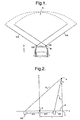
- an automotive vehicle 10 having a collision detection system for detecting and tracking an object, and detecting the potential for a collision with the object.
- the collision detection system includes first and second radar sensors 12A and 12B mounted to the host vehicle 10 to cover a desired field of view in front of the vehicle 10.
- the vehicle collision detection system senses and tracks one or more objects, such as a moving target, and estimates a crossing location of the target object relative to a baseline axis of the vehicle 10. Using the estimated crossing location of the object, the collision detection system is able to detect an anticipated collision of the target object 16 with the host vehicle 10, thereby allowing for responsive countermeasure action(s) to be taken.
- the sensor arrangement includes the first and second sensors 12A and 12B mounted on opposite sides of the front bumper of vehicle 10, according to one embodiment.
- the first radar sensor 12A senses objects in a first field of view 14A
- the second sensor 12B senses objects in a second field of view 14B.
- the first and second field of views 14A and 14B substantially overlap to provide a common coverage zone field of view 15.
- Sensors 12A and 12B sense the presence of one or more objects in field of view 15, track relative movement of each of the sensed objects within field of view 15, and measure the range (radial distance) to the target object from each sensor. Additionally, sensors 12A and 12B may further measure the range rate (time rate of change of radial distance) of the target object.
- the first and second sensors 12A and 12B are shown separated from each other by a distance d and aligned on a baseline B extending through sensors 12A and 12B along the y-axis.
- An x-axis is shown extending through a center point O midway between sensors 12A and 12B, orthogonal to the y-axis.
- a target object 16 is illustrated and is assumed to have a relative velocity vector (relative to the vehicle) parallel to the longitudinal axis (X-axis) of the vehicle 10 as shown by speed vector S.
- First sensor 12A senses the range R 1 defined as the radial distance between first sensor 12A and object 16.
- the first sensor 12A may also sense the range rate R & 1 as the measured rate of change of range R 1 of the object 16 as a function of time relative to the host vehicle 10.
- Second sensor 12B measures range R 2 defined as the radial distance between second sensor 12B and target object 16.
- the second sensor 12B may likewise measure the range rate R & 2 as the measured rate of change of the range R 2 of the object 16 as a function of time relative to the host vehicle 10.
- the range rates R & 1 and R & 2 may be determined by computing the time rate of change (i.e., derivative) of the corresponding sensed ranges R 1 and R 2 , respectively.
- the first and second sensors 12A and 12B may each include a commercially available off-the-shelf wide-beam staring microwave Doppler radar sensor.
- object detecting sensors including other types of radar sensors, video imaging cameras, and laser sensors may be employed to detect the presence of an object, track the relative movement of the detected object, and determine the range measurements R 1 and R 2 , and range rate measurements ⁇ 1 and ⁇ 2 that are processed according to the present invention.
- the target object 16 is shown having an estimated crossing of the baseline B at a location C with a crossing location distance L from center point O.
- the crossing location distance L can also be expressed as the distance from the point O midway between sensors 12A and 12B (e.g., center of bumper) and crossing location C.
- the collision detection system and method of the present invention advantageously estimates the crossing location C of the target object 16 as a function of range and range rate measurements, without the requirement of acquiring an azimuth angle measurement of the object 16.
- the collision detection system of the present invention is able to use a reduced complexity and less costly sensing arrangement, while obtaining a crossing location C estimation. While a pair of sensors 12A and 12B are shown, it should be appreciated that any number of two or more sensors may be employed to estimate the crossing location C of one or more target objects.
- the collision detection system may assume that the object 16 is a point reflector having a relative velocity vector S substantially parallel to the longitudinal axis of the vehicle 10, which is the anticipated axis of travel of the vehicle 10.
- the crossing location C is the signed lateral coordinate of the target object 16 where the object 16 is expected to cross the sensor baseline B (the line passing through the two sensors 12A and 12B along the y-axis).
- the side of the vehicle 10 to be affected by a potential collision can be determined based on the estimated crossing location C.
- the crossing location C R 1 2 - R 2 2 2 ⁇ d
- the crossing location C is determined as the distance midway between sensors 12A and 12B to the crossing point on baseline B.
- the crossing location C of the target object 16 is determined as described herein according to first and second embodiments of the present invention.
- Controller 20 preferably includes a microprocessor-based controller having microprocessor 22 and memory 24.
- Memory 24 may include random access memory (RAM), read-only memory (ROM), and electrically erasable programmable read-only memory (EEPROM).
- Controller 20 may be a commercially available off-the-shelf controller and may be dedicated to any one or more of target tracking, adaptive cruise control, and crash processing, according to some examples, or may share processing capability with other vehicle functions.
- the controller 20 receives the range measurement R 1 and range rate measurement R & 1 from first radar sensor 12A, and likewise receives the range measurement R 2 and range rate measurement R & 2 from the second radar sensor 12B. Controller 20 processes the received range measurements R 1 and R 2 and range rate measurements R & 1 and R & 2 with a crossing location estimation routine according to the present invention. The controller 20 may further process the estimated crossing location estimation C to initiate countermeasures.
- the controller 20 generates an output signal 26 in the event that an anticipated vehicle collision has been determined.
- the output signal 26 may be supplied as an input to one or more devices in the vehicle, such as an adaptive cruise control system 28, seat belt pretensioner 30, and one or more warning devices 32.
- the adaptive cruise control system 28 may employ the estimated crossing location C of object 16 to control speed of the host vehicle 10.
- the seat belt pretensioner may be controlled to pretension the seat belt just prior to an anticipated vehicle collision to eliminate slack in the restraining device, and may deploy only certain restraining devices based on the estimated crossing location C.
- the one or more warning devices 30 may be employed to warn the vehicle operator and occupants of an anticipated vehicle collision and the estimated location C of impact on the host vehicle 10. It should be appreciated that other devices may be deployed responsive to signal 26 including vehicle air bags, pop-up roll bars, as well as other safety-related devices.
- a target crossing location estimator 34 is generally shown receiving the range measurements R 1 and R 2 and range rate measurements ⁇ 1 and ⁇ 2 , generated by first and second sensors 12A and 12B.
- the range and range rate measurements R 1 and R 2 and ⁇ 1 and ⁇ 2 are processed by the estimator 34, which includes a programmed routine 40 estimating a crossing location C of the object relative to the baseline B of the sensors 12A and 12B. Further, the estimator 34 may estimate target speed S of the target object.
- the crossing location estimation of the present invention assumes that the target object is moving straight and at a constant speed generally parallel to the longitudinal axis of the host vehicle 10.
- the crossing location estimation assumes that the target object 16 is a point reflector having a velocity vector relative to the host vehicle 10 that is substantially parallel to the vehicle longitudinal axis.
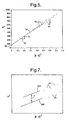
- the W-plane is shown as a plane having data plotted on horizontal and vertical coordinates for data measured with one of sensors 12A and 12B. While data from one of sensors 12A and 12B is shown in FIG. 5 , it should be appreciated that data from both sensors 12A and 12B is processed.
- the vertical coordinate represents the squared range R 2 values
- the horizontal coordinate represents the squared product of range and range rate (R ⁇ ⁇ ) 2 values.
- the pairs of computed values for each of data measurements may be plotted in the W-plane as shown by points 64 for X number of measurements taken with each of sensors 12A and 12B.
- a least-squares fit line 66 is generated based on a close fit to the plurality of plotted measurements 64.
- the speed S may be estimated from an interpretation of the fitted curve 66.
- 1 S 2 represents the slope of curve 66 as defined by horizontal segment 70 and vertical segment 72. Accordingly, the speed S of the object relative to the host vehicle may be estimated based on the slope of curve 66. While a straight line curve 66 is shown in FIG. 5 , it should be appreciated that some higher-order curve may be employed to define the relationship of the sample points.
- the collision detection system of the present invention advantageously estimates the crossing location C of the target object 16, which is the location at which the object is estimated to cross the baseline B of the first and second sensors 12A and 12B.
- the crossing location C is determined from a point O midway between the two sensors 12A and 12B.
- the controller 20 is able to estimate where the target object 16 may impact the host vehicle 10. This enables the controller 20 to take pre-emptive action such as to avoid the accident and/or initiate certain devices in anticipation of a collision at the estimated crossing location C.
- the estimated crossing location C of the object 16 is estimated according to a first embodiment shown in FIGS. 6 and 7 , and according to a second embodiment shown in FIGS. 8 and 9 .
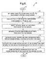
- Routine 80 for estimating the crossing location C of a target object is shown according to the first embodiment of the present invention.
- Routine 80 employs the data plotted in the W-plane for both of sensors 12A and 12B.
- One example of data plotted in the W-plane for both of sensors 12A and 12B is shown in FIG. 7 .
- a least-squares line 66A is drawn through the data representing measurements taken with the first sensor 12A.
- a least-squares line 66B is determined with respect to the data representing measurements taken with the second sensor 12B.
- Routine 80 begins at step 82 and proceeds to get the current range measurement R 1 and R 2 and range rate measurements ⁇ 1 and ⁇ 2 sensed by first and second radar sensors in step 84.
- Routine 80 may associate data with the particular target object by way of an object tracker.
- the object tracker tracks each object based on the combination of range and range rate measurements taken with each of first and second sensors 12A and 12B. If the current range and range rate measurements are sufficiently close in value to the predicted range and range rate values, the object measurement data is assumed to pertain to the same object.
- the tracking of each detected object with each sensor allows for a consistent stream of measurement data at incremental time periods k, k+1, k+2, etc. for each sensed object.
- step 86 the W-plane quantities corresponding to measurements for each of the first and second sensors are calculated which include the W-plane quantities of R 2 and (R ⁇ ⁇ ) 2 in step 86.
- routine 80 selects the N most recent W-plane points from data measured with each of the two sensors 12A and 12B.
- the squared range and squared product of range and rate values, R 2 and (R ⁇ ⁇ ) 2 , respectively, for each of N measurements taken by each of first and second sensors 12A and 12B are preferably stored in memory and are processed by controller 20 as explained herein. It should be appreciated that the number (N) of measurements may include thirty, according to one example, or may include fewer or greater number of measurements for each of the sensors 12A and 12B.
- the processing of a greater number of measurements may result in less noise, but may be less responsive to maneuvers between the object and the host vehicle. Accordingly, the number (N) of measurements from each of first and second sensors 12A and 12B that are processed is a compromise and may vary depending on the application.
- Routine 80 may include optional step 90 of discarding one or more outlier data points from each of the two sensors.
- the outlier removal enhancement may remove one or more data points from each window, after identifying them as being in substantial disagreement with the other data points of the window. This is done before calculating the least-squares line for each window.
- routine 80 calculates a least-squares line for each sensor using the remaining data points in each window. That is, the data measured with sensor 12A is used to calculate a first least-squares line 66A, while the data measured with sensor 12B is used to calculate a second least-squares line 66B.
- the least-squares lines 66A and 66B corresponding to the first and second sensors 12A and 12B, respectively, which are shown in one example in FIG. 7 may be adjusted to constrain the slope of the lines 66A and 66B to be equal to one another. By constraining the two least-squares line 66A and 66B to have the same slope, enhanced accuracy of the crossing location estimation can be achieved.
- the slope of the W-plane trace is the inverse of the target's relative speed squared. Because of this relationship, if the data from two sensors tracking the same point target are plotted in the W-plane, the resulting traces should be parallel.
- routine 80 calculates the W-plane vertical distance V which is the vertical distance between the two lines 66A and 66B in the neighborhood (window) of the two sets of points for the corresponding two sensors.
- the vertical distance V is preferably taken near the center of the windowed lines 66A and 66B.
- routine 80 divides the vertical separation V by twice the separation distance 2d of sensors 12A and 12B to obtain the crossing location C. According to the embodiment shown, the crossing location C is determined relative to the point O midway between the two sensors 12A and 12B.
- the crossing location C of the target object 16 is negative, that is, it is on the driver side of the vehicle, according to one arrangement.
- the crossing location C of the target object 16 is positive, that is, it is on the passenger side of the vehicle, as compared to the driver side.
- the first embodiment employing the vertical separation technique in the W-plane may be generally less sensitive to maneuvers and accelerations. In this approach, only the vertical separation is required to estimate the crossing location, and since the two ideal measurement curves 66A and 66B are similarly shaped, any ill effects of the fitted lines approximately cancel out. Additionally, the W-plane approach is generally insensitive to any distributed nature of the target.
- the time-domain approach to estimating the crossing location employs an estimator 34' having tracking filters 100 and 102 coupled to corresponding radar sensors 12A and 12B to produce a range R estimate for each sensor.
- the tracking filters 100 and 102 may also receive range rate ⁇ ; however, the tracking filters 100 and 102 may operate without range rate.
- the estimator 34' further includes mathematical square functions 104 and 106 for calculating the mathematical square of the outputs of tracking filters 100 and 102, respectively.
- a subtractor 108 computes the difference between the outputs of square functions 104 and 106.
- estimator 34' employs a divider 110 for dividing the computed difference by twice the separation distance (2d) of sensors 12A and 12B.
- the output of divider 110 is applied to a low pass filter 112 to provide the crossing location estimate C in block 114.
- Routine 120 begins at step 122 and proceeds to step 124 to get the range measurements R 1 and R 2 from both radar sensors 12A and 12B.
- range rate ⁇ 1 and ⁇ 2 measurements may also be obtained.
- routine 120 processes each set of radar sensor measurements from sensors 12A and 12B using the range tracking filters 100 and 102, respectively.
- the filters 100 and 102 may optionally also use the range rate measurements ⁇ 1 and ⁇ 2 which may offer enhanced estimation of the crossing location.
- routine 120 proceeds to step 128 to find the difference of the squares of the two current range estimates from the tracking filters. This is performed by the subtractor 108.
- routine 120 divides the difference by twice the sensor separation distance 2d.
- step 132 the divided difference is low pass filtered to get the estimated crossing location C. Routine 120 is then completed in step 134.
- the time-approach estimation 34' advantageously does not require range rate measurements from sensors 12A and 12B to obtain an estimation of the crossing location C. If sufficient range rate information is available from sensors 12A and 12B, such range rate information may advantageously enhance the tracking filter processing.
- the collision detection system of the present invention advantageously estimates the crossing location C in a simplified and cost affordable system.
- the present collision detection system quickly estimates the crossing location C much faster than prior known approaches.
- the collision detection system of the present invention handles maneuvers and accelerations better than prior known single-sensor approaches.
Abstract
Description
- The present invention generally relates to object collision detection and, more particularly, relates to a collision detection system and method of estimating the crossing location of the object.
- Automotive vehicles are increasingly being equipped with collision avoidance and warning systems for predicting potential collisions with external objects, such as another vehicle or a pedestrian. Upon detecting a potential collision, such systems are capable of initiating an action to avoid the collision, minimize impact with the object, and/or provide a warning to the vehicle operator. Adaptive cruise control systems have been proposed to track a leading vehicle and automatically control the speed of the following vehicle. The ability to accurately predict an upcoming collision also enables a vehicle controller to control and deploy safety-related devices on the host vehicle. For example, upon predicting an anticipated collision or near collision with an object, the vehicle seat belt pretensioner could be activated in a timely manner to pretension the seat belt, or the air bag system could be readied for quicker activation, thereby enhancing the application of the safety devices. The controller could also deploy a warning signal to notify the vehicle driver of a predicted collision with an object.
- In some vehicle target tracking systems, the host vehicle is generally equipped with a sensor arrangement that acquires range, range rate, and azimuth angle (i.e., direction to target) measurements for each tracked target within a field of view. The sensor arrangement employed in such conventional systems generally requires a relatively complex and expensive sensor arrangement employing multiple sensors that are required to measure the azimuth angle of the object, relative to the host vehicle, in addition to obtaining range and range rate measurements of the object. It is generally desirable to reduce the complexity and cost of systems and components employed on automotive vehicles to provide a cost affordable vehicle to consumers.
- It has been proposed to reduce the complexity and cost of a vehicle collision detection system by employing a single radar sensor that provides range and range rate measurements of an object and estimates the miss distance of the object. One such approach is disclosed in
U.S. Patent No. 6,615,138 , and entitled "COLLISION DETECTION SYSTEM AND METHOD OF ESTIMATING MISS DISTANCE EMPLOYING CURVE FITTING." Another approach is disclosed inU.S. Application Serial No. 10/158,550, filed on May 30, 2002 US-A-7016782 . While the aforementioned approaches employing a single radar sensor are well suited to estimate the miss distance of an object, additional information such as the crossing location with respect to the vehicle is generally not available. In some situations, it may be desirable to determine the crossing location of the object with respect to the host vehicle, such as a location on the vehicle front bumper that the object is expected to come into contact with. By knowing the location of the expected collision, countermeasures can be initiated based on the anticipated crossing location. - It is therefore desirable to provide for a vehicle collision detection system that estimates the crossing location of an object. It is further desirable to provide for a reduced complexity and cost affordable vehicle collision detection system that estimates crossing location of an object.
-
US-A-6087928 discloses a system and method in accordance with the preamble ofclaims 1 and 9 respectively.US-A-5872536 discloses a multi-sensor anticipatory object detection system for detecting range velocity collision angle and point of impact of a colliding object.EP-A-0899583 discloses an antenna cluster for a vehicle collision warning system. - In accordance with the teachings of the present invention, a collision detection system and method of estimating a crossing location of an object are provided. According to one aspect of the present invention, the collision detection system includes a first sensor for sensing an object in a field of view and measuring a first range defined as the distance between the object and the first sensor. The system also includes a second sensor for sensing the object in the field of view and measuring a second range defined by the distance between the object and the second sensor. The system further includes a controller for processing the first and second range measurements and estimating a crossing location of the object as a function of the first and second range measurements.
- According to another aspect of the present invention, a method of estimating a crossing location of an object is provided. The method includes the steps of sensing the presence of an object in a field of view, tracking the object with first and second sensors, measuring range to the object with the first sensor, and measuring range to the object with the second sensor. The first and second sensors are separate from each other. The method further includes the step of estimating a crossing location of the object as a function of the range measurement with the first and second sensors.
- Accordingly, the collision detection system and method of estimating target crossing location of the present invention advantageously estimates the crossing location of an object without requiring a complex and costly sensor arrangement. By knowing the target crossing location, the present invention advantageously allows for enhanced countermeasures to be employed on a vehicle.
- These and other features, advantages and objects of the present invention will be further understood and appreciated by those skilled in the art by reference to the following specification, claims and appended drawings.
- The present invention will now be described, by way of example, with reference to the accompanying drawings, in which:
-
FIG. 1 is a plan view illustrating the geometry of a collision detection system employing two sensors on a vehicle according to the present invention; -
FIG. 2 is a plan view further illustrating the geometry of the detection system shown tracking a target object; -
FIG. 3 is a block diagram illustrating the collision detection system; -
FIG. 4 is a block diagram illustrating the target crossing location estimator of the collision detection system; -
FIG. 5 is a graph illustrating sensed data plotted in a curve in a W-plane; -
FIG. 6 is a flow diagram illustrating a routine for estimating the crossing location of the target object using the W-plane according to the first embodiment of the present invention; -
FIG. 7 is a graph illustrating estimation of the target crossing location according to the first embodiment of the present invention; -
FIG. 8 is a block diagram illustrating a time-domain approach to estimating the crossing location of a target object according to a second embodiment of the present invention; and -
FIG. 9 is a flow diagram illustrating a routine for estimating the target crossing location according to the second embodiment of the present invention. - Referring to
FIG. 1 , anautomotive vehicle 10 is generally illustrated having a collision detection system for detecting and tracking an object, and detecting the potential for a collision with the object. The collision detection system includes first andsecond radar sensors host vehicle 10 to cover a desired field of view in front of thevehicle 10. The vehicle collision detection system senses and tracks one or more objects, such as a moving target, and estimates a crossing location of the target object relative to a baseline axis of thevehicle 10. Using the estimated crossing location of the object, the collision detection system is able to detect an anticipated collision of thetarget object 16 with thehost vehicle 10, thereby allowing for responsive countermeasure action(s) to be taken. - The sensor arrangement includes the first and
second sensors vehicle 10, according to one embodiment. Thefirst radar sensor 12A senses objects in a first field of view 14A, and thesecond sensor 12B senses objects in a second field of view 14B. The first and second field of views 14A and 14B substantially overlap to provide a common coverage zone field ofview 15.Sensors view 15, track relative movement of each of the sensed objects within field ofview 15, and measure the range (radial distance) to the target object from each sensor. Additionally,sensors - Referring to
FIG. 2 , the first andsecond sensors sensors sensors target object 16 is illustrated and is assumed to have a relative velocity vector (relative to the vehicle) parallel to the longitudinal axis (X-axis) of thevehicle 10 as shown by speed vector S.First sensor 12A senses the range R1 defined as the radial distance betweenfirst sensor 12A andobject 16. Thefirst sensor 12A may also sense the range rate R& 1 as the measured rate of change of range R1 of theobject 16 as a function of time relative to thehost vehicle 10.Second sensor 12B measures range R2 defined as the radial distance betweensecond sensor 12B andtarget object 16. Thesecond sensor 12B may likewise measure the range rate R& 2 as the measured rate of change of the range R2 of theobject 16 as a function of time relative to thehost vehicle 10. Alternately, the range rates R& 1 and R& 2 may be determined by computing the time rate of change (i.e., derivative) of the corresponding sensed ranges R1 and R2, respectively. - The first and
second sensors target object 16 is shown having an estimated crossing of the baseline B at a location C with a crossing location distance L from center point O. The crossing location distance L can also be expressed as the distance from the point O midway betweensensors - The collision detection system and method of the present invention advantageously estimates the crossing location C of the
target object 16 as a function of range and range rate measurements, without the requirement of acquiring an azimuth angle measurement of theobject 16. Thus, the collision detection system of the present invention is able to use a reduced complexity and less costly sensing arrangement, while obtaining a crossing location C estimation. While a pair ofsensors - In order to track
object 16 incoverage zone 15, the collision detection system may assume that theobject 16 is a point reflector having a relative velocity vector S substantially parallel to the longitudinal axis of thevehicle 10, which is the anticipated axis of travel of thevehicle 10. The crossing location C is the signed lateral coordinate of thetarget object 16 where theobject 16 is expected to cross the sensor baseline B (the line passing through the twosensors sensors host vehicle 10, the side of thevehicle 10 to be affected by a potential collision can be determined based on the estimated crossing location C. - Based on the assumption that the
target object 16 is assumed to have a relative velocity vector which is roughly parallel to thehost vehicle 10 longitudinal axis, the following equation defines the crossing location
sensors target object 16 is determined as described herein according to first and second embodiments of the present invention. - Referring to
FIG. 3 , thecollision detection system 18 is shown includingradar sensors controller 20.Controller 20 preferably includes a microprocessor-basedcontroller having microprocessor 22 andmemory 24.Memory 24 may include random access memory (RAM), read-only memory (ROM), and electrically erasable programmable read-only memory (EEPROM).Controller 20 may be a commercially available off-the-shelf controller and may be dedicated to any one or more of target tracking, adaptive cruise control, and crash processing, according to some examples, or may share processing capability with other vehicle functions. - The
controller 20 receives the range measurement R1 and range rate measurement R& 1 fromfirst radar sensor 12A, and likewise receives the range measurement R2 and range rate measurement R& 2 from thesecond radar sensor 12B.Controller 20 processes the received range measurements R1 and R2 and range rate measurements R& 1 and R& 2 with a crossing location estimation routine according to the present invention. Thecontroller 20 may further process the estimated crossing location estimation C to initiate countermeasures. - The
controller 20 generates anoutput signal 26 in the event that an anticipated vehicle collision has been determined. Theoutput signal 26 may be supplied as an input to one or more devices in the vehicle, such as an adaptivecruise control system 28,seat belt pretensioner 30, and one ormore warning devices 32. The adaptivecruise control system 28 may employ the estimated crossing location C ofobject 16 to control speed of thehost vehicle 10. The seat belt pretensioner may be controlled to pretension the seat belt just prior to an anticipated vehicle collision to eliminate slack in the restraining device, and may deploy only certain restraining devices based on the estimated crossing location C. The one ormore warning devices 30 may be employed to warn the vehicle operator and occupants of an anticipated vehicle collision and the estimated location C of impact on thehost vehicle 10. It should be appreciated that other devices may be deployed responsive to signal 26 including vehicle air bags, pop-up roll bars, as well as other safety-related devices. - Referring to
FIG. 4 , a targetcrossing location estimator 34 is generally shown receiving the range measurements R1 and R2 and range rate measurements Ṙ1 and Ṙ2, generated by first andsecond sensors - The range and range rate measurements R1 and R2 and Ṙ1 and Ṙ2 are processed by the
estimator 34, which includes a programmed routine 40 estimating a crossing location C of the object relative to the baseline B of thesensors estimator 34 may estimate target speed S of the target object. - The crossing location estimation of the present invention assumes that the target object is moving straight and at a constant speed generally parallel to the longitudinal axis of the
host vehicle 10. The crossing location estimation assumes that thetarget object 16 is a point reflector having a velocity vector relative to thehost vehicle 10 that is substantially parallel to the vehicle longitudinal axis. - Referring to
FIG. 5 , the W-plane is shown as a plane having data plotted on horizontal and vertical coordinates for data measured with one ofsensors sensors FIG. 5 , it should be appreciated that data from bothsensors points 64 for X number of measurements taken with each ofsensors fit line 66 is generated based on a close fit to the plurality of plottedmeasurements 64. - While a least-squares fit line is shown and described herein in connection with the W-plane, it should be appreciated that other curves, both linear and non-linear, may be defined based on the pairs of data for
N measurements 64, without departing from the teachings of the present invention. Further, while a plot is shown in the W-plane, it should be appreciated that thecontroller 20 may process the data measured via first andsecond sensors controller 20. - The speed S may be estimated from an interpretation of the fitted
curve 66.
curve 66 as defined byhorizontal segment 70 andvertical segment 72. Accordingly, the speed S of the object relative to the host vehicle may be estimated based on the slope ofcurve 66. While astraight line curve 66 is shown inFIG. 5 , it should be appreciated that some higher-order curve may be employed to define the relationship of the sample points. - The collision detection system of the present invention advantageously estimates the crossing location C of the
target object 16, which is the location at which the object is estimated to cross the baseline B of the first andsecond sensors sensors object 16, thecontroller 20 is able to estimate where thetarget object 16 may impact thehost vehicle 10. This enables thecontroller 20 to take pre-emptive action such as to avoid the accident and/or initiate certain devices in anticipation of a collision at the estimated crossing location C. The estimated crossing location C of theobject 16 is estimated according to a first embodiment shown inFIGS. 6 and7 , and according to a second embodiment shown inFIGS. 8 and 9 . - Referring to
FIG. 6 , a routine 80 for estimating the crossing location C of a target object is shown according to the first embodiment of the present invention.Routine 80 employs the data plotted in the W-plane for both ofsensors sensors FIG. 7 . As seen inFIG. 7 , a least-squares line 66A is drawn through the data representing measurements taken with thefirst sensor 12A. Likewise, a least-squares line 66B is determined with respect to the data representing measurements taken with thesecond sensor 12B. -
Routine 80 begins atstep 82 and proceeds to get the current range measurement R1 and R2 and range rate measurements Ṙ1 and Ṙ2 sensed by first and second radar sensors instep 84.Routine 80 may associate data with the particular target object by way of an object tracker. The object tracker tracks each object based on the combination of range and range rate measurements taken with each of first andsecond sensors - In
step 86, the W-plane quantities corresponding to measurements for each of the first and second sensors are calculated which include the W-plane quantities of R2 and (R· Ṙ)2 instep 86. Instep 88, routine 80 selects the N most recent W-plane points from data measured with each of the twosensors second sensors controller 20 as explained herein. It should be appreciated that the number (N) of measurements may include thirty, according to one example, or may include fewer or greater number of measurements for each of thesensors second sensors -
Routine 80 may includeoptional step 90 of discarding one or more outlier data points from each of the two sensors. The outlier removal enhancement may remove one or more data points from each window, after identifying them as being in substantial disagreement with the other data points of the window. This is done before calculating the least-squares line for each window. - Proceeding to step 92, routine 80 calculates a least-squares line for each sensor using the remaining data points in each window. That is, the data measured with
sensor 12A is used to calculate a first least-squares line 66A, while the data measured withsensor 12B is used to calculate a second least-squares line 66B. The least-squares lines second sensors FIG. 7 , may be adjusted to constrain the slope of thelines squares line - Next, in
step 94, routine 80 calculates the W-plane vertical distance V which is the vertical distance between the twolines windowed lines step 96, routine 80 divides the vertical separation V by twice theseparation distance 2d ofsensors sensors - According to one example, if
line 66B corresponding tosensor 12B is belowlines 66A corresponding tosensor 12A, then the crossing location C of thetarget object 16 is negative, that is, it is on the driver side of the vehicle, according to one arrangement. Thus, ifline 66A corresponding tosensor 12A is belowline 66B corresponding tosensor 12B, then the crossing location C of thetarget object 16 is positive, that is, it is on the passenger side of the vehicle, as compared to the driver side. By knowing which side of the vehicle the object is expected to collide with, enhanced countermeasures can be initiated. - The first embodiment employing the vertical separation technique in the W-plane may be generally less sensitive to maneuvers and accelerations. In this approach, only the vertical separation is required to estimate the crossing location, and since the two
ideal measurement curves - Referring to
FIGS. 8 and 9 , a time-domain approach to estimating the crossing location C of atarget object 16 is shown according to the second embodiment of the present invention. The time-domain approach to estimating the crossing location employs an estimator 34' havingtracking filters radar sensors square functions filters subtractor 108 computes the difference between the outputs ofsquare functions divider 110 for dividing the computed difference by twice the separation distance (2d) ofsensors divider 110 is applied to alow pass filter 112 to provide the crossing location estimate C inblock 114. - Referring to
FIG. 9 , a routine 120 is shown for estimating the crossing location C of a target object employing estimator 34' according to the second embodiment.Routine 120 begins atstep 122 and proceeds to step 124 to get the range measurements R1 and R2 from bothradar sensors sensors filters - Next, routine 120 proceeds to step 128 to find the difference of the squares of the two current range estimates from the tracking filters. This is performed by the
subtractor 108. Next, instep 130, routine 120 divides the difference by twice thesensor separation distance 2d. Instep 132, the divided difference is low pass filtered to get the estimated crossinglocation C. Routine 120 is then completed instep 134. - The time-approach estimation 34' advantageously does not require range rate measurements from
sensors sensors - Accordingly, the collision detection system of the present invention advantageously estimates the crossing location C in a simplified and cost affordable system. The present collision detection system quickly estimates the crossing location C much faster than prior known approaches. Additionally, the collision detection system of the present invention handles maneuvers and accelerations better than prior known single-sensor approaches. By quickly and accurately determining the crossing location C of an object with respect to the
host vehicle 10, the system is able to quickly initiate countermeasures which may occur based on the estimated location of a potential collision.
Claims (8)
- A collision detection system for a vehicle incorporating a target crossing location estimator comprising: a first sensor (12A) configured to sense an object (16) in a field of view (15) and provide signals of a measurement of a first range, defined as the distance between the object and the first sensor, and a determination of a first range rate thereof; a second sensor (12B) configured to sense the object in the field of view and provide signals of a measurement of a second range, defined by the distance between the object and the second sensor, and a determination of a second range rate thereof, the first and second sensors defining a baseline (B); and a controller (20) configured to receive a plurality of paired range and range rate signals for the sensed object from the first sensor and a plurality of paired range and range rate signals for the sensed object from the second sensor over a time period, characterized in that:the controller is further configured to compute for each of the received paired range and range rate signals a square of the range and a square of the product of range and range rate, the controller deriving an estimated target crossing point location along the baseline as a distance from a predetermined point on the baseline, wherein the predetermined point is a location (0) midway between the first and second sensors (12A, 12B), the distance being derived as a function of a comparison of the computed square of the range and the computed square of the product of range and range rate associated with sensed signals from the first and second sensors, and the controller further generating a signal based on the estimated crossing point location,wherein the controller further computes a W-plane point representing the square of the range and the square of the product of range and range rate, wherein the W-plane is a two-dimensional Cartesian coordinate system with a first axis representing the square of range and a perpendicular second axis representing the square of the product of range and range rate, the controller generating a first best-fit W-plane curve from the W-plane points derived from the first sensor and a second best-fit W-plane curve from the W-plane points derived from the second sensor, the controller further calculating a numerical difference between values of the first and second best-fit W-plane curves at a selected value of the square of the product of range and range rate, and deriving the estimated target crossing point location along the baseline as the distance from the location (o) midway between the first and second sensors (12A and 12B), the distance being derived from the numerical difference and a separation distance of the first and second sensors,wherein the crossing location (C) of the object (16) is estimated as a function of the distance (V) between the first and second curves (66A and 66B), andwherein the crossing location (C) is estimated by dividing the distance (V) between the first and second curves (66A and 66B) by twice the separation distance (2d) of the first and second sensors (12A and 12B).
- The collision detection system as defined in claim 1, wherein the first and second best-fit W-plane curves are constrained to be linear and parallel.
- The collision detection system as defined in claim 1, wherein the reference point is a midpoint of the baseline between the first and second sensors and the controller is configured to derive the distance as the numerical difference divided by twice the separation distance of the first and second sensors.
- The collision detection system as defined in claim 1, wherein each of the first and second sensors comprises a radar sensor.
- The collision detection system as defined in claim 1, wherein the controller is not configured to receive an azimuth angle measurement of the object.
- A method of estimating a crossing location (C) of an object (16), said method comprising the steps of: sensing with a first sensor (12A) an object (16) in a field of view (15) and providing signals of a measurement of a first range defined as the distance between the object and the first sensor and a determination of a first range rate thereof, sensing the object (16) in the field of view (15) with the second sensor (128) and providing signals of a measurement of a second range defined by the distance between the object and the second sensor and a determination of a second range rate thereof the first and second sensors defining a baseline (B), and processing paired range and range rate signals from the first sensor and paired range and range rate signals from the second sensor over a time period, characterized in that:the method further computes, for each of the received paired range and range rate signals received over a time period, a square of the range and a square of the product of range and range rate, derives an estimated target crossing point location along the baseline as a distance from a predetermined point on the baseline, wherein the predetermined point is a location (0) midway between the first and second sensors (12A, 12B), the distance being derived from a comparison of the computed square of the range and the square of the product of range and range rate for signals associated with the first and second sensors, and generating a signal based on the estimated crossing point location, andfurther comprising the steps of computing a W-plane point representing the square of the range and the square of the product of range and range rate, wherein the W-plane is a two-dimensional Cartesian coordinate system with a first axis representing the square of range and a perpendicular second axis representing the square of the product of range and range rate, generating a first best-fit W-plane curve from the W-plane points derived from the first sensor and a second best-fit W-plane curve from the W-plane points derived form the second sensor, and calculating a numerical difference between values of the first and second best-fit W-plane curves at a selected value of the square of the product of range and range rate,wherein the reference point is a midpoint of the baseline between the first and second sensors and the distance is derived as the numerical difference divided by twice the separation distance of the first and second sensors.
- The method as defined in claim 6, wherein the method estimates the crossing location (C) of the object (16) relative to a vehicle (10).
- The method as defined in claim 6 further comprising the step of generating a collision output signal (26) as a function of the estimated crossing location (C).
Applications Claiming Priority (2)
| Application Number | Priority Date | Filing Date | Title |
|---|---|---|---|
| US780845 | 2004-02-18 | ||
| US10/780,845 US7369941B2 (en) | 2004-02-18 | 2004-02-18 | Collision detection system and method of estimating target crossing location |
Publications (3)
| Publication Number | Publication Date |
|---|---|
| EP1566657A2 EP1566657A2 (en) | 2005-08-24 |
| EP1566657A3 EP1566657A3 (en) | 2006-05-24 |
| EP1566657B1 true EP1566657B1 (en) | 2011-06-29 |
Family
ID=34711845
Family Applications (1)
| Application Number | Title | Priority Date | Filing Date |
|---|---|---|---|
| EP05075296A Active EP1566657B1 (en) | 2004-02-18 | 2005-02-04 | Collision detection system and method of estimating target crossing location |
Country Status (3)
| Country | Link |
|---|---|
| US (2) | US7369941B2 (en) |
| EP (1) | EP1566657B1 (en) |
| AT (1) | ATE514960T1 (en) |
Cited By (1)
| Publication number | Priority date | Publication date | Assignee | Title |
|---|---|---|---|---|
| US11762084B2 (en) | 2016-07-08 | 2023-09-19 | Arriver Software Ab | Vehicle radar system |
Families Citing this family (40)
| Publication number | Priority date | Publication date | Assignee | Title |
|---|---|---|---|---|
| JP2006189393A (en) * | 2005-01-07 | 2006-07-20 | Toyota Motor Corp | Peripheral object information acquiring device, and parking support device using same |
| JP4371115B2 (en) * | 2006-03-01 | 2009-11-25 | トヨタ自動車株式会社 | Object detection device |
| US20070255498A1 (en) * | 2006-04-28 | 2007-11-01 | Caterpillar Inc. | Systems and methods for determining threshold warning distances for collision avoidance |
| US7567168B2 (en) * | 2006-10-24 | 2009-07-28 | Shih-Hsiung Li | Car reversal radar that automatically modifies the sensor scanning range and method of the same |
| JP4254844B2 (en) * | 2006-11-01 | 2009-04-15 | トヨタ自動車株式会社 | Travel control plan evaluation device |
| JP4371137B2 (en) * | 2006-11-10 | 2009-11-25 | トヨタ自動車株式会社 | Automatic operation control device |
| JP4525670B2 (en) * | 2006-11-20 | 2010-08-18 | トヨタ自動車株式会社 | Travel control plan generation system |
| US8447472B2 (en) * | 2007-01-16 | 2013-05-21 | Ford Global Technologies, Llc | Method and system for impact time and velocity prediction |
| US8515659B2 (en) * | 2007-03-29 | 2013-08-20 | Toyota Jidosha Kabushiki Kaisha | Collision possibility acquiring device, and collision possibility acquiring method |
| JP4450023B2 (en) | 2007-07-12 | 2010-04-14 | トヨタ自動車株式会社 | Own vehicle risk acquisition device |
| JP2009031078A (en) * | 2007-07-26 | 2009-02-12 | Omron Corp | Device and method for detection |
| TWI348555B (en) * | 2007-10-30 | 2011-09-11 | Univ Nat Taiwan | Target detection device and its detection method |
| US7512516B1 (en) | 2007-11-02 | 2009-03-31 | Delphi Technologies, Inc. | Collision avoidance and warning system and method |
| US8451140B2 (en) * | 2007-12-20 | 2013-05-28 | International Business Machines Corporation | Monitoring road surface conditions |
| US20090164063A1 (en) * | 2007-12-20 | 2009-06-25 | International Business Machines Corporation | Vehicle-mounted tool for monitoring road surface defects |
| WO2010064282A1 (en) * | 2008-12-05 | 2010-06-10 | トヨタ自動車株式会社 | Pre-crash safety system |
| WO2010067397A1 (en) * | 2008-12-09 | 2010-06-17 | トヨタ自動車株式会社 | Object detection device and object detection method |
| DE112009004346B4 (en) * | 2009-01-29 | 2014-05-28 | Toyota Jidosha Kabushiki Kaisha | Object recognition device and object recognition method |
| JP4748232B2 (en) * | 2009-02-27 | 2011-08-17 | トヨタ自動車株式会社 | Driving assistance device |
| US8334758B2 (en) * | 2009-04-13 | 2012-12-18 | Flextronics Automotive, Inc. | LIN BUS remote control system |
| CN102449672B (en) | 2009-06-02 | 2013-05-01 | 丰田自动车株式会社 | Vehicular peripheral surveillance device |
| DE102010062235A1 (en) | 2010-12-01 | 2012-06-06 | Robert Bosch Gmbh | Driver assistance system for detecting an object in a vehicle environment |
| DE102011078641A1 (en) * | 2011-07-05 | 2013-01-10 | Robert Bosch Gmbh | Radar system for motor vehicles and motor vehicle with a radar system |
| US20130099910A1 (en) * | 2011-10-20 | 2013-04-25 | Janneh Merritt | System and method for alerting obstruction for cargo mounted on a vehicle |
| US20130229298A1 (en) * | 2012-03-02 | 2013-09-05 | The Mitre Corporation | Threaded Track Method, System, and Computer Program Product |
| US9746353B2 (en) * | 2012-06-20 | 2017-08-29 | Kirt Alan Winter | Intelligent sensor system |
| US9187091B2 (en) | 2012-07-30 | 2015-11-17 | Ford Global Technologies, Llc | Collision detection system with a plausibiity module |
| US20140097988A1 (en) * | 2012-10-05 | 2014-04-10 | Qualcomm Incorporated | Speed estimation using delta rtt measurements and area maps |
| WO2014150908A1 (en) * | 2013-03-15 | 2014-09-25 | Autoliv Asp, Inc. | Vehicle radar system with blind spot detection |
| US8825260B1 (en) * | 2013-07-23 | 2014-09-02 | Google Inc. | Object and ground segmentation from a sparse one-dimensional range data |
| CN105992959B (en) * | 2013-12-06 | 2018-09-14 | 西门子公司 | The method and sensor network of arrangement for determining at least two sensors |
| JP6174516B2 (en) * | 2014-04-24 | 2017-08-02 | 本田技研工業株式会社 | Collision avoidance support device, collision avoidance support method, and program |
| TWI590969B (en) * | 2014-08-20 | 2017-07-11 | 啟碁科技股份有限公司 | Pre-warning method and vehicle radar system |
| TWI571399B (en) | 2014-08-20 | 2017-02-21 | 啟碁科技股份有限公司 | Pre-warning method and vehicle radar system |
| US10473759B2 (en) * | 2017-03-28 | 2019-11-12 | GM Global Technology Operations LLC | Tool for automatic multiple radar calibration |
| JP6828603B2 (en) * | 2017-06-09 | 2021-02-10 | トヨタ自動車株式会社 | Target detection device |
| US11561550B2 (en) * | 2018-12-20 | 2023-01-24 | Sharkninja Operating Llc | Robotic cleaner having distance sensors for use in estimating a velocity of the robotic cleaner |
| JP7244325B2 (en) * | 2019-03-27 | 2023-03-22 | 株式会社Soken | object detector |
| US11035945B2 (en) * | 2019-04-18 | 2021-06-15 | GM Global Technology Operations LLC | System and method of controlling operation of a device with a steerable optical sensor and a steerable radar unit |
| EP3961255A1 (en) * | 2020-08-28 | 2022-03-02 | Aptiv Technologies Limited | Driver assistance system for a vehicle, vehicle and a driver assistance method implementable by the system |
Family Cites Families (23)
| Publication number | Priority date | Publication date | Assignee | Title |
|---|---|---|---|---|
| US188647A (en) * | 1877-03-20 | Improvement in automatic feeders for furnaces | ||
| US4179696A (en) | 1977-05-24 | 1979-12-18 | Westinghouse Electric Corp. | Kalman estimator tracking system |
| JPS6130428A (en) * | 1984-07-20 | 1986-02-12 | Nissan Motor Co Ltd | Controller for vehicle travelling |
| US5249157A (en) | 1990-08-22 | 1993-09-28 | Kollmorgen Corporation | Collision avoidance system |
| US6314366B1 (en) | 1993-05-14 | 2001-11-06 | Tom S. Farmakis | Satellite based collision avoidance system |
| US5566074A (en) | 1995-08-07 | 1996-10-15 | The Mitre Corporation | Horizontal miss distance filter system for suppressing false resolution alerts |
| US6087928A (en) * | 1995-10-31 | 2000-07-11 | Breed Automotive Technology, Inc. | Predictive impact sensing system for vehicular safety restraint systems |
| US6085151A (en) * | 1998-01-20 | 2000-07-04 | Automotive Systems Laboratory, Inc. | Predictive collision sensing system |
| US5872536A (en) * | 1997-02-19 | 1999-02-16 | Hittite Microwave Corporation | Multi-sensor anticipatory object detection system |
| JP3398745B2 (en) * | 1997-08-21 | 2003-04-21 | 三菱電機株式会社 | Automotive radar equipment |
| GB2328819A (en) | 1997-08-30 | 1999-03-03 | Ford Motor Co | Antenna cluster for vehicle collision warning system |
| US6067031A (en) * | 1997-12-18 | 2000-05-23 | Trimble Navigation Limited | Dynamic monitoring of vehicle separation |
| DE19803068A1 (en) * | 1998-01-28 | 1999-07-29 | Daimler Benz Aerospace Ag | Sensor device for automobile side impact airbag |
| US6002974A (en) | 1998-02-06 | 1999-12-14 | Delco Electronics Corporation | Vehicle rollover sensing using extended kalman filter |
| DE60121309T2 (en) | 2000-02-28 | 2007-07-05 | Calspan Corp. | DEVICE AND DEVICE FOR AVOIDING ACCIDENTS TO CROSSROADS |
| US6711280B2 (en) * | 2001-05-25 | 2004-03-23 | Oscar M. Stafsudd | Method and apparatus for intelligent ranging via image subtraction |
| US7009500B2 (en) * | 2002-02-13 | 2006-03-07 | Ford Global Technologies, Llc | Method for operating a pre-crash sensing system in a vehicle having a countermeasure system using stereo cameras |
| US6498972B1 (en) * | 2002-02-13 | 2002-12-24 | Ford Global Technologies, Inc. | Method for operating a pre-crash sensing system in a vehicle having a countermeasure system |
| US6615138B1 (en) | 2002-05-30 | 2003-09-02 | Delphi Technologies, Inc. | Collision detection system and method of estimating miss distance employing curve fitting |
| US6873251B2 (en) * | 2002-07-16 | 2005-03-29 | Delphi Technologies, Inc. | Tracking system and method employing multiple overlapping sensors |
| US6628227B1 (en) * | 2002-07-23 | 2003-09-30 | Ford Global Technologies, Llc | Method and apparatus for determining a target vehicle position from a source vehicle using a radar |
| DE10342128A1 (en) * | 2003-09-12 | 2005-04-07 | Valeo Schalter Und Sensoren Gmbh | Method and distance detection device for determining the distance between at least one sensor device and an object |
| US7592945B2 (en) * | 2007-06-27 | 2009-09-22 | Gm Global Technology Operations, Inc. | Method of estimating target elevation utilizing radar data fusion |
-
2004
- 2004-02-18 US US10/780,845 patent/US7369941B2/en active Active
-
2005
- 2005-02-04 EP EP05075296A patent/EP1566657B1/en active Active
- 2005-02-04 AT AT05075296T patent/ATE514960T1/en not_active IP Right Cessation
-
2008
- 2008-02-25 US US12/072,239 patent/US7777618B2/en not_active Expired - Lifetime
Cited By (1)
| Publication number | Priority date | Publication date | Assignee | Title |
|---|---|---|---|---|
| US11762084B2 (en) | 2016-07-08 | 2023-09-19 | Arriver Software Ab | Vehicle radar system |
Also Published As
| Publication number | Publication date |
|---|---|
| US20050197770A1 (en) | 2005-09-08 |
| EP1566657A2 (en) | 2005-08-24 |
| US7777618B2 (en) | 2010-08-17 |
| US7369941B2 (en) | 2008-05-06 |
| US20080272958A1 (en) | 2008-11-06 |
| EP1566657A3 (en) | 2006-05-24 |
| ATE514960T1 (en) | 2011-07-15 |
Similar Documents
| Publication | Publication Date | Title |
|---|---|---|
| EP1566657B1 (en) | Collision detection system and method of estimating target crossing location | |
| EP1367411B1 (en) | Collision detection system and method of estimating miss distance | |
| EP2056123B1 (en) | Collision avoidance and warning system and method | |
| EP1378764B1 (en) | Object detection system and method of estimating object size | |
| US6873251B2 (en) | Tracking system and method employing multiple overlapping sensors | |
| US10351146B2 (en) | Trailer estimation improvement | |
| EP3260884A1 (en) | Trailer estimation and blind spot information system | |
| US9056615B2 (en) | Vehicle system for control of vehicle safety parameters, a vehicle and a method for controlling safety parameters | |
| US6728617B2 (en) | Method for determining a danger zone for a pre-crash sensing system in a vehicle having a countermeasure system | |
| EP1316480B1 (en) | Pre-Crash Threat Assessment System in a Remote Crash detection System | |
| EP3293052A1 (en) | Trailer lane departure warning and sway alert | |
| EP1367410B1 (en) | Collision detection system and method of estimating miss distance employing curve fitting | |
| EP1316481A2 (en) | Pre-Crash Threat Assessment System in a Remote Crash detection System | |
| US6801843B2 (en) | Vehicle pre-crash sensing based conic target threat assessment system | |
| US6650983B1 (en) | Method for classifying an impact in a pre-crash sensing system in a vehicle having a countermeasure system | |
| US20050114000A1 (en) | Method and apparatus for deploying countermeasures in response to sensing an imminent vehicular collision | |
| US6650984B1 (en) | Method for determining a time to impact in a danger zone for a vehicle having a pre-crash sensing system | |
| KR20110037441A (en) | Pre-crash algorithm based on vehicle sensors for the airbag crash algorithm | |
| CN113511137A (en) | Vehicle rear warning system and method thereof | |
| US11435474B2 (en) | Vehicle system for detection of oncoming vehicles | |
| US20060100760A1 (en) | Device for determining the actual vehicle speed | |
| US8285477B2 (en) | Detection method for preventing automobile from colliding | |
| JP7377054B2 (en) | Control device | |
| Prakah-Asante et al. | Obstacle state estimation for imminent crash prediction & countermeasure deployment decision-making |
Legal Events
| Date | Code | Title | Description |
|---|---|---|---|
| PUAI | Public reference made under article 153(3) epc to a published international application that has entered the european phase |
Free format text: ORIGINAL CODE: 0009012 |
|
| AK | Designated contracting states |
Kind code of ref document: A2 Designated state(s): AT BE BG CH CY CZ DE DK EE ES FI FR GB GR HU IE IS IT LI LT LU MC NL PL PT RO SE SI SK TR |
|
| AX | Request for extension of the european patent |
Extension state: AL BA HR LV MK YU |
|
| PUAL | Search report despatched |
Free format text: ORIGINAL CODE: 0009013 |
|
| AK | Designated contracting states |
Kind code of ref document: A3 Designated state(s): AT BE BG CH CY CZ DE DK EE ES FI FR GB GR HU IE IS IT LI LT LU MC NL PL PT RO SE SI SK TR |
|
| AX | Request for extension of the european patent |
Extension state: AL BA HR LV MK YU |
|
| 17P | Request for examination filed |
Effective date: 20061124 |
|
| AKX | Designation fees paid |
Designated state(s): AT BE BG CH CY CZ DE DK EE ES FI FR GB GR HU IE IS IT LI LT LU MC NL PL PT RO SE SI SK TR |
|
| 17Q | First examination report despatched |
Effective date: 20070511 |
|
| GRAP | Despatch of communication of intention to grant a patent |
Free format text: ORIGINAL CODE: EPIDOSNIGR1 |
|
| GRAS | Grant fee paid |
Free format text: ORIGINAL CODE: EPIDOSNIGR3 |
|
| GRAA | (expected) grant |
Free format text: ORIGINAL CODE: 0009210 |
|
| AK | Designated contracting states |
Kind code of ref document: B1 Designated state(s): AT BE BG CH CY CZ DE DK EE ES FI FR GB GR HU IE IS IT LI LT LU MC NL PL PT RO SE SI SK TR |
|
| REG | Reference to a national code |
Ref country code: GB Ref legal event code: FG4D |
|
| REG | Reference to a national code |
Ref country code: CH Ref legal event code: EP |
|
| REG | Reference to a national code |
Ref country code: DE Ref legal event code: R081 Ref document number: 602005028713 Country of ref document: DE Owner name: GIGABIT SOLUTIONS LLC, VIENNA, US Free format text: FORMER OWNER: DELPHI TECHNOLOGIES, INC., TROY, MICH., US |
|
| REG | Reference to a national code |
Ref country code: IE Ref legal event code: FG4D |
|
| REG | Reference to a national code |
Ref country code: DE Ref legal event code: R082 Ref document number: 602005028713 Country of ref document: DE Ref country code: DE Ref legal event code: R082 Ref document number: 602005028713 Country of ref document: DE Representative=s name: VALIPAT/PATENTS.EU S.A., BE Ref country code: DE Ref legal event code: R081 Ref document number: 602005028713 Country of ref document: DE Owner name: GIGABIT SOLUTIONS LLC, VIENNA, US Free format text: FORMER OWNER: DELPHI TECHNOLOGIES, INC., TROY, MICH., US |
|
| REG | Reference to a national code |
Ref country code: DE Ref legal event code: R096 Ref document number: 602005028713 Country of ref document: DE Effective date: 20110908 |
|
| REG | Reference to a national code |
Ref country code: NL Ref legal event code: VDEP Effective date: 20110629 |
|
| PG25 | Lapsed in a contracting state [announced via postgrant information from national office to epo] |
Ref country code: LT Free format text: LAPSE BECAUSE OF FAILURE TO SUBMIT A TRANSLATION OF THE DESCRIPTION OR TO PAY THE FEE WITHIN THE PRESCRIBED TIME-LIMIT Effective date: 20110629 Ref country code: SE Free format text: LAPSE BECAUSE OF FAILURE TO SUBMIT A TRANSLATION OF THE DESCRIPTION OR TO PAY THE FEE WITHIN THE PRESCRIBED TIME-LIMIT Effective date: 20110629 |
|
| PG25 | Lapsed in a contracting state [announced via postgrant information from national office to epo] |
Ref country code: AT Free format text: LAPSE BECAUSE OF FAILURE TO SUBMIT A TRANSLATION OF THE DESCRIPTION OR TO PAY THE FEE WITHIN THE PRESCRIBED TIME-LIMIT Effective date: 20110629 Ref country code: GR Free format text: LAPSE BECAUSE OF FAILURE TO SUBMIT A TRANSLATION OF THE DESCRIPTION OR TO PAY THE FEE WITHIN THE PRESCRIBED TIME-LIMIT Effective date: 20110930 Ref country code: SI Free format text: LAPSE BECAUSE OF FAILURE TO SUBMIT A TRANSLATION OF THE DESCRIPTION OR TO PAY THE FEE WITHIN THE PRESCRIBED TIME-LIMIT Effective date: 20110629 Ref country code: FI Free format text: LAPSE BECAUSE OF FAILURE TO SUBMIT A TRANSLATION OF THE DESCRIPTION OR TO PAY THE FEE WITHIN THE PRESCRIBED TIME-LIMIT Effective date: 20110629 |
|
| PG25 | Lapsed in a contracting state [announced via postgrant information from national office to epo] |
Ref country code: BE Free format text: LAPSE BECAUSE OF FAILURE TO SUBMIT A TRANSLATION OF THE DESCRIPTION OR TO PAY THE FEE WITHIN THE PRESCRIBED TIME-LIMIT Effective date: 20110629 |
|
| PG25 | Lapsed in a contracting state [announced via postgrant information from national office to epo] |
Ref country code: CZ Free format text: LAPSE BECAUSE OF FAILURE TO SUBMIT A TRANSLATION OF THE DESCRIPTION OR TO PAY THE FEE WITHIN THE PRESCRIBED TIME-LIMIT Effective date: 20110629 Ref country code: PT Free format text: LAPSE BECAUSE OF FAILURE TO SUBMIT A TRANSLATION OF THE DESCRIPTION OR TO PAY THE FEE WITHIN THE PRESCRIBED TIME-LIMIT Effective date: 20111031 Ref country code: EE Free format text: LAPSE BECAUSE OF FAILURE TO SUBMIT A TRANSLATION OF THE DESCRIPTION OR TO PAY THE FEE WITHIN THE PRESCRIBED TIME-LIMIT Effective date: 20110629 Ref country code: IS Free format text: LAPSE BECAUSE OF FAILURE TO SUBMIT A TRANSLATION OF THE DESCRIPTION OR TO PAY THE FEE WITHIN THE PRESCRIBED TIME-LIMIT Effective date: 20111029 Ref country code: NL Free format text: LAPSE BECAUSE OF FAILURE TO SUBMIT A TRANSLATION OF THE DESCRIPTION OR TO PAY THE FEE WITHIN THE PRESCRIBED TIME-LIMIT Effective date: 20110629 |
|
| PG25 | Lapsed in a contracting state [announced via postgrant information from national office to epo] |
Ref country code: RO Free format text: LAPSE BECAUSE OF FAILURE TO SUBMIT A TRANSLATION OF THE DESCRIPTION OR TO PAY THE FEE WITHIN THE PRESCRIBED TIME-LIMIT Effective date: 20110629 Ref country code: PL Free format text: LAPSE BECAUSE OF FAILURE TO SUBMIT A TRANSLATION OF THE DESCRIPTION OR TO PAY THE FEE WITHIN THE PRESCRIBED TIME-LIMIT Effective date: 20110629 Ref country code: SK Free format text: LAPSE BECAUSE OF FAILURE TO SUBMIT A TRANSLATION OF THE DESCRIPTION OR TO PAY THE FEE WITHIN THE PRESCRIBED TIME-LIMIT Effective date: 20110629 Ref country code: CY Free format text: LAPSE BECAUSE OF FAILURE TO SUBMIT A TRANSLATION OF THE DESCRIPTION OR TO PAY THE FEE WITHIN THE PRESCRIBED TIME-LIMIT Effective date: 20110629 |
|
| PLBE | No opposition filed within time limit |
Free format text: ORIGINAL CODE: 0009261 |
|
| STAA | Information on the status of an ep patent application or granted ep patent |
Free format text: STATUS: NO OPPOSITION FILED WITHIN TIME LIMIT |
|
| 26N | No opposition filed |
Effective date: 20120330 |
|
| PG25 | Lapsed in a contracting state [announced via postgrant information from national office to epo] |
Ref country code: DK Free format text: LAPSE BECAUSE OF FAILURE TO SUBMIT A TRANSLATION OF THE DESCRIPTION OR TO PAY THE FEE WITHIN THE PRESCRIBED TIME-LIMIT Effective date: 20110629 |
|
| REG | Reference to a national code |
Ref country code: DE Ref legal event code: R097 Ref document number: 602005028713 Country of ref document: DE Effective date: 20120330 |
|
| PG25 | Lapsed in a contracting state [announced via postgrant information from national office to epo] |
Ref country code: MC Free format text: LAPSE BECAUSE OF NON-PAYMENT OF DUE FEES Effective date: 20120229 |
|
| REG | Reference to a national code |
Ref country code: CH Ref legal event code: PL |
|
| GBPC | Gb: european patent ceased through non-payment of renewal fee |
Effective date: 20120204 |
|
| PG25 | Lapsed in a contracting state [announced via postgrant information from national office to epo] |
Ref country code: CH Free format text: LAPSE BECAUSE OF NON-PAYMENT OF DUE FEES Effective date: 20120229 Ref country code: LI Free format text: LAPSE BECAUSE OF NON-PAYMENT OF DUE FEES Effective date: 20120229 |
|
| REG | Reference to a national code |
Ref country code: IE Ref legal event code: MM4A |
|
| PG25 | Lapsed in a contracting state [announced via postgrant information from national office to epo] |
Ref country code: IE Free format text: LAPSE BECAUSE OF NON-PAYMENT OF DUE FEES Effective date: 20120204 Ref country code: GB Free format text: LAPSE BECAUSE OF NON-PAYMENT OF DUE FEES Effective date: 20120204 |
|
| PG25 | Lapsed in a contracting state [announced via postgrant information from national office to epo] |
Ref country code: ES Free format text: LAPSE BECAUSE OF FAILURE TO SUBMIT A TRANSLATION OF THE DESCRIPTION OR TO PAY THE FEE WITHIN THE PRESCRIBED TIME-LIMIT Effective date: 20111010 |
|
| PG25 | Lapsed in a contracting state [announced via postgrant information from national office to epo] |
Ref country code: BG Free format text: LAPSE BECAUSE OF FAILURE TO SUBMIT A TRANSLATION OF THE DESCRIPTION OR TO PAY THE FEE WITHIN THE PRESCRIBED TIME-LIMIT Effective date: 20110929 |
|
| PG25 | Lapsed in a contracting state [announced via postgrant information from national office to epo] |
Ref country code: TR Free format text: LAPSE BECAUSE OF FAILURE TO SUBMIT A TRANSLATION OF THE DESCRIPTION OR TO PAY THE FEE WITHIN THE PRESCRIBED TIME-LIMIT Effective date: 20110629 |
|
| PG25 | Lapsed in a contracting state [announced via postgrant information from national office to epo] |
Ref country code: LU Free format text: LAPSE BECAUSE OF NON-PAYMENT OF DUE FEES Effective date: 20120204 |
|
| PG25 | Lapsed in a contracting state [announced via postgrant information from national office to epo] |
Ref country code: HU Free format text: LAPSE BECAUSE OF FAILURE TO SUBMIT A TRANSLATION OF THE DESCRIPTION OR TO PAY THE FEE WITHIN THE PRESCRIBED TIME-LIMIT Effective date: 20050204 |
|
| REG | Reference to a national code |
Ref country code: FR Ref legal event code: PLFP Year of fee payment: 12 |
|
| REG | Reference to a national code |
Ref country code: DE Ref legal event code: R082 Ref document number: 602005028713 Country of ref document: DE Representative=s name: VALIPAT/PATENTS.EU S.A., BE Ref country code: DE Ref legal event code: R082 Ref document number: 602005028713 Country of ref document: DE Ref country code: DE Ref legal event code: R081 Ref document number: 602005028713 Country of ref document: DE Owner name: CARRUM TECHNOLOGIES, LLC, HOBOKEN, US Free format text: FORMER OWNER: DELPHI TECHNOLOGIES, INC., TROY, MICH., US Ref country code: DE Ref legal event code: R082 Ref document number: 602005028713 Country of ref document: DE Representative=s name: DEHNS, DE Ref country code: DE Ref legal event code: R081 Ref document number: 602005028713 Country of ref document: DE Owner name: GIGABIT SOLUTIONS LLC, VIENNA, US Free format text: FORMER OWNER: DELPHI TECHNOLOGIES, INC., TROY, MICH., US Ref country code: DE Ref legal event code: R081 Ref document number: 602005028713 Country of ref document: DE Owner name: INTELLECTUAL DISCOVERY CO., LTD., KR Free format text: FORMER OWNER: DELPHI TECHNOLOGIES, INC., TROY, MICH., US |
|
| REG | Reference to a national code |
Ref country code: FR Ref legal event code: TP Owner name: GIGABIT SOLUTIONS, LLC, US Effective date: 20160628 |
|
| REG | Reference to a national code |
Ref country code: FR Ref legal event code: PLFP Year of fee payment: 13 |
|
| REG | Reference to a national code |
Ref country code: FR Ref legal event code: PLFP Year of fee payment: 14 |
|
| REG | Reference to a national code |
Ref country code: FR Ref legal event code: TP Owner name: INTELLECTUAL DISCOVERY CO., LTD., KR Effective date: 20180206 |
|
| REG | Reference to a national code |
Ref country code: DE Ref legal event code: R081 Ref document number: 602005028713 Country of ref document: DE Owner name: CARRUM TECHNOLOGIES, LLC, HOBOKEN, US Free format text: FORMER OWNER: GIGABIT SOLUTIONS LLC, VIENNA, VA., US Ref country code: DE Ref legal event code: R082 Ref document number: 602005028713 Country of ref document: DE Representative=s name: DEHNS, DE Ref country code: DE Ref legal event code: R082 Ref document number: 602005028713 Country of ref document: DE Representative=s name: DEHNS PATENT AND TRADEMARK ATTORNEYS, DE Ref country code: DE Ref legal event code: R082 Ref document number: 602005028713 Country of ref document: DE Ref country code: DE Ref legal event code: R081 Ref document number: 602005028713 Country of ref document: DE Owner name: INTELLECTUAL DISCOVERY CO., LTD., KR Free format text: FORMER OWNER: GIGABIT SOLUTIONS LLC, VIENNA, VA., US |
|
| REG | Reference to a national code |
Ref country code: DE Ref legal event code: R081 Ref document number: 602005028713 Country of ref document: DE Owner name: CARRUM TECHNOLOGIES, LLC, HOBOKEN, US Free format text: FORMER OWNER: INTELLECTUAL DISCOVERY CO., LTD., SEOUL, KR Ref country code: DE Ref legal event code: R082 Ref document number: 602005028713 Country of ref document: DE Representative=s name: DEHNS, DE Ref country code: DE Ref legal event code: R082 Ref document number: 602005028713 Country of ref document: DE Representative=s name: DEHNS PATENT AND TRADEMARK ATTORNEYS, DE |
|
| PGFP | Annual fee paid to national office [announced via postgrant information from national office to epo] |
Ref country code: FR Payment date: 20230220 Year of fee payment: 19 |
|
| PGFP | Annual fee paid to national office [announced via postgrant information from national office to epo] |
Ref country code: IT Payment date: 20230223 Year of fee payment: 19 Ref country code: DE Payment date: 20220620 Year of fee payment: 19 |