EP1566652A2 - Method and system of acquiring MR data of fat tissue, corresponding MR image construction method and system - Google Patents
Method and system of acquiring MR data of fat tissue, corresponding MR image construction method and system Download PDFInfo
- Publication number
- EP1566652A2 EP1566652A2 EP05250408A EP05250408A EP1566652A2 EP 1566652 A2 EP1566652 A2 EP 1566652A2 EP 05250408 A EP05250408 A EP 05250408A EP 05250408 A EP05250408 A EP 05250408A EP 1566652 A2 EP1566652 A2 EP 1566652A2
- Authority
- EP
- European Patent Office
- Prior art keywords
- fat
- data
- echo
- phase
- component
- Prior art date
- Legal status (The legal status is an assumption and is not a legal conclusion. Google has not performed a legal analysis and makes no representation as to the accuracy of the status listed.)
- Granted
Links
- 238000010276 construction Methods 0.000 title claims abstract description 35
- 238000000034 method Methods 0.000 title claims description 44
- XLYOFNOQVPJJNP-UHFFFAOYSA-N water Substances O XLYOFNOQVPJJNP-UHFFFAOYSA-N 0.000 claims abstract description 128
- 238000001208 nuclear magnetic resonance pulse sequence Methods 0.000 claims abstract description 60
- 239000000126 substance Substances 0.000 claims abstract description 18
- 238000010586 diagram Methods 0.000 description 35
- 238000002595 magnetic resonance imaging Methods 0.000 description 34
- 238000002592 echocardiography Methods 0.000 description 6
- 230000003068 static effect Effects 0.000 description 5
- 230000015572 biosynthetic process Effects 0.000 description 2
- 238000003384 imaging method Methods 0.000 description 2
- 230000003534 oscillatory effect Effects 0.000 description 2
- 238000003786 synthesis reaction Methods 0.000 description 2
- 229940079593 drug Drugs 0.000 description 1
- 239000003814 drug Substances 0.000 description 1
- 230000005284 excitation Effects 0.000 description 1
- 102000003898 interleukin-24 Human genes 0.000 description 1
- 108090000237 interleukin-24 Proteins 0.000 description 1
- 230000005415 magnetization Effects 0.000 description 1
- 230000003287 optical effect Effects 0.000 description 1
- 230000004044 response Effects 0.000 description 1
Images










Classifications
-
- G—PHYSICS
- G01—MEASURING; TESTING
- G01R—MEASURING ELECTRIC VARIABLES; MEASURING MAGNETIC VARIABLES
- G01R33/00—Arrangements or instruments for measuring magnetic variables
- G01R33/20—Arrangements or instruments for measuring magnetic variables involving magnetic resonance
- G01R33/44—Arrangements or instruments for measuring magnetic variables involving magnetic resonance using nuclear magnetic resonance [NMR]
- G01R33/48—NMR imaging systems
- G01R33/4828—Resolving the MR signals of different chemical species, e.g. water-fat imaging
-
- A—HUMAN NECESSITIES
- A61—MEDICAL OR VETERINARY SCIENCE; HYGIENE
- A61G—TRANSPORT, PERSONAL CONVEYANCES, OR ACCOMMODATION SPECIALLY ADAPTED FOR PATIENTS OR DISABLED PERSONS; OPERATING TABLES OR CHAIRS; CHAIRS FOR DENTISTRY; FUNERAL DEVICES
- A61G12/00—Accommodation for nursing, e.g. in hospitals, not covered by groups A61G1/00 - A61G11/00, e.g. trolleys for transport of medicaments or food; Prescription lists
- A61G12/002—Supply appliances, e.g. columns for gas, fluid, electricity supply
- A61G12/005—Supply appliances, e.g. columns for gas, fluid, electricity supply mounted on the wall
-
- A—HUMAN NECESSITIES
- A47—FURNITURE; DOMESTIC ARTICLES OR APPLIANCES; COFFEE MILLS; SPICE MILLS; SUCTION CLEANERS IN GENERAL
- A47B—TABLES; DESKS; OFFICE FURNITURE; CABINETS; DRAWERS; GENERAL DETAILS OF FURNITURE
- A47B47/00—Cabinets, racks or shelf units, characterised by features related to dismountability or building-up from elements
-
- G—PHYSICS
- G01—MEASURING; TESTING
- G01R—MEASURING ELECTRIC VARIABLES; MEASURING MAGNETIC VARIABLES
- G01R33/00—Arrangements or instruments for measuring magnetic variables
- G01R33/20—Arrangements or instruments for measuring magnetic variables involving magnetic resonance
- G01R33/44—Arrangements or instruments for measuring magnetic variables involving magnetic resonance using nuclear magnetic resonance [NMR]
- G01R33/48—NMR imaging systems
- G01R33/54—Signal processing systems, e.g. using pulse sequences ; Generation or control of pulse sequences; Operator console
- G01R33/56—Image enhancement or correction, e.g. subtraction or averaging techniques, e.g. improvement of signal-to-noise ratio and resolution
- G01R33/561—Image enhancement or correction, e.g. subtraction or averaging techniques, e.g. improvement of signal-to-noise ratio and resolution by reduction of the scanning time, i.e. fast acquiring systems, e.g. using echo-planar pulse sequences
- G01R33/5613—Generating steady state signals, e.g. low flip angle sequences [FLASH]
Definitions
- the fast imaging employed steady-state acquisition (FIESTA) method or the fast imaging with steady-state free precession (True FISP) method
- the fat saturation RF pulse method the fluctuation equilibrium MR (FEMR) method
- the linear combination SSFP (LCSSFP) method is used in combination in order to construct a water component-enhanced image or a fat component-enhanced image.
- a repetition time TR is set to an out-of-phase time T_out during which spins in water and spins in fat are out of phase with each other due to chemical shifts.
- the repetition time TR must be set to the out-of-phase time T_out.
- the out-of-phase time T_out depends on a magnetic field system. For example, when the magnetic field system offers a magnetic field strength of 0.2 T, the out-of-phase time is 20 ms. When the magnetic field strength is 0.35 T, the out-of-phase time is 10 ms. When the magnetic field strength is 0.7 T, the out-of-phase time is 5 ms. When the magnetic field strength is 1.5 T, the out-of-phase time is 2.3 ms.
- the present invention seeks to provide an MR data acquisition method capable of acquiring data, which is used to construct a water component-enhanced/fat component-suppressed image or a fat component-enhanced/water component-suppressed image, with a repetition time TR set to a desired value, an MR image construction method for constructing the water component-enhanced/fat component-suppressed image or fat component-enhanced/water component-suppressed image using the data acquired in the MR data acquisition method, and an MRI system in which the methods can be preferably implemented.
- an MR data acquisition method for acquiring data D_ ⁇ 1 according to a steady-state pulse sequence specifying that the phase of an RF pulse is varied in order of 0, 1 ⁇ 1, 2 ⁇ 1, etc., and acquiring data D_ ⁇ 2 according to a steady-state pulse sequence specifying that the phase of an RF pulse is varied in order of 0, 1 ⁇ 2, 2 ⁇ 2, etc.
- an MR image construction method for constructing an MR image Gf using data Df.
- data D_ ⁇ 1 and data D_ ⁇ 2 that are acquired according to the aforesaid MR data acquisition method are synthesized with a phase value added to the data D_ ⁇ 2 using ⁇ sum defined as 0 ⁇ sum ⁇
- an MR image construction method in which a fat component is suppressed.
- an MRI system comprising a data acquisition means that acquires data D_ ⁇ fat according to a steady-state pulse sequence specifying that the phase of an RF pulse is varied in order of 0, 1 ⁇ fat, 2 ⁇ fat, etc.
- data D_ ⁇ fat to be used to construct a water component-enhanced/fat component-suppressed image Gw can be acquired with the repetition time TR set to a desired value.
- an MRI system in which the MRI system comprises an image construction means for constructing an MR image Gw using the data D_fat.
- the fat component-enhanced/water component-suppressed image Gf can be constructed.
- the spin echo component of an echo Ew2 induced by water leads the gradient echo thereof by - ⁇ /2.
- the spin echo component of the echo leads the gradient echo component thereof by -3 ⁇ /2.
- a permanent magnet may be substituted for the static magnetic field coil 101C.
- the preamplifier 105 amplifies NMR signals received from the subject by the receiver coil 101 R included in the magnet assembly 101, and transfers the resultant NMR signals to a phase detector 12.
- the phase detector 12 detects the phases of the NMR signals sent from the preamplifier 105 using the carrier-wave output signal of the RF oscillatory circuit 15 as a reference signal, and transfers the signals to an A/D converter 11.
- the A/D converter 11 converts the signals, which have the phases thereof detected, from an analog form to a digital form, and transfers the resultant signals to the computer 107.
- Fig. 2 is a flowchart describing data acquisition employed in the first embodiment.
- Fig. 5 is a flowchart describing image construction employed in the first embodiment.
- the spin echo component of an echo Ew induced by water leads the gradient echo component thereof by ⁇ /2.
- the spin echo component of an echo Ef induced by fat leads the gradient echo component thereof by - ⁇ .
- a water component-enhanced/fat component-suppressed image Gw can be constructed using the data D_ ⁇ fat.
- a water component-enhanced/fat component-suppressed image Gw can be constructed using the data D_ ⁇ fat.
- T_out denotes the time during which spins in water and spins in fat are out of phase with each other due to chemical shifts.
- any of 0 ⁇ center ⁇ , - ⁇ center ⁇ 0, 0 ⁇ step ⁇ /2, and ⁇ /2 ⁇ step ⁇ shall be met.
- step C4 as shown in Fig. 10, data D_ ⁇ 1 is acquired according to a steady-state pulse sequence specifying that the phase of an RF pulse is varied in order of 0, 1 ⁇ 1, 2 ⁇ 1, etc.
- Fig. 10 shows a normal steady-state pulse sequence.
- a steady-state pulse sequence determined in consideration of flow compensation may be substituted for the normal steady-state pulse sequence.
- step C5 data D_ ⁇ 2 is acquired according to a steady-state pulse sequence specifying that the phase of an RF pulse is varied in order of 0, 1 ⁇ 2, 2 ⁇ 2, etc.
- Fig. 11 shows a normal steady-state pulse sequence.
- a steady-state pulse sequence determined in consideration of flow compensation may be substituted for the normal steady-state pulse sequence.
- Fig. 12 is a flowchart describing image construction employed in the third embodiment.
- an image Gf is constructed based on the data Df.
- the spin echo component of an echo Ew1 induced by water leads the gradient echo component thereof by 3 ⁇ /4.
- the spin echo component of an echo Ef1 induced by fat leads the gradient echo component thereof by -3 ⁇ /4.
- the fourth embodiment is fundamentally identical to the third embodiment.
- a magnetic field system shall offer a magnetic field strength of 1.5 T and a repetition time TR shall be set to 8.05 ms.
- the spin echo component of an echo Ew2 induced by water leads the gradient echo component thereof by -3 ⁇ /4.
- the spin echo component of an echo Ef2 induced by fat leads the gradient echo component thereof by -5 ⁇ /4.
- the spin echo component of an echo Ew2 induced by water leads the gradient echo component thereof by - ⁇ /4.
- the spin echo component of an echo Ef2 induced by fat leads the gradient echo component thereof by -7 ⁇ /4.
Landscapes
- Physics & Mathematics (AREA)
- Health & Medical Sciences (AREA)
- High Energy & Nuclear Physics (AREA)
- Condensed Matter Physics & Semiconductors (AREA)
- General Physics & Mathematics (AREA)
- Nursing (AREA)
- Life Sciences & Earth Sciences (AREA)
- Animal Behavior & Ethology (AREA)
- General Health & Medical Sciences (AREA)
- Public Health (AREA)
- Veterinary Medicine (AREA)
- Magnetic Resonance Imaging Apparatus (AREA)
Abstract
Description
- The present invention relates to a magnetic resonance (MR) data acquisition method, an MR image construction method, and a magnetic resonance imaging (MRI) system. More particularly, the present invention is concerned with an MR data acquisition method capable of acquiring data, which is used to construct a water component-enhanced/fat component-suppressed image or a fat component-enhanced/water component-suppressed image, with a repetition time TR set to a desired value, an MR image construction method for constructing the water component-enhanced/fat component-suppressed image or fat component-enhanced/water component-suppressed image using the data acquired according to the MR data acquisition method, and an MRI system in which the methods are preferably implemented.
- In the steady-state free precession (SSFP) method in which an NMR signal is induced by the steady-state free precession of the transverse magnetization of spins, the fast imaging employed steady-state acquisition (FIESTA) method, or the fast imaging with steady-state free precession (True FISP) method, the fat saturation RF pulse method, the fluctuation equilibrium MR (FEMR) method, or the linear combination SSFP (LCSSFP) method is used in combination in order to construct a water component-enhanced image or a fat component-enhanced image.
- According to the LCSSFP method, a repetition time TR is set to an out-of-phase time T_out during which spins in water and spins in fat are out of phase with each other due to chemical shifts. Data D_1 is acquired according to a steady-state pulse sequence (Fig. 29) stipulating that when 1=3π/2 is established, the phase of an RF pulse is varied in order of 0×1, 1×1, 2×1, 3×1, etc. Data D_2 is acquired according to a steady-state pulse sequence (Fig. 30) stipulating that when 2=π/2 is established, the phase of an RF pulse is varied in order of 0×2, 1×2, 2×2, 3×2, etc. Data processing expressed as D_1+exp(i×π/2)×D_2 is performed in order to produce data Dw. The data Dw is used to construct a water component-enhanced/fat component-suppressed image Gw. Moreover, data processing expressed as D_1-exp(i×π/2)×D_2 is performed in order to produce data Df. The data Df is used to construct a fat component-enhanced/water component-suppressed image Gf (refer to, for example, "Linear Combination Steady-state Free Precession MRI" written by Vasanawala et al. (Magnetic Resonance in Medicine, Vol. 43, 2000, pp.82-90) or Japanese Unexamined Patent Application Publication No. 2003-52667 ([0009] and [0010])
- According to the LCSSFP method, the repetition time TR must be set to the out-of-phase time T_out. The out-of-phase time T_out depends on a magnetic field system. For example, when the magnetic field system offers a magnetic field strength of 0.2 T, the out-of-phase time is 20 ms. When the magnetic field strength is 0.35 T, the out-of-phase time is 10 ms. When the magnetic field strength is 0.7 T, the out-of-phase time is 5 ms. When the magnetic field strength is 1.5 T, the out-of-phase time is 2.3 ms.
- However, for example, when the magnetic field system offers a magnetic field strength of 0.2 T, if the repetition time TR is set to 20 ms, it poses a problem in that a scan time gets long. On the other hand, for example, when the magnetic field system offers a magnetic field strength of 1.5 T, if the repetition time TR is set to 2.3 ms, hardware must incur a large load. Namely, the conventional LCSSFP method stipulates that the repetition time TR is set to the out-of-phase time T_out. The conventional LCSSFP method is therefore hardly implemented in a low-field strength system or a high-field strength system.
- Therefore, the present invention seeks to provide an MR data acquisition method capable of acquiring data, which is used to construct a water component-enhanced/fat component-suppressed image or a fat component-enhanced/water component-suppressed image, with a repetition time TR set to a desired value, an MR image construction method for constructing the water component-enhanced/fat component-suppressed image or fat component-enhanced/water component-suppressed image using the data acquired in the MR data acquisition method, and an MRI system in which the methods can be preferably implemented.
- The method proposed in Japanese Unexamined Patent Application Publication No. 2003-52667 ([0009] and [0010] requires acquisition of data not only by varying the phase of an RF pulse in the same way as that in the LCSSFP method but also by varying the echo time TE ([0073] and [0074] in Japanese Unexamined Patent Application Publication No. 2003-52667 ([0009] and [0010]).
- In contrast, according to the present invention, the echo time TE need not be varied.
- According to the first aspect of the present invention, there is provided an MR data acquisition method for acquiring data D_fat according to a steady-state pulse sequence specifying that the phase of an RF pulse is varied in order of 0, 1×fat, 2×fat, etc. Herein, fat=(2-TR/T_out+2×m)×π is established on the assumption that m denotes an integer equal to or larger than 0 and meets TR/(2×T_out)-1<m<TR/(2×T_out) where TR denotes a repetition time and T_out denotes the time during which spins in water and spins in fat are out of phase with each other due to chemical shifts.
- In the MR data acquisition method according to the first aspect, the data D_fat to be used to construct a water component-enhanced/fat component-suppressed image Gw can be acquired with the repetition time TR set to a desired value.
- According to the second aspect of the present invention, there is provided an MR data acquisition method for acquiring data D_1 according to a steady-state pulse sequence specifying that the phase of an RF pulse is varied in order of 0, 1×1, 2×1, etc., and acquiring data D_2 according to a steady-state pulse sequence specifying that the phase of an RF pulse is varied in order of 0, 1×2, 2×2, etc. Herein, 1=center+step and 2=center-step are established on the assumption that center denotes a center phase, that is, a phase difference associated with the center of the portion of a line graph indicating a decrease in a signal strength, and that a phase width, that is, the width of the portion of the line graph indicating the decrease in a signal strength is 2×step (where any of 0<center<π, -π<center<0, 0<step<π/2, and π/2<step<π is met).
- In the MR data acquisition method according to the second aspect, the data D_1 and data D_2 to be used to construct a water component-enhanced/fat component-suppressed image Gw or a fat component-enhanced/water component-suppressed image Gf can be acquired with the repetition time TR set to a desired value.
- Incidentally, center and step are experimentally set to practically optimal values with various theoretical optical values taken into consideration as indices.
- According to the third aspect of the present invention, there is provided an MR data acquisition method, wherein: when fat=(2-TR/T_out+2×m)×π is established on the assumption that m denotes an integer equal to or larger than 0 and meets TR/(2×T_out)-1<m<TR/(2×T_out) where TR denotes a repetition time and T_out denotes the time during which spins in water and spins in fat are out of phase with each other due to chemical shifts, center=fat is established under the condition of 0<step≤π/2-|π-fat|/2.
- In the MR data acquisition method according to the third aspect, data D_1 and data D_2 to be used to construct a water component-enhanced/fat component-suppressed image Gw or a fat component-enhanced/water component-suppressed image Gf can be acquired with the repetition time TR set to a desired value.
- According to the fourth aspect of the present invention, there is provided an MR data acquisition method, wherein: when fat=(2-TR/T_out+2×m)×π is established on the assumption that m denotes an integer equal to or larger than 0 and meets TR/(2×T_out)-1<m<TR/(2×T_out) where TR denotes a repetition time and T_out denotes the time during which spins in water and spins in fat are out of phase with each other due to chemical shifts, center=fat/2+step is established under the condition of fat/2≤step≤π-fat/2 as long as fat≤π is met, or center=π+fat/2-step is established under the condition of π-fat/2≤step≤fat/2 as long as fat≥π is met.
- In the MR data acquisition method according to the fourth aspect, data D_1 and data D_2 to be used to construct a water component-enhanced/fat component-suppressed image Gw or a fat component-enhanced/water component-suppressed image Gf can be acquired with the repetition time TR set to a desired value.
- According to the fifth aspect of the present invention, there is provided an MR data acquisition method, wherein: when fat=(2-TR/T_out+2×m)×π is established on the assumption that m denotes an integer equal to or larger than 0 and meets TR/(2×T_out)-1<m<TR/(2×T_out) where TR denotes a repetition time and T_out denotes the time during which spins in water and spins in fat are out of phase with each other due to chemical shifts, center=π is established under the condition of π/2+|π-fat|/2≤step<π.
- In the MR data acquisition method according to the fifth aspect, data D_1 and data D_2 to be used to construct a water component-enhanced/fat component-suppressed image Gw or a fat component-enhanced/water component-suppressed image Gf can be acquired with the repetition time TR set to a desired value.
- According to the sixth aspect of the present invention, there is provided an MR data acquisition method in which step=π/2-|π-fat|/2 is established.
- According to the seventh aspect of the present invention, there is provided an MR data acquisition method in which step=π/2 and center=fat/2+π/2 are established.
- According to the eighth aspect of the present invention, there is provided an MR data acquisition method in which step=π/2+|π-fat|/2 is established.
- According to the ninth aspect of the present invention, there is provided an MR image construction method for constructing an MR image Gw using data D_fat acquired according to the foregoing MR data acquisition method.
- In the MR image construction method according to the ninth aspect, the water component-enhanced/fat component-suppressed image Gw can be constructed.
- According to the tenth aspect of the present invention, there is provided an MR image construction method for constructing an MR image Gw using data Dw. Herein, when data D_1 and data D_2 that are acquired according to the foregoing MR data acquisition method are synthesized with a phase value added to the data D_2 using sum defined as 0<sum<n, the data Dw is produced according to Dw= D_1+exp(i×sum)×D_2.
- In the MR image construction method according to the tenth aspect, the water component-enhanced/fat component-suppressed image Gw can be constructed.
- Incidentally, sum is experimentally set to a practically optimal value with theoretical optimal values taken into consideration as indices.
- According to the eleventh aspect of the present invention, there is provided an MR image construction method in which sum=step is established.
- According to the twelfth aspect of the present invention, there is provided an MR image construction method for constructing an MR image Gf using data Df. Herein, when data D_1 and data D_2 that are acquired according to the aforesaid MR data acquisition method are synthesized with a phase value added to the data D_2 using sum defined as 0<sum<π, the data Df is produced according to Df=D_1-exp(i×sum)×D_2.
- In the MR image construction method according to the twelfth aspect, the fat component-enhanced/water component-suppressed image Gf can be constructed.
- According to the thirteenth aspect of the present invention, there is provided an MR image construction method in which sum=step is established.
- According to the fourteenth aspect of the present invention, there is provided an MR image construction method in which a water component is enhanced.
- According to the fifteenth aspect of the present invention, there is provided an MR image construction method in which a fat component is suppressed.
- According to the sixteenth aspect of the present invention, there is provided an MR image construction method in which a fat component is enhanced.
- According to the seventeenth aspect of the present invention, there is provided an MR image construction method in which a water component is suppressed.
- According to the eighteenth aspect of the present invention, there is provided an MRI system comprising a data acquisition means that acquires data D_fat according to a steady-state pulse sequence specifying that the phase of an RF pulse is varied in order of 0, 1×fat, 2×fat, etc. Herein, fat=(2-TR/T_out+2×m)×π is established on the assumption that m denotes an integer equal to or larger than 0 and meets TR/(2×T_out)-1<m<TR/(2×T_out) where TR denotes a repetition time and T_out denotes the time during which spins in water and spins in fat are out of phase with each other due to chemical shifts.
- In the MRI system according to the eighteenth aspect, data D_fat to be used to construct a water component-enhanced/fat component-suppressed image Gw can be acquired with the repetition time TR set to a desired value.
- According to the nineteenth aspect of the present invention, there is provided an MRI system comprising a data acquisition means that acquires data D_1 according to a steady-state pulse sequence specifying that the phase of an RF pulse is varied in order of 0, 1×1, 2×1, etc. and that acquires data D_2 according to a steady-state pulse sequence specifying that the phase of an RF pulse is varied in order of 0, 1×2, 2×2, etc. Herein, 1=center+step and 2=center-step are established on the assumption that center denotes a center phase, that is, a phase difference associated with the center of the portion of a line graph indicating a decrease in a signal strength and that a phase width, that is, the width of the portion of the line graph indicating the decrease therein is defined as 2×step (where any of 0<center<π, -π<center<0, 0<step<π/2, and π/2<step<π is met).
- In the MRI system according to the nineteenth aspect, data D_1 and data D_2 to be used to construct a water component-enhanced/fat component-suppressed image Gw or a fat component-enhanced/water component-suppressed image Gf can be acquired with the repetition time TR set to a desired value.
- According to the twentieth aspect of the present invention, there is provided an MRI system, wherein when fat=(2-TR/T_out+2×m)×π is established on the assumption that m denotes an integer equal to or larger than 0 and meets TR/(2×T_out)-1<m<TR/(2×T_out) where TR denotes a repetition time and T_out denotes the time during which spins in water and spins in fat are out of phase with each other due to chemical shifts, center=step is established under the condition of 0<step<π/2-|π-fat|/2.
- In the MRI system according to the twentieth aspect, data D_1 and data D_2 to be used to construct a water component-enhanced/fat component-suppressed image Gw or a fat component-enhanced/water component-suppressed image Gf can be acquired with the repetition time TR set to a desired value.
- According to the twenty-first aspect of the present invention, there is provided an MRI system wherein when fat=(2-TR/T_out+2×m)×π is established on the assumption that m denotes an integer equal to or larger than 0 and meets TR/(2×T_out)-1<m<TR/(2×T_out) where TR denotes a repetition time and T_out denotes the time during which spins in water and spins in fat are out of phase with each other due to chemical shifts, center=fat/2+step is established under the condition of fat/2≤step≤π-fat/2 as long as fat≤π is met, or center=π+fat/2-step is established under the condition of π-fat/2≤step≤fat/2 as long as fat≥π is met.
- In the MRI system according to the twenty-first aspect, data D_1 and data D_2 to be used to construct a water component-enhanced/fat component-suppressed image Gw or a fat component-enhanced/water component-suppressed image Gf can be acquired with the repetition time TR set to a desired value.
- According to the twenty-second aspect of the present invention, there is provided an MRI system, wherein when fat=(2-TR/T_out+2×m)×π is established on the assumption that m denotes an integer equal to or larger than 0 and meets TR/(2×T_out)-1<m<TR/(2×T_out) where TR denotes a repetition time and T_out denotes the time during which spins in water and spins in fat are out of phase with each other due to chemical shifts, center=π is established under the condition of π/2+|π-fat|/2≤step<π.
- In the MRI system according to the twenty-second aspect, data D_1 and data D_2 to be used to construct a water component-enhanced/fat component-suppressed image Gw or a fat component-enhanced/water component-suppressed image Gf can be acquired with the repetition time TR set to a desired value.
- According to the twenty-third aspect of the present invention, there is provided an MRI system in which step=π/2-|π-fat|/2 is established.
- According to the twenty-fourth aspect of the present invention, there is provided an MRI system in which step=π/2 and center=fat/2+π/2 are established.
- According to the twenty-fifth aspect of the present invention, there is provided an MRI system in which step=π/2+|π-fat|/2 is established.
- According to the twenty-sixth aspect of the present invention, there is provided an MRI system in which the MRI system comprises an image construction means for constructing an MR image Gw using the data D_fat.
- In an MR image construction method employed in the twenty-sixth aspect, the water component-enhanced/fat component-suppressed image Gw can be constructed.
- According to the twenty-seventh aspect of the present invention, there is provided an MRI system in which the MRI system comprises an image construction means for constructing an MR image Gw using data Dw. Herein, when the data D_1 and data D_2 are synthesized with a phase value added to the data D_2 using sum defined as 0<sum<π, the data Dw is produced according to Dw=D_1+exp(i×sum)×D_2.
- In an MR construction method employed in the twenty-seventh aspect, the water component-enhanced/fat component-suppressed image Gw can be constructed.
- According to the twenty-eighth aspect of the present invention, there is provided an MRI system in which sum=step is established.
- According to the twenty-ninth aspect of the present invention, there is provided an MRI system in which the MRI system comprises an image construction means for constructing an MR image Gf using data Df. Herein, when the data D_1 and data D_2 are synthesized with a phase value added to the data D_2 using sum defined as 0<sum<π, the data Df is produced according to Df=D_1-exp(i×sum)×D_2.
- In an MR construction method employed in the twenty-ninth aspect, the fat component-enhanced/water component-suppressed image Gf can be constructed.
- According to the thirtieth aspect of the present invention, there is provided an MRI system in which sum=step is established.
- According to the thirty-first aspect of the present invention, there is provided an MRI system in which a water component is enhanced.
- According to the thirty-second aspect of the present invention, there is provided an MRI system in which a fat component is suppressed.
- According to the thirty-third aspect of the present invention, there is provided an MRI system in which a fat component is enhanced.
- According to the thirty-fourth aspect of the present invention, there is provided an MRI system in which a water component is suppressed.
- According to an MR data acquisition method of the present invention, data to be used to construct a water component-enhanced/fat component-suppressed image or a fat component-enhanced/water component-suppressed image can be acquired with the repetition time TR set to a desired value.
- According to an MR image construction method of the present invention, the water component-enhanced/fat component-suppressed image or fat component-enhanced/water component-suppressed image can be constructed using the data acquired according to the MR data acquisition method in accordance with the present invention.
- According to an MRI system of the present invention, the data to be used to construct the water component-enhanced/fat component-suppressed image or fat component-enhanced/water component-suppressed image can be acquired with the repetition time TR set to a desired value. Moreover, the water component-enhanced/fat component-suppressed image or fat component-enhanced/water component-suppressed image can be constructed.
- An MR data acquisition method, an MR image construction method, and an MRI system in accordance with the present invention can be utilized for construction of a water component-enhanced/fat component-suppressed image or a fat component-enhanced/water component-suppressed image.
- The invention will now be described in greater detail, by way of example, with reference to the drawings, in which:-
- Fig. 1 is a block diagram showing the configuration of an MRI system in accordance with the first embodiment.
- Fig. 2 is a flowchart describing data acquisition employed in the first embodiment.
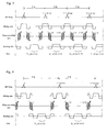
- Fig. 3 is an explanatory diagram showing a normal steady-state pulse sequence employed in the first embodiment.
- Fig. 4 is an explanatory diagram showing a steady-state pulse sequence devised in consideration of flow compensation and employed in the first embodiment.
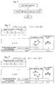
- Fig. 5 is a flowchart describing image construction employed in the first embodiment.
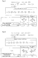
- Fig. 6 is an explanatory diagram conceptually expressing the principles of the first embodiment.
- Fig. 7 is an explanatory diagram conceptually expressing the principles of the second embodiment.
- Fig. 8 is a flowchart describing data acquisition employed in the third embodiment.
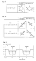
- Fig. 9 is an explanatory diagram indicating center and step.
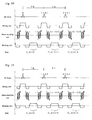
- Fig. 10 is an explanatory diagram showing a first steady-state pulse sequence employed in the third embodiment.
- Fig. 11 is an explanatory diagram showing a second steady-state pulse sequence employed in the third embodiment.
- Fig. 12 is a flowchart describing image construction employed in the third embodiment.
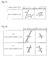
- Fig. 13 is a conceptual explanatory diagram showing the nature of data acquired according to the first steady-state pulse sequence employed in the third embodiment.
- Fig. 14 is a conceptual explanatory diagram showing the nature of data acquired according to the second steady-state pulse sequence employed in the third embodiment.
- Fig. 15 is a conceptual explanatory diagram showing rotation of the phases of echoes represented by the data acquired according to the second steady-state pulse sequence employed in the third embodiment.
- Fig. 16 is an explanatory diagram conceptually showing the principles of the third embodiment.
- Fig. 17 is a conceptual explanatory diagram showing the nature of data acquired according to a first steady-state pulse sequence employed in the fourth embodiment.
- Fig. 18 is a conceptual explanatory diagram showing the nature of data acquired according to a second steady-state pulse sequence employed in the fourth embodiment.
- Fig. 19 is a conceptual explanatory diagram showing rotation of the phases of echoes represented by the data acquired according to the second steady-state pulse sequence employed in the fourth embodiment.
- Fig. 20 is an explanatory diagram conceptually showing the principles of the fourth embodiment.
- Fig. 21 is a conceptual explanatory diagram showing the nature of data acquired according to a first steady-state pulse sequence employed in the fifth embodiment.
- Fig. 22 is a conceptual explanatory diagram showing the nature of data acquired according to a second steady-state pulse sequence employed in the fifth embodiment.
- Fig. 23 is a conceptual explanatory diagram showing rotation of the phases of echoes represented by the data acquired according to the second steady-state pulse sequence employed in the fifth embodiment.
- Fig. 24 is an explanatory diagram conceptually showing the principles of the fifth embodiment.
- Fig. 25 is a conceptual explanatory diagram showing the nature of data acquired according to a first steady-state pulse sequence employed in the sixth embodiment.
- Fig. 26 is a conceptual explanatory diagram showing the nature of data acquired according to a second steady-state pulse sequence employed in the sixth embodiment.
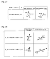
- Fig. 27 is a conceptual explanatory diagram showing rotation of the phases of echoes represented by the data acquired according to the second steady-state pulse sequence employed in the sixth embodiment.
- Fig. 28 is an explanatory diagram conceptually showing the principles of the sixth embodiment.
- Fig. 29 is an explanatory diagram showing a first steady-state pulse sequence employed in a related art.
- Fig. 30 is an explanatory diagram showing a second steady-state pulse sequence employed in the related art.
- Fig. 31 is a conceptual explanatory diagram showing the nature of data acquired according to the first steady-state pulse sequence employed in the related art.
- Fig. 32 is a conceptual explanatory diagram showing the nature of data acquired according to the second steady-state pulse sequence employed in the related art.
- Fig. 33 is a conceptual explanatory diagram showing rotation of the phases of echoes represented by the data acquired according to the second steady-state pulse sequence employed in the related art.
- Fig. 34 is an explanatory diagram conceptually showing the principles of the related art.
- Fig. 35 is an explanatory diagram expressing center and step employed in the related art.
-
- The present invention will be further described below by taking illustrated embodiments for instance. Noted is that the present invention will not be limited to the embodiments.
- Prior to description of embodiments, a conceptual model will be presented for explanation of the principles of the present invention.
- Data D_ acquired according to a steady-state pulse sequence specifying that the phase of an RF pulse is varied in order of 0×, 1×, 2×, 3×, etc. originates from an echo Ew induced by water and an echo Ef induced by fat. The echo Ew induced by water is a synthesis of a gradient echo GRE and a spin echo SE which are induced by water. The gradient echo component leads the spin echo component by -π. On the other hand, the echo Ef induced by fat is a synthesis of a gradient echo and a spin echo which are induced by fat. The gradient echo component leads the spin echo component by -π-fat. Herein, fat denotes a phase by which the spin echo component of an echo induced by water leads the spin echo component of an echo induced by water in a steady state due to chemical shifts. For generalization, the spin echo component shall lead the gradient echo component by -π-chem irrespective of whether they are the components of an echo induced by water or fat. For the spin echo component of an echo induced by water, chem shall be equal to 0. For the spin echo component of an echo induced by fat, chem shall be equal to fat.
- The foregoing conceptual model is adapted to data D_1 acquired according to a steady-state pulse sequence specifying 1=3π/2 as shown in Fig. 29. In this case, as shown in Fig. 31, the spin echo component of an echo Ew1 induced by water leads the gradient echo component thereof by π/2. As for an echo Ef1 induced by fat, the spin echo component of the echo leads the gradient echo component thereof by -π/2.
- Moreover, the foregoing conceptual model is adapted to data D_2 acquired according to a steady-state pulse sequence specifying 2=π/2 as shown in Fig. 30. In this case, as shown in Fig. 32, the spin echo component of an echo Ew2 induced by water leads the gradient echo thereof by -π/2. As for an echo Ef2 induced by fat, the spin echo component of the echo leads the gradient echo component thereof by -3π/2.
- As shown in Fig. 33, exp(i×π/2)×D_2 signifies that the echo Ew2 induced by water is rotated by π/2 in order to produce an echo Ew2' and that the echo Ef2 induced by fat is rotated by π/2 in order to produce an echo Ef2'.
- Consequently, as shown in Fig. 34, data processing expressed as Dw=D_1+exp(i×π/2)×D_2 signifies that the echo Ew1 induced by water and the echo Ew2' are added up and the echo Ef1 induced by fat and the echo Ef2' are added up. Eventually, after the addition is completed, the resultant echo Ew induced by water is enhanced and the resultant echo Ef induced by fat is suppressed.
- On the other hand, as shown in Fig. 34, data processing expressed as Df=D_1-exp(i×π/2)×D_2 signifies that the echo Ew2' is subtracted from the echo Ew1 induced by water and the echo Ef2' is subtracted from the echo Ef1 induced by fat. Eventually, after the subtraction is completed, the resultant echo Ew induced by water is suppressed and the resultant echo Ef induced by fat is enhanced.
- As mentioned above, according to the LCSSFP method, a water component-enhanced/fat component-suppressed image Gw can be constructed using data Dw and a fat component-enhanced/water component-suppressed image Gf can be constructed using data Df.
- Incidentally, Fig. 35 shows a change in a signal strength S in association with a change in a phase difference by which the spin echo component of an echo induced by fat leads the spin echo component of an echo induced by water.
- The phase difference associated with the center of the portion of a line graph indicating a decrease in the signal strength S shall be defined as a center phase center, and the center phase center is set to π. The width of the portion of the line graph indicating the decrease therein shall be defined as a phase width step, and the half of the phase width step is set to π/2. The relationships of center=(1+2)/2 and step=(1-2)/2 are established.
- Fig. 1 is a block diagram showing an MRI system 100 in accordance with the first embodiment.
- In the MRI system 100, a
magnet assembly 101 has a bore into which a subject is inserted. A static magnetic field coil 101C for applying a constant static magnetic field to the subject, gradient coils 101G for producing magnetic field gradients whose directions coincide with the directions of X, Y, and Z axes (that serve as a slicing axis, a phase-encoding axis, and a reading axis), a transmitter coil 101T for applying RF pulses for excitation of spins of nuclei in the subject's body, and a receiver coil 101R for detecting NMR signals induced by the subject. The static magnetic field coil 101C, gradient coils 101G, transmitter coil 101T, and receiver coil 101R are connected to a static magnetic field power supply 102, a gradient coil drive circuit 103, anRF power amplifier 104, and apreamplifier 105 respectively. - Incidentally, a permanent magnet may be substituted for the static magnetic field coil 101C.
- A
sequence memory circuit 8 activates the gradient coil drive circuit 103 according to a stored pulse sequence in response to a command issued from acomputer 107. This causes the gradient coils 101G included in themagnet assembly 101 to produce magnetic field gradients. Moreover, thesequence memory circuit 8 activates agate modulation circuit 9 for modulation of a carrier-wave output signal of an RFoscillatory circuit 15 into a pulsating signal that exhibits a predetermined timing, a predetermined envelope, and a predetermined phase. The pulsating signal is applied as RF pulses to theRF power amplifier 104. After the power of the RF pulses is amplified by theRF power amplifier 104, the RF pulses are applied to the transmitter coil 101T included in themagnet assembly 101. - The
preamplifier 105 amplifies NMR signals received from the subject by the receiver coil 101 R included in themagnet assembly 101, and transfers the resultant NMR signals to aphase detector 12. Thephase detector 12 detects the phases of the NMR signals sent from thepreamplifier 105 using the carrier-wave output signal of the RFoscillatory circuit 15 as a reference signal, and transfers the signals to an A/D converter 11. The A/D converter 11 converts the signals, which have the phases thereof detected, from an analog form to a digital form, and transfers the resultant signals to thecomputer 107. - The
computer 107 is responsible for overall control and receives information entered at an operator console 13. Moreover, thecomputer 107 reads digital data from the A/D converter 11, and performs computation on the digital data to construct an image. - An image and a message are displayed on a display device 106.
- Fig. 2 is a flowchart describing data acquisition employed in the first embodiment.
- At step A1, the
computer 107 determines a repetition time TR. For example, the options for the repetition time TR are displayed on the display device 106, and an operator is prompted to select any of the options. Herein, a magnetic field system shall offer a magnetic field strength of 0.2 T and the repetition time TR shall be set to 10 ms. - At step A2, fat is determined according to fat=(2-TR/T_out+2×m)×π where m denotes an integer equal to or larger than 0 and meets TR/(2×T_out)-1<m<TR/(2×T_out). Herein, T_out denotes the time during which spins in water and spins in fat are out of phase with each other due to chemical shifts.
- When the magnetic field system offers a magnetic field strength of 0.2 T, T_out is 20 ms. Therefore, if the repetition time TR is 10 ms, m equals 0 and fat equals 3π/2.
- At step A3, as shown in Fig. 3 or Fig. 4, data D_fat is acquired according to a steady-state pulse sequence specifying that the phase of an RF pulse is varied in order of 0, 1×fat, 2×fat, etc.
- Fig. 3 shows a normal steady-state pulse sequence, and Fig. 4 shows a steady-state pulse sequence determined in consideration of flow compensation.
- Thereafter, data acquisition is terminated.
- Fig. 5 is a flowchart describing image construction employed in the first embodiment.
- At step B1, the
computer 107 constructs an image Gw using data D_fat. - Then, image construction is terminated.
- Fig. 6 is an explanatory diagram concerning the aforesaid conceptual model adapted to the data D_fat acquired according to the steady-state pulse sequence specifying fat=3π/2 as shown in Fig. 3 or Fig. 4.
- The spin echo component of an echo Ew induced by water leads the gradient echo component thereof by π/2. The spin echo component of an echo Ef induced by fat leads the gradient echo component thereof by -π.
- Consequently, the echo Ew induced by water is enhanced but the echo Ef induced by fat is suppressed.
- Eventually, a water component-enhanced/fat component-suppressed image Gw can be constructed using the data D_fat.
- The second embodiment is fundamentally identical to the first embodiment. However, a magnetic field system shall offer a magnetic field strength of 1.5 T and the repetition time TR shall be set to 8.05 ms.
- In this case, as shown in Fig. 7, m equals 1 and fat equals π/2.
- The spin echo component of an echo Ew induced by water leads the gradient echo component thereof by -π/2. The spin echo component of an echo Ef induced by fat leads the gradient echo component thereof by -π.
- Consequently, the echo Ew induced by water is enhanced and the echo Ef induced by fat is suppressed.
- Eventually, a water component-enhanced/fat component-suppressed image Gw can be constructed using the data D_fat.
- Fig. 8 is a flowchart describing data acquisition employed in the third embodiment.
- At step C1, the
computer 107 determines the repetition time TR and step. For example, the options for the repetition time TR and the options for step are displayed on the display device 106, and an operator is prompted to select any of the options. step denotes a half of a phase width, that is, a half of the width of the portion of a line graph indicating a decrease in a signal strength S. Herein, the line graph expresses a change in the signal strength S in association with a change in a phase by which the spin echo component of an echo induced by water leads the spin echo component of an echo induced by fat. - Herein, a magnetic field system shall offer a magnetic field strength of 0.2 T, the repetition time TR shall be set to 10 ms, and step shall be set to π/4.
- At step C2, fat is determined according to fat=(2-TR/T_out+2×m)×π where m denotes an integer equal to or larger than 0 and meets TR/(2×T_out)-1<m<TR/(2×T_out). Herein, T_out denotes the time during which spins in water and spins in fat are out of phase with each other due to chemical shifts.
- Moreover, center is determined. center denotes, as shown in Fig. 9, a center phase, that is, a phase difference associated with the center of the portion of a line graph indicating a decrease in a signal strength S. Herein, the line graph expresses a change in the signal strength S in association with a change in a phase difference by which the spin echo component of an echo induced by fat leads the spin echo component of an echo induced by water.
- However, any of 0<center<π, -π<center<0, 0<step<π/2, and π/2<step<π shall be met.
- Herein, the magnetic field system shall offer a magnetic field strength of 0.2 T and T_out shall be 20 ms. Assuming that the repetition time TR is 10 ms, m equals 0 and fat equals 3π/2.
- Moreover, center=fat=3π/2 shall be established.
- At step C3, 1 and 2 are determined according to 1=center+step and 2=center-step respectively.
- Herein, since center equals 3π/2 and step equals π/4, 1 comes to 7π/4 and 2 comes to 5π/4.
- At step C4, as shown in Fig. 10, data D_1 is acquired according to a steady-state pulse sequence specifying that the phase of an RF pulse is varied in order of 0, 1×1, 2×1, etc. Incidentally, Fig. 10 shows a normal steady-state pulse sequence. A steady-state pulse sequence determined in consideration of flow compensation may be substituted for the normal steady-state pulse sequence.
- At step C5, as shown in Fig. 11, data D_2 is acquired according to a steady-state pulse sequence specifying that the phase of an RF pulse is varied in order of 0, 1×2, 2×2, etc. Incidentally, Fig. 11 shows a normal steady-state pulse sequence. A steady-state pulse sequence determined in consideration of flow compensation may be substituted for the normal steady-state pulse sequence.
- Data acquisition is then terminated.
- Fig. 12 is a flowchart describing image construction employed in the third embodiment.
- At step H1, the
computer 107 determines sum within the range of 0<sum<π. sum denotes a phase by which echoes represented by data D_2 are rotated. - Herein, sum=step=π/4 shall be established.
- At step H2, data Dw is produced according to Dw= D_1+exp(i×sum)×D_2.
- At step H3, an image Gw is constructed based on the data Dw.
- At step H4, data Df is produced according to Df=D_1-exp(i×sum)×D_2.
- At step H5, an image Gf is constructed based on the data Df.
- Image construction is then terminated.
- Fig. 13 is an explanatory diagram concerning the aforesaid conceptual model adapted to the data D_1 acquired according to the steady-state pulse sequence specifying 1=7π/4 as shown in Fig. 10.
- The spin echo component of an echo Ew1 induced by water leads the gradient echo component thereof by 3π/4. The spin echo component of an echo Ef1 induced by fat leads the gradient echo component thereof by -3π/4.
- Fig. 14 is an explanatory diagram concerning the aforesaid conceptual model adapted to the data D_2 acquired according to the steady-state pulse sequence specifying 2=5π/4 as shown in Fig. 11.
- The spin echo component of an echo Ew2 induced by water leads the gradient echo component thereof by π/4. The spin echo component of an echo Ef2 induced by fat leads the gradient echo component thereof by 3π/4.
- As shown in Fig. 15, exp(i×sum)×D_2 signifies that the echo Ew2 induced by water is rotated by sum in order to produce an echo Ew2', and the echo Ef2 induced by fat is rotated by sum in order to produce an echo Ef2'. In Fig. 15, sum shall equal π/4.
- Consequently, as shown in Fig. 16, data processing expressed as Dw=D_1+exp(i×sum)×D_2 signifies that the echo Ew1 induced by water and the echo Ew2' are added up and the echo Ef1 induced by fat and the echo Ef2' are added up. Eventually, after the addition is completed, the resultant echo Ew induced by water is enhanced, and the resultant echo Ef induced by fat is suppressed.
- On the other hand, data processing expressed as Df=D_1-exp(i×π/2)×D_2 signifies that the echo Ew2' is subtracted from the echo Ew1 induced by water and the echo Ef2' is subtracted from the echo Ef1 induced by fat. Eventually, after the subtraction is completed, the resultant echo Ew induced by water is suppressed and the resultant echo Ef induced by fat is enhanced.
- As mentioned above, the third embodiment can construct a water component-enhanced/fat component-suppressed image Gw using data Dw and construct a fat component-enhanced/water component-suppressed image Gf using data Df.
- The fourth embodiment is fundamentally identical to the third embodiment. step=π and center=fat shall be established. A magnetic field system shall offer a magnetic field strength of 1.5 T and a repetition time TR shall be set to 8.05 ms.
- In this case, as shown in Fig. 17 and Fig. 18, m equals 1 and fat equals π/2. Moreover, 1 comes to 3π and 2 comes to π/4.
- As shown in Fig. 17, the aforesaid conceptual model is adapted to data D_1 acquired according to a steady-state pulse sequence specifying 1=3π/4. The spin echo component of an echo Ew1 induced by water leads the gradient echo component thereof by -π/4. The spin echo component of an echo Ef1 induced by fat leads the gradient echo component thereof by -3π/4.
- As shown in Fig. 18, the aforesaid conceptual model is adapted to data D_2 acquired according to a steady-state pulse sequence specifying 2=π/4. The spin echo component of an echo Ew2 induced by water leads the gradient echo component thereof by -3π/4. The spin echo component of an echo Ef2 induced by fat leads the gradient echo component thereof by -5π/4.
- As shown in Fig. 19, exp(i×sum)×D_2 signifies that the echo Ew2 induced by water is rotated by sum in order to produce an echo Ew2'. The echo Ef2 induced by fat is rotated by sum in order to produce an echo Ef2'. In Fig. 19, sum=step=π/4 shall be established.
- As shown in Fig. 20, data processing expressed as Dw=D_1+ exp(i×sum)×D_2 signifies that the echo Ew1 induced by water and the echo Ew2' are added up and the echo Ef1 induced by fat and the echo Ef2' are added up. Consequently, after the addition is completed, the resultant echo Ew induced by water is enhanced and the resultant echo Ef induced by fat is suppressed.
- On the other hand, data processing expressed as Df=D_1-exp(i×π/2)×D_2 signifies that the echo Ew2' is subtracted from the echo Ew1 induced by water and the echo Ef2' is subtracted from the echo Ef1 induced by fat. Consequently, after the subtraction is completed, the resultant echo Ew induced by water is suppressed and the resultant echo Ef induced by fat is enhanced.
- As mentioned above, the fourth embodiment can construct a water component-enhanced/fat component-suppressed image Gw using the data Dw and a fat component-enhanced/water component-suppressed image Gf using the data Df.
- The fifth embodiment is fundamentally identical to the third embodiment. A magnetic field system shall offer a magnetic field strength of 0.2 T, a repetition time Tr shall be set to 10 ms, fat shall be set to π/2, and center shall be set to π+fat/2-step.
- In this case, as shown in Fig. 21 and Fig. 22, center equals 5π/4, 1 equals 7π/4, and 2 equals 3π/4.
- As shown in Fig. 21, the aforesaid conceptual model is adapted to data D_1 acquired according to a steady-state pulse sequence specifying 1=7π/4. The spin echo component of an echo Ew1 induced by water leads the gradient echo component thereof by 3π/4. The spin echo component of an echo Ef1 induced by fat leads the gradient echo component thereof by -3π/4.
- As shown in Fig. 22, the aforesaid conceptual model is adapted to data D_2 acquired according to a steady-state pulse sequence specifying 2=3π/4. The spin echo component of an echo Ew2 induced by water leads the gradient echo component thereof by -π/4. The spin echo component of an echo Ef2 induced by fat leads the gradient echo component thereof by -7π/4.
- As shown in Fig. 23, exp(i×sum)×D_2 signifies that the echo Ew2 induced by water is rotated by sum in order to produce an echo Ew2', and the echo Ef2 induced by fat is rotated by sum in order to produce an echo Ef2'. In Fig. 23, sum=step=π/2 shall be established.
- As shown in Fig. 24, data processing expressed as Dw=D_1+exp(i×sum)×D_2 signifies that the echo Ew1 induced by water and the echo Ew2' are added up and the echo Ef1 induced by fat and the echo Ef2' are added up. Consequently, after the addition is completed, the resultant echo Ew induced by water is enhanced and the resultant echo Ef induced by fat is suppressed.
- On the other hand, data processing expressed as Df=D_1-exp(i×π/2)×D_2 signifies that the echo Ew2' is subtracted from the echo Ew1 induced by water and the echo Ef2' is subtracted from the echo Ef1 induced by fat. Consequently, after the subtraction is completed, the resultant echo Ew induced by water is suppressed and the resultant echo Ef induced by fat is enhanced.
- As mentioned above, the fifth embodiment can construct a water component-enhanced/fat component-suppressed image Fw using data Dw and a fat component-enhanced/water component-suppressed image Gf using data Df.
- The sixth embodiment is fundamentally identical to the fourth embodiment. A magnetic field system shall offer a magnetic field strength of 1.5 T, a repetition time TR shall be set to 8.05 ms, fat shall be set to π/2, center shall be set to π, and step shall be set to 3π/4.
- In this case, as shown in Fig. 25 and Fig. 26, 1 equals 7π/4 and 2 equals π/4.
- As shown in Fig. 25, the aforesaid conceptual model is adapted to data D_1 acquired according to a steady-state pulse sequence specifying 1=7π/4. The spin echo component of an echo Ew1 induced by water leads the gradient echo component thereof by 3π/4. The spin echo component of an echo Ef1 induced by fat leads the gradient echo component thereof by π/4.
- As shown in Fig. 26, the aforesaid conceptual model is adapted to data D_2 acquired according to a steady-state pulse sequence specifying 2=π/4. The spin echo component of an echo Ew2 induced by water leads the gradient echo component thereof by -3π/4. The spin echo component of an echo Ef2 induced by fat leads the gradient echo component thereof by -5π/4.
- As shown in Fig. 27, exp(i×sum)×D_2 signifies that the echo Ew2 induced by water is rotated by sum in order to produce an echo Ew2', and the echo Ef2 induced by fat is rotated by sum in order to produce an echo Ef2'. In Fig. 27 sum=step=3π/4 shall be established.
- As shown in Fig. 28, data processing expressed as Dw=D_1+exp(i×sum)×D_2 signifies that the echo Ew1 induced by water and the echo Ew2' are added up and the echo Ef1 induced by fat and the echo Ef2' are added up. Consequently, after the addition is completed, the resultant echo Ew induced by water is enhanced and the resultant echo Ef induced by fat is suppressed.
- On the other hand, data processing expressed as Df=D_1-exp(i×π/2)×D_2 signifies that the echo Ew2' is subtracted from the echo Ew1 induced by water and the echo Ef2' is subtracted from the echo Ef1 induced by fat. Consequently, after the subtraction is completed, the resultant echo Ew induced by water is suppressed and the resultant echo Ef induced by fat is enhanced.
- As mentioned above, the sixth embodiment can construct a water component-enhanced/fat component-suppressed image Gw using data Dw and a fat component-enhanced/water component-suppressed image Gf using data Df.
Claims (10)
- An MR data acquisition method for acquiring data D_fat according to a steady-state pulse sequence specifying that the phase of an RF pulse is varied in order of 0, 1×fat, 2×fat, etc., wherein fat=(2-TR/T_out+2×m)×π is established on the assumption that m denotes an integer equal to or larger than 0 and meets TR/(2×T_out)-1<m<TR/(2×T_out) where TR denotes a repetition time and T_out denotes the time during which spins in water and spins in fat are out of phase with each other due to chemical shifts.
- An MR data acquisition method for acquiring data D_1 according to a steady-state pulse sequence specifying that the phase of an RF pulse is varied in order of 0, 1×1, 2×1, etc., and for acquiring data D_2 according to a steady-state pulse sequence specifying that the phase of an RF pulse is varied in order of 0, 1×2, 2×2, etc., wherein: 1=center+step and 2=center-step are established on the assumption that center denotes a center phase, that is, a phase difference associated with the center of the portion of a line graph indicating a decrease in a signal strength, and that a phase width, that is, the width of the portion of the line graph indicating the decrease in a signal strength is provided as 2×step (where any of 0<center<π, -π<center<0, 0<step<π/2, and π/2<step<π is met).
- An MR image construction method for constructing an MR image Gw using data D_fat acquired according to said MR data acquisition method set forth in Claim 1.
- An MR image construction method for constructing an MR image Gw using data Dw, wherein when data D_1 and data D_2 acquired according to said MR data acquisition method set forth in Claim 2 are synthesized with a phase value added to the data D_2 using sum defined as 0<sum<π, the data Dw is produced according to Dw=D_1+exp(i×sum)×D_2.
- An MRI system (100) comprising a data acquisition device that when fat=(2-TR/T_out+2×m)×π is established on the assumption that m denotes an integer equal to or larger than 0 and meets TR/(2×T_out)-1<m<TR/(2×T_out) where TR denotes a repetition time and T_out denotes the time during which spins in water and spins in fat are out of phase with each other due to chemical shifts, acquires data D_fat according to a steady-state pulse sequence specifying that the phase of an RF pulse is varied in order of 0, 1×fat, 2×fat, etc.
- An MRI system (100) comprising a data acquisition device that when 1=center+step and 2=center-step are established on the assumption that center denotes a center phase, that is, a phase difference associated with the center of the portion of a line graph indicating a decrease in a signal strength, and that a phase width, that is, the width of the portion of the line graph indicating the decrease in a signal strength is provided as 2×step (where any of 0<center<π, -π<center<0, 0<step<π/2, and π/2<step<π is met), acquires data D_1 according to a steady-state pulse sequence specifying that the phase of an RF pulse is varied in order of 0, 1×1, 2×1, etc., and acquires data D_2 according to a steady-state pulse sequence specifying that the phase of an RF pulse is varied in order of 0, 1×2, 2×2, etc.
- An MRI system (100) according to Claim 6, wherein when fat=(2-TR/T_out+2×m)×π is established on the assumption that m denotes an integer equal to or larger than 0 and meets TR/(2×T_out)-1<m<TR/(2×T_out) where TR denotes a repetition time and T_out denotes the time during which spins in water and spins in fat are out of phase with each other due to chemical shifts, center=fat is established under the condition of 0<step≤π/2-|π-fat|/2.
- An MRI system (100) according to Claim 6, wherein when fat=(2-TR/T_out+2×m)×π is established on the assumption that m denotes an integer equal to or larger than 0 and meets TR/(2×T_out)-1<m<TR/(2×T_out) where TR denotes a repetition time and T_out denotes the time during which spins in water and spins in fat are out of phase with each other due to chemical shifts, center=fat/2+step is established under the condition of fat/2≤step≤π-fat/2 as long as fat≤π is met, or center=π+fat/2-step is established under the condition of π-fat/2≤step≤fat/2 as long as fat≥π is met.
- An MRI system (100) according to Claim 6, wherein: when fat=(2-TR/T_out+2×m)×π is established on the assumption that m denotes an integer equal to or larger than 0 and meets TR/(2×T_out)-1<m<TR/(2×T_out) where TR denotes a repetition time and T_out denotes the time during which spins in water and spins in fat are out of phase with each other due to chemical shifts, center=π is established under the condition of π/2+|π-fat|/2≤step<π.
- An MRI system (100) according to Claim 7, wherein step=π/2=|π-fat|/2 is established.
Applications Claiming Priority (2)
| Application Number | Priority Date | Filing Date | Title |
|---|---|---|---|
| JP2004040695A JP3968353B2 (en) | 2004-02-18 | 2004-02-18 | MRI equipment |
| JP2004040695 | 2004-02-18 |
Publications (3)
| Publication Number | Publication Date |
|---|---|
| EP1566652A2 true EP1566652A2 (en) | 2005-08-24 |
| EP1566652A3 EP1566652A3 (en) | 2005-12-14 |
| EP1566652B1 EP1566652B1 (en) | 2009-10-14 |
Family
ID=34709084
Family Applications (1)
| Application Number | Title | Priority Date | Filing Date |
|---|---|---|---|
| EP05250408A Expired - Lifetime EP1566652B1 (en) | 2004-02-18 | 2005-01-26 | Method and system of acquiring MR data of fat tissue. corresponding MR image construction method and system |
Country Status (6)
| Country | Link |
|---|---|
| US (2) | US7365537B2 (en) |
| EP (1) | EP1566652B1 (en) |
| JP (1) | JP3968353B2 (en) |
| KR (1) | KR100622777B1 (en) |
| CN (1) | CN1657004A (en) |
| DE (1) | DE602005017085D1 (en) |
Cited By (2)
| Publication number | Priority date | Publication date | Assignee | Title |
|---|---|---|---|---|
| EP1666911A3 (en) * | 2004-10-27 | 2007-04-25 | GE Medical Systems Global Technology Company, LLC | Phase cycling method in SSFP pulse sequence and magnetic resonance imaging apparatus |
| DE102005049587A1 (en) * | 2005-10-17 | 2007-04-26 | Siemens Ag | Method for operating magnetic resonance equipment involves radiating high frequency excitation pulses into two different tissue types and reading echo signals and selecting timing of reading to control contrast of recorded image |
Families Citing this family (8)
| Publication number | Priority date | Publication date | Assignee | Title |
|---|---|---|---|---|
| JP3968353B2 (en) * | 2004-02-18 | 2007-08-29 | ジーイー・メディカル・システムズ・グローバル・テクノロジー・カンパニー・エルエルシー | MRI equipment |
| US7992085B2 (en) * | 2005-09-26 | 2011-08-02 | Microsoft Corporation | Lightweight reference user interface |
| US7557575B2 (en) * | 2006-04-04 | 2009-07-07 | Kabushiki Kaisha Toshiba | Magnetic resonance imaging apparatus and magnetic resonance imaging method |
| JP5072250B2 (en) * | 2006-04-04 | 2012-11-14 | 株式会社東芝 | Magnetic resonance imaging system |
| JP5329818B2 (en) * | 2007-03-26 | 2013-10-30 | 株式会社東芝 | Magnetic resonance imaging apparatus and imaging condition setting method in magnetic resonance imaging apparatus |
| JP5300279B2 (en) * | 2008-01-31 | 2013-09-25 | 株式会社東芝 | Magnetic resonance imaging system |
| DE102011005728B4 (en) * | 2011-03-17 | 2012-10-31 | Siemens Aktiengesellschaft | Distortion free determination of magnetic resonance data |
| US9442174B2 (en) * | 2012-10-11 | 2016-09-13 | Siemens Medical Solutions Usa, Inc. | Using single continuous pulses for manipulating water and fat signals in magnetic resonance imaging |
Citations (1)
| Publication number | Priority date | Publication date | Assignee | Title |
|---|---|---|---|---|
| JP2003052667A (en) | 2001-06-29 | 2003-02-25 | General Electric Co <Ge> | Magnetic resonance imaging system |
Family Cites Families (18)
| Publication number | Priority date | Publication date | Assignee | Title |
|---|---|---|---|---|
| JP2791091B2 (en) * | 1989-03-31 | 1998-08-27 | 株式会社日立製作所 | Inspection equipment using nuclear magnetic resonance |
| JP3157537B2 (en) | 1991-05-29 | 2001-04-16 | ジーイー横河メディカルシステム株式会社 | MR device |
| JP3051374B2 (en) * | 1998-07-21 | 2000-06-12 | ジーイー横河メディカルシステム株式会社 | Magnetic resonance imaging device |
| DE19836612C2 (en) * | 1998-08-12 | 2000-06-29 | Siemens Ag | Method for operating a magnetic resonance imaging device for separating water and fat signals |
| JP3353826B2 (en) * | 1999-06-24 | 2002-12-03 | ジーイー横河メディカルシステム株式会社 | Magnetic field inhomogeneity measurement device, phase correction device, and magnetic resonance imaging device |
| JP3454760B2 (en) * | 1999-10-22 | 2003-10-06 | ジーイー・メディカル・システムズ・グローバル・テクノロジー・カンパニー・エルエルシー | Phase distribution measuring method and apparatus, phase correcting method and apparatus, and magnetic resonance imaging apparatus |
| JP3510542B2 (en) * | 1999-10-22 | 2004-03-29 | ジーイー・メディカル・システムズ・グローバル・テクノロジー・カンパニー・エルエルシー | Phase distribution measuring method and apparatus, phase correcting method and apparatus, and magnetic resonance imaging apparatus |
| JP3534669B2 (en) * | 2000-01-27 | 2004-06-07 | ジーイー・メディカル・システムズ・グローバル・テクノロジー・カンパニー・エルエルシー | Magnetic resonance imaging device |
| JP3875479B2 (en) * | 2000-10-20 | 2007-01-31 | ジーイー・メディカル・システムズ・グローバル・テクノロジー・カンパニー・エルエルシー | Magnetic resonance imaging device |
| JP3858191B2 (en) * | 2000-10-31 | 2006-12-13 | ジーイー・メディカル・システムズ・グローバル・テクノロジー・カンパニー・エルエルシー | MRI equipment |
| JP3796426B2 (en) * | 2001-10-04 | 2006-07-12 | ジーイー・メディカル・システムズ・グローバル・テクノロジー・カンパニー・エルエルシー | Magnetic resonance imaging device |
| JP2003250775A (en) * | 2002-02-25 | 2003-09-09 | Ge Medical Systems Global Technology Co Llc | Mri apparatus and mra shooting method |
| US6608479B1 (en) * | 2002-05-15 | 2003-08-19 | General Electric Company | Method and system for MRI with lipid suppression |
| US7587231B2 (en) * | 2004-01-09 | 2009-09-08 | Toshiba America Mri, Inc. | Water fat separated magnetic resonance imaging method and system using steady-state free-precession |
| JP3968353B2 (en) | 2004-02-18 | 2007-08-29 | ジーイー・メディカル・システムズ・グローバル・テクノロジー・カンパニー・エルエルシー | MRI equipment |
| US7253620B1 (en) * | 2004-03-08 | 2007-08-07 | United States Of America, As Represented By The Secretary, Department Of Health And Human Services | Spectrally selective suppression with steady-state free precession |
| JP2006075380A (en) * | 2004-09-10 | 2006-03-23 | Ge Medical Systems Global Technology Co Llc | Method of generating mr image and mri apparatus |
| US7449884B1 (en) * | 2007-05-04 | 2008-11-11 | The Board Of Trustees Of The Leland Stanford Junior University | Enhanced spectral selectivity for steady-state free precession imaging |
-
2004
- 2004-02-18 JP JP2004040695A patent/JP3968353B2/en not_active Expired - Fee Related
-
2005
- 2005-01-26 DE DE602005017085T patent/DE602005017085D1/en not_active Expired - Lifetime
- 2005-01-26 EP EP05250408A patent/EP1566652B1/en not_active Expired - Lifetime
- 2005-02-01 US US11/049,485 patent/US7365537B2/en not_active Expired - Fee Related
- 2005-02-18 CN CN2005100095680A patent/CN1657004A/en active Pending
- 2005-02-18 KR KR1020050013642A patent/KR100622777B1/en not_active Expired - Fee Related
-
2008
- 2008-03-17 US US12/049,776 patent/US7564242B2/en not_active Expired - Fee Related
Patent Citations (1)
| Publication number | Priority date | Publication date | Assignee | Title |
|---|---|---|---|---|
| JP2003052667A (en) | 2001-06-29 | 2003-02-25 | General Electric Co <Ge> | Magnetic resonance imaging system |
Cited By (4)
| Publication number | Priority date | Publication date | Assignee | Title |
|---|---|---|---|---|
| EP1666911A3 (en) * | 2004-10-27 | 2007-04-25 | GE Medical Systems Global Technology Company, LLC | Phase cycling method in SSFP pulse sequence and magnetic resonance imaging apparatus |
| DE102005049587A1 (en) * | 2005-10-17 | 2007-04-26 | Siemens Ag | Method for operating magnetic resonance equipment involves radiating high frequency excitation pulses into two different tissue types and reading echo signals and selecting timing of reading to control contrast of recorded image |
| DE102005049587B4 (en) * | 2005-10-17 | 2007-10-04 | Siemens Ag | Method for operating a magnetic resonance system and magnetic resonance system |
| US7429861B2 (en) | 2005-10-17 | 2008-09-30 | Siemens Aktiengesellschaft | MR system and operating method therefor allowing selection of points in time of signal readout |
Also Published As
| Publication number | Publication date |
|---|---|
| US7564242B2 (en) | 2009-07-21 |
| US20050179432A1 (en) | 2005-08-18 |
| EP1566652A3 (en) | 2005-12-14 |
| JP2005230133A (en) | 2005-09-02 |
| KR20060042997A (en) | 2006-05-15 |
| US7365537B2 (en) | 2008-04-29 |
| EP1566652B1 (en) | 2009-10-14 |
| JP3968353B2 (en) | 2007-08-29 |
| KR100622777B1 (en) | 2006-09-19 |
| CN1657004A (en) | 2005-08-24 |
| DE602005017085D1 (en) | 2009-11-26 |
| US20080157763A1 (en) | 2008-07-03 |
Similar Documents
| Publication | Publication Date | Title |
|---|---|---|
| US7564242B2 (en) | MR data acquisition method, MR image construction method, and MRI system | |
| EP0543468B1 (en) | Magnetic resonance imaging method | |
| US8093895B2 (en) | Magnetic resonance imaging apparatus and magnetic resonance imaging method of controlling image contrast | |
| US7199583B2 (en) | MR image production method and MRI apparatus | |
| US20100148774A1 (en) | Magnetic resonance imaging apparatus and magnetic resonance imaging method | |
| US20020196019A1 (en) | MRI system | |
| US6483305B1 (en) | Magnetic resonance method for reducing residual magnetization and adjusting the amplitude of gradient pulses | |
| JP3796455B2 (en) | MRI equipment | |
| JP2000166898A (en) | Method of compensating for remanence in a magnetic resonance imaging system and magnetic resonance imaging system | |
| US5652513A (en) | Phase sensitive magnetic resonance technique with integrated gradient profile and continuous tunable flow | |
| US7323873B2 (en) | Phase error measuring method, MR imaging method, and MRI system | |
| US6559643B2 (en) | Magnetic resonance method and apparatus which measures residual magnetization from two or more orderly height reduce gradient pulses, of alternately inverted polarity, applied prior to the transmitting of rf pulses | |
| US4954779A (en) | Correction for eddy current caused phase degradation | |
| US5359289A (en) | Magnetic resonance device | |
| US5068610A (en) | Mri method and device for fast determination of the transverse relaxation time constant t2 | |
| US6285900B1 (en) | Method and device for generating a perfusion image of a body portion using magnetic resonance imaging | |
| EP0963560B1 (en) | Method and device for magnetic resonance imaging | |
| US7009395B2 (en) | Method for MRI with steady-state free precession pulse sequences | |
| WO2001063313A2 (en) | Mr imaging method, phase error measuring method and mri system | |
| EP0497402A1 (en) | Magnetic resonance imaging method and device for reducing image errors in a magnetic resonance image | |
| US20020050816A1 (en) | MR imaging method, phase error measuring method, and MRI apparatus | |
| US5276397A (en) | Gradient magnetic field irradiation method in nuclear magnetic resonance imaging (MRI) and MRI apparatus using said method | |
| US4950992A (en) | Magnetic resonance imaging system and method | |
| EP4711795A1 (en) | Correcting disturbing effects in spin-echo imaging |
Legal Events
| Date | Code | Title | Description |
|---|---|---|---|
| PUAI | Public reference made under article 153(3) epc to a published international application that has entered the european phase |
Free format text: ORIGINAL CODE: 0009012 |
|
| AK | Designated contracting states |
Kind code of ref document: A2 Designated state(s): AT BE BG CH CY CZ DE DK EE ES FI FR GB GR HU IE IS IT LI LT LU MC NL PL PT RO SE SI SK TR |
|
| AX | Request for extension of the european patent |
Extension state: AL BA HR LV MK YU |
|
| PUAL | Search report despatched |
Free format text: ORIGINAL CODE: 0009013 |
|
| RTI1 | Title (correction) |
Free format text: METHOD AND SYSTEM OF ACQUIRING MR DATA OF FAT TISSUE. CORRESPONDING MR IMAGE CONSTRUCTION METHOD AND SYSTEM |
|
| AK | Designated contracting states |
Kind code of ref document: A3 Designated state(s): AT BE BG CH CY CZ DE DK EE ES FI FR GB GR HU IE IS IT LI LT LU MC NL PL PT RO SE SI SK TR |
|
| AX | Request for extension of the european patent |
Extension state: AL BA HR LV MK YU |
|
| 17P | Request for examination filed |
Effective date: 20060614 |
|
| AKX | Designation fees paid |
Designated state(s): DE FR GB |
|
| 17Q | First examination report despatched |
Effective date: 20061006 |
|
| GRAP | Despatch of communication of intention to grant a patent |
Free format text: ORIGINAL CODE: EPIDOSNIGR1 |
|
| GRAS | Grant fee paid |
Free format text: ORIGINAL CODE: EPIDOSNIGR3 |
|
| GRAA | (expected) grant |
Free format text: ORIGINAL CODE: 0009210 |
|
| AK | Designated contracting states |
Kind code of ref document: B1 Designated state(s): DE FR GB |
|
| REG | Reference to a national code |
Ref country code: GB Ref legal event code: FG4D |
|
| REF | Corresponds to: |
Ref document number: 602005017085 Country of ref document: DE Date of ref document: 20091126 Kind code of ref document: P |
|
| PLBE | No opposition filed within time limit |
Free format text: ORIGINAL CODE: 0009261 |
|
| STAA | Information on the status of an ep patent application or granted ep patent |
Free format text: STATUS: NO OPPOSITION FILED WITHIN TIME LIMIT |
|
| 26N | No opposition filed |
Effective date: 20100715 |
|
| GBPC | Gb: european patent ceased through non-payment of renewal fee |
Effective date: 20100126 |
|
| REG | Reference to a national code |
Ref country code: FR Ref legal event code: ST Effective date: 20100930 |
|
| PG25 | Lapsed in a contracting state [announced via postgrant information from national office to epo] |
Ref country code: FR Free format text: LAPSE BECAUSE OF NON-PAYMENT OF DUE FEES Effective date: 20100201 |
|
| PG25 | Lapsed in a contracting state [announced via postgrant information from national office to epo] |
Ref country code: GB Free format text: LAPSE BECAUSE OF NON-PAYMENT OF DUE FEES Effective date: 20100126 |
|
| PGFP | Annual fee paid to national office [announced via postgrant information from national office to epo] |
Ref country code: DE Payment date: 20130129 Year of fee payment: 9 |
|
| REG | Reference to a national code |
Ref country code: DE Ref legal event code: R119 Ref document number: 602005017085 Country of ref document: DE |
|
| PG25 | Lapsed in a contracting state [announced via postgrant information from national office to epo] |
Ref country code: DE Free format text: LAPSE BECAUSE OF NON-PAYMENT OF DUE FEES Effective date: 20140801 |
|
| REG | Reference to a national code |
Ref country code: DE Ref legal event code: R119 Ref document number: 602005017085 Country of ref document: DE Effective date: 20140801 |