EP1566622A1 - Dispositif de répartition des liquides avec un adaptateur - Google Patents
Dispositif de répartition des liquides avec un adaptateur Download PDFInfo
- Publication number
- EP1566622A1 EP1566622A1 EP05102451A EP05102451A EP1566622A1 EP 1566622 A1 EP1566622 A1 EP 1566622A1 EP 05102451 A EP05102451 A EP 05102451A EP 05102451 A EP05102451 A EP 05102451A EP 1566622 A1 EP1566622 A1 EP 1566622A1
- Authority
- EP
- European Patent Office
- Prior art keywords
- fitting
- receiving
- fittings
- receiving element
- transfer line
- Prior art date
- Legal status (The legal status is an assumption and is not a legal conclusion. Google has not performed a legal analysis and makes no representation as to the accuracy of the status listed.)
- Withdrawn
Links
- 239000007788 liquid Substances 0.000 title claims abstract description 38
- 239000012530 fluid Substances 0.000 claims description 21
- 238000000926 separation method Methods 0.000 claims description 20
- 150000001875 compounds Chemical class 0.000 claims description 16
- 238000004811 liquid chromatography Methods 0.000 claims description 4
- 230000008878 coupling Effects 0.000 claims description 3
- 238000010168 coupling process Methods 0.000 claims description 3
- 238000005859 coupling reaction Methods 0.000 claims description 3
- 230000005484 gravity Effects 0.000 claims 1
- 238000005516 engineering process Methods 0.000 description 4
- 238000004128 high performance liquid chromatography Methods 0.000 description 3
- 238000004458 analytical method Methods 0.000 description 2
- 239000000969 carrier Substances 0.000 description 2
- 238000004587 chromatography analysis Methods 0.000 description 2
- 230000014759 maintenance of location Effects 0.000 description 2
- 239000000126 substance Substances 0.000 description 2
- 241000237970 Conus <genus> Species 0.000 description 1
- 230000015572 biosynthetic process Effects 0.000 description 1
- 230000006835 compression Effects 0.000 description 1
- 238000007906 compression Methods 0.000 description 1
- 230000001419 dependent effect Effects 0.000 description 1
- 239000013013 elastic material Substances 0.000 description 1
- 238000004949 mass spectrometry Methods 0.000 description 1
- 229920003023 plastic Polymers 0.000 description 1
- 239000004033 plastic Substances 0.000 description 1
- 238000002360 preparation method Methods 0.000 description 1
- 238000003786 synthesis reaction Methods 0.000 description 1
Images


Classifications
-
- G—PHYSICS
- G01—MEASURING; TESTING
- G01N—INVESTIGATING OR ANALYSING MATERIALS BY DETERMINING THEIR CHEMICAL OR PHYSICAL PROPERTIES
- G01N30/00—Investigating or analysing materials by separation into components using adsorption, absorption or similar phenomena or using ion-exchange, e.g. chromatography or field flow fractionation
- G01N30/02—Column chromatography
- G01N30/26—Conditioning of the fluid carrier; Flow patterns
- G01N30/38—Flow patterns
- G01N30/46—Flow patterns using more than one column
- G01N30/466—Flow patterns using more than one column with separation columns in parallel
-
- B—PERFORMING OPERATIONS; TRANSPORTING
- B01—PHYSICAL OR CHEMICAL PROCESSES OR APPARATUS IN GENERAL
- B01D—SEPARATION
- B01D15/00—Separating processes involving the treatment of liquids with solid sorbents; Apparatus therefor
- B01D15/08—Selective adsorption, e.g. chromatography
- B01D15/10—Selective adsorption, e.g. chromatography characterised by constructional or operational features
- B01D15/24—Selective adsorption, e.g. chromatography characterised by constructional or operational features relating to the treatment of the fractions to be distributed
- B01D15/247—Fraction collectors
-
- G—PHYSICS
- G01—MEASURING; TESTING
- G01N—INVESTIGATING OR ANALYSING MATERIALS BY DETERMINING THEIR CHEMICAL OR PHYSICAL PROPERTIES
- G01N1/00—Sampling; Preparing specimens for investigation
- G01N1/02—Devices for withdrawing samples
- G01N1/10—Devices for withdrawing samples in the liquid or fluent state
- G01N1/18—Devices for withdrawing samples in the liquid or fluent state with provision for splitting samples into portions
-
- G—PHYSICS
- G01—MEASURING; TESTING
- G01N—INVESTIGATING OR ANALYSING MATERIALS BY DETERMINING THEIR CHEMICAL OR PHYSICAL PROPERTIES
- G01N30/00—Investigating or analysing materials by separation into components using adsorption, absorption or similar phenomena or using ion-exchange, e.g. chromatography or field flow fractionation
- G01N30/02—Column chromatography
- G01N30/80—Fraction collectors
- G01N30/82—Automatic means therefor
-
- G—PHYSICS
- G01—MEASURING; TESTING
- G01N—INVESTIGATING OR ANALYSING MATERIALS BY DETERMINING THEIR CHEMICAL OR PHYSICAL PROPERTIES
- G01N30/00—Investigating or analysing materials by separation into components using adsorption, absorption or similar phenomena or using ion-exchange, e.g. chromatography or field flow fractionation
- G01N30/02—Column chromatography
- G01N30/62—Detectors specially adapted therefor
- G01N30/72—Mass spectrometers
- G01N30/7233—Mass spectrometers interfaced to liquid or supercritical fluid chromatograph
-
- G—PHYSICS
- G01—MEASURING; TESTING
- G01N—INVESTIGATING OR ANALYSING MATERIALS BY DETERMINING THEIR CHEMICAL OR PHYSICAL PROPERTIES
- G01N30/00—Investigating or analysing materials by separation into components using adsorption, absorption or similar phenomena or using ion-exchange, e.g. chromatography or field flow fractionation
- G01N30/02—Column chromatography
- G01N30/84—Preparation of the fraction to be distributed
Definitions
- the present invention relates to an apparatus for distributing liquids to one or more receiving elements.
- the field of laboratory technology comprises chemical, physical and/or biological analysis, separation, synthesis or preparation of substances, in particular of compounds or fractions of a liquid.
- Such laboratory technology may comprise liquid chromatography ("LC") using liquid chromatographic columns ("LC columns”).
- Components or fractions may be collected as they elute from LC columns and subjected to further analysis as for example, by mass spectrometry ("MS").
- MS mass spectrometry
- a fraction collecting apparatus is used.
- Such a fraction collector is adapted to collect the fractions or components within several collection vessels or containers.
- a fraction collector comprises a distributing device or distributor adapted for distributing the respective fractions or compounds to the vessels or containers.
- An example of a fraction collecting system is disclosed in US 2002/0121468 A1.
- the objective indicated are achieved by providing the apparatus with an adapter, said adapter is adapted for transferring liquids from first receiving elements to second receiving elements.
- the first receiving elements are arranged within a first element arrangement.
- the second receiving elements are arranged in a second element arrangement.
- the apparatus also comprises a distributor adapted for distributing liquids to the first receiving elements. Since such a distributor is limited in distributing the liquids only to the first receiving elements, the size of such first receiving elements is restricted. If the first receiving elements are designed as containers, such containers will have only very small collecting capacities, for example in the range of several milliliters. With help of the adapter the first receiving elements are coupled to the second receiving elements which do not depend on the restrictions of the distributor.
- the second receiving elements can be provided with larger collecting capacities than the first receiving elements, e.g. in the range of centiliters, when the second receiving elements are designed as containers or vessels.
- the collecting of larger quantities of liquid, for example fractions or compounds is provided.
- the adapter comprises a fitting arrangement having one or more fittings.
- at least one of said fittings is adapted for aligning a transfer line to an opening of a single second receiving element.
- at least one of said transfer lines is adapted to transfer a liquid from a single first receiving element to a single second receiving element.
- another embodiment comprises for each pair of first receiving element and second receiving element a transfer line and a fitting. Consequently, the adapter provides an appropriate correlation between the first and second receiving elements.
- the adapter may comprise a fitting support adapted for supporting the fittings of the fitting arrangement.
- Said fitting support preferably comprises a fixed plate adapted for receiving the fittings and a moveable plate adapted for securing the fittings to the fitting support.
- the fixed plate may contain one or more receiving openings each adapted for receiving a single fitting, wherein said receiving openings and said fittings preferably are adapted for becoming adjusted into a predetermined position .
- Said predetermined positions are arranged relative to the second element arrangement in order to optimize the alignment of the transfer lines to the openings of the second receiving elements, said alignment being achieved by shape of the fittings.
- the moveable plate may contain one or more locking openings each adapted for receiving a single fitting, wherein the locking openings and the fittings preferably are adapted to establish a form-fit locking between the moveable plate and the fittings.
- the fittings are secured to the fitting support and cannot be extracted by mistake. Therefore, the fitting support improves the reliability of the apparatus.
- Embodiments also relate to a fluid separation system adapted for separating compounds of a fluid.
- Said system comprises the aforementioned apparatus and at least a fluid providing unit and a separation unit adapted for separating compounds of the fluid and an arrangement of at least one separation column. Since the apparatus allows the collecting of large quantities of separated fluids or liquids the field of application of such a system can be expanded.
- Fig. 1 depicts a simplified schematic view of a fluid separation system, according to embodiments of the invention
- Fig. 2 depicts a perspective view of an apparatus according to embodiments of the invention
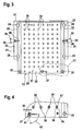
- Fig. 3 depicts a top view of a mid-level platform of the apparatus
- Fig. 4 depicts an enlarged detail IV of Fig. 3,
- Fig. 5 depicts a top view of a fitting support of the apparatus
- Fig. 6 depicts a cross section according to section lines VI in Fig. 5,
- Fig. 7 depicts an enlarged detail VII in Fig. 6,
- Fig. 8 depicts a simplified cross section of a first receiving element of the apparatus.
- a fluid separation system 1 comprises a distributing apparatus 2 and at least one of a fluid provider 3, a separation unit 4 and a column arrangement 5.
- the system 1 in general is adapted for separating compounds of a fluid and is usually used in the field of laboratory fluid processing, in particular for analytical or preparative purposes.
- the fluid provider 3 is adapted for providing the respective fluid, which is preferably a liquid but also may be a gas.
- the fluid provider 3 may comprise a nano-pump in particular a nano-pump disclosed in US 6,627,075 B1, which is incorporated herein by reference.
- the provider 3 is coupled to the apparatus 2 and to the column arrangement 5.
- the separation unit 4 is adapted for separating compounds of the fluid.
- the separation unit 4 comprises or is a chromatography system, in particular a liquid chromatography system.
- HPLC high performance liquid chromatography systems
- HPLC is a form of chromatography used to separate compounds, that are dissolved in liquid.
- the separation unit 4 is coupled to the apparatus 2.
- the column arrangement 5 comprises at least one separation column 6.
- separation columns 6 usually are adapted for providing a compound specific retention , i.e. such a separation column 6 is provided different retentions different compounds.
- the separation column 6 provides a compound specific retardation within a liquid flowing through the separation column 6, said retardation results in a separation of the different compounds.
- the liquid flowing out of the separation column 6 contains the separated compounds consecutively such that portions of the liquid containing the respective compounds be separated.
- the column arrangement 5 is coupled to the apparatus 2.
- Each of said couplings is symbolized by a double-arrow.
- the apparatus 2 is adapted for distributing liquids to one or more or preferably to several receiving elements 7, 8.
- the apparatus 8 comprises a first element arrangement 9, comprising one or more or preferably several first receiving elements 7.
- the distributor 11 preferably is adapted for supporting the first element arrangement.
- the apparatus 2 also comprises a second element arrangement 10 comprising one or more or preferably several second receiving elements 8. Further the apparatus 2 comprises a distributor 11 adapted for distributing liquids to the first receiving elements 7. Such a distributor 11 may be of the type of Fraction Collector of the Agilent 1100 Series G1364A by the applicant Agilent Technologies.
- the apparatus 2 furthermore is provided with an adapter 12.
- Said adapter 12 is adapted for transferring the liquids from the first receiving elements 7 to the second receiving elements 8.
- the apparatus 2 preferably is designed as a fraction collector.
- a fraction collector is adapted for analytical and/or preparative handling fluid fraction.
- Such a fraction collector is preferably used in the field of liquid chromatography.
- the first element arrangement 9 comprises in a preferred embodiment at least one first positioning cage 13.
- the first element arrangement 9 comprises two first positioning cages 13.
- Each first positioning cage 13 is adapted for positioning one or more or in particular several first receiving elements 7 in fact in predetermined positions relative to each other.
- the first receiving elements 7 may be designed as first containers or first vessels adapted for collecting a liquid. In such an embodiment said first containers have a relative small collection capacity, e.g. in the range of several milliliters.
- the second element arrangement 10 preferably comprises at least one second positioning cage 14.
- the second element arrangement 10 comprises four second positioning cages 14.
- Each second positioning cage 14 is adapted for positioning one or more or preferably several second receiving elements 8 in fact in predetermined positions relative to each other.
- the second receiving elements 8 preferably are designed as second containers or vessels adapted for collecting a liquid.
- the second receiving elements 8 are designed as test-tubes.
- the second receiving elements 8 or second containers, respectively have larger collecting capacities than the first receiving elements 7 or first containers, respectively.
- the second containers have collecting capacities in the range of centiliters.
- each first receiving element 7 is assigned to a single second receiving element 8 and vice versa. That means, that the number of first receiving elements 7 is equal to the number of the second receiving elements 8, and that every single first receiving element 7 has one corresponding second receiving element 8. Accordingly, the adapter 12 is adapted for transferring the liquids from every first receiving element 7 to each respective second receiving element 8.
- the apparatus 2 is also provided with a rack 15.
- Said rack 15 is adapted for supporting the distributor 11, the adapter 12 and the second element arrangement 10.
- the rack 15 comprises in the preferred embodiment according to figs. 1 and 2 a upper-level platform 16, a mid-level platform 17 and a low-level platform 18.
- the upper-level platform 16 is adapted for supporting the distributor 11.
- the mid-level platform 17 is adapted for supporting the adapter 12 and the low-level platform 18 is adapted for supporting the second element arrangement 10.
- the low-level platform 18 is also designed as a base plate adapted for supporting the whole rack 15.
- the rack 15 comprises also several rods 19 supported by the low-level platform 18 and supporting the upper-level platform 16.
- the mid-level platform 17 is attached to the rods 19 between the low-level platform 18 and the upper-level platform 16.
- the rack 15 preferably is adapted for adjusting the level of the mid-level platform 17 relative to the low-level platform 18 and the upper-level platform 16.
- the mid-level platform 17 is provided with an adjustment device 20.
- That adjustment device 20 comprises in the shown embodiment a clamping bar 21 which is slideably arranged within a slot 22 of a carrier 23.
- Said carrier 23 is provided with at least one through hole 24, through which one of the rods 19 extends. Each of this through holes 24 is open to the slot 22.
- the adjusting device 22 also comprises a fixation screw 25.
- Said fixation screw 25 is rotateably supported at the clamping bar 21, penetrates the clamping bar 21 and extends into a thread hole 26 (see fig. 3).
- Said thread hole 26 is provided at the carrier 23 and is open to the slot 22. Tightening of the fixation screw 25 forces the clamping bar 21 into the slot 22 and against the rod 19. Accordingly, the respective rod 19 is clamped within the respective through hole 24 between the carrier 23 and the clamping bar 21.
- the adjusting device 20 comprises in the depicted embodiment to arrangements of carrier 23, clamping bar 21 and fixation screw 25, each arrangement assigned to a side of the rack 15 provided with at least one rod 19.
- the adapter 12 comprises a fitting arrangement 27 comprising one or more or preferably several fittings 28. In the figs. 3 and 4 the fittings 28 are not shown.
- the adapter 12 also comprises a fitting support 29 adapted for supporting the fitting arrangement 27 or the fittings 28 of the fitting arrangement 27, respectively.
- Said fitting support 29 comprises a fixed plate 30 and a moveable plate 31, see figs. 6 and 7.
- the fixed plate 30 is adapted for receiving the fittings 28 and is supported by the mid-level platform 17. To this end the fixed plate 30 is at two opposing edges inserted into receiving slots 32 provided at the carriers 23 of the adjustment device 20.
- the fixed plate 30 is secured to said carriers 23 by means of clamping screws 33. The tightened clamping screws 33 press the fixed plate 30 against the carrier 23 within the receiving slot 32.
- the fixed plate 30 contains or more or preferably several receiving openings 34 each adapted for receiving a single fitting 28. In order to adjust a predetermined relative position of the respective fittings 28 the receiving openings 34 and the fittings 28 interact accordingly.
- the receiving openings 34 are adapted to the second element arrangement and define said predetermined relative positions of the fittings 28.
- the moveable plate 31 is moveably attached to the fixed plate 30.
- the moveable plate 31 is adapted to perform movements, preferably translatory movements, relative to the fixed plate 30. Said movements are symbolized in fig. 7 by means of a double-arrow 35.
- the moveable plate 31 is adapted for securing the fittings 28 to the fitting support 29.
- the moveable plate 31 contains one or more or preferably several locking openings 36 each adapted for receiving a single fitting 28.
- Said form-fit locking is preferably adapted to prevent extracting of the fittings 28 from the fitting support 29 or out of the locking openings 36 and the receiving openings 34, respectively.
- the moveable plate 31 is arranged underneath the fixed plate 30. It should be clear, that in another embodiment the fixed plate 30 could be arranged underneath the moveable plate 31.
- the fitting support 29 comprises at least one excenter drive 37.
- Said excenter drive 37 is adapted for providing said movement 35 of the moveable plate 31 relative to the fixed plate 30.
- the excenter drive 37 is pivotably supported at the one of the plates, here at the fixed plate 30.
- the excenter drive 37 comprises a cylinder 38 inserted into a bearing opening 39, which is provided at the fixed plate 30.
- Said cylinder 38 is coupled with a lever 40 adapted for providing a handling of the excenter drive 37.
- the cylinder 38 is pivotably seated within the bearing opening 39 with respect to a rotation axis 41.
- the excenter drive 37 or its cylinder 38, respectively, is also provided within an excenter pin 42 extending into a drive slot 43 provided at the other of the plates, here at the moveable plate 31.
- the excenter pin 42 is arranged eccentrically with respect to the rotation axis 41.
- An eccentricity 44 between the rotation axis 41 and the excenter pin 42 is depicted in fig. 4.
- the excenter drive 37 is adjustable between a release position and a locking position.
- the excenter drive 37 is adjusted in its locking position.
- Said locking position is adapted for securing the inserted fittings 38 to the fitting support 29.
- the cylinder 38 has to be turned around the rotation axis 41 by a predetermined angle 45.
- Said angle 45 is for example 90°.
- the release position is adapted for inserting and extracting the fittings 28 into or from the fitting support 29.
- the locking openings 36 preferably are provided with a cross-section having the shape of a key hole or a wedge or a triangle. According to fig. 4 said cross-section has a release portion 46 having at least the diameter of the respective receiving opening 34. In the release position the receiving openings 34 are aligned to the receiving portions 46 of the respective locking openings 36. Accordingly the fittings 28 can be inserted or extracted, respectively.
- each locking opening 36 also has a locking portion 47 characterized by a reduced diameter. In the locking position the receiving openings 34 are aligned to the locking portions 47 of the respective locking openings 36.
- each fitting 28 is provided with a locking portion 48 adapted for interacting with the respective locking opening 26.
- Said locking portion 48 of the fitting 28 is characterized by a cross-section, which is smaller than the cross-section of adjacent portions of the fitting 28 on both sides of the locking portion 48. Accordingly, the locking portion 47 of the locking opening 36 engages with the locking portion 48 of the fitting 28, when the moveable plate 31 is adjusted in the locking position.
- the fittings 28 are also provided with a positioning portion 49 adapted for interacting with the respective receiving opening 34.
- the receiving opening 34 and the receiving portions 49 have approximately the same diameter and are preferably adapted for providing only a small clearance.
- the fittings 28 are adapted for aligning a transfer line 50 with respect to an opening 51 (see figs. 1 and 2) of a single second receiving element 8.
- Said transfer line 50 is, for example, provided by means of flexible hose or tube.
- Each transfer line 50 is coupled to a single first receiving element 7.
- each fitting 28 is assigned to a single first receiving element 7 and to a single second receiving element 8.
- Said transfer line 50 is adapted to transfer a liquid from a single first receiving element 7 to a single second receiving element 8.
- Each fitting 28 comprises an insert member 52 and an alignment member 53.
- the insert member 52 is adapted for inserting the transfer line 50 into the fitting 28.
- the insert member 52 is provided with a funneled insert opening 54 and a center bore 55.
- the alignment member 53 is adapted for aligning the transfer line 50 to the opening 51 of the respective second receiving element 8.
- the alignment member 53 is provided with a center bore 56 aligned to the center bore 55 of the insert member 52.
- the transfer line 50 extends out of the alignment member 53 and ends approximately at the level of the respective opening 51.
- the insert member 52 and the alignment member 53 are joint together for example by means of a thread connection 57.
- Insert member 52 and alignment member 53 are adapted for interacting in order to fix the transfer line 50 to the respective fitting 28.
- at least one fixing member 58 is axially arranged between a portion of the insert member 52 and a portion of the alignment member 53.
- Said fixing member 58 encloses the transfer line 50 and is made of an elastic material, for example plastics or synthetics.
- the fixing member 58 is a O-ring seal.
- Said fixing member 58 is axially compressed, when the insert member 52 is joined to the alignment member 53. As a result of said axial compression the fixing member 58 extends radially and accordingly compresses the transfer line 50 in order to establish a suitable fixation of the transfer line 50 to the fitting 28.
- At least one of the first receiving elements 7 comprises in a preferred embodiment an inlet port 59.
- the distributor 11 is provided with an outlet port 60 which is moveable vertically (see arrow 61) and horizontally (see arrow 62) in order to distribute the liquid to the different first receiving elements 7 of the first element arrangement 9.
- the inlet port 59 is adapted for interacting with the outlet port 60, for example the inlet port 59 and/or the outlet port 60 has/have a conus shape. Accordingly, the inlet port 59 defines a seating for the outlet port 60, said seating establishes a pressure tight coupling between inlet port 59 and outlet port 60. Accordingly, the distributor 11 may be adapted for injecting the respective liquid pressurized out of its outlet port 60 and therefore into the inlet port 59 and thus into the respective first receiving element 7.
- the inlet port 59 is coupled to a connecting sleeve 63.
- Said connecting sleeve 63 is coupled to the transfer line 50.
- the adapter 12 allows collecting of larger quantities of liquids by using a conventional distributor 11 adapted for distributing the liquids to the first receiving elements 7 provided with small collecting capacities, since the adapter 12 transfers the liquids from the first receiving elements 7 to the larger second receiving elements 8.
Landscapes
- Chemical & Material Sciences (AREA)
- Analytical Chemistry (AREA)
- Life Sciences & Earth Sciences (AREA)
- General Health & Medical Sciences (AREA)
- Health & Medical Sciences (AREA)
- Biochemistry (AREA)
- Physics & Mathematics (AREA)
- General Physics & Mathematics (AREA)
- Immunology (AREA)
- Pathology (AREA)
- Chemical Kinetics & Catalysis (AREA)
- Hydrology & Water Resources (AREA)
- Feeding, Discharge, Calcimining, Fusing, And Gas-Generation Devices (AREA)
- Treatment Of Liquids With Adsorbents In General (AREA)
Priority Applications (2)
| Application Number | Priority Date | Filing Date | Title |
|---|---|---|---|
| EP05102451A EP1566622A1 (fr) | 2005-03-29 | 2005-03-29 | Dispositif de répartition des liquides avec un adaptateur |
| US11/207,217 US7491326B2 (en) | 2005-03-29 | 2005-08-19 | Apparatus for distributing liquids having an adapter |
Applications Claiming Priority (1)
| Application Number | Priority Date | Filing Date | Title |
|---|---|---|---|
| EP05102451A EP1566622A1 (fr) | 2005-03-29 | 2005-03-29 | Dispositif de répartition des liquides avec un adaptateur |
Publications (1)
| Publication Number | Publication Date |
|---|---|
| EP1566622A1 true EP1566622A1 (fr) | 2005-08-24 |
Family
ID=34707432
Family Applications (1)
| Application Number | Title | Priority Date | Filing Date |
|---|---|---|---|
| EP05102451A Withdrawn EP1566622A1 (fr) | 2005-03-29 | 2005-03-29 | Dispositif de répartition des liquides avec un adaptateur |
Country Status (2)
| Country | Link |
|---|---|
| US (1) | US7491326B2 (fr) |
| EP (1) | EP1566622A1 (fr) |
Cited By (1)
| Publication number | Priority date | Publication date | Assignee | Title |
|---|---|---|---|---|
| WO2021191730A1 (fr) * | 2020-03-27 | 2021-09-30 | Agilent Technologies, Inc. | Alimentation en solvant de chromatographie muni d'un bras de colonne de production permettant le positionnement d'une extrémité de colonne de production |
Families Citing this family (4)
| Publication number | Priority date | Publication date | Assignee | Title |
|---|---|---|---|---|
| EP1889526B1 (fr) * | 2005-05-23 | 2010-01-20 | Agilent Technologies, Inc. | Plaque de support pour un dispositif |
| US20090121476A1 (en) * | 2007-11-08 | 2009-05-14 | The Government Of The Us, As Represented By The Secretary Of The Navy | Microfluidic Bus for Interconnecting Multiple Fluid Conduits |
| US8037788B2 (en) * | 2008-07-24 | 2011-10-18 | Dionex Corporation | Tight-spot fitting and driver, and method of use thereof |
| US8960319B2 (en) * | 2010-07-28 | 2015-02-24 | The Viking Corporation | Flat plate concealed horizontal sidewall sprinkler |
Citations (6)
| Publication number | Priority date | Publication date | Assignee | Title |
|---|---|---|---|---|
| GB995016A (en) * | 1961-08-07 | 1965-06-10 | Ceskoslovenska Akademie Ved | Apparatus for the distribution of fluid in successive portions |
| US3765461A (en) * | 1972-03-03 | 1973-10-16 | K Keck | Apparatus for transferring separate liquid fractions into separate fraction vessels |
| US4049031A (en) * | 1975-12-22 | 1977-09-20 | Smithkline Corporation | Automatic fraction collector |
| US20020121468A1 (en) * | 2000-07-06 | 2002-09-05 | Fischer Steven M. | Fraction collection delay calibration for liquid chromatography |
| US20040096986A1 (en) * | 2002-11-13 | 2004-05-20 | Klein Kenneth J. | Pharmaceutical combi-chem purification factory system |
| US20040237672A1 (en) * | 2003-04-30 | 2004-12-02 | Jaeger Ben E. | Sampling apparatus having a linear indexing sample collection station |
Family Cites Families (6)
| Publication number | Priority date | Publication date | Assignee | Title |
|---|---|---|---|---|
| DE19704477A1 (de) * | 1997-02-06 | 1998-08-13 | Solvay Pharm Gmbh | Vorrichtung und Verfahren zur Parallel-Chromatographie |
| DE19914358C2 (de) * | 1999-03-30 | 2001-05-17 | Agilent Technologies Inc | Vorrichtung und Verfahren zur Bereitstellung von Volumenströmen von Flüssigkeiten in Kapillaren |
| US6106710A (en) * | 1999-09-10 | 2000-08-22 | Agilent Technologies, Inc. | Fraction collection delay calibration for liquid chromatography |
| US6355164B1 (en) * | 1999-10-29 | 2002-03-12 | Ontogen Corporation | Sample collection apparatus and method for multiple channel high throughput purification |
| JP4615101B2 (ja) * | 2000-08-08 | 2011-01-19 | 昭光サイエンティフィック株式会社 | 精製分取装置 |
| US6936167B2 (en) * | 2002-10-31 | 2005-08-30 | Nanostream, Inc. | System and method for performing multiple parallel chromatographic separations |
-
2005
- 2005-03-29 EP EP05102451A patent/EP1566622A1/fr not_active Withdrawn
- 2005-08-19 US US11/207,217 patent/US7491326B2/en not_active Expired - Fee Related
Patent Citations (6)
| Publication number | Priority date | Publication date | Assignee | Title |
|---|---|---|---|---|
| GB995016A (en) * | 1961-08-07 | 1965-06-10 | Ceskoslovenska Akademie Ved | Apparatus for the distribution of fluid in successive portions |
| US3765461A (en) * | 1972-03-03 | 1973-10-16 | K Keck | Apparatus for transferring separate liquid fractions into separate fraction vessels |
| US4049031A (en) * | 1975-12-22 | 1977-09-20 | Smithkline Corporation | Automatic fraction collector |
| US20020121468A1 (en) * | 2000-07-06 | 2002-09-05 | Fischer Steven M. | Fraction collection delay calibration for liquid chromatography |
| US20040096986A1 (en) * | 2002-11-13 | 2004-05-20 | Klein Kenneth J. | Pharmaceutical combi-chem purification factory system |
| US20040237672A1 (en) * | 2003-04-30 | 2004-12-02 | Jaeger Ben E. | Sampling apparatus having a linear indexing sample collection station |
Cited By (1)
| Publication number | Priority date | Publication date | Assignee | Title |
|---|---|---|---|---|
| WO2021191730A1 (fr) * | 2020-03-27 | 2021-09-30 | Agilent Technologies, Inc. | Alimentation en solvant de chromatographie muni d'un bras de colonne de production permettant le positionnement d'une extrémité de colonne de production |
Also Published As
| Publication number | Publication date |
|---|---|
| US7491326B2 (en) | 2009-02-17 |
| US20060219617A1 (en) | 2006-10-05 |
Similar Documents
| Publication | Publication Date | Title |
|---|---|---|
| US20170023536A1 (en) | Modular Multiple-Column Chromatography Cartridge | |
| US6171486B1 (en) | Liquid chromatography column | |
| US7491326B2 (en) | Apparatus for distributing liquids having an adapter | |
| EP1113849B1 (fr) | Module et procede d'introduction d'un echantillon dans une colonne de chromatographie | |
| Kataoka | New trends in sample preparation for clinical and pharmaceutical analysis | |
| EP2633304B1 (fr) | Appareil et procédé permettant de coupler un tube à une colonne de chromatographie | |
| DE112005002008B4 (de) | Vorrichtung und Apparatur zum Durchführen von Trennungen | |
| US5472598A (en) | Connection assembly for liquid chromatography columns | |
| US6319476B1 (en) | Microfluidic connector | |
| US6723236B2 (en) | Device for solid phase extraction and method for purifying samples prior to analysis | |
| US20100224543A1 (en) | Connection assembly for ultra high pressure liquid chromatography | |
| DK163801B (da) | For-kolonne til brug ved kromatografi og apparat til brug i et system til vaeskekromatografering | |
| US20070102358A1 (en) | Solid phase extraction column | |
| CN104105963B (zh) | 用于将毛细管连接到流体组件的流体导管的快锁连接器 | |
| WO2014085417A1 (fr) | Interconnexion micro-fluidique | |
| CN111837032A (zh) | 样品处理和分配各个样品包 | |
| CN114100197A (zh) | 具有穿入到针开口中的导管末端的样品注入器 | |
| CN114814048A (zh) | 通过旋转机构安装样品分离单元 | |
| Lee et al. | Evaluation of multiplexed hollow fiber flow field-flow fractionation for semi-preparative purposes | |
| Campíns‐Falcó et al. | Solid‐phase extraction and clean‐up procedures in pharmaceutical analysis | |
| WO2006044441A2 (fr) | Dispositifs de traitement de liquides equipes de multiples mecanismes d'etancheite, et procedes automatises d'exploitation des dispositifs | |
| CN211086205U (zh) | 一种多维在线固相萃取液相色谱装置 | |
| US20230210420A1 (en) | Sampling with fitting between needle and housing | |
| WO2022072213A1 (fr) | Colonne de chromatographie | |
| WO2020142753A1 (fr) | Système d'adaptateur de cartouche de chromatographie pouvant être échangé |
Legal Events
| Date | Code | Title | Description |
|---|---|---|---|
| PUAI | Public reference made under article 153(3) epc to a published international application that has entered the european phase |
Free format text: ORIGINAL CODE: 0009012 |
|
| 17P | Request for examination filed |
Effective date: 20050604 |
|
| AK | Designated contracting states |
Kind code of ref document: A1 Designated state(s): AT BE BG CH CY CZ DE DK EE ES FI FR GB GR HU IE IS IT LI LT LU MC NL PL PT RO SE SI SK TR |
|
| AX | Request for extension of the european patent |
Extension state: AL BA HR LV MK YU |
|
| AKX | Designation fees paid |
Designated state(s): DE FR GB |
|
| RAP1 | Party data changed (applicant data changed or rights of an application transferred) |
Owner name: AGILENT TECHNOLOGIES, INC. |
|
| 17Q | First examination report despatched |
Effective date: 20080521 |
|
| STAA | Information on the status of an ep patent application or granted ep patent |
Free format text: STATUS: THE APPLICATION IS DEEMED TO BE WITHDRAWN |
|
| 18D | Application deemed to be withdrawn |
Effective date: 20091001 |