EP1566603A1 - Method for assembling a reinforcement onto the faceplate of a refrigerator, freezer or the like - Google Patents
Method for assembling a reinforcement onto the faceplate of a refrigerator, freezer or the like Download PDFInfo
- Publication number
- EP1566603A1 EP1566603A1 EP05100220A EP05100220A EP1566603A1 EP 1566603 A1 EP1566603 A1 EP 1566603A1 EP 05100220 A EP05100220 A EP 05100220A EP 05100220 A EP05100220 A EP 05100220A EP 1566603 A1 EP1566603 A1 EP 1566603A1
- Authority
- EP
- European Patent Office
- Prior art keywords
- faceplate
- reinforcement
- recesses
- represented
- guides
- Prior art date
- Legal status (The legal status is an assumption and is not a legal conclusion. Google has not performed a legal analysis and makes no representation as to the accuracy of the status listed.)
- Granted
Links
Images


Classifications
-
- F—MECHANICAL ENGINEERING; LIGHTING; HEATING; WEAPONS; BLASTING
- F25—REFRIGERATION OR COOLING; COMBINED HEATING AND REFRIGERATION SYSTEMS; HEAT PUMP SYSTEMS; MANUFACTURE OR STORAGE OF ICE; LIQUEFACTION SOLIDIFICATION OF GASES
- F25D—REFRIGERATORS; COLD ROOMS; ICE-BOXES; COOLING OR FREEZING APPARATUS NOT OTHERWISE PROVIDED FOR
- F25D23/00—General constructional features
- F25D23/06—Walls
- F25D23/065—Details
-
- F—MECHANICAL ENGINEERING; LIGHTING; HEATING; WEAPONS; BLASTING
- F25—REFRIGERATION OR COOLING; COMBINED HEATING AND REFRIGERATION SYSTEMS; HEAT PUMP SYSTEMS; MANUFACTURE OR STORAGE OF ICE; LIQUEFACTION SOLIDIFICATION OF GASES
- F25D—REFRIGERATORS; COLD ROOMS; ICE-BOXES; COOLING OR FREEZING APPARATUS NOT OTHERWISE PROVIDED FOR
- F25D23/00—General constructional features
- F25D23/02—Doors; Covers
- F25D23/028—Details
Definitions
- the present invention relates to a method for assembling a metal reinforcement member onto a specific profiled sheet metal part, known as a faceplate, of a refrigerator, freezer or similar appliances, to enable a hinge for the appliance door to be securely connected.
- Said appliances are provided with at least one door hinged to the appliance casing by hinges which are fixed to the casing at the relative faceplate or faceplates.
- hinges which are fixed to the casing at the relative faceplate or faceplates.
- the fixing method generally used is to position the reinforcement at a dedicated point on the faceplate, attach it temporarily to this latter, spot weld the reinforcement and faceplate together, then remove the temporary attachment.
- An object of the present invention is therefore to make assembly of the reinforcement and faceplate easier, quicker and cheaper, without using welding (of which the intrinsic drawbacks are well known) and without the need to temporarily attach the two components together in the required position.
- the reference numeral 1 indicates a faceplate formed from a sheet metal profile bar having a base side 2, a front side 3 at 90° to the base side, and a channel part 4 to the side of the front side 3 and involving only a fraction (the upper fraction) of the front side 3 to hence obtain in the faceplate a longitudinal groove 5 within which the reinforcement 6, of substantially the same height, is to be located.
- the reinforcement 6 is formed from a piece of U-shaped robust sheet metal having a base side 7, a front side 8 at 90° to the base side, and a right-angled third side 9 having a width less than that of the base side 7. Holes 10 are provided in the front side for fixing a conventional hinge, not shown, by screws.
- the two components faceplate and reinforcement are provided with means for snap-fitting them together, making the use of spot welding, with all its contingent disadvantages and drawbacks, superfluous.
- two bosses 11 are formed on the base side 2 of the faceplate 1 by pressing in predetermined positions and at a predetermined distance apart, while on the base side 7 of the reinforcement 6 two outwardly projecting rectilinear parallel groove-type guides (see Figure 3) indicated by 12 are formed, again by pressing, in predetermined positions and at a distance apart equal to that of the bosses 11, followed, aligned therewith, by a notch or recess 14 after a connection piece 13.
- the reinforcement 6 is rested with its base side 7 on the base side 2 of the faceplate, precisely such that each boss 11 of this latter penetrates into a guide 12 in the reinforcement.
- the reinforcement is then thrust totally in the direction of the arrow F to cause the bosses, by virtue of the intrinsic elasticity of the sheet metal, to pass beyond the connection pieces 13 where they snap into the notches or recesses 14, to settle therein. Stable and precise assembly of the parts is hence achieved, such as to bring the walls 8 and 3 of the two components into mutual contact, as can be seen in Figure 2, with the reinforcement hence engaging in the groove 5 of the faceplate.
- a first variant is shown in Figures 4 and 5.
- Figure 4 shows the step in which the bosses 11 a are still within the guides, i.e. in this case within the long holes 12a.
- the invention also evidently includes solutions in which the bosses 11, 11a are formed in the lower side 7, 7a of the reinforcement 6, with the guides 12, 12a and corresponding notches or recesses 14, 14a being formed in the base wall 2, 2a of the faceplate 1, 1a.
- FIGs 6, 7, equal or corresponding parts are indicated by the same reference numerals associated with the letter "b".
- the variant of these figures can be used for faceplates of different dimensions and for right or left handed mounting.
- the faceplate 1b presents on its base side 2b two circular bosses 11 b (similar to the version of Figures 1, 2, 3) and a rectilinear boss 20 (similar to the guide 12 of Figure 3, which however is provided on the lower flange of the reinforcement), while the reinforcement 6b presents a pair of spaced-apart rectilinear parallel slots 21 in its lower flange 7b.
- Figure 7 shows the assembly of the reinforcement 6b to the faceplate 1b, in which the bosses 11b snap-engage into a side Z of the reinforcement to retain it against the wall 3b of the faceplate, while the rectilinear boss 20 prevents transverse movements and acts as a guide during assembly.
- Notches similar to the notches 14 ( Figure 1) can be provided in the side Z where the bosses 11 b engage.
- Figure 8 shows a different faceplate, indicated by 21, having a channel-shaped part 22 along parallel opposing sides.
- the faceplate 24, which in this case is of U-shape, is mounted in the interspace defined between the ends 23 of the channel-shaped parts.
- Two holes 26 are provided in the flanges 25 of the U to be snap-engaged by corresponding bosses 28, emerging from (formed in) the ends 23.
- Holes 29 are provided for mounting the hinges.
Landscapes
- Engineering & Computer Science (AREA)
- Chemical & Material Sciences (AREA)
- Combustion & Propulsion (AREA)
- Physics & Mathematics (AREA)
- Mechanical Engineering (AREA)
- Thermal Sciences (AREA)
- General Engineering & Computer Science (AREA)
- Connection Of Plates (AREA)
- Refrigerator Housings (AREA)
Abstract
Description
- The present invention relates to a method for assembling a metal reinforcement member onto a specific profiled sheet metal part, known as a faceplate, of a refrigerator, freezer or similar appliances, to enable a hinge for the appliance door to be securely connected.
- Said appliances are provided with at least one door hinged to the appliance casing by hinges which are fixed to the casing at the relative faceplate or faceplates. Considering the high stresses to which the hinges are subjected (they have to withstand the weight both of the door and of the door contents), a reinforcement consisting of a profiled piece of sheet metal of adequate thickness must be fixed to the faceplate.
- The fixing method generally used is to position the reinforcement at a dedicated point on the faceplate, attach it temporarily to this latter, spot weld the reinforcement and faceplate together, then remove the temporary attachment.
- This method works well in terms of the result, but represents a costly step (in terms of time, equipment, labour, etc.) within the entire production cycle.
- An object of the present invention is therefore to make assembly of the reinforcement and faceplate easier, quicker and cheaper, without using welding (of which the intrinsic drawbacks are well known) and without the need to temporarily attach the two components together in the required position.
- This and further objects which will be apparent from the ensuing detailed description are attained by an assembly method in accordance with the technical teachings of the accompanying claims.
- The invention will be more apparent from the following detailed description, provided by way of non-limiting example, of preferred embodiments thereof illustrated in the accompanying drawings, in which:
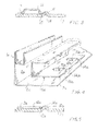
- Figure 1 is a perspective view, before being assembled together, of a faceplate (partly reproduced) and the reinforcement to be associated with it;
- Figure 2 is a perspective view of the assembled faceplate and reinforcement;
- Figure 3 is a section through the assembly means on termination of assembly;
- Figure 4 is a perspective view of the faceplate and reinforcement during assembly, but provided with a variant of the assembly means;
- Figure 5 is a section (similar to Figure 3) of the variant of the assembly means on termination of assembly;
- Figure 6 is a perspective view of the faceplate and reinforcement during assembly, but provided with a further variant of the assembly means;
- Figure 7 is a perspective view of the assembled faceplate and reinforcement of Figure 6;
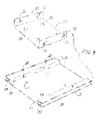
- Figure 8 is a perspective view of a different version of the faceplate and reinforcement before their assembly.
-
- With initial reference to Figures 1, 2, 3, the reference numeral 1 indicates a faceplate formed from a sheet metal profile bar having a
base side 2, afront side 3 at 90° to the base side, and achannel part 4 to the side of thefront side 3 and involving only a fraction (the upper fraction) of thefront side 3 to hence obtain in the faceplate alongitudinal groove 5 within which thereinforcement 6, of substantially the same height, is to be located. - The
reinforcement 6 is formed from a piece of U-shaped robust sheet metal having abase side 7, a front side 8 at 90° to the base side, and a right-angledthird side 9 having a width less than that of thebase side 7.Holes 10 are provided in the front side for fixing a conventional hinge, not shown, by screws. - According to the invention, the two components (faceplate and reinforcement) are provided with means for snap-fitting them together, making the use of spot welding, with all its contingent disadvantages and drawbacks, superfluous.
- Specifically, with regard to the embodiment of Figures 1, 2 and 3, two
bosses 11 are formed on thebase side 2 of the faceplate 1 by pressing in predetermined positions and at a predetermined distance apart, while on thebase side 7 of thereinforcement 6 two outwardly projecting rectilinear parallel groove-type guides (see Figure 3) indicated by 12 are formed, again by pressing, in predetermined positions and at a distance apart equal to that of thebosses 11, followed, aligned therewith, by a notch or recess 14 after aconnection piece 13. - For assembly, which can be easily automated, the
reinforcement 6 is rested with itsbase side 7 on thebase side 2 of the faceplate, precisely such that eachboss 11 of this latter penetrates into aguide 12 in the reinforcement. The reinforcement is then thrust totally in the direction of the arrow F to cause the bosses, by virtue of the intrinsic elasticity of the sheet metal, to pass beyond theconnection pieces 13 where they snap into the notches orrecesses 14, to settle therein. Stable and precise assembly of the parts is hence achieved, such as to bring thewalls 8 and 3 of the two components into mutual contact, as can be seen in Figure 2, with the reinforcement hence engaging in thegroove 5 of the faceplate. - A first variant is shown in Figures 4 and 5.
- In these figures, parts equal or corresponding to those already described are indicated by the same reference numerals associated with the letter "a". In practice, the covered
guides 12 are replaced bylong holes 12a. - Figure 4 shows the step in which the bosses 11 a are still within the guides, i.e. in this case within the
long holes 12a. - The invention also evidently includes solutions in which the
bosses 11, 11a are formed in thelower side 7, 7a of thereinforcement 6, with theguides recesses base wall - Two further variants are shown in Figures 6, 7 and in Figure 8 respectively.
- In Figures 6, 7, equal or corresponding parts are indicated by the same reference numerals associated with the letter "b". The variant of these figures can be used for faceplates of different dimensions and for right or left handed mounting. The
faceplate 1b presents on its base side 2b twocircular bosses 11 b (similar to the version of Figures 1, 2, 3) and a rectilinear boss 20 (similar to theguide 12 of Figure 3, which however is provided on the lower flange of the reinforcement), while thereinforcement 6b presents a pair of spaced-apart rectilinearparallel slots 21 in itslower flange 7b. Figure 7 shows the assembly of thereinforcement 6b to thefaceplate 1b, in which thebosses 11b snap-engage into a side Z of the reinforcement to retain it against thewall 3b of the faceplate, while therectilinear boss 20 prevents transverse movements and acts as a guide during assembly. Notches similar to the notches 14 (Figure 1) can be provided in the side Z where thebosses 11 b engage. - Figure 8 shows a different faceplate, indicated by 21, having a channel-
shaped part 22 along parallel opposing sides. Thefaceplate 24, which in this case is of U-shape, is mounted in the interspace defined between theends 23 of the channel-shaped parts. Twoholes 26 are provided in theflanges 25 of the U to be snap-engaged bycorresponding bosses 28, emerging from (formed in) theends 23.Holes 29 are provided for mounting the hinges.
Claims (8)
- A method for assembling a metal reinforcement member (6, 6a) onto a specific profiled sheet metal part (1, 1a), known as a faceplate, of a refrigerator, freezer or a similar appliance, to enable a hinge for the appliance door to be securely connected, characterised in that assembly is achieved by mutual snap-engagement between first means (14, 14a, Z, 26) and second means (11, 11a, 11b, 28) provided one in the metal reinforcement member (6, 6a, 6b, 24) and the other in the faceplate (1, 1a, 1b, 21).
- A method as claimed in claim 1, wherein the first means (14, 14a) are represented by recesses and the second means (11, 11a) by projections arranged to settle into said recesses.
- A method as claimed in the preceding claims, wherein the recesses (14, 14a) are associated with rectilinear guides (12, 12a) for the projections (11, 11 a).
- A method as claimed in the preceding claims, wherein the recesses (14, 14a) are separated from the associated rectilinear guides (12, 12a) and are aligned with said guides.
- A method as claimed in the preceding claims, wherein the recesses (14, 14a) and the associated rectilinear guides (12, 12a) are provided in a side (7, 7a) of the faceplate, the projections being provided on a side (2, 2a) of the faceplate (1, 1a), this latter side acting as a support for the reinforcement (6, 6a).
- A method as claimed in the preceding claims, wherein the rectilinear guides (12, 12a) are depressions or long holes.
- A method as claimed in claim 1, wherein the first means (Z) are represented by a free edge of a side (7b) of the reinforcement (6b), said reinforcement presenting at least one open ended slot (21) arranged to cooperate with a rectilinear boss (20) present on a side (2b) of the faceplate, said second means (11 b) being provided on said side (2b).
- A method as claimed in claim 1, wherein the first means (26) are represented by holes present in parallel opposing sides (25) of the reinforcement (24), the second means (28) being represented by corresponding bosses (28) provided on the facing ends (23) of channel-shaped parts (22) present in the faceplate (21).
Priority Applications (1)
| Application Number | Priority Date | Filing Date | Title |
|---|---|---|---|
| PL05100220T PL1566603T3 (en) | 2004-01-28 | 2005-01-14 | Method for assembling a reinforcement onto the faceplate of a refrigerator, freezer or the like |
Applications Claiming Priority (2)
| Application Number | Priority Date | Filing Date | Title |
|---|---|---|---|
| ITMI20040114 | 2004-01-28 | ||
| IT000114A ITMI20040114A1 (en) | 2004-01-28 | 2004-01-28 | METHOD FOR ASSEMBLING A REINFORCEMENT TO THE FRONT PANEL OF A FREEZER AND SIMILAR REFRIGERATOR |
Publications (2)
| Publication Number | Publication Date |
|---|---|
| EP1566603A1 true EP1566603A1 (en) | 2005-08-24 |
| EP1566603B1 EP1566603B1 (en) | 2007-11-21 |
Family
ID=34708520
Family Applications (1)
| Application Number | Title | Priority Date | Filing Date |
|---|---|---|---|
| EP05100220A Expired - Lifetime EP1566603B1 (en) | 2004-01-28 | 2005-01-14 | Method for assembling a reinforcement onto the faceplate of a refrigerator, freezer or the like |
Country Status (5)
| Country | Link |
|---|---|
| EP (1) | EP1566603B1 (en) |
| DE (1) | DE602005003380T2 (en) |
| ES (1) | ES2296071T3 (en) |
| IT (1) | ITMI20040114A1 (en) |
| PL (1) | PL1566603T3 (en) |
Cited By (6)
| Publication number | Priority date | Publication date | Assignee | Title |
|---|---|---|---|---|
| KR20060125408A (en) * | 2005-06-02 | 2006-12-06 | 엘지전자 주식회사 | Decorative cap mounting structure of door for refrigerator |
| CN103363769A (en) * | 2013-06-04 | 2013-10-23 | 海信容声(广东)冰箱有限公司 | Large-volume refrigerator body |
| CN105115222A (en) * | 2015-08-20 | 2015-12-02 | 洛阳晶城玻璃有限公司 | Door frame gusset plate applicable to refrigerator or refrigeration house |
| CN105115230A (en) * | 2015-08-20 | 2015-12-02 | 洛阳晶城玻璃有限公司 | Edge covering plate applicable to refrigerator door or refrigeration house door |
| US20190277556A1 (en) * | 2018-03-06 | 2019-09-12 | Bsh Hausgeraete Gmbh | Refrigerator |
| US11592231B2 (en) | 2020-09-30 | 2023-02-28 | Bsh Hausgeraete Gmbh | Refrigeration device with reinforced housing |
Citations (3)
| Publication number | Priority date | Publication date | Assignee | Title |
|---|---|---|---|---|
| US2332195A (en) * | 1941-07-26 | 1943-10-19 | Westinghouse Electric & Mfg Co | Sealed hinge mechanism |
| US4170391A (en) * | 1978-09-21 | 1979-10-09 | General Electric Company | Refrigerator cabinet construction |
| WO2002099346A1 (en) * | 2001-06-01 | 2002-12-12 | BSH Bosch und Siemens Hausgeräte GmbH | Body for a refrigerating device |
-
2004
- 2004-01-28 IT IT000114A patent/ITMI20040114A1/en unknown
-
2005
- 2005-01-14 EP EP05100220A patent/EP1566603B1/en not_active Expired - Lifetime
- 2005-01-14 DE DE602005003380T patent/DE602005003380T2/en not_active Expired - Lifetime
- 2005-01-14 PL PL05100220T patent/PL1566603T3/en unknown
- 2005-01-14 ES ES05100220T patent/ES2296071T3/en not_active Expired - Lifetime
Patent Citations (3)
| Publication number | Priority date | Publication date | Assignee | Title |
|---|---|---|---|---|
| US2332195A (en) * | 1941-07-26 | 1943-10-19 | Westinghouse Electric & Mfg Co | Sealed hinge mechanism |
| US4170391A (en) * | 1978-09-21 | 1979-10-09 | General Electric Company | Refrigerator cabinet construction |
| WO2002099346A1 (en) * | 2001-06-01 | 2002-12-12 | BSH Bosch und Siemens Hausgeräte GmbH | Body for a refrigerating device |
Cited By (9)
| Publication number | Priority date | Publication date | Assignee | Title |
|---|---|---|---|---|
| KR20060125408A (en) * | 2005-06-02 | 2006-12-06 | 엘지전자 주식회사 | Decorative cap mounting structure of door for refrigerator |
| CN103363769A (en) * | 2013-06-04 | 2013-10-23 | 海信容声(广东)冰箱有限公司 | Large-volume refrigerator body |
| CN103363769B (en) * | 2013-06-04 | 2015-06-24 | 海信容声(广东)冰箱有限公司 | Large-volume refrigerator body |
| CN105115222A (en) * | 2015-08-20 | 2015-12-02 | 洛阳晶城玻璃有限公司 | Door frame gusset plate applicable to refrigerator or refrigeration house |
| CN105115230A (en) * | 2015-08-20 | 2015-12-02 | 洛阳晶城玻璃有限公司 | Edge covering plate applicable to refrigerator door or refrigeration house door |
| US20190277556A1 (en) * | 2018-03-06 | 2019-09-12 | Bsh Hausgeraete Gmbh | Refrigerator |
| CN110230912A (en) * | 2018-03-06 | 2019-09-13 | 博西华电器(江苏)有限公司 | Refrigerator |
| US10627154B2 (en) * | 2018-03-06 | 2020-04-21 | Bsh Hausgeraete Gmbh | Refrigerator |
| US11592231B2 (en) | 2020-09-30 | 2023-02-28 | Bsh Hausgeraete Gmbh | Refrigeration device with reinforced housing |
Also Published As
| Publication number | Publication date |
|---|---|
| PL1566603T3 (en) | 2008-03-31 |
| EP1566603B1 (en) | 2007-11-21 |
| DE602005003380D1 (en) | 2008-01-03 |
| ITMI20040114A1 (en) | 2004-04-28 |
| ES2296071T3 (en) | 2008-04-16 |
| DE602005003380T2 (en) | 2008-04-03 |
Similar Documents
| Publication | Publication Date | Title |
|---|---|---|
| CA2123279C (en) | A drawer | |
| EP1566603B1 (en) | Method for assembling a reinforcement onto the faceplate of a refrigerator, freezer or the like | |
| AU2010268131A1 (en) | Drawer | |
| CA2452516C (en) | Sectional upward acting door and method of assembly | |
| KR20080099852A (en) | Guide rail with cover strip for linear bearing | |
| FI94454C (en) | A sheet metal door frame and a method of installing it in a doorway | |
| AU701256B2 (en) | Switchgear cubicle with frame and cladding | |
| KR101864568B1 (en) | One-touch assembly type cable tray for electrical work | |
| GB2331404A (en) | Electrical gasket providing shielding for housings | |
| GB2105428A (en) | Improvements in or relating to a corner guide for drive rod fittings on windows, doors or the like | |
| US20090151136A1 (en) | Clip Fixing Assembly For Fixing A Fitting To A Thin Wall Provided With Openings | |
| KR0167594B1 (en) | Plastic holder for fixing the support strip for glass plates or filling plates to the frame of a window or door | |
| FI106159B (en) | Cover for a wall duct | |
| JP3769265B2 (en) | Grating and its assembly method | |
| JPH08318824A (en) | Snap assembly knuckle for windshield wiper blade | |
| KR101792495B1 (en) | Wind-proof Assembly on Door Floor and Installation Structure Therewith | |
| HU224023B1 (en) | Drive rod fitting with corner deflection | |
| RU233322U1 (en) | FRAME PROFILE | |
| KR100702561B1 (en) | Cable Entry Device for Outdoor Telecommunication Equipment | |
| CN222955109U (en) | Fixing piece for household appliance, positioning piece and household appliance | |
| US10267076B2 (en) | Connecting device and window or door comprising a connecting device | |
| EP1619060A2 (en) | Sealing joint between vehicle bodywork components | |
| CN223695296U (en) | Installation component, household electrical appliance component and cabinet body component | |
| EP1942235A2 (en) | Cladding systems | |
| JPS5928950B2 (en) | Device for tightening conductors, especially conductors |
Legal Events
| Date | Code | Title | Description |
|---|---|---|---|
| PUAI | Public reference made under article 153(3) epc to a published international application that has entered the european phase |
Free format text: ORIGINAL CODE: 0009012 |
|
| AK | Designated contracting states |
Kind code of ref document: A1 Designated state(s): AT BE BG CH CY CZ DE DK EE ES FI FR GB GR HU IE IS IT LI LT LU MC NL PL PT RO SE SI SK TR |
|
| AX | Request for extension of the european patent |
Extension state: AL BA HR LV MK YU |
|
| 17P | Request for examination filed |
Effective date: 20060221 |
|
| AKX | Designation fees paid |
Designated state(s): DE ES FR GB IT PL |
|
| GRAP | Despatch of communication of intention to grant a patent |
Free format text: ORIGINAL CODE: EPIDOSNIGR1 |
|
| GRAS | Grant fee paid |
Free format text: ORIGINAL CODE: EPIDOSNIGR3 |
|
| GRAA | (expected) grant |
Free format text: ORIGINAL CODE: 0009210 |
|
| AK | Designated contracting states |
Kind code of ref document: B1 Designated state(s): DE ES FR GB IT PL |
|
| REG | Reference to a national code |
Ref country code: GB Ref legal event code: FG4D |
|
| REF | Corresponds to: |
Ref document number: 602005003380 Country of ref document: DE Date of ref document: 20080103 Kind code of ref document: P |
|
| REG | Reference to a national code |
Ref country code: PL Ref legal event code: T3 |
|
| REG | Reference to a national code |
Ref country code: ES Ref legal event code: FG2A Ref document number: 2296071 Country of ref document: ES Kind code of ref document: T3 |
|
| ET | Fr: translation filed | ||
| PLBE | No opposition filed within time limit |
Free format text: ORIGINAL CODE: 0009261 |
|
| STAA | Information on the status of an ep patent application or granted ep patent |
Free format text: STATUS: NO OPPOSITION FILED WITHIN TIME LIMIT |
|
| 26N | No opposition filed |
Effective date: 20080822 |
|
| REG | Reference to a national code |
Ref country code: FR Ref legal event code: PLFP Year of fee payment: 12 |
|
| REG | Reference to a national code |
Ref country code: FR Ref legal event code: PLFP Year of fee payment: 13 |
|
| PGFP | Annual fee paid to national office [announced via postgrant information from national office to epo] |
Ref country code: ES Payment date: 20161214 Year of fee payment: 13 Ref country code: PL Payment date: 20161213 Year of fee payment: 13 |
|
| REG | Reference to a national code |
Ref country code: FR Ref legal event code: PLFP Year of fee payment: 14 |
|
| PGFP | Annual fee paid to national office [announced via postgrant information from national office to epo] |
Ref country code: FR Payment date: 20171211 Year of fee payment: 14 |
|
| PGFP | Annual fee paid to national office [announced via postgrant information from national office to epo] |
Ref country code: GB Payment date: 20180110 Year of fee payment: 14 Ref country code: DE Payment date: 20180103 Year of fee payment: 14 |
|
| PGFP | Annual fee paid to national office [announced via postgrant information from national office to epo] |
Ref country code: IT Payment date: 20180122 Year of fee payment: 14 |
|
| PG25 | Lapsed in a contracting state [announced via postgrant information from national office to epo] |
Ref country code: PL Free format text: LAPSE BECAUSE OF NON-PAYMENT OF DUE FEES Effective date: 20180114 |
|
| REG | Reference to a national code |
Ref country code: ES Ref legal event code: FD2A Effective date: 20190731 |
|
| REG | Reference to a national code |
Ref country code: DE Ref legal event code: R119 Ref document number: 602005003380 Country of ref document: DE |
|
| GBPC | Gb: european patent ceased through non-payment of renewal fee |
Effective date: 20190114 |
|
| PG25 | Lapsed in a contracting state [announced via postgrant information from national office to epo] |
Ref country code: FR Free format text: LAPSE BECAUSE OF NON-PAYMENT OF DUE FEES Effective date: 20190131 Ref country code: ES Free format text: LAPSE BECAUSE OF NON-PAYMENT OF DUE FEES Effective date: 20180115 Ref country code: DE Free format text: LAPSE BECAUSE OF NON-PAYMENT OF DUE FEES Effective date: 20190801 |
|
| PG25 | Lapsed in a contracting state [announced via postgrant information from national office to epo] |
Ref country code: GB Free format text: LAPSE BECAUSE OF NON-PAYMENT OF DUE FEES Effective date: 20190114 |
|
| PG25 | Lapsed in a contracting state [announced via postgrant information from national office to epo] |
Ref country code: IT Free format text: LAPSE BECAUSE OF NON-PAYMENT OF DUE FEES Effective date: 20190114 |