EP1566477A1 - Flüssigkeitsführendes elektrisches Haushaltsgerät - Google Patents
Flüssigkeitsführendes elektrisches Haushaltsgerät Download PDFInfo
- Publication number
- EP1566477A1 EP1566477A1 EP05100684A EP05100684A EP1566477A1 EP 1566477 A1 EP1566477 A1 EP 1566477A1 EP 05100684 A EP05100684 A EP 05100684A EP 05100684 A EP05100684 A EP 05100684A EP 1566477 A1 EP1566477 A1 EP 1566477A1
- Authority
- EP
- European Patent Office
- Prior art keywords
- motor
- liquid
- pump
- appliance according
- measuring circuit
- Prior art date
- Legal status (The legal status is an assumption and is not a legal conclusion. Google has not performed a legal analysis and makes no representation as to the accuracy of the status listed.)
- Withdrawn
Links
- 239000007788 liquid Substances 0.000 title claims description 16
- 238000004804 winding Methods 0.000 claims abstract description 39
- 238000010438 heat treatment Methods 0.000 claims description 8
- 238000005259 measurement Methods 0.000 claims description 6
- 239000012530 fluid Substances 0.000 abstract description 3
- 238000012544 monitoring process Methods 0.000 description 9
- 238000004140 cleaning Methods 0.000 description 4
- 230000000875 corresponding effect Effects 0.000 description 3
- XLYOFNOQVPJJNP-UHFFFAOYSA-N water Substances O XLYOFNOQVPJJNP-UHFFFAOYSA-N 0.000 description 3
- 238000010586 diagram Methods 0.000 description 2
- 238000011010 flushing procedure Methods 0.000 description 2
- 238000007373 indentation Methods 0.000 description 2
- 230000006698 induction Effects 0.000 description 2
- 239000000463 material Substances 0.000 description 2
- 238000005406 washing Methods 0.000 description 2
- 238000010276 construction Methods 0.000 description 1
- 230000001276 controlling effect Effects 0.000 description 1
- 230000002596 correlated effect Effects 0.000 description 1
- 230000008878 coupling Effects 0.000 description 1
- 238000010168 coupling process Methods 0.000 description 1
- 238000005859 coupling reaction Methods 0.000 description 1
- 230000001419 dependent effect Effects 0.000 description 1
- 238000001514 detection method Methods 0.000 description 1
- 230000000694 effects Effects 0.000 description 1
- 238000009434 installation Methods 0.000 description 1
- 230000002452 interceptive effect Effects 0.000 description 1
- 238000005086 pumping Methods 0.000 description 1
- 238000011084 recovery Methods 0.000 description 1
- 239000004065 semiconductor Substances 0.000 description 1
- 239000007921 spray Substances 0.000 description 1
- 230000009897 systematic effect Effects 0.000 description 1
Images

Classifications
-
- A—HUMAN NECESSITIES
- A47—FURNITURE; DOMESTIC ARTICLES OR APPLIANCES; COFFEE MILLS; SPICE MILLS; SUCTION CLEANERS IN GENERAL
- A47L—DOMESTIC WASHING OR CLEANING; SUCTION CLEANERS IN GENERAL
- A47L15/00—Washing or rinsing machines for crockery or tableware
- A47L15/42—Details
- A47L15/4214—Water supply, recirculation or discharge arrangements; Devices therefor
- A47L15/4225—Arrangements or adaption of recirculation or discharge pumps
-
- D—TEXTILES; PAPER
- D06—TREATMENT OF TEXTILES OR THE LIKE; LAUNDERING; FLEXIBLE MATERIALS NOT OTHERWISE PROVIDED FOR
- D06F—LAUNDERING, DRYING, IRONING, PRESSING OR FOLDING TEXTILE ARTICLES
- D06F39/00—Details of washing machines not specific to a single type of machines covered by groups D06F9/00 - D06F27/00
- D06F39/08—Liquid supply or discharge arrangements
- D06F39/083—Liquid discharge or recirculation arrangements
- D06F39/085—Arrangements or adaptations of pumps
-
- A—HUMAN NECESSITIES
- A47—FURNITURE; DOMESTIC ARTICLES OR APPLIANCES; COFFEE MILLS; SPICE MILLS; SUCTION CLEANERS IN GENERAL
- A47L—DOMESTIC WASHING OR CLEANING; SUCTION CLEANERS IN GENERAL
- A47L15/00—Washing or rinsing machines for crockery or tableware
- A47L15/42—Details
- A47L15/4287—Temperature measuring or regulating arrangements
-
- D—TEXTILES; PAPER
- D06—TREATMENT OF TEXTILES OR THE LIKE; LAUNDERING; FLEXIBLE MATERIALS NOT OTHERWISE PROVIDED FOR
- D06F—LAUNDERING, DRYING, IRONING, PRESSING OR FOLDING TEXTILE ARTICLES
- D06F39/00—Details of washing machines not specific to a single type of machines covered by groups D06F9/00 - D06F27/00
- D06F39/04—Heating arrangements
-
- A—HUMAN NECESSITIES
- A47—FURNITURE; DOMESTIC ARTICLES OR APPLIANCES; COFFEE MILLS; SPICE MILLS; SUCTION CLEANERS IN GENERAL
- A47L—DOMESTIC WASHING OR CLEANING; SUCTION CLEANERS IN GENERAL
- A47L2401/00—Automatic detection in controlling methods of washing or rinsing machines for crockery or tableware, e.g. information provided by sensors entered into controlling devices
- A47L2401/08—Drain or recirculation pump parameters, e.g. pump rotational speed or current absorbed by the motor
-
- A—HUMAN NECESSITIES
- A47—FURNITURE; DOMESTIC ARTICLES OR APPLIANCES; COFFEE MILLS; SPICE MILLS; SUCTION CLEANERS IN GENERAL
- A47L—DOMESTIC WASHING OR CLEANING; SUCTION CLEANERS IN GENERAL
- A47L2401/00—Automatic detection in controlling methods of washing or rinsing machines for crockery or tableware, e.g. information provided by sensors entered into controlling devices
- A47L2401/30—Variation of electrical, magnetical or optical quantities
-
- A—HUMAN NECESSITIES
- A47—FURNITURE; DOMESTIC ARTICLES OR APPLIANCES; COFFEE MILLS; SPICE MILLS; SUCTION CLEANERS IN GENERAL
- A47L—DOMESTIC WASHING OR CLEANING; SUCTION CLEANERS IN GENERAL
- A47L2501/00—Output in controlling method of washing or rinsing machines for crockery or tableware, i.e. quantities or components controlled, or actions performed by the controlling device executing the controlling method
- A47L2501/06—Water heaters
Definitions
- the present invention relates to a household electrical appliance with a during operation of the device at least partially filled with liquid Chamber and a pump driven by a motor Circulating the liquid.
- a household appliance it can in particular a dishwasher or washing machine, and at the pump to a drain pump, the cleaning solution A lower part of the chamber sucks to keep it in the chamber arranged to be cleaned, to be cleaned or sprayed out of the chamber pump out.
- the cleaning solution in such a household appliance must be on a predetermined operating temperature can be maintained.
- a temperature sensor such as a Thermocouple in as close as possible thermal contact with the Cleaning solution placed.
- the installation of such a sensor requires Costs and labor.
- the invention makes use of the fact that the windings are for pumping Of the fluid used pump motor often in thermal Contact with the liquid leading parts so that theirs Temperature closely follows that of the liquid, and that most for the Making the winding suitable materials one have temperature-dependent resistivity, so off Fluctuations in the resistance of the windings a conclusion to the temperature of the windings is possible, in turn, with the Fluid is closely correlated. From the development of the electric Resistance value of the winding arrangement is therefore a conclusion possible on the temperature of the liquid.
- a household appliance of the above type has over a heater for heating the liquid and a Control device for controlling the operation of the heater. These can suitably the detected resistance value for the Use temperature control.
- the motor of the pump of the machine according to the invention a wet runner, d. H. the runner is in a filled with the liquid Housed chamber forming part of the pump.
- This construction ensures a close thermal coupling of both the runner and also of the chamber surrounding the stator of the engine to the Liquid.
- the winding assembly whose resistance is measured, can be a single winding, the entirety of the windings of the motor or a between these two extremes lying number of windings include.
- the measuring circuit performs the Resistance measurement preferably with the engine off.
- the resistance value of the winding assembly preferably a Current measuring circuit for measuring the current flow through the Inverter and / or a voltage measuring circuit for measuring the Input voltage of the inverter provided from the Measurement results of the resistance value taking into account the Voltage drop in the inverter can be calculated.
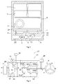
- Fig. 1 shows a schematic section through a dishwasher with a rinsing chamber 1, in the usual way baskets 2, 3 on rails guided are pulled out.
- a flushing water filter 4 In a depression at the bottom of the Flushing chamber 1 is a flushing water filter 4, through which a pump 5 explained in more detail later with reference to FIGS. 2 and 3 Rinsing aspirates to rotatable about lines 12, 13 rotatably mounted To feed nozzle arms 6, 7, each mounted under the baskets 2, 3 are to spray on the dishes contained therein.
- An electrical Heating rod 8 is mounted on the bottom of the washing chamber 1 and serves for Heating the rinse liquor.
- the pump 5 is driven by a brushless DC motor 9.
- FIG. 2 shows in more detail in shape a block diagram of the structure of the electronics block 20.
- the motor. 9 has three stator windings, labeled U, V, W here in one Star configuration are interconnected.
- the supply electronics block 20 includes a mains rectifier 21, which is an intermediate DC voltage supplies. This DC intermediate voltage feeds three phases Inverter 22, each of which two switches in series SU1, SU2 or SV1, SV2 or SW1, SW2, each in the form of a Power transistor with parallel recovery diode includes. The point between two switches of each phase is assigned one each Winding U, V or W connected to the engine.
- each switch is by a switching pattern generator 23rd controlled, the one for the current phase ⁇ of the motor shaft repr ⁇ sentative signal from a phase detector 24 receives and based this phase signal, the energization of the St ⁇ nderwicklened U, V, W of the Motor 9 so determined that the of the stator windings U, V, W in Motor 9 generated a certain advance of the phase magnetic field from which its owner has and drives this.
- the phase detector 24 may be replaced by one or more Be formed magnetic field sensors such as Hall sensors, the Magnetic field of the rotor or of rotating coupled with the rotor Magnets are exposed. Preferably, it is a pure electronic phase detector, such as. As described in US-A-5859520, the one zero crossing of the one in a temporarily de-energized Winding U, V or W of the motor through the magnetic field of the rotor bank evaluates the induced electromotive force, in order to derive the phase ⁇ der der L ⁇ ufers derive.
- the phase signal supplied by the phase detector 24 is also from a Speed measuring circuit 25 receive the speed n of the motor 9th by making a time derivative, measuring the period or Like. Determined.
- the speed measuring circuit 25 supplies a detected speed n repr ⁇ sentative signal to a monitoring circuit 26.
- a current measuring circuit 27 has two inputs, with the two Terminals of a measuring resistor 28 are connected in Row with the inverter 22 between the output terminals of Mains rectifier 21 is connected.
- the fliei through the measuring resistor 28 end of current is therefore the sum of the three phases of the Inverter 22 flowing currents.
- a voltage measuring circuit 29 has two inputs parallel to the Inverter 22 to the two outputs of the mains rectifier 21st are connected and so capture the value of the intermediate voltage.
- Outputs of the three measuring circuits 25, 27, 29 are connected to the ⁇ ' monitoring circuit 26, so at any time the current values the speed n, the DC link voltage and the Interrogate DC link current. Based on the amperage and Voltage readings is the ⁇ monitoring circuit 26 capable of from the inverter (and thus ultimately from the motor 9) recorded to calculate electrical power. This power is available when the pump 5 properly, in a fixed relationship with the speed n. This relationship is due to the shape of the lines 12, 13 determined by which the Spóllauge is pumped. This Context is in the form of a characteristic curve in a memory of the ⁇ ' Monitor circuit 25 stored.
- the ⁇ monitoring circuit 26 is capable of interfering with the interference Lye circulation, for example due to low water level in the Spó lhunt 1 or by blockage of the filter 4, to detect and if necessary, mainframes to protect the motor 9 to meet.
- Mainframes may be e.g. the shutdown of the engine or the entire Spólmaschine, a Róckspólen the filter 4, to solve the blockage, etc. be.
- the ⁇ monitoring circuit 26 is also able to the ohmic resistance of an arrangement of windings of the motor. 9 to investigate.
- This ohmic resistance is based on a resistance temperature characteristic of the material of the windings U, V, W a Ró close to their temperature.
- the operation of various Functional components of the Spólmaschine based on a user controls a value for the temperature of the Spó lwassers requires, he orders a temporary interruption of the operation the pump 5 on.
- the motor 9 is stopped by the Speed with which output from the generator 23 Switching pattern successive, is reduced, until finally one of arbitrarily chosen orientation of the magnetic field in motor 9 corresponding switching pattern is reached. From this switching pattern is not indexed so that the rotor of the motor 9 in one of the Orientation of the magnetic field in this circuit pattern corresponding Position remains. In this switching pattern, e.g.
- the switches SU1 and SV2 be open and all others closed, leaving a stream in Row through the windings U, V of the motor flie ⁇ t, or it can Switches SU1, SV2, SW2 closed and the others open so that Current flows through the winding U and then onto the windings V, W distributed.
- the ⁇ monitoring circuit 26 reads the signals from the measuring circuits 27, 29 recorded values of current and voltage. From the measured Voltage is subtracted a value that corresponds to the voltage drop in cascaded current-carrying switches such as SU1, SV2 of the inverter corresponds, and the difference is obtained with the measured current value is related to an ohmic To obtain resistance value of the current supplied windings. On the basis of a Resistance temperature characteristic, e.g. in one of the ⁇ ' monitoring circuit 26 associated semiconductor memory device can be stored, the ⁇ 'monitoring circuit 26 determines the measured resistance value corresponding temperature Winding arrangement.
- FIG. 2 includes a symbolized as a dashed frame microcontroller 31 the Components 23 to 27 and 29; the programmer 30, not only the pump 5, but also removed from her components such as the Heating rod 8 and inlet and outlet valves for the supply and discharge of Water in and out of the Spólhunt controls and commands a user processed is spatially separated from the microcontroller 31.
- Fig. 3 shows in one Section one embodiment of a unit of pump 5, motor 9 and Control electronics that meet this requirement particularly well.
- the pump 5 is a Flógelpumpe with a housing from a front Housing shell 41 and a pot-shaped indented shield 42, the limit a one-piece pump chamber 40.
- the pump chamber 40 is a Flógelrad 43 and, in the potff Einbmmiges indentation of the shield 42nd intervening, a bank 44 of the brushless DC motor 9 accommodated.
- the L ⁇ ufer 44 is in the pumped by the pump Fló dipped and cooled by this liquid.
- the essentially ringf ⁇ ohms 45 of the motor 9, which includes the windings U, V, W, is mounted on the edge of a housing shell 46, in which a circuit board 47 is anchored, tr ⁇ gt the microcontroller 31 and the measuring resistor 28.
- the assembly of Gehasuseschale 46 and St ⁇ nder 45 is in the manner of a Bechers outside over the sign 42 gestólpt.
- the windings U, V, W are here only through the wall of the pot-shaped indentation of the shield 42 separated from the Spóllauge, which in the pump chamber 40 also the bank 44 umspólt. Since the liquor in the pump chamber 40 standig their temperature is a good average for the Temperature of the liquor in the Spöllhunt 1.
- the temperature is the St ⁇ Windings closely coupled to the Spóllauge. In the simplest case the temperature of the windings is equated with that of the Spóllauge.
Landscapes
- Engineering & Computer Science (AREA)
- Textile Engineering (AREA)
- Water Supply & Treatment (AREA)
- Control Of Motors That Do Not Use Commutators (AREA)
Abstract
Description
- Fig. 1
- einen schematischen Schnitt durch eine erfindungsgemäße Geschirrspülmaschine;
- Fig. 2
- ein Blockdiagramm des Motors der Umwälzpumpe der Spülmaschine aus Fig. 1 sowie von dessen Versorgungselektronik;
- Fig. 3
- einen Schnitt durch eine Baugruppe, in der die Pumpe, der Motor und die Versorgungselektronik zusammengefasst sind.
ermittelt und die darauf zurückgehende Temperaturerhöhung ΔT gemäß ΔT =

t den gegenwärtigen Zeitpunkt
n die Wärmekapazität des Ständers in JK-1 und
α die Zeitspanne bezeichnet, die benötigt wird, um eine Temperaturdifferenz zwischen Ständer und Lauge auf 1/e abklingen zu lassen.
Claims (9)
- Elektrisches Haushaltsgerät mit einer im Betrieb des Geräts wenigstens zum Teil mit Flüssigkeit gefüllten Kammer (1), einer Pumpe (5) zum Umwälzen der Flüssigkeit und einem die Pumpe (5) antreibenden Motor (9), der eine in thermischem Kontakt mit der Flüssigkeit stehende Wicklungsanordnung (U, V, W) aufweist, dadurch gekennzeichnet, dass der Wicklungsanordnung (U, V, W) eine Messschaltung (24-29) zum Erfassen des elektrischen Widerstandswertes der Wicklungsanordnung zugeordnet ist.
- Elektrisches Haushaltsgerät nach Anspruch 1, gekennzeichnet durch eine Heizeinrichtung (8) zum Erhitzen der Flüssigkeit und eine Steuereinrichtung (30) zum Steuern des Betriebs der Heizeinrichtung anhand des erfassten Widerstandswerts.
- Elektrisches Haushaltsgerät nach Anspruch 1 oder 2, dadurch gekennzeichnet, dass der Motor (9) einen in einer mit der Flüssigkeit gefüllten Kammer (40) der Pumpe (5) angeordneten Läufer (44) aufweist.
- Elektrisches Haushaltsgerät nach Anspruch 3, dadurch gekennzeichnet, dass die Wicklungsanordnung (U, V, W), der die Messschaltung (24-29) zugeordnet ist, Teil eines Ständers (45) des Motors (9) ist.
- Elektrisches Haushaltsgerät nach Anspruch 4, dadurch gekennzeichnet, dass eine Wand der Kammer (40) der Pumpe (5) sich in einem Luftspalt zwischen Läufer (44) und Ständer (45) erstreckt.
- Elektrisches Haushaltsgerät nach einem der vorhergehenden Ansprüche, dadurch gekennzeichnet, dass die Wicklungsanordnung (U, V, W)die Gesamtheit der Wicklungen des Motors oder zwei in Reihe verbundene Wicklungen umfasst.
- Elektrisches Haushaltsgerät nach einem der vorhergehenden Ansprüche, dadurch gekennzeichnet, dass die Messschaltung (24-29) eingerichtet ist, eine Messung des Widerstands der Wicklung jeweils bei stillstehendem Motor durchzuführen.
- Elektrisches Haushaltsgerät nach einem der vorhergehenden Ansprüche,
dadurch gekennzeichnet, dass der Motor (9) über einen Wechselrichter (22) gespeist ist, und dass die Messschaltung (24-29) eine Strommessschaltung (27) zum Messen des Stromflusses durch den Wechselrichter (22) umfasst. - Elektrisches Haushaltsgerät nach einem der vorhergehenden Ansprüche, dadurch gekennzeichnet, dass der Motor (9) über einen Wechselrichter (22) gespeist ist, und dass die Messschaltung (24-29) eine Spannungsmessschaltung (29) zum Messen der Eingangsspannung des Wechselrichters (22) umfasst.
Applications Claiming Priority (2)
| Application Number | Priority Date | Filing Date | Title |
|---|---|---|---|
| DE102004007246 | 2004-02-13 | ||
| DE102004007246A DE102004007246A1 (de) | 2004-02-13 | 2004-02-13 | Flüssigkeitsführendes elektrisches Haushaltsgerät |
Publications (1)
| Publication Number | Publication Date |
|---|---|
| EP1566477A1 true EP1566477A1 (de) | 2005-08-24 |
Family
ID=34706819
Family Applications (1)
| Application Number | Title | Priority Date | Filing Date |
|---|---|---|---|
| EP05100684A Withdrawn EP1566477A1 (de) | 2004-02-13 | 2005-02-01 | Flüssigkeitsführendes elektrisches Haushaltsgerät |
Country Status (2)
| Country | Link |
|---|---|
| EP (1) | EP1566477A1 (de) |
| DE (1) | DE102004007246A1 (de) |
Cited By (8)
| Publication number | Priority date | Publication date | Assignee | Title |
|---|---|---|---|---|
| EP1762169A3 (de) * | 2005-09-09 | 2008-08-06 | BSH Bosch und Siemens Hausgeräte GmbH | Wasserführendes Haushaltgerät mit einer Pumpe |
| CN1702334B (zh) * | 2004-05-12 | 2011-11-23 | 阿斯科尔控股有限公司 | 尤其用于洗衣机的带有同步电机并装有流体加热装置的流体循环泵 |
| DE102014206119A1 (de) | 2013-12-18 | 2015-06-18 | BSH Hausgeräte GmbH | Verfahren zum Betreiben einer Pumpe in einem Haushaltsgerät und wasserführendes Haushaltsgerät |
| EP2954828A1 (de) * | 2014-06-12 | 2015-12-16 | LG Electronics Inc. | Geschirrspülmaschine und steuerungsverfahren dafür |
| EP2954829A1 (de) * | 2014-06-12 | 2015-12-16 | LG Electronics Inc. | Steuerungsverfahren für einen geschirrspüler |
| CN106367912A (zh) * | 2015-07-22 | 2017-02-01 | 东芝生活电器株式会社 | 滚筒式洗衣机 |
| DE102017211569A1 (de) | 2017-07-06 | 2019-01-10 | BSH Hausgeräte GmbH | Verfahren zum Betrieb einer Waschmaschine mit verbessertem Pumpbetrieb bei zweiphasigen Fluiden und hierzu geeignete Waschmaschine |
| DE102017211573A1 (de) | 2017-07-06 | 2019-01-10 | BSH Hausgeräte GmbH | Verfahren zum Betrieb einer Waschmaschine mit verbesserter Pumpenzustandserkennung und hierzu geeignete Waschmaschine |
Citations (4)
| Publication number | Priority date | Publication date | Assignee | Title |
|---|---|---|---|---|
| DE2938883A1 (de) * | 1979-09-26 | 1981-04-09 | Bosch-Siemens Hausgeräte GmbH, 7000 Stuttgart | Heizung zum erwaermen der spuelfluessigkeit in einer geschirrspuelmaschine |
| US5158436A (en) * | 1990-03-29 | 1992-10-27 | Grundfos International A/S | Pump with speed controller responsive to temperature |
| JPH06323295A (ja) * | 1993-05-17 | 1994-11-22 | Tokyo Electric Power Co Inc:The | 低温液用ポンプのクールダウンおよびホットアップ方法 |
| DE10142525A1 (de) * | 2001-08-30 | 2003-03-27 | Miele & Cie | Umwälzpumpe mit integrierter Spülwasser-Heizungseinrichtung und einem Temperatur-Sicherheitsschalter |
-
2004
- 2004-02-13 DE DE102004007246A patent/DE102004007246A1/de not_active Withdrawn
-
2005
- 2005-02-01 EP EP05100684A patent/EP1566477A1/de not_active Withdrawn
Patent Citations (4)
| Publication number | Priority date | Publication date | Assignee | Title |
|---|---|---|---|---|
| DE2938883A1 (de) * | 1979-09-26 | 1981-04-09 | Bosch-Siemens Hausgeräte GmbH, 7000 Stuttgart | Heizung zum erwaermen der spuelfluessigkeit in einer geschirrspuelmaschine |
| US5158436A (en) * | 1990-03-29 | 1992-10-27 | Grundfos International A/S | Pump with speed controller responsive to temperature |
| JPH06323295A (ja) * | 1993-05-17 | 1994-11-22 | Tokyo Electric Power Co Inc:The | 低温液用ポンプのクールダウンおよびホットアップ方法 |
| DE10142525A1 (de) * | 2001-08-30 | 2003-03-27 | Miele & Cie | Umwälzpumpe mit integrierter Spülwasser-Heizungseinrichtung und einem Temperatur-Sicherheitsschalter |
Non-Patent Citations (1)
| Title |
|---|
| PATENT ABSTRACTS OF JAPAN vol. 1995, no. 02 31 March 1995 (1995-03-31) * |
Cited By (17)
| Publication number | Priority date | Publication date | Assignee | Title |
|---|---|---|---|---|
| CN1702334B (zh) * | 2004-05-12 | 2011-11-23 | 阿斯科尔控股有限公司 | 尤其用于洗衣机的带有同步电机并装有流体加热装置的流体循环泵 |
| EP1762169A3 (de) * | 2005-09-09 | 2008-08-06 | BSH Bosch und Siemens Hausgeräte GmbH | Wasserführendes Haushaltgerät mit einer Pumpe |
| DE102014206119A1 (de) | 2013-12-18 | 2015-06-18 | BSH Hausgeräte GmbH | Verfahren zum Betreiben einer Pumpe in einem Haushaltsgerät und wasserführendes Haushaltsgerät |
| DE102014206119B4 (de) * | 2013-12-18 | 2016-09-22 | BSH Hausgeräte GmbH | Verfahren zum Betreiben einer Pumpe in einem Haushaltsgerät und wasserführendes Haushaltsgerät |
| EP2954829A1 (de) * | 2014-06-12 | 2015-12-16 | LG Electronics Inc. | Steuerungsverfahren für einen geschirrspüler |
| CN105167728A (zh) * | 2014-06-12 | 2015-12-23 | Lg电子株式会社 | 洗碗机及洗碗机的控制方法 |
| CN105286744A (zh) * | 2014-06-12 | 2016-02-03 | Lg电子株式会社 | 洗碗机及洗碗机的控制方法 |
| AU2015203124B2 (en) * | 2014-06-12 | 2016-09-15 | Lg Electronics Inc. | Dishwasher and Control Method for the Same |
| EP2954828A1 (de) * | 2014-06-12 | 2015-12-16 | LG Electronics Inc. | Geschirrspülmaschine und steuerungsverfahren dafür |
| AU2015203138B2 (en) * | 2014-06-12 | 2017-05-18 | Lg Electronics, Inc. | Dishwasher and Control Method Thereof |
| US9839944B2 (en) | 2014-06-12 | 2017-12-12 | Lg Electronics Inc. | Dishwasher and control method thereof |
| US9844801B2 (en) | 2014-06-12 | 2017-12-19 | Lg Electronics Inc. | Dishwasher |
| CN105167728B (zh) * | 2014-06-12 | 2019-01-29 | Lg电子株式会社 | 洗碗机及洗碗机的控制方法 |
| CN106367912A (zh) * | 2015-07-22 | 2017-02-01 | 东芝生活电器株式会社 | 滚筒式洗衣机 |
| CN106367912B (zh) * | 2015-07-22 | 2019-04-05 | 东芝生活电器株式会社 | 滚筒式洗衣机 |
| DE102017211569A1 (de) | 2017-07-06 | 2019-01-10 | BSH Hausgeräte GmbH | Verfahren zum Betrieb einer Waschmaschine mit verbessertem Pumpbetrieb bei zweiphasigen Fluiden und hierzu geeignete Waschmaschine |
| DE102017211573A1 (de) | 2017-07-06 | 2019-01-10 | BSH Hausgeräte GmbH | Verfahren zum Betrieb einer Waschmaschine mit verbesserter Pumpenzustandserkennung und hierzu geeignete Waschmaschine |
Also Published As
| Publication number | Publication date |
|---|---|
| DE102004007246A1 (de) | 2005-09-01 |
Similar Documents
| Publication | Publication Date | Title |
|---|---|---|
| EP1711099B1 (de) | Flüssigkeitsführendes elektrisches haushaltsgerät | |
| DE102007052091B4 (de) | Verfahren zur Fördervolumenbestimmung | |
| EP2194833B1 (de) | Verfahren zum Betreiben eines wasserführenden Haushaltsgeräts, sowie wasserführendes Haushaltsgerät | |
| EP2276388B1 (de) | Verfahren zum steuern eines füllvorgangs eines wasserführenden haushaltsgeräts | |
| EP2162045B1 (de) | Geschirrspülmaschine mit einer pumpe mit einem bürstenlosen permanentmagnetmotor | |
| DE102011000287B4 (de) | Verfahren zur Einstellung eines von einer Umwälzpumpe in einem wasserführenden Haushaltgerät geförderten Volumenstroms | |
| DE102007030072A1 (de) | Elektrischen Antriebseinrichtung für ein Wasserführendes Haushaltsgerät | |
| DE602004007488T2 (de) | Flüssigkeitsumwälzpumpe mit einem Synchronmotor, ausgestattet mit einer Einrichtung zum Heizen der Flüssigkeit, insbesondere für Waschmaschinen | |
| EP2672875B1 (de) | Geschirrspülmaschine und verfahren zur fehlerdetektion in einer geschirrspülmaschine | |
| DE102014206119B4 (de) | Verfahren zum Betreiben einer Pumpe in einem Haushaltsgerät und wasserführendes Haushaltsgerät | |
| EP2413774B1 (de) | Verfahren zum betreiben eines wasserführenden haushaltsgeräts | |
| DE102004007246A1 (de) | Flüssigkeitsführendes elektrisches Haushaltsgerät | |
| WO2008046852A1 (de) | Verfahren zum schutz eines heizelementes sowie heizvorrichtung | |
| DE102010063950A1 (de) | Haushaltsgerät mit einem Antriebsmotor und Verfahren zum Betreiben eines solchen Haushaltsgerät | |
| EP0478807B1 (de) | Waschautomat mit einer Überwachung der Motortemperatur | |
| WO2013131847A1 (de) | Wasserführendes haushaltsgerät mit zumindest einer motorgetriebenen pumpe und einer heizeinrichtung | |
| DE69602885T2 (de) | Geschwindigkeitsregler für einen sensorlosen Motor | |
| WO2007125013A1 (de) | Verfahren und schaltungsanordnung zum steuern eines trocknungsprozesses eines hausgeräts zur pflege von wäschestücken | |
| DE10361405A1 (de) | Wäschebehandlungsgerät mit einer Steueranordnung zum Betreiben eines elektrischen Motors | |
| EP2020721B1 (de) | Schaltungsanordnung zur Überwachung einer Tachoeinrichtung für einen Antriebsmotor einer Trommel einer Waschmaschine | |
| DE102009046083A1 (de) | Haushaltsgerät, insbesondere Geschirrspülmaschine | |
| DE102006023451A1 (de) | Schaltungsanordnung und Verfahren zum Betreiben eines Peltier-Moduls einer Wärmepumpe eines Hausgeräts | |
| DE102018008986A1 (de) | Temperaturerfassungsvorrichtung | |
| DE202006020208U1 (de) | Messvorrichtung | |
| DE102016116239A1 (de) | Steuereinheit und Verfahren zur Steuerung eines Elektromotors, insbesondere für ein Haushaltgerät |
Legal Events
| Date | Code | Title | Description |
|---|---|---|---|
| PUAI | Public reference made under article 153(3) epc to a published international application that has entered the european phase |
Free format text: ORIGINAL CODE: 0009012 |
|
| AK | Designated contracting states |
Kind code of ref document: A1 Designated state(s): AT BE BG CH CY CZ DE DK EE ES FI FR GB GR HU IE IS IT LI LT LU MC NL PL PT RO SE SI SK TR |
|
| AX | Request for extension of the european patent |
Extension state: AL BA HR LV MK YU |
|
| 17P | Request for examination filed |
Effective date: 20060224 |
|
| AKX | Designation fees paid |
Designated state(s): AT BE BG CH CY CZ DE DK EE ES FI FR GB GR HU IE IS IT LI LT LU MC NL PL PT RO SE SI SK TR |
|
| 17Q | First examination report despatched |
Effective date: 20071031 |
|
| STAA | Information on the status of an ep patent application or granted ep patent |
Free format text: STATUS: THE APPLICATION IS DEEMED TO BE WITHDRAWN |
|
| 18D | Application deemed to be withdrawn |
Effective date: 20090901 |