EP1566335B1 - Airplane convertible seat assembly - Google Patents
Airplane convertible seat assembly Download PDFInfo
- Publication number
- EP1566335B1 EP1566335B1 EP05000873A EP05000873A EP1566335B1 EP 1566335 B1 EP1566335 B1 EP 1566335B1 EP 05000873 A EP05000873 A EP 05000873A EP 05000873 A EP05000873 A EP 05000873A EP 1566335 B1 EP1566335 B1 EP 1566335B1
- Authority
- EP
- European Patent Office
- Prior art keywords
- seat
- seats
- separating part
- row
- passenger seat
- Prior art date
- Legal status (The legal status is an assumption and is not a legal conclusion. Google has not performed a legal analysis and makes no representation as to the accuracy of the status listed.)
- Active
Links
Images


Classifications
-
- B—PERFORMING OPERATIONS; TRANSPORTING
- B64—AIRCRAFT; AVIATION; COSMONAUTICS
- B64D—EQUIPMENT FOR FITTING IN OR TO AIRCRAFT; FLIGHT SUITS; PARACHUTES; ARRANGEMENTS OR MOUNTING OF POWER PLANTS OR PROPULSION TRANSMISSIONS IN AIRCRAFT
- B64D11/00—Passenger or crew accommodation; Flight-deck installations not otherwise provided for
- B64D11/06—Arrangements of seats, or adaptations or details specially adapted for aircraft seats
- B64D11/0638—Arrangements of seats, or adaptations or details specially adapted for aircraft seats with foldable tables, trays or cup holders
-
- B—PERFORMING OPERATIONS; TRANSPORTING
- B64—AIRCRAFT; AVIATION; COSMONAUTICS
- B64D—EQUIPMENT FOR FITTING IN OR TO AIRCRAFT; FLIGHT SUITS; PARACHUTES; ARRANGEMENTS OR MOUNTING OF POWER PLANTS OR PROPULSION TRANSMISSIONS IN AIRCRAFT
- B64D11/00—Passenger or crew accommodation; Flight-deck installations not otherwise provided for
- B64D11/06—Arrangements of seats, or adaptations or details specially adapted for aircraft seats
- B64D11/0639—Arrangements of seats, or adaptations or details specially adapted for aircraft seats with features for adjustment or converting of seats
- B64D11/064—Adjustable inclination or position of seats
-
- B—PERFORMING OPERATIONS; TRANSPORTING
- B64—AIRCRAFT; AVIATION; COSMONAUTICS
- B64D—EQUIPMENT FOR FITTING IN OR TO AIRCRAFT; FLIGHT SUITS; PARACHUTES; ARRANGEMENTS OR MOUNTING OF POWER PLANTS OR PROPULSION TRANSMISSIONS IN AIRCRAFT
- B64D11/00—Passenger or crew accommodation; Flight-deck installations not otherwise provided for
- B64D11/06—Arrangements of seats, or adaptations or details specially adapted for aircraft seats
- B64D11/0639—Arrangements of seats, or adaptations or details specially adapted for aircraft seats with features for adjustment or converting of seats
- B64D11/0644—Adjustable arm rests
-
- B—PERFORMING OPERATIONS; TRANSPORTING
- B64—AIRCRAFT; AVIATION; COSMONAUTICS
- B64D—EQUIPMENT FOR FITTING IN OR TO AIRCRAFT; FLIGHT SUITS; PARACHUTES; ARRANGEMENTS OR MOUNTING OF POWER PLANTS OR PROPULSION TRANSMISSIONS IN AIRCRAFT
- B64D11/00—Passenger or crew accommodation; Flight-deck installations not otherwise provided for
- B64D11/06—Arrangements of seats, or adaptations or details specially adapted for aircraft seats
- B64D11/0693—Width modification of seat assemblies, e.g. for class modification
Definitions
- a passenger seat row is known (EP 0 530 923 A1), in which for a change in the distance between the seats, the two arranged between the seats armrests are mounted on two parallel to each other and to the crossbars extending rods as guide webs of the between Sitting provided seat dividers are worn.
- a control rod is fixed, with the help of which the armrest remains independent of the size of the adjustable gap between the backrests aligned with the center of the gap.
- a generic passenger seat row with at least three seats is known.
- the middle seat is separated from the adjacent seats by means of two armrests, which can be brought away from each other via a Parallelogrammgestfite away in an outer position, which allows the seat use of the middle seat, and vice versa towards each other in an inner position can be brought, in the the seat width increases for the adjacent seats.
- the seat part padding for the middle seat provided as a table part separator in a non-use position in a horizontal position relative to the middle seat above the assignable seat feet for this middle seat, which is swung by means of a pivot lever device in a likewise horizontally extending position of use up to To make the seat division between the outer then widened seats.
- the pertinent, serving as a table element separating part is placed in the position of use on the two adjacent, mutually pivoted armrests and a stowage possibility in the non-use position is possible as soon as the two armrests swung away from each other take their outer position.
- the present invention seeks to provide a passenger seat row, which allows despite a simple and low-weight construction, a conversion of seats of a certain width on seats with a different usable width with a reduced amount of time.
- a pertinent task solves a passenger seat series with the features of claim 1 in its entirety.
- the separating part is arranged in the region of the assignable seat feet for this middle seat and occupies a substantially vertical position relative to the respective seat, can be a so-called.
- Three seats comprehensive economy passenger seat row As shown in the prior art, to convert into a two-seat business passenger seats with a corresponding seat widening, but with a comparison with the known solution simplified and low-weight construction and with a simplified conversion with a reduced amount of time.
- the Economy Passenger Seat Row is converted into the Business Passenger Seat Row prior to the flight via an appropriate service team, so that upon entering the aircraft the respective seat occupant in the Business Class finds the already set seat widening and here himself no longer has to act.
- the business passenger seat row is to be converted into an economy passenger seat row with three adjacent seats, the addressed service crew will return the divider to its inoperative position.
- the passenger seat row according to the invention does not need to be limited to seat arrangements with three seats arranged side by side, but the row of seats may here comprise more juxtaposed seats, then preferably in alternating order between each seat, which is provided as a business seat, a seat with the separating part is. But it is also possible to make two separate seats with dividing parts a middle separation over two seats of a row of four, in turn, then the two outermost seats form the business - seat with widened seat.
- the separating part is a table element. In this way, the business seat user is increasingly available for his use of table surface.
- the pivot means at least one pivotally mounted, angularly formed pivot lever, which is pivotally hinged at one end to the seat frame or parts thereof and pivotally connected at its other end to parts of the separating part.
- the pertinent pivoting device, each with an angle formed pivot lever allowed in a particularly space-saving manner to make the pivoting operation for the separator.
- the pivoting means may also consist of a parallelogram, the handlebars with their upper end in the non-use position to the front and in the position of use otherwise point to the rear. Also in this respect can save space to move the separator from its non-use position to the use position and vice versa.
- the aforementioned pivoting solutions according to the invention have the advantage that one does not need the installation space under the seat, so that there od a life jacket provided for emergency. The like. Can be stored well accessible.
- the usable table surface of the table element in the non-use position, away from the seat frame in the direction of the environment or towards the seat frame. Furthermore, it is preferably provided that in the table surface facing into the environment, this is covered in the non-use position of a shell-like cover which is pivotally hinged to at least one seat leg. In this way, the usable table surface can be protected from damage and dirt in the legroom. After release of the table element, the shell-like cover is then pivoted back into its basic position, so that the freely usable leg space for the respective business seat user is not restricted in this way.
- the separating part in the position of use with a latching or latching with fixed parts of the assignable seat, in particular the respective guide bar, latched or latched to which the assignable armrest is pivotally mounted. Furthermore, there is the possibility of latching or latching on so-called. Pad members of the seat, which run parallel or coaxial with the respective guide web of the armrest.
- the separating part in particular in the form of the table element, connected to fixed structural components of the seat in the use position, which ensures a largely quiet and secure fixation of the separating part. Accordingly, the partition also does not yield in the position of use, for example when a seat occupant should be appropriately supported on the partition when leaving his seat.
- At least the central pivotable armrests in their folded-up position form an integral part of a then couch-like Backrest, formed of at least three seats arranged in series next to one another, at least if the individual backrests are in their upright inclination adjustment position.
- a business seat occupant is therefore not disturbed by the folded-up armrests in terms of seating comfort, wherein it is preferably provided that the armrests have corresponding upholstery on their underside.
- the separating part is automatically brought from its non-use position after triggering or actuation at least partially in the direction of its use position by means of at least one force accumulator, which helps to reduce the effort required for the service team and, moreover, the ease of assembly increased, since then the separator no longer needs to be raised from a lowermost non-use position.
- the business seat user has access to a part of the partition to increase comfort as an armrest.
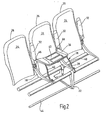
- the first embodiment of a passenger seat row according to the invention according to FIGS. 1 and 2 has at least three seats 10, 12, 14 with a seat frame 16 common to all seats, which has a front transverse member 18 and a rear transverse member 20 parallel to this.
- the two transverse beams 18,20 are formed of light metal or aluminum, in particular in the form of hollow tubes. Furthermore, these are immovably fixed relative to each other by means of seat feet 22, wherein the simpler view is drawn in Fig.2 only one seat base 22.
- the respective seats and carried by the two transverse bars 18,20 and arranged end to the seats seat divider 28 is present.
- the front seat divider 28 has been omitted as seen in the direction of FIGS. 1 and 2.
- the respective seat 10,12,14 is provided with a backrest 30, in the usual and therefore no longer described manner are adjustable in their inclination.
- the respective backrest 30 is shown in its upright position, which corresponds, for example, to the takeoff and landing position of the passenger seat row.
- armrests 32 are present, which are shown in the illustrations according to Figures 1 and 2 in its folded-up position. If the passenger seat row shown, as seen in the direction of Figures 1 and 2, for example, should abut on the left side of a cabin wall, the armrest can account for the leftmost seat to the outside.
- the middle seat 12 of a row of seats between two adjacent seats 10, 14 has a separating part 36 which in a non-use position (see FIG. 1) at least partially in the area of the assignable seat feet 22 for this middle seat 12 and in a position of use (see Fig.2) is at least partially disposed above the seat divider 28. Furthermore, the separating part 36 can be pivoted back and forth between the mentioned positions by means of a pivoting device designated as a whole by 38.
- the partition member 36 is formed in the present embodiments as a table element occupying a substantially vertical ( Figure 1) in the non-use position and a substantially horizontal position relative to the respective seat 12 in the use position ( Figure 2).
- the pivoting device 38 has two pivotally formed pivot lever 40, which are hinged at one end pivotally mounted on the upper side of the front transverse member 18 and pivotally connected at its other end to a longitudinal side of the separating part 36. Is the separating part 36 as shown in FIG. 1 in its non-use position, the two pivot levers 40 extend substantially along the longitudinal side of the separating part 36 and are bent at its upper end at an angle such that preferably under abutment of the cross member 18 for the middle seat 12 is covered. Furthermore, it follows from the illustrations according to FIGS. 1 and 2 that, in the non-use position, the usable table surface 42 of the table element faces away from the seat frame 16 in the direction of the surroundings.
- the table surface 42 may be provided to cover the table surface 42 pointing into the environment in its non-use position by a shell-like cover (not shown) in order to avoid damage or soiling of the table surface 42 in this way.
- the shell-like cover not shown here is pivotally hinged to at least one seat base 22 on the lower crossbar 44. If the separating element 36 in its position of use, then the shell-like cover can be folded back into its covering position, so as not to affect the legroom in the bottom region of the passenger seat row.
- the partition member 36 has on both sides upwardly or rearwardly projecting latching or latching devices 46, the mouth-like peg-like support members overlap as part of the guide webs 34, as soon as the separator 36 is in its position shown in FIG.
- the pertinent support members can also be formed by a guide rod or segments thereof, or run as independent components 34 parallel or coaxial with this rod or its segments. If at least the central pivotable armrests 32 in their folded-up position are an integral part of the backrests 30, such a kind of couch arises from at least three seats 10, 12, 14 arranged in series next to one another, at least in the raised position thereof.
- the non-use position according to FIG. 1 shows the arrangement of the passenger seat row in economy configuration, in which all three seats can be used by seat users. 2, the middle seat 12 is omitted for seat use, and the seat width for the inner and outer seats 10 and 14 is correspondingly increased by the folded, middle armrests 32. Furthermore, the separating part 36 may also have support elements 48 at its opposite ends, which perform the function of the otherwise folded-down armrests 32.
- the middle seat 12 has been shown for the passenger seat row according to the second embodiment and omitted the rest of the seat cushion part 24 for the backrest 30. Furthermore, the armrests 32 are not shown in the illustration.
- the pivot lever 40 of the pivoting device 38 are formed substantially isosceles and overlap in the non-use position of Figure 3, the upper portion of the cross member 18.
- the pertinent solution is without cover, since the usable table surface 42 is not in the non-use position facing the environment, but the seat frame 16 with its seat feet 22.
- the latching and latching device 46 facing the floor in the non-use position is on the seat frame 16 of the respective seat is aufschreibrbar.
- the separating element 36 is pivoted from its non-use position according to Fig.3 counterclockwise in such a partial position according to FIG. 4, that the previously inboard usable table surface 42 the viewer of FIG. 4 facing.
- the latching and latching device 46 is also pivoted upwardly, which is supported by steering lever 52. In that regard, relax the biased springs 50 in the pertinent rotary or pivoting movement for the separating part 36. In a further pivoting movement can then now pivot on the pivot lever 40, the separating part 36 in its position of use according to the illustration of Figure 5 and the locking and latching device 46 then engages again in the assignable guide webs 34 between the seat dividers 28 of the seat 12 a.
- the tripping operation for the partial pivoting movement from the position according to FIG. 3 into the position according to FIG. 4 can be triggered centrally by an operator of a service crew, for example via a spring-loaded pull knob (not shown) on the side facing the aisle side of the respective passenger seat row ,
- the last pivoting movement from the partial position of Figure 4 in the position of use according to Figure 5 can be accomplished in a simple manner by hand.
- lateral support elements 48 on the separating element 36 can serve as armrests.
- the passenger seat row of the invention it is possible to reversibly convert an economy passenger seat row with three seats in a business passenger seat row with two seats and corresponding seat widening, with the conversion of an additional table surface between the two business seats is available.
- the separating part 36 in the form of a table element, there are also other possibilities for designing the separating part 36 differently, for example as a plate-shaped separating element, in order to ensure separation between the business seats of a passenger seat row, thereby increasing the privacy of the seat occupant can contribute with.
Abstract
Description
Die Erfindung betrifft eine Fluggastsitzreihe mit
- a) mindestens drei Sitzen,
- b) einem allen Sitzen gemeinsamen Sitzgestell, das einen vorderen Querholm und einen zu diesem parallel hinteren Querholm aufweist, die relativ zueinander unbeweglich mittels Sitzfüßen fest verbunden sind,
- c) Sitzteilpolster tragenden Polsterträgern,
- d) von den beiden Querholmen getragenen, an den Enden der Sitzreihe und zwischen den Sitzen angeordneten Sitzteilern,
- e) in ihrer Neigungslage einstellbaren Rückenlehnen, die schwenkbar mit den Sitzteilern verbunden sind, und
- f) Armlehnen, vorzugsweise an beiden Enden der Sitzreihe und zwischen den Sitzen, wobei die letztgenannten Armlehnen auf mindestens einer parallel zu den Querholmen verlaufenden und von den zwischen den Sitzen angeordneten Sitzteilern getragenen Führungsstegen schwenkbar angeordnet sind,
- a) at least three seats,
- b) a seat frame which is common to all seats and which has a front transverse bar and a transverse bar which is parallel to the latter and which are immovably fixed relative to one another by means of seat feet,
- c) seat cushion upholstery support,
- d) seat dividers supported by the two transverse struts and arranged at the ends of the row of seats and between the seats;
- e) adjustable in their inclination backrests, which are pivotally connected to the seat dividers, and
- f) armrests, preferably at both ends of the row of seats and between the seats, the latter armrests being pivotally mounted on at least one guide webs extending parallel to the crossbars and supported by the seat dividers arranged between the seats;
Es ist bei einer Fluggastsitzreihe, die von einer Anordnung mit drei Sitzen normaler Breite in eine solche mit zwei Sitzen vergrößerter Breite umwandelbar ist, bekannt (EP 0 322 930 A2), bei einer Umwandlung in zwei Sitze größerer Breite beide sich zwischen den Sitzen befindende Armlehnen aus ihrer Halterung herauszunehmen und aus dem Polster der Rückenlehne des Mittelsitzes eine breite Mittelarmlehne herauszuklappen. Die Umstellung ist deshalb aufwendig. Außerdem wird ein Stauraum für die abnehmbaren Armlehnen benötigt.It is known for a passenger seat row convertible from a three-width normal width arrangement to a two-width increased width seat (EP 0 322 930 A2), when converted into two larger-width seats both armrests located between the seats out remove its holder and fold out of the pad of the backrest of the center seat a wide center armrest. The conversion is therefore complicated. In addition, a storage space for the removable armrests is needed.
Ferner ist es bei einer Fluggastsitzreihe bekannt (EP 0 530 900 A1), vor der Umwandlung von einer Anordnung mit drei Sitzen in eine solche mit zwei Sitzen die beiden mittleren Armlehnen nach hinten zu klappen, so dass sie beim Zusammenschieben der drei Sitze bis zu einer spaltfreien Anlage aneinander hinter der tragenden Struktur der Rückenlehne des Mittelsitzes zu liegen kommen. Für die beiden Sitze vergrößerter Breite wird je eine Armlehne aus dem Polster der Rückenlehne des Mittelsitzes herausgeklappt. Auch hier ist eine Umstellung entsprechend zeitaufwendig.Further, in a passenger seat row (EP 0 530 900 A1), prior to conversion from a three seated to a two seated seat, it is known to fold the two center armrests backwards so that they slide up to one when the three seats are pushed together gap-free system to come to rest behind the supporting structure of the backrest of the center seat. For each of the two seats of increased width, one armrest is folded out of the upholstery of the backrest of the middle seat. Again, a conversion is correspondingly time consuming.
Weiterhin ist eine Fluggastsitzreihe bekannt (EP 0 530 923 A1), bei der für eine Veränderung des Abstandes zwischen den Sitzen die beiden zwischen den Sitzen angeordneten Armlehnen auf je zwei parallel zueinander und zu den Querholmen verlaufenden Stangen als Führungsstege gelagert sind, die von zwischen den Sitzen vorgesehenen Sitzteilern getragen werden. An dem jeweils benachbarten äußeren Sitz ist eine Steuerstange festgelegt, mit deren Hilfe die Armlehne unabhängig von der Größe des einstellbaren Zwischenraumes zwischen den Rückenlehnen auf die Mitte des Zwischenraumes ausgerichtet bleibt. Nachteilig ist bei dieser Lösung, dass sie sich nur für Sitzreihen eignet, bei denen die Anzahl der Sitzplätze nicht verändert wird, sondern nur der Zwischenraum zwischen diesen.Furthermore, a passenger seat row is known (EP 0 530 923 A1), in which for a change in the distance between the seats, the two arranged between the seats armrests are mounted on two parallel to each other and to the crossbars extending rods as guide webs of the between Sitting provided seat dividers are worn. At the respectively adjacent outer seat, a control rod is fixed, with the help of which the armrest remains independent of the size of the adjustable gap between the backrests aligned with the center of the gap. The disadvantage of this solution is that it is only suitable for rows of seats in which the number of seats is not changed, but only the space between them.
Bei der bekannten Fluggastsitzreihe der eingangs genannten Art (EP 0 530 920 A1) sind die zwischen den Sitzen vorgesehenen Armlehnen ebenfalls auf sich in Längsrichtung der Querholme erstreckenden Führungsstegen gelagert. Ihre Verschiebung auf diesen stangenartigen Führungsstegen Führungsstangen erfolgt jedoch mittels je eines flexiblen Zuges, der einerseits mit der Armlehne und andererseits mit einem Längsträger verbunden ist, welcher bei einer Umwandlung der Sitzreihe von einer solchen mit drei Sitzen normaler Breite in eine Sitzreihe mit zwei Sitzen größerer Breite und umgekehrt zwangsweise in Sitzquerrichtung verschoben wird. Bei dieser Fluggastsitzreihe ist nicht nur der Kraftaufwand für eine Sitzverschiebung relativ groß; nachteilig ist auch, dass die Lagerung der Mittelarmlehne konstruktiv aufwendig, relativ schwer und kostenintensiv ist.In the known passenger seat row of the type mentioned (EP 0 530 920 A1) provided between the seats armrests are also on extending in the longitudinal direction of the transverse bars guide webs stored. Their displacement on these rod-like guide webs guide rods, however, by means of a respective flexible train, which is connected on the one hand to the armrest and on the other hand with a longitudinal beam, which in a conversion of the row of seats from one with three seats of normal width in a row of seats with two seats of greater width and vice versa forcibly moved in the seat transverse direction. In this passenger seat row is not only the force required for a seat displacement relatively large; Another disadvantage is that the storage of the center armrest is structurally complex, relatively heavy and expensive.
Demgemäß wurde bei einer bekannten Fluggastsitzreihe (DE 43 29 452 C2) bereits vorgeschlagen, unter Vermeidung zusätzlicher Bauteile für die Lagerung der Armlehnen diese an einer rohrartigen Führungsstange anzuordnen, über die die einzelnen Rückenlehnen mit den zwischen den Sitzen angeordneten Sitzteilern verbunden sind. Obwohl das bei der bekannten Lösung eingesetzte Hebelgetriebe für die Verschiebung der Armlehnen einen sehr reibungsarmen Antrieb gewährleistet, so dass der Kraftaufwand für die Verschiebung der Sitze und Armlehnen so gering gehalten werden kann wie möglich, ist der dahingehende Umstellaufwand immer noch als hoch einzustufen und trotz der erreichten Verbesserungen ist die bekannte Lösung kostenintensiv in der Realisierung und schwer, was bekanntermaßen im Bereich der Luftfahrt als sehr nachteilig angesehen wird, wo man jedes Gramm zur Erhöhung der Nutzlast einsparen möchte.Accordingly, in a known passenger seat row (DE 43 29 452 C2) has already been proposed, while avoiding additional components for the storage of the armrests to arrange them on a tubular guide rod over which the individual backrests are connected to the arranged between the seats seat dividers. Although the lever mechanism used in the known solution for the displacement of the armrests ensures a very low-friction drive, so that the force required for the displacement of the seats and armrests can be kept as low as possible, the pertinent Umstellaufwand is still classified as high and despite the achieved improvements, the known solution is costly to implement and difficult, which is known to be very disadvantageous in the aviation industry, where you want to save every gram to increase the payload.
Durch die EP-A-0 385 861 ist eine gattungsgemäße Fluggastsitzreihe mit mindestens drei Sitzen bekannt. Der mittlere Sitz ist gegenüber den benachbarten Sitzen mittels zweier Armlehnen separiert, die jeweils über ein Parallelogrammgestänge voneinander weg in eine äußere Position bringbar sind, was die Sitzbenutzung des mittleren Sitzes erlaubt, sowie umgekehrt in Richtung aufeinander zu in eine innere Position bringbar sind, bei der sich die Sitzbreite für die benachbarten Sitze erhöht. Bei der bekannten Lösung ist unterhalb der Sitzteilpolsterung für den mittleren Sitz ein als Tischteil vorgesehenes Trennteil in einer Nichtgebrauchsstellung in einer horizontalen Lage gegenüber dem mittleren Sitz oberhalb der zuordenbaren Sitzfüße für diesen mittleren Sitz angeordnet, das mittels einer Schwenkhebeleinrichtung in eine gleichfalls horizontal verlaufende Gebrauchsstellung nach oben ausschwenkbar ist, um dergestalt die Sitzaufteilung zwischen den äußeren dann verbreiterten Sitzen mit vorzunehmen. Bei der bekannten Lösung wird das dahingehende, als Tischelement dienende Trennteil in der Gebrauchsstellung auf den beiden benachbarten, aufeinander zu geschwenkten Armlehnen aufgesetzt und eine Verstaumöglichkeit in die Nichtgebrauchsstellung ist möglich, sobald die beiden Armlehnen voneinander weggeschwenkt ihre äußere Position einnehmen. Bei der bekannten Lösung ist wiederum ein entsprechender Umstellaufwand zu betreiben bedingt durch die Paralleleinstellung der Armlehnen und die jeweilige Umbaumaßnahme im Bereich des Sitzteilpolsters für den mittleren Sitz, sobald das Trennteil für den Umbau einer Dreier-Sitzreihe in eine Zweier-Sitzreihe benötigt wird.From EP-A-0 385 861 a generic passenger seat row with at least three seats is known. The middle seat is separated from the adjacent seats by means of two armrests, which can be brought away from each other via a Parallelogrammgestänge away in an outer position, which allows the seat use of the middle seat, and vice versa towards each other in an inner position can be brought, in the the seat width increases for the adjacent seats. In the known solution is below the seat part padding for the middle seat provided as a table part separator in a non-use position in a horizontal position relative to the middle seat above the assignable seat feet for this middle seat, which is swung by means of a pivot lever device in a likewise horizontally extending position of use up to To make the seat division between the outer then widened seats. In the known solution, the pertinent, serving as a table element separating part is placed in the position of use on the two adjacent, mutually pivoted armrests and a stowage possibility in the non-use position is possible as soon as the two armrests swung away from each other take their outer position. In the known solution, in turn, a corresponding Umstellungsaufwand to operate due to the parallel setting of the armrests and the respective conversion measure in the area of the seat part cushion for the middle seat as soon as the partition is needed for the conversion of a three-row seat in a two-seater row.
Ausgehend von diesem Stand der Technik liegt daher der Erfindung die Aufgabe zugrunde, eine Fluggastsitzreihe zu schaffen, die trotz einer einfachen und gewichtsarmen Konstruktion eine Umrüstung von Sitzen einer bestimmten Breite auf Sitze mit einer anderen nutzbaren Breite bei verkürztem Zeitaufwand ermöglicht. Eine dahingehende Aufgabe löst eine Fluggastsitzreihe mit den Merkmalen des Patentanspruches 1 in seiner Gesamtheit.Based on this prior art, therefore, the present invention seeks to provide a passenger seat row, which allows despite a simple and low-weight construction, a conversion of seats of a certain width on seats with a different usable width with a reduced amount of time. A pertinent task solves a passenger seat series with the features of claim 1 in its entirety.
Dadurch, dass gemäß dem kennzeichnenden Teil des Patentanspruches 1 in der Nichtgebrauchsstellung das Trennteil im Bereich der zuordenbaren Sitzfüße für diesen mittleren Sitz angeordnet ist und eine im wesentlichen vertikale Lage gegenüber dem jeweiligen Sitz einnimmt, läßt sich eine sog. drei Sitze umfassende Economy-Fluggastsitzreihe, wie im Stand der Technik aufgezeigt, in eine zweisitzige Business-Fluggastsitzreihe umwandeln mit einer entsprechenden Sitzverbreiterung, jedoch mit einer gegenüber der bekannten Lösung vereinfachten und gewichtsarmen Konstruktion sowie mit einer vereinfachten Umrüstung mit verkürztem Zeitaufwand.Characterized in that according to the characterizing part of claim 1 in the non-use position, the separating part is arranged in the region of the assignable seat feet for this middle seat and occupies a substantially vertical position relative to the respective seat, can be a so-called. Three seats comprehensive economy passenger seat row, As shown in the prior art, to convert into a two-seat business passenger seats with a corresponding seat widening, but with a comparison with the known solution simplified and low-weight construction and with a simplified conversion with a reduced amount of time.
Zunächst wird durch Hochklappen der mittleren Armlehnen innerhalb der Fluggastsitzreihe erreicht, dass es zu einer faktisch nutzbaren Sitzverbreiterung der beiden äußeren Sitze kommt und der mittlere Sitz innerhalb der Fluggastsitzreihe wird dem Grunde nach dadurch belegt, dass das Trennteil aus der skizzierten Nichtgebrauchsstellung in die Gebrauchsstellung hochgeschwenkt die nutzbare Sitzfläche dieses mittleren Sitzes überdeckt und insoweit einem potentiellen Sitzbenutzer (Fluggast) die Möglichkeit nimmt, diesen mittleren Sitz als Sitzplatz zu nutzen. Ist das Trennteil in seiner Gebrauchsstellung, also oberhalb der Sitzfläche des mittleren Sitzes arretiert, sind die jeweiligen Sitzbenutzer an den äußeren Enden der Fluggastsitzreihe im jeweiligen Sitz aufgenommen, räumlich deutlich voneinander separiert, was bei diesen als subjektiven Eindruck ein großzügiges Raumangebot entstehen läßt, was im Rahmen der Business - Class gewünscht ist. Neben der bereits angesprochenen faktischen Sitzverbreiterung für die beiden äu-ßeren Sitze einer Fluggastsitzreihe kommt insoweit über das Trennteil in der Gebrauchsstellung der eigenständig nutzbare verbreiterte Sitzbereich besonders zur Geltung und in Abhängigkeit der Ausgestaltung des Trennteils kann dann dieses von den gegenüberliegend sitzenden Sitzbenutzern gleichermaßen benutzt werden.First, it is achieved by folding up the middle armrests within the passenger seat row, that there is a virtually usable seat widening of the two outer seats and the middle seat within the passenger seat row is basically occupied by the fact that the partition from the outlined non-use position swung into the use position the usable seat of this middle seat covers and insofar as a potential seat occupant (passenger) takes the opportunity to use this middle seat as a seat. If the partition is locked in its position of use, ie above the seat of the middle seat, the respective seat occupants are accommodated at the outer ends of the passenger seat row in the respective seat, spatially clearly separated from each other, which creates a generous amount of space in these as a subjective impression, which in Business Class is desired. In addition to the already mentioned factual seat widening for the two outer ßere seats a passenger seat row comes so far on the partition in the position of use of the independently usable widened seating area particularly to the validity and depending on the design of the partition then this can be used equally by the seated seat users sitting opposite.
In der praktischen Realisierung wird dabei vor dem Flug über eine entsprechende Service - Mannschaft bei Bedarf die Economy - Fluggastsitzreihe in die Business - Fluggastsitzreihe umgewandelt, so dass bei Betreten des Flugzeuges der jeweilige Sitzbenutzer in der Business - Class die bereits eingestellte Sitzverbreiterung vorfindet und hier selbst nicht mehr tätig werden muß. Umgekehrt schwenkt die angesprochene Service - Mannschaft das Trennteil zurück in seine Nichtgebrauchsstellung, sofern die Business - Fluggastsitzreihe in eine Economy - Fluggastsitzreihe mit drei nebeneinanderliegenden Sitzen umgebaut werden soll. Die erfindungsgemäße Fluggastsitzreihe braucht nicht auf Sitzanordnungen mit drei nebeneinander angeordneten Sitzen eingeschränkt zu sein, sondern die Sitzreihe kann hier mehr nebeneinanderliegende Sitze umfassen, wobei dann vorzugsweise in alternierender Reihenfolge zwischen jedem Sitz, der als Business - Sitz vorgesehen ist, ein Sitz mit dem Trennteil vorhanden ist. Es ist aber auch möglich, über zwei nebeneinander angeordnete Sitze mit Trennteilen eine mittlere Trennung über zwei Sitze einer Viererreihe vorzunehmen, wobei dann wiederum die beiden äußersten Sitze den Business - Sitz mit verbreiterter Sitzfläche ausbilden.In the practical realization, the Economy Passenger Seat Row is converted into the Business Passenger Seat Row prior to the flight via an appropriate service team, so that upon entering the aircraft the respective seat occupant in the Business Class finds the already set seat widening and here himself no longer has to act. Conversely, if the business passenger seat row is to be converted into an economy passenger seat row with three adjacent seats, the addressed service crew will return the divider to its inoperative position. The passenger seat row according to the invention does not need to be limited to seat arrangements with three seats arranged side by side, but the row of seats may here comprise more juxtaposed seats, then preferably in alternating order between each seat, which is provided as a business seat, a seat with the separating part is. But it is also possible to make two separate seats with dividing parts a middle separation over two seats of a row of four, in turn, then the two outermost seats form the business - seat with widened seat.
Bei einer besonders bevorzugten Ausführungsform der erfindungsgemäßen Fluggastsitzreihe ist das Trennteil ein Tischelement. Auf diese Art und Weise steht dem Business -Sitzbenutzer vermehrt für seine Verwendung Tischfläche zur Verfügung.In a particularly preferred embodiment of the passenger seat row according to the invention, the separating part is a table element. In this way, the business seat user is increasingly available for his use of table surface.
Bei einer weiteren bevorzugten Ausführungsform der erfindungsgemäßen Fluggastsitzreihe weist die Schwenkeinrichtung mindestens einen schwenkbar angeordneten, winklig ausgebildeten Schwenkhebel auf, der jeweils mit einem Ende schwenkbar am Sitzgestell oder Teilen desselben angelenkt ist und mit seinem anderen Ende schwenkbar an Teilen des Trennteils. Die dahingehende Schwenkeinrichtung mit jeweils winklig ausgebildetem Schwenkhebel erlaubt auf besonders platzsparende Art und Weise, den Schwenkvorgang für das Trennteil vorzunehmen.In a further preferred embodiment of the passenger seat row according to the invention, the pivot means at least one pivotally mounted, angularly formed pivot lever, which is pivotally hinged at one end to the seat frame or parts thereof and pivotally connected at its other end to parts of the separating part. The pertinent pivoting device, each with an angle formed pivot lever allowed in a particularly space-saving manner to make the pivoting operation for the separator.
Bei einer anders gearteten, bevorzugten Ausführungsform der erfindungsgemäßen Fluggastsitzreihe kann aber die Schwenkeinrichtung auch aus einem Parallelogrammgestänge bestehen, dessen Lenker mit ihrem oberen Ende in der Nichtgebrauchsstellung nach vorne und in der Gebrauchsstellung ansonsten nach hinten weisen. Auch insoweit läßt sich platzsparend das Trennteil von seiner Nichtgebrauchsstellung in die Gebrauchsstellung und umgekehrt verschwenken.In a different kind, preferred embodiment of the passenger seat row according to the invention but the pivoting means may also consist of a parallelogram, the handlebars with their upper end in the non-use position to the front and in the position of use otherwise point to the rear. Also in this respect can save space to move the separator from its non-use position to the use position and vice versa.
Alternativ kann bei einer anders gearteten Fluggastsitzreihe auch vorgesehen sein, das Trennteil unterhalb der Sitzfläche, insbesondere des mittleren Sitzes, in einer Aufnahme zu bevorraten, um es dann von dort zu entnehmen und in der Gebrauchsstellung auf den mittleren Sitz verrastend aufzusetzen. Die genannten erfindungsgemäßen Schwenklösungen haben jedoch den Vorteil, dass man den Einbauraum unter der Sitzfläche nicht benötigt, so dass dergestalt dort eine für den Notfall vorgesehene Schwimmweste od. dgl. gut zugänglich bevorratet werden kann.Alternatively, it may also be provided in a passenger seat row of a different type, to store the separating part below the seat, in particular of the middle seat, in a receptacle, in order to remove it from there and place it latching in the position of use on the middle seat. However, the aforementioned pivoting solutions according to the invention have the advantage that one does not need the installation space under the seat, so that there od a life jacket provided for emergency. The like. Can be stored well accessible.
Bei einer weiteren, bevorzugten Ausführungsform der erfindungsgemäßen Fluggastsitzreihe weist in der Nichtgebrauchsstellung die nutzbare Tischfläche des Tischelementes vom Sitzgestell weg in Richtung Umgebung oder in Richtung Sitzgestell. Ferner ist vorzugsweise vorgesehen, dass bei der in die Umgebung weisenden Tischfläche diese in der Nichtgebrauchsstellung von einer schalenartigen Abdeckung abgedeckt ist, die schwenkbar an mindestens einem Sitzfuß angelenkt ist. Dergestalt läßt sich die nutzbare Tischfläche vor Beschädigungen und Verschmutzungen im Beinraum schützen. Nach Freigabe des Tischelementes wird die schalenartige Abdeckung dann wieder in ihre Grundstellung zurückverschwenkt, so dass dergestalt der frei nutzbare Beinraum für den jeweiligen Business - Sitzbenutzer nicht eingeschränkt ist.In a further preferred embodiment of the passenger seat row of the invention, in the non-use position, the usable table surface of the table element away from the seat frame in the direction of the environment or towards the seat frame. Furthermore, it is preferably provided that in the table surface facing into the environment, this is covered in the non-use position of a shell-like cover which is pivotally hinged to at least one seat leg. In this way, the usable table surface can be protected from damage and dirt in the legroom. After release of the table element, the shell-like cover is then pivoted back into its basic position, so that the freely usable leg space for the respective business seat user is not restricted in this way.
Bei einer weiteren, besonders bevorzugten Ausführungsform der erfindungsgemäßen Fluggastsitzreihe ist das Trennteil in der Gebrauchsstellung mit einer Rast- oder Einklinkeinrichtung mit feststehenden Teilen des zuordenbaren Sitzes, insbesondere des jeweiligen Führungssteges, verrastbar bzw. einklinkbar, an der die zuordenbare Armlehne schwenkbar angeordnet ist. Ferner besteht die Möglichkeit des Einrastens oder Einklinkens an sog. Auflageteilen des Sitzes, die parallel oder koaxial zum jeweiligen Führungssteg der Armlehne verlaufen. Hierdurch ist das Trennteil, insbesondere in Form des Tischelementes, mit feststehenden Baukomponenten des Sitzes in der Gebrauchsstellung verbunden, was eine weitgehende ruhige und sichere Fixierung des Trennteils gewährleistet. Demgemäß gibt das Trennteil in der Gebrauchsstellung auch nicht nach, beispielsweise wenn ein Sitzbenutzer bei Verlassen seines Sitzes sich an dem Trennteil entsprechend abstützen sollte.In a further, particularly preferred embodiment of the passenger seat row according to the invention, the separating part in the position of use with a latching or latching with fixed parts of the assignable seat, in particular the respective guide bar, latched or latched to which the assignable armrest is pivotally mounted. Furthermore, there is the possibility of latching or latching on so-called. Pad members of the seat, which run parallel or coaxial with the respective guide web of the armrest. As a result, the separating part, in particular in the form of the table element, connected to fixed structural components of the seat in the use position, which ensures a largely quiet and secure fixation of the separating part. Accordingly, the partition also does not yield in the position of use, for example when a seat occupant should be appropriately supported on the partition when leaving his seat.
Bei einer weiteren, bevorzugten Ausführungsform der erfindungsgemäßen Fluggastsitzreihe sind zumindest die mittleren schwenkbaren Armlehnen in ihrer hochgeklappten Stellung integraler Bestandteil einer dann couchartigen Rückenlehne, gebildet aus mindestens drei in Reihe nebeneinander angeordneten Sitzen, zumindest sofern die einzelnen Rückenlehnen in ihrer aufrechten Neigungseinstellage sind. Bei der Erweiterung der Sitzfläche ist mithin ein Business - Sitzbenutzer durch die hochgeklappten Armlehnen in seinem Sitzkomfort nicht gestört, wobei vorzugsweise vorgesehen ist, dass die Armlehnen an ihrer Unterseite eine entsprechende Polsterung aufweisen.In a further, preferred embodiment of the passenger seat row according to the invention, at least the central pivotable armrests in their folded-up position form an integral part of a then couch-like Backrest, formed of at least three seats arranged in series next to one another, at least if the individual backrests are in their upright inclination adjustment position. When expanding the seat, a business seat occupant is therefore not disturbed by the folded-up armrests in terms of seating comfort, wherein it is preferably provided that the armrests have corresponding upholstery on their underside.
Bei einer weiteren, bevorzugten Ausführungsform der erfindungsgemäßen Fluggastsitzreihe ist mittels mindestens eines Kraftspeichers (Zugfeder) das Trennteil automatisch von seiner Nichtgebrauchsstellung nach Auslösen oder Betätigen zumindest teilweise in Richtung seiner Gebrauchsstellung gebracht, was den Kräfteaufwand für die Service - Mannschaft reduzieren hilft und im übrigen den Montagekomfort erhöht, da dann das Trennteil nicht mehr aus einer untersten Nichtgebrauchsposition erst noch angehoben werden muß.In a further preferred embodiment of the passenger seat row according to the invention, the separating part is automatically brought from its non-use position after triggering or actuation at least partially in the direction of its use position by means of at least one force accumulator, which helps to reduce the effort required for the service team and, moreover, the ease of assembly increased, since then the separator no longer needs to be raised from a lowermost non-use position.
Vorzugsweise ist des weiteren vorgesehen, dass das Trennteil an seinen gegenüberliegenden Enden, den benachbarten Sitzen eines mittleren Sitzes zugewandt, in der Art von Armlehnen Aufstützelemente aufweist. Somit steht dann dem Business - Sitzbenutzer ein Teil des Trennteils zur Komforterhöhung als Armlehne zur Verfügung.Preferably, it is further provided that the separating part facing at its opposite ends, the adjacent seats of a middle seat, in the manner of armrests supporting elements. As a result, the business seat user has access to a part of the partition to increase comfort as an armrest.
Im folgenden wird die erfindungsgemäße Fluggastsitzreihe anhand zweier Ausführungsbeispiele nach der Zeichnung näher erläutert. Dabei zeigen in prinzipieller und nicht maßstäblicher Darstellung sowie in perspektivischer Ansicht die
- Fig.1 und 2
- eine erste Ausführungsform der erfindungsgemäßen Fluggastsitzreihe mit einem Trennteil, einmal in der Nichtgebrauchsstellung, einmal in der Gebrauchsstellung,
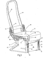
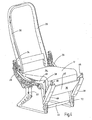
- Fig.3, 4 und 5
- in verschiedenen Stellungen die wesentlichen Komponenten des mittleren Sitzes einer zweiten Ausführungsform einer Fluggastsitzreihe mit dem Trennteil in verschiedenen Stellungen.
- Fig.1 and 2
- A first embodiment of the passenger seat row according to the invention with a separating part, once in the non-use position, once in the position of use,
- 3, 4 and 5
- in various positions, the essential components of the middle seat of a second embodiment of a passenger seat row with the separator in different positions.
Die erste Ausführungsform einer erfindungsgemäßen Fluggastsitzreihe nach den Fig.1 und 2 weist mindestens drei Sitze 10,12,14 auf mit einem allen Sitzen gemeinsamen Sitzgestell 16, das einen vorderen Querholm 18 und einen zu diesem parallelen hinteren Querholm 20 aufweist. Die beiden Querholme 18,20 sind aus Leichtmetall oder Aluminium, insbesondere in der Art von Hohlrohren ausgebildet. Ferner sind diese relativ zueinander unbeweglich mittels Sitzfüßen 22 fest verbunden, wobei der einfacheren Darstellung wegen in der Fig.2 nur ein Sitzfuß 22 eingezeichnet ist. Ferner weist die Fluggastsitzreihe Sitzteilpolster 24 tragende Polsterträger 26 auf, wobei der verbesserten Darstellung wegen wiederum in den Fig.1 und 2 die Sitzteilpolster des eigentlichen Sitzteils nicht dargestellt sind. Des weiteren sind zwischen den jeweiligen Sitzen und von den beiden Querholmen 18,20 getragen sowie endseitig an den Sitzen angeordnet Sitzteiler 28 vorhanden. Der einfacheren Darstellung wegen wurde in Blickrichtung auf die Fig.1 und 2 gesehen der vorderste Sitzteiler 28 weggelassen. Der jeweilige Sitz 10,12,14 ist mit einer Rückenlehne 30 versehen, die in üblicher und daher nicht mehr näher beschriebener Art und Weise in ihrer Neigung einstellbar sind. Gemäß der Darstellung nach den Fig.1 und 2 ist die jeweilige Rückenlehne 30 in ihrer aufrechten Stellung gezeigt, die beispielsweise der Start- und Landeposition der Fluggastsitzreihe entspricht. Des weiteren sind Armlehnen 32 vorhanden, die in den Darstellungen nach den Fig.1 und 2 in ihrer hochgeklappten Stellung wiedergegeben sind. Sofern die gezeigte Fluggastsitzreihe in Blickrichtung auf die Fig.1 und 2 gesehen beispielsweise linksseitig an eine Kabinenwand anstoßen sollte, kann auch für den äußerst linken Sitz nach außen hin die Armlehne entfallen. Vorzugsweise erfolgt die Schwenkmöglichkeit für die einzelnen Armlehnen 32 entlang einer von den Sitzteilern 28 getragenen Führungsstange, wobei die Führungsstange in Führungsstege 34 unterteilt ist, so dass jeder Armlehne 32 ein eigenständiges Schwenksegment zugeordnet ist.The first embodiment of a passenger seat row according to the invention according to FIGS. 1 and 2 has at least three
Gemäß den Darstellungen nach den Fig.1 und 2 weist der mittlere Sitz 12 einer Sitzreihe zwischen zwei benachbarten Sitzen 10,14 ein Trennteil 36 auf, das in einer Nichtgebrauchsstellung (vgl. Fig.1) zumindest teilweise im Bereich der zuordenbaren Sitzfüße 22 für diesen mittleren Sitz 12 und in einer Gebrauchsstellung (vgl. Fig.2) zumindest teilweise oberhalb der Sitzteiler 28 angeordnet ist. Ferner ist das Trennteil 36 mittels einer als Ganzes mit 38 bezeichneten Schwenkeinrichtung zwischen den genannten Stellungen hin- und herschwenkbar. Das Trennteil 36 ist in den vorliegenden Ausführungsbeispielen als Tischelement ausgebildet, das in der Nichtgebrauchsstellung eine im wesentlichen vertikale (Fig.1) und in der Gebrauchsstellung (Fig.2) eine im wesentlichen horizontale Lage gegenüber dem jeweiligen Sitz 12 einnimmt. Die Schwenkeinrichtung 38 weist zwei winklig ausgebildete Schwenkhebel 40 auf, die mit ihrem einen Ende schwenkbar an der Oberseite des vorderen Querholmes 18 angelenkt sind und mit ihrem anderen Ende schwenkbar an einer Längsseite des Trennteils 36. Ist das Trennteil 36 gemäß der Darstellung nach der Fig.1 in seiner Nichtgebrauchsstellung, verlaufen die beiden Schwenkhebel 40 im wesentlichen entlang der Längsseite des Trennteils 36 und sind an ihrem oberen Ende winklig derart umgebogen, dass vorzugsweise unter Anlage der Querholm 18 für den mittleren Sitz 12 überfaßt ist. Des weiteren ergibt sich aus den Darstellungen nach den Fig.1 und 2, dass in der Nichtgebrauchsstellung die nutzbare Tischfläche 42 des Tischelementes vom Sitzgestell 16 weg in Richtung Umgebung weist. Insoweit kann vorgesehen sein, die in die Umgebung weisende Tischfläche 42 in ihrer Nichtgebrauchsstellung von einer schalenartigen Abdeckung (nicht dargestellt) abzudecken, um dergestalt Beschädigungen oder Verschmutzungen der Tischfläche 42 zu vermeiden. Vorzugsweise ist dabei die nicht näher dargestellte schalenartige Abdeckung schwenkbar an mindestens einem Sitzfuß 22 über die untere Querstange 44 angelenkt. Ist das Trennelement 36 in seiner Gebrauchsstellung, kann dann die schalenartige Abdeckung wieder in ihre abdeckende Stellung hochgeklappt werden, um dergestalt den Beinraum im Bodenbereich der Fluggastsitzreihe nicht zu beeinträchtigen.1 and 2, the
Das Trennteil 36 weist beidseitig nach oben oder hinten vorstehende Rast- oder Einklinkeinrichtungen 46 auf, die maulartig zapfenartige Auflageteile als Bestandteil der Führungsstege 34 übergreifen, sobald das Trennteil 36 in seiner in der Fig.2 dargestellten Gebrauchsstellung ist. Die dahingehenden Auflageteile können auch durch eine Führungsstange oder Segmente derselben gebildet sein oder als eigenständige Bauteile 34 parallel oder koaxial zu dieser Stange oder deren Segmente verlaufen. Sofern zumindest die mittleren schwenkbaren Armlehnen 32 in ihrer hochgeklappten Stellung integraler Bestandteil der Rückenlehnen 30 sind, entsteht dergestalt zumindest in der hochgestellten Stellung derselben eine Art Couch aus mindestens drei in Reihe nebeneinander angeordneten Sitzen 10,12,14.The
Die Nichtgebrauchsstellung nach der Fig.1 zeigt die Anordnung der Fluggastsitzreihe in Economy - Konfiguration, bei der alle drei Sitze für Sitzbenutzer nutzbar sind. Befindet sich das Trennelement 36 gemäß der Darstellung nach der Fig.2 in seiner Gebrauchsstellung, entfällt der mittlere Sitz 12 für eine Sitzbenutzung und durch die hochgeklappten, mittleren Armlehnen 32 ist die Sitzbreite für den inneren und äußeren Sitz 10 bzw. 14 entsprechend erhöht. Des weiteren kann das Trennteil 36 an seinen gegenüberliegenden Enden auch Stützelemente 48 aufweisen, die die Funktion der sonst üblichen heruntergeklappten Armlehnen 32 wahrnehmen.The non-use position according to FIG. 1 shows the arrangement of the passenger seat row in economy configuration, in which all three seats can be used by seat users. 2, the
Sofern die weitere Ausführungsform nach den Fig.3ff dem Ausführungsbeispiel nach den Fig.1 und 2 entspricht, werden insoweit für die zweite Ausführungsform für dieselben Bauelemente und Baugruppen dieselben Bezugszeichen verwendet wie für das erste Ausführungsbeispiel. Insoweit gelten dann die bisher getroffenen Ausführungen auch für die weitere Ausführungsform nach den Fig. 3 bis 5.If the further embodiment according to FIG. 3 corresponds to the exemplary embodiment according to FIGS. 1 and 2, the same reference numerals are used for the same embodiment for the same embodiment as for the first embodiment for the second embodiment. In that regard, then apply the previously made statements for the further embodiment of FIGS. 3 to 5.
Der besseren Darstellung wegen wurde für die Fluggastsitzreihe nach der zweiten Ausführungsform nur noch der mittlere Sitz 12 dargestellt und im übrigen das Sitzteilpolster 24 für die Rückenlehne 30 weggelassen. Ferner sind die Armlehnen 32 in der Darstellung nicht gezeigt. Die Schwenkhebel 40 der Schwenkeinrichtung 38 sind im wesentlichen gleichschenklig ausgebildet und übergreifen in der Nichtgebrauchsstellung nach der Fig.3 den oberen Bereich des Querholmes 18. Die dahingehende Lösung kommt ohne Abdeckung aus, da die nutzbare Tischfläche 42 in der Nichtgebrauchsstellung nicht der Umgebung zugewandt ist, sondern dem Sitzgestell 16 mit seinen Sitzfüßen 22. Ein weiterer Unterschied besteht darin, dass die Rast- und Einklinkeinrichtung 46 in der Nichtgebrauchsstellung dem Boden zugewandt ist, auf dem über das Sitzgestell 16 der jeweilige Sitz aufständerbar ist.For better illustration, only the
Mittels eines Kraftspeichers in Form zweier Zugfedern 50 wird bei Auslösung das Trennelement 36 aus seiner Nichtgebrauchsstellung nach der Fig.3 entgegen dem Uhrzeigersinn derart in eine Teilstellung nach der Fig. 4 geschwenkt, dass die bisher innen liegende nutzbare Tischfläche 42 dem Betrachter nach der Fig.4 zugewandt erscheint. Ferner ist die Rast- und Einklinkeinrichtung 46 gleichfalls nach oben verschwenkt, was durch Lenkhebel 52 unterstützt ist. Insoweit entspannen sich die vorgespannten Zugfedern 50 bei der dahingehenden Dreh- oder Schwenkbewegung für das Trennteil 36. In einer weiteren Schwenkbewegung läßt sich dann nunmehr über die Schwenkhebel 40 das Trennteil 36 in seine Gebrauchsstellung gemäß der Darstellung nach der Fig.5 verschwenken und die Rast- und Einklinkeinrichtung 46 greift dann wiederum in die zuordenbaren Führungsstege 34 zwischen den Sitzteilern 28 des Sitzes 12 ein. Der Auslösevorgang für die Teilschwenkbewegung von Position nach der Fig.3 in die Position nach der Fig.4 kann von einer Bedienperson einer Service - Mannschaft zentral ausgelöst werden, beispielsweise über einen federbelasteten Zugknopf (nicht dargestellt) auf der der Gangseite der jeweiligen Fluggastsitzreihe zugewandten Seite. Die letzte Schwenkbewegung von der Teilstellung nach der Fig.4 in die Gebrauchsstellung nach der Fig.5 läßt sich in einfacher Weise von Hand bewerkstelligen. Auch bei dieser Lösung können seitliche Aufstützelemente 48 am Trennelement 36 als Armlehnen dienen. Das Zurückschwenken von der Gebrauchsstellung nach der Fig.5 in die Nichtgebrauchsstellung nach der Fig.3 erfolgt wiederum in umgekehrter Weise, wobei mit Erreichen der Nichtgebrauchsstellung die Zugfedern 50 für einen erneuten automatischen Auslösevorgang gespannt werden.By means of an energy storage device in the form of two tension springs 50, the separating
Mit der erfindungsgemäßen Fluggastsitzreihe ist es möglich, eine Economy-Fluggastsitzreihe mit drei Sitzen in eine Business - Fluggastsitzreihe mit zwei Sitzen und entsprechender Sitzverbreiterung reversibel umzubauen, wobei mit der Umwandlung eine zusätzliche Tischfläche zwischen den beiden Business - Sitzen zur Verfügung steht. Anstelle der Ausbildung des Trennteils 36 in Form eines Tischelementes bestehen hier gegebenenfalls auch noch andere Möglichkeiten, das Trennteil 36 anders auszugestalten, beispielsweise als plattenförmiges Trennelement, um dergestalt eine Separierung zwischen den Business - Sitzen einer Fluggastsitzreihe zu gewährleisten, was zur Erhöhung der Privatsphäre des Sitzbenutzers mit beitragen kann.With the passenger seat row of the invention, it is possible to reversibly convert an economy passenger seat row with three seats in a business passenger seat row with two seats and corresponding seat widening, with the conversion of an additional table surface between the two business seats is available. Instead of the formation of the separating
Claims (10)
- Airplane passenger seat row witha) at least three seats (10, 12, 14),b) a seat frame (16) common to all three seats, comprising a front transverse beam (18) and a rear transverse beam (20) extending parallel to the same, the same being firmly connected in relation to each other via non-moveable seat legs (22),c) upholstery supports (26) supporting upholstered seat parts (24),d) seat parts (28) located at the ends of the seat row and between the seats by both transverse beams (18, 20),e) back rests (30), the position of which is reclinable, tiltably connected with the seat parts (28); andf) arm rests (32), preferably at both ends of the seat row and between the seats (10, 12, 14), whereby the latter arm rests (32) are tiltably located on at least one guide rail (34) extending parallel to the transverse beams (18, 20) and supported by the seat parts (10, 12, 14) located between the seat dividers (28),whereby a middle seat (12) of a seat row comprises a separating part (36) between adjacent seats (10, 14), which can be positioned in a non-usage position and in a usage position above the seat parts (28) in a substantially horizontal position in relation to the relevant seat, and whereby the separating part (36) can be moved between the said positions by means of a tiling means (38), characterised in that the separating part (36) covers the usable seat surface of the middle seat (12) in the usage position, and can be tilted into the area of the associated seat legs (22) of the middle seat (12) in the non-usage position, and takes up a substantially vertical position in relation to the relevant seat (12) in this position.
- Airplane passenger seat row according to Claim 1, characterised in that the separating part (36) consists of a table element.
- Airplane passenger seat row according to Claim 1 or 2, characterised in that the tilting means (38) comprises at least one tiltably arranged angled tilt lever (40), the same being tiltably affixed to the seat frame or parts (18) of the same with its one end, and tiltably affixed to parts of the separating part (36) with its other end.
- Airplane passenger seat row according to Claim 1 or 2, characterised in that the tilting means (38) comprises a parallelogram frame, the steering of which faces towards the front with its upper end in the non-usage position, and towards the rear in the usage position.
- Airplane passenger seat row according to one of the Claims 2 to 4, characterised in that the usable table surface (42) of the table element faces away from the seat frame (16) in the direction of its surroundings of in the direction of the seat frame (16) in the non-usage position.
- Airplane passenger seat row according to Claim 5, characterised in that the table surface (42) facing towards its surroundings is covered by means of a bowl-shaped cover in its non-usage position, the same being tiltably affixed to at least one seat leg (22).
- Airplane passenger seat row according to one of the Claims 1 to 6, characterised in that the separating part (36) can be arrested, i.e. snapped into stationary parts of the associated seat in the usage position by means of an arresting or snap-in means (46), in particular of the relevant guide rod (34), on which the associated arm rest (32) is tiltably affixed, or on upholstery parts of the seat extending parallel or coaxially in relation to the relevant guide rod (34).
- Airplane passenger seat row according to one of the Claims 1 to 7, characterised in that at least the middle tiltable arm rests (32) form an integral part of a then couch-like back rest (30) in their folded position, consisting of at least three adjacent seats (10, 12, 14) arranged in a row, at least as long as the individual back rests (30) are in their upright incline position.
- Airplane passenger seat row according to one of the Claims 1 to 8, characterised in that the separating part (36) is automatically brought from its non-usage position following activation or initiation at least in part in the direction of its usage position by means of at least one power store (50).
- Airplane passenger seat row according to one of the Claims 1 to 9, characterised in that the separating part (36) comprises support elements (48) in the form of arm rests at its opposite ends that face the adjacent seats (10, 14) of a middle seat (12).
Applications Claiming Priority (2)
| Application Number | Priority Date | Filing Date | Title |
|---|---|---|---|
| DE102004008877A DE102004008877A1 (en) | 2004-02-18 | 2004-02-18 | Airplane passenger seat row |
| DE102004008877 | 2004-02-18 |
Publications (2)
| Publication Number | Publication Date |
|---|---|
| EP1566335A1 EP1566335A1 (en) | 2005-08-24 |
| EP1566335B1 true EP1566335B1 (en) | 2007-02-28 |
Family
ID=34706904
Family Applications (1)
| Application Number | Title | Priority Date | Filing Date |
|---|---|---|---|
| EP05000873A Active EP1566335B1 (en) | 2004-02-18 | 2005-01-18 | Airplane convertible seat assembly |
Country Status (4)
| Country | Link |
|---|---|
| US (1) | US20050184566A1 (en) |
| EP (1) | EP1566335B1 (en) |
| AT (1) | ATE355221T1 (en) |
| DE (2) | DE102004008877A1 (en) |
Families Citing this family (13)
| Publication number | Priority date | Publication date | Assignee | Title |
|---|---|---|---|---|
| FR2886920B1 (en) * | 2005-06-09 | 2007-08-24 | Comm Materiel Aeronautiquesicm | TRIPLACE SEAT FOR CONVERTIBLE AIRCRAFT PASSENGERS IN A BIPLACE SEAT |
| DE102006015180A1 (en) * | 2006-04-01 | 2007-10-04 | Recaro Aircraft Seating Gmbh & Co. Kg | Release device for e.g. aircraft, has table part fixed in stowing position by locking device, where locking device is controlled by adjusting movement of arm rest to release table part into usage position for transportation of passengers |
| US7770966B2 (en) * | 2007-11-12 | 2010-08-10 | Be Aerospace, Inc. | Convertible passenger seat assembly |
| FR2926503B1 (en) * | 2008-01-17 | 2010-02-19 | Airbus | DEVICE FOR SHELVING TABLET AND SEAT |
| US20130054278A1 (en) * | 2009-11-19 | 2013-02-28 | Air New Zealand Limited | Method and System for Reserving and Allocating Vehicle Seating (Skycouch) |
| US9630717B2 (en) | 2013-04-26 | 2017-04-25 | Encore Interiors, Inc. | Aircraft seating assembly with reduced spacing |
| EP3152114B1 (en) * | 2014-06-03 | 2018-12-05 | Zodiac Seats US LLC | Hybrid composite structural member |
| US9764844B2 (en) | 2015-04-13 | 2017-09-19 | Encore Seats, Inc. | Aircraft seating assembly |
| WO2017173400A1 (en) | 2016-04-01 | 2017-10-05 | Encore Seats, Inc. | Aircraft seating assembly and components |
| FR3050175B1 (en) * | 2016-04-18 | 2019-06-28 | Dassault Aviation | ARMREST FOR AIRCRAFT SEAT, SEAT AND ASSOCIATED METHOD |
| US10946967B2 (en) * | 2019-06-10 | 2021-03-16 | B/E Aerospace, Inc. | Aircraft seat deployable bridge table, mounting provisions, and storage provisions |
| US20210371112A1 (en) * | 2020-05-27 | 2021-12-02 | Adient Aerospace, Llc | Seat assembly and passenger seat arrangement |
| US11845558B2 (en) * | 2021-08-19 | 2023-12-19 | Recaro Aircraft Seating Gmbh & Co. Kg | Aircraft passenger seat device with a connection unit comprising an impact safety device |
Family Cites Families (12)
| Publication number | Priority date | Publication date | Assignee | Title |
|---|---|---|---|---|
| US3374032A (en) * | 1967-02-13 | 1968-03-19 | Hardman Tool And Engineering C | Aircraft seat |
| FR2226808A5 (en) * | 1973-04-17 | 1974-11-15 | Sicma | |
| US3877747A (en) * | 1974-01-07 | 1975-04-15 | Universal Oil Prod Co | Center seat forward folding cocktail table for multi-passenger reclining seat unit |
| US4307913A (en) * | 1980-06-02 | 1981-12-29 | Milsco Manufacturing Company | Adjustable arm-rest for vehicle seat |
| DE3130225A1 (en) * | 1981-07-31 | 1983-03-03 | M.A.N. Maschinenfabrik Augsburg-Nürnberg AG, 8000 München | "PASSENGER SEAT FOR A PASSENGER VEHICLE" |
| US4533175A (en) * | 1983-12-23 | 1985-08-06 | Ptc Aerospace Inc. | Convertible seat |
| EP0335018B1 (en) * | 1988-03-29 | 1993-08-18 | FLIGHT EQUIPMENT & ENGINEERING LIMITED | Armrest arrangements for vehicle seating |
| FR2643870A1 (en) * | 1989-03-01 | 1990-09-07 | Sicma Earo Seat | CONVERTIBLE PASSENGER SEAT WITH RETRACTABLE TABLET |
| GB8907759D0 (en) * | 1989-04-06 | 1989-05-17 | Magerik Ltd | Seating |
| US5104065A (en) * | 1990-02-20 | 1992-04-14 | The Boeing Company | Readily convertible aircraft passenger seats |
| US5284379A (en) * | 1991-09-04 | 1994-02-08 | The Boeing Company | Convertible aircraft passenger seats |
| US6793282B2 (en) * | 2002-09-10 | 2004-09-21 | B E Aerospace, Inc. | Convertible passenger seat assembly |
-
2004
- 2004-02-18 DE DE102004008877A patent/DE102004008877A1/en not_active Ceased
-
2005
- 2005-01-18 AT AT05000873T patent/ATE355221T1/en not_active IP Right Cessation
- 2005-01-18 DE DE502005000402T patent/DE502005000402D1/en not_active Expired - Fee Related
- 2005-01-18 EP EP05000873A patent/EP1566335B1/en active Active
- 2005-02-17 US US11/059,314 patent/US20050184566A1/en not_active Abandoned
Also Published As
| Publication number | Publication date |
|---|---|
| EP1566335A1 (en) | 2005-08-24 |
| DE102004008877A1 (en) | 2005-09-08 |
| DE502005000402D1 (en) | 2007-04-12 |
| US20050184566A1 (en) | 2005-08-25 |
| ATE355221T1 (en) | 2006-03-15 |
Similar Documents
| Publication | Publication Date | Title |
|---|---|---|
| EP1566335B1 (en) | Airplane convertible seat assembly | |
| EP0788970B1 (en) | Seating unit, specially for the passenger cabin of an aircraft | |
| DE10214104C1 (en) | Vehicle seat, in particular passenger seat | |
| EP1698552B1 (en) | Arrangement of first and second parts | |
| DE102013225832B4 (en) | FOLDING AND FOLDING ASSEMBLY FOR A VEHICLE SEAT ASSEMBLY | |
| DE69732457T3 (en) | Changeable seat device for wide-body aircraft | |
| DE102008003649B4 (en) | Retaining mechanism for a folding headrest | |
| EP2242688B1 (en) | Movable fastening unit for a seat frame in an aircraft | |
| DE60212191T2 (en) | SEAT ARRANGEMENT IN A VEHICLE | |
| EP1598270B1 (en) | Aircraft passenger seat with integrated spring element | |
| EP2001708B1 (en) | Releasing device for a table part of a seat system for passenger vehicles | |
| DE102006049001B4 (en) | Seat device for an aircraft | |
| WO2001081172A1 (en) | Vehicle seat, especially for aircraft | |
| WO2008055892A1 (en) | Seating arrangement of a vehicle compartment | |
| DE102015114762A1 (en) | Aircraft seat device with folding airplane seat | |
| DE10215028A1 (en) | Seat, in particular passenger seat | |
| DE102010046853A1 (en) | Passenger seating system | |
| DE20320522U1 (en) | Rear seat for car has arm rest in center, from which tables can swivel down, arm rest being mounted on frame with scissor joints, allowing it to be lowered so that it is flush with seat cushions | |
| DE102018006514A1 (en) | Seating arrangement for a passenger cabin of an aircraft | |
| EP1762488B1 (en) | Seat system with table unit for passenger transport vehicles, in particular for aircraft | |
| EP1789318A1 (en) | Passenger seat, in particular aircraft passenger seat | |
| DE19849994C5 (en) | vehicle seat | |
| DE102018215733A1 (en) | Seat of a vehicle and vehicle | |
| DE102010055333B4 (en) | Backrest with an armrest with controllable upholstery bar | |
| DE102017205800A1 (en) | Passenger seat with movable backrest and seating group for installation in a vehicle |
Legal Events
| Date | Code | Title | Description |
|---|---|---|---|
| PUAI | Public reference made under article 153(3) epc to a published international application that has entered the european phase |
Free format text: ORIGINAL CODE: 0009012 |
|
| AK | Designated contracting states |
Kind code of ref document: A1 Designated state(s): AT BE BG CH CY CZ DE DK EE ES FI FR GB GR HU IE IS IT LI LT LU MC NL PL PT RO SE SI SK TR |
|
| AX | Request for extension of the european patent |
Extension state: AL BA HR LV MK YU |
|
| 17P | Request for examination filed |
Effective date: 20050712 |
|
| AKX | Designation fees paid |
Designated state(s): AT BE BG CH CY CZ DE DK EE ES FI FR GB GR HU IE IS IT LI LT LU MC NL PL PT RO SE SI SK TR |
|
| GRAP | Despatch of communication of intention to grant a patent |
Free format text: ORIGINAL CODE: EPIDOSNIGR1 |
|
| GRAS | Grant fee paid |
Free format text: ORIGINAL CODE: EPIDOSNIGR3 |
|
| GRAA | (expected) grant |
Free format text: ORIGINAL CODE: 0009210 |
|
| AK | Designated contracting states |
Kind code of ref document: B1 Designated state(s): AT BE BG CH CY CZ DE DK EE ES FI FR GB GR HU IE IS IT LI LT LU MC NL PL PT RO SE SI SK TR |
|
| PG25 | Lapsed in a contracting state [announced via postgrant information from national office to epo] |
Ref country code: FI Free format text: LAPSE BECAUSE OF FAILURE TO SUBMIT A TRANSLATION OF THE DESCRIPTION OR TO PAY THE FEE WITHIN THE PRESCRIBED TIME-LIMIT Effective date: 20070228 Ref country code: SI Free format text: LAPSE BECAUSE OF FAILURE TO SUBMIT A TRANSLATION OF THE DESCRIPTION OR TO PAY THE FEE WITHIN THE PRESCRIBED TIME-LIMIT Effective date: 20070228 Ref country code: DK Free format text: LAPSE BECAUSE OF FAILURE TO SUBMIT A TRANSLATION OF THE DESCRIPTION OR TO PAY THE FEE WITHIN THE PRESCRIBED TIME-LIMIT Effective date: 20070228 Ref country code: IE Free format text: LAPSE BECAUSE OF FAILURE TO SUBMIT A TRANSLATION OF THE DESCRIPTION OR TO PAY THE FEE WITHIN THE PRESCRIBED TIME-LIMIT Effective date: 20070228 Ref country code: NL Free format text: LAPSE BECAUSE OF FAILURE TO SUBMIT A TRANSLATION OF THE DESCRIPTION OR TO PAY THE FEE WITHIN THE PRESCRIBED TIME-LIMIT Effective date: 20070228 Ref country code: PL Free format text: LAPSE BECAUSE OF FAILURE TO SUBMIT A TRANSLATION OF THE DESCRIPTION OR TO PAY THE FEE WITHIN THE PRESCRIBED TIME-LIMIT Effective date: 20070228 |
|
| REG | Reference to a national code |
Ref country code: GB Ref legal event code: FG4D Free format text: NOT ENGLISH |
|
| GBT | Gb: translation of ep patent filed (gb section 77(6)(a)/1977) |
Effective date: 20070228 |
|
| REG | Reference to a national code |
Ref country code: CH Ref legal event code: EP |
|
| REF | Corresponds to: |
Ref document number: 502005000402 Country of ref document: DE Date of ref document: 20070412 Kind code of ref document: P |
|
| REG | Reference to a national code |
Ref country code: IE Ref legal event code: FG4D Free format text: LANGUAGE OF EP DOCUMENT: GERMAN |
|
| PG25 | Lapsed in a contracting state [announced via postgrant information from national office to epo] |
Ref country code: BG Free format text: LAPSE BECAUSE OF FAILURE TO SUBMIT A TRANSLATION OF THE DESCRIPTION OR TO PAY THE FEE WITHIN THE PRESCRIBED TIME-LIMIT Effective date: 20070528 |
|
| PG25 | Lapsed in a contracting state [announced via postgrant information from national office to epo] |
Ref country code: SE Free format text: LAPSE BECAUSE OF FAILURE TO SUBMIT A TRANSLATION OF THE DESCRIPTION OR TO PAY THE FEE WITHIN THE PRESCRIBED TIME-LIMIT Effective date: 20070531 |
|
| PG25 | Lapsed in a contracting state [announced via postgrant information from national office to epo] |
Ref country code: ES Free format text: LAPSE BECAUSE OF FAILURE TO SUBMIT A TRANSLATION OF THE DESCRIPTION OR TO PAY THE FEE WITHIN THE PRESCRIBED TIME-LIMIT Effective date: 20070608 |
|
| PG25 | Lapsed in a contracting state [announced via postgrant information from national office to epo] |
Ref country code: IS Free format text: LAPSE BECAUSE OF FAILURE TO SUBMIT A TRANSLATION OF THE DESCRIPTION OR TO PAY THE FEE WITHIN THE PRESCRIBED TIME-LIMIT Effective date: 20070628 |
|
| PG25 | Lapsed in a contracting state [announced via postgrant information from national office to epo] |
Ref country code: PT Free format text: LAPSE BECAUSE OF FAILURE TO SUBMIT A TRANSLATION OF THE DESCRIPTION OR TO PAY THE FEE WITHIN THE PRESCRIBED TIME-LIMIT Effective date: 20070730 |
|
| NLV1 | Nl: lapsed or annulled due to failure to fulfill the requirements of art. 29p and 29m of the patents act | ||
| ET | Fr: translation filed | ||
| REG | Reference to a national code |
Ref country code: IE Ref legal event code: FD4D |
|
| PG25 | Lapsed in a contracting state [announced via postgrant information from national office to epo] |
Ref country code: SK Free format text: LAPSE BECAUSE OF FAILURE TO SUBMIT A TRANSLATION OF THE DESCRIPTION OR TO PAY THE FEE WITHIN THE PRESCRIBED TIME-LIMIT Effective date: 20070228 |
|
| PG25 | Lapsed in a contracting state [announced via postgrant information from national office to epo] |
Ref country code: RO Free format text: LAPSE BECAUSE OF FAILURE TO SUBMIT A TRANSLATION OF THE DESCRIPTION OR TO PAY THE FEE WITHIN THE PRESCRIBED TIME-LIMIT Effective date: 20070228 Ref country code: CZ Free format text: LAPSE BECAUSE OF FAILURE TO SUBMIT A TRANSLATION OF THE DESCRIPTION OR TO PAY THE FEE WITHIN THE PRESCRIBED TIME-LIMIT Effective date: 20070228 |
|
| PLBE | No opposition filed within time limit |
Free format text: ORIGINAL CODE: 0009261 |
|
| STAA | Information on the status of an ep patent application or granted ep patent |
Free format text: STATUS: NO OPPOSITION FILED WITHIN TIME LIMIT |
|
| 26N | No opposition filed |
Effective date: 20071129 |
|
| PG25 | Lapsed in a contracting state [announced via postgrant information from national office to epo] |
Ref country code: LT Free format text: LAPSE BECAUSE OF FAILURE TO SUBMIT A TRANSLATION OF THE DESCRIPTION OR TO PAY THE FEE WITHIN THE PRESCRIBED TIME-LIMIT Effective date: 20070228 |
|
| PG25 | Lapsed in a contracting state [announced via postgrant information from national office to epo] |
Ref country code: GR Free format text: LAPSE BECAUSE OF FAILURE TO SUBMIT A TRANSLATION OF THE DESCRIPTION OR TO PAY THE FEE WITHIN THE PRESCRIBED TIME-LIMIT Effective date: 20070529 |
|
| PGFP | Annual fee paid to national office [announced via postgrant information from national office to epo] |
Ref country code: DE Payment date: 20080129 Year of fee payment: 4 |
|
| BERE | Be: lapsed |
Owner name: RECARO AIRCRAFT SEATING G.M.B.H. & CO. KG Effective date: 20080131 |
|
| PGFP | Annual fee paid to national office [announced via postgrant information from national office to epo] |
Ref country code: FR Payment date: 20080102 Year of fee payment: 4 |
|
| PG25 | Lapsed in a contracting state [announced via postgrant information from national office to epo] |
Ref country code: MC Free format text: LAPSE BECAUSE OF NON-PAYMENT OF DUE FEES Effective date: 20080131 |
|
| PG25 | Lapsed in a contracting state [announced via postgrant information from national office to epo] |
Ref country code: EE Free format text: LAPSE BECAUSE OF FAILURE TO SUBMIT A TRANSLATION OF THE DESCRIPTION OR TO PAY THE FEE WITHIN THE PRESCRIBED TIME-LIMIT Effective date: 20070228 |
|
| PG25 | Lapsed in a contracting state [announced via postgrant information from national office to epo] |
Ref country code: BE Free format text: LAPSE BECAUSE OF NON-PAYMENT OF DUE FEES Effective date: 20080131 |
|
| PG25 | Lapsed in a contracting state [announced via postgrant information from national office to epo] |
Ref country code: AT Free format text: LAPSE BECAUSE OF NON-PAYMENT OF DUE FEES Effective date: 20080118 |
|
| PG25 | Lapsed in a contracting state [announced via postgrant information from national office to epo] |
Ref country code: CY Free format text: LAPSE BECAUSE OF FAILURE TO SUBMIT A TRANSLATION OF THE DESCRIPTION OR TO PAY THE FEE WITHIN THE PRESCRIBED TIME-LIMIT Effective date: 20070228 |
|
| REG | Reference to a national code |
Ref country code: CH Ref legal event code: PL |
|
| GBPC | Gb: european patent ceased through non-payment of renewal fee |
Effective date: 20090118 |
|
| PG25 | Lapsed in a contracting state [announced via postgrant information from national office to epo] |
Ref country code: CH Free format text: LAPSE BECAUSE OF NON-PAYMENT OF DUE FEES Effective date: 20090131 Ref country code: LI Free format text: LAPSE BECAUSE OF NON-PAYMENT OF DUE FEES Effective date: 20090131 Ref country code: DE Free format text: LAPSE BECAUSE OF NON-PAYMENT OF DUE FEES Effective date: 20090801 |
|
| REG | Reference to a national code |
Ref country code: FR Ref legal event code: ST Effective date: 20091030 |
|
| PG25 | Lapsed in a contracting state [announced via postgrant information from national office to epo] |
Ref country code: GB Free format text: LAPSE BECAUSE OF NON-PAYMENT OF DUE FEES Effective date: 20090118 |
|
| PG25 | Lapsed in a contracting state [announced via postgrant information from national office to epo] |
Ref country code: FR Free format text: LAPSE BECAUSE OF NON-PAYMENT OF DUE FEES Effective date: 20090202 |
|
| PG25 | Lapsed in a contracting state [announced via postgrant information from national office to epo] |
Ref country code: LU Free format text: LAPSE BECAUSE OF NON-PAYMENT OF DUE FEES Effective date: 20080118 Ref country code: HU Free format text: LAPSE BECAUSE OF FAILURE TO SUBMIT A TRANSLATION OF THE DESCRIPTION OR TO PAY THE FEE WITHIN THE PRESCRIBED TIME-LIMIT Effective date: 20070901 |
|
| PG25 | Lapsed in a contracting state [announced via postgrant information from national office to epo] |
Ref country code: TR Free format text: LAPSE BECAUSE OF FAILURE TO SUBMIT A TRANSLATION OF THE DESCRIPTION OR TO PAY THE FEE WITHIN THE PRESCRIBED TIME-LIMIT Effective date: 20070228 |
|
| PGFP | Annual fee paid to national office [announced via postgrant information from national office to epo] |
Ref country code: IT Payment date: 20080131 Year of fee payment: 4 |