EP1566285A2 - Hängemappe mit Identifizierungsetikettenhalter - Google Patents
Hängemappe mit Identifizierungsetikettenhalter Download PDFInfo
- Publication number
- EP1566285A2 EP1566285A2 EP05356036A EP05356036A EP1566285A2 EP 1566285 A2 EP1566285 A2 EP 1566285A2 EP 05356036 A EP05356036 A EP 05356036A EP 05356036 A EP05356036 A EP 05356036A EP 1566285 A2 EP1566285 A2 EP 1566285A2
- Authority
- EP
- European Patent Office
- Prior art keywords
- flap
- support
- backrest according
- backrest
- sheet
- Prior art date
- Legal status (The legal status is an assumption and is not a legal conclusion. Google has not performed a legal analysis and makes no representation as to the accuracy of the status listed.)
- Withdrawn
Links
- 239000000463 material Substances 0.000 claims description 14
- 229920003023 plastic Polymers 0.000 claims description 8
- 239000004033 plastic Substances 0.000 claims description 5
- 238000004026 adhesive bonding Methods 0.000 claims description 3
- 230000000295 complement effect Effects 0.000 claims description 3
- 238000002347 injection Methods 0.000 claims description 2
- 239000007924 injection Substances 0.000 claims description 2
- PPBRXRYQALVLMV-UHFFFAOYSA-N Styrene Chemical compound C=CC1=CC=CC=C1 PPBRXRYQALVLMV-UHFFFAOYSA-N 0.000 description 4
- 241001080024 Telles Species 0.000 description 3
- 239000004698 Polyethylene Substances 0.000 description 2
- 239000004793 Polystyrene Substances 0.000 description 2
- 229920001577 copolymer Polymers 0.000 description 2
- 239000011521 glass Substances 0.000 description 2
- 229920002285 poly(styrene-co-acrylonitrile) Polymers 0.000 description 2
- -1 polyethylene Polymers 0.000 description 2
- 229920000573 polyethylene Polymers 0.000 description 2
- 229920002223 polystyrene Polymers 0.000 description 2
- 208000031872 Body Remains Diseases 0.000 description 1
- 241000920340 Pion Species 0.000 description 1
- 240000008042 Zea mays Species 0.000 description 1
- 238000005452 bending Methods 0.000 description 1
- 239000000470 constituent Substances 0.000 description 1
- 238000010494 dissociation reaction Methods 0.000 description 1
- 230000005593 dissociations Effects 0.000 description 1
- 238000007373 indentation Methods 0.000 description 1
- 238000003780 insertion Methods 0.000 description 1
- 230000037431 insertion Effects 0.000 description 1
- 238000000034 method Methods 0.000 description 1
- 239000000203 mixture Substances 0.000 description 1
- 238000011084 recovery Methods 0.000 description 1
- 239000000126 substance Substances 0.000 description 1
Images


Classifications
-
- G—PHYSICS
- G09—EDUCATION; CRYPTOGRAPHY; DISPLAY; ADVERTISING; SEALS
- G09F—DISPLAYING; ADVERTISING; SIGNS; LABELS OR NAME-PLATES; SEALS
- G09F3/00—Labels, tag tickets, or similar identification or indication means; Seals; Postage or like stamps
- G09F3/08—Fastening or securing by means not forming part of the material of the label itself
- G09F3/18—Casings, frames or enclosures for labels
- G09F3/20—Casings, frames or enclosures for labels for adjustable, removable, or interchangeable labels
Definitions
- the present invention relates to a suspended file comprising an identification tag holder.
- the insertion of the identification label into the elongated cavity of the transparent element is made by a end of this cavity and is not easy to achieve.
- the identification tag tends to fold when inserted. Once in place, this identification tag can also be tedious to be withdrawn, in particular when it does not exceed the outside of the transparent element.
- the purpose of the invention is at least to facilitate installing an identification tag in a support for suspended file and / or its withdrawal from this support.
- the subject of the invention is a file pendant with identification tag holder and a sheet forming a bottom and flanks of the backrest, the support comprising a body mounted on the sheet, characterized in that said support comprises a shutter transparent movable around an axis between a first position, retaining an identification tag between this flap and a body display surface attached to the sheet, and a second position in which the shutter is away from this body surface attached to the leaf.
- the body remains attached to the file regardless of the position of the shutter. In particular, it is fixed in the file at both when the flap is in its first position and when the shutter is in its second position. It is therefore easy to install a label in the holder, then the remove and / or replace with another.
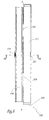
- the suspended file shown in Figure 1 includes two rigid rods 1, a sheet of cardboard 2 and a support 3 in which is mounted a label 4. Hooks 5, intended to be support on horizontal rails not shown, equip the ends of the rigid rods 1 which are connected to one another by the cardboard sheet 2. The latter forms the flanks 6 and the bottom, not shown, of the file suspended.
- a body 8 of the support 3 is fixed by gluing, riveting or by any other appropriate means on a sidewall 6, of which it partially overlaps one of the vertical edges since, in the example shown, the suspended file is more particularly intended to be installed in a wardrobe.
- a transparent and rigid shutter 9 of the support 3 is mounted to tilt on this body 8.
- Support 3 is generally symmetrical with respect to a plane P.
- its body 8 delimits holes 10 forming the female parts of two devices Continuous folders, button type pressure, whose male parts are on another suspended folder not shown and which allow to unite last in the folder shown in Figure 1.
- the distal edge of the body 8 has the shape of a display surface 11 against which is intended to be applied the label 4.
- the body 8 defines two protuberances 12, each of which is disposed at one end of the surface 11. Each protuberance 12 protrudes from the surface 11 and forms a stop for the identification tag 4.
- Two cylindrical housing and hollow 13 opposite, one of which only can be seen in Figure 2, are pierced in the protuberances 12 and centered on an axis X-X 'of tilting transparent component 9.
- Each end of the shutter 9 is provided with one of two hinges 14, which are complementary to the housing 13, directed in two opposite directions and centered on the axis tilting X-X 'once the body 8 and the shutter 9 assembled.
- the outer face 15 of the shutter 9 is essentially convex, so that this component 9 forms a magnifying glass for facilitate the reading of the inscriptions carried by the identification tag 4.
- Reference 16 designates the parts of the edge of the shutter 9 at the ends of this shutter 9.
- the body 8 and the flap 9 may, for example, be made of polyethylene. They can also be made of any other suitable material such as polystyrene or acrylonitrile butadiene copolymer styrene (ABS).
- ABS acrylonitrile butadiene copolymer styrene
- the assembly of the body 8 and the shutter 9 consists of introduce each hinge 14 into one of the housings 13, after what the support 3 is as illustrated in Figures 1 and 3.
- the hinges 14 and the housings 13 form a tilting mounting hinge of shutter 9 on the body 8.
- the body 8 and the shutter 9 retain and hold together an identification tag 4 installed in the support 3.
- the shutter 9 is maintained in position folded against the label 4 by friction of parts 16 of its edge on the protuberances 12, which block the label 4 in two opposite directions, parallel to the tilting axis X-X '.
- FIGS. 4 and 5 A support 103 according to a second embodiment of the invention is shown in FIGS. 4 and 5. In this following, we only describe what distinguishes it from the support represented in Figures 1 to 3. In addition, a reference used hereinafter to designate a part of the support 103 similar or equivalent to a referenced part of the medium 3 is obtained by increasing by 100 the reference identifying this part on the support 3.
- the transparent flap 109 of the support 103 is not rigid but elastically deformable, since it is constituted by an elastic band.
- the body 108 does not delimit holes 13 but a slot 113 which borders the surface 111 at a level big side of it.
- a longitudinal edge 117 of the shutter 109 is inserted and secured by gluing or any other means in the slot 113 which extends along an axis YY '. Because of its elastic properties, the strand 109 tends to fall back and apply itself against the surface 111.
- the shutter 109 can be made of any material suitable, for example styrene acrylonitrile copolymer (SAN).
- SAN styrene acrylonitrile copolymer
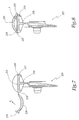
- a support 203 according to a third embodiment of the invention is shown in FIGS. following, we only describe what distinguishes it from the support 3.
- a reference used to designate hereafter part of the support 203 similar or equivalent to a referenced part of the support 3 is obtained by increasing 200 the reference identifying this part on the support 3.
- the transparent shutter 209 and the body 208 came from material and therefore form a single piece.
- This piece is molded by bi-injection of a plastic material transparent and an opaque plastic material and colored. This is done in such a way that shutter 209 is made of transparent plastic material and that the body 208 is made of colored plastic and opaque, whose chemical composition can be globally identical to that of the transparent plastic material.
- an X-axis hinge articulates the flap 209 to the body 208.
- this hinge does not have hinges 14 or housing 13, but it consists of material bridges 218, which connect the flap 209 to the body 208 and which, in the example represented, are two in number.
- Means for holding the shutter 209 in position retaining a label include a clip 219 and a complementary projection 220.
- the clip 219 is formed by a curved rib, which equips the shutter 209, at the level of its free and longitudinal edge.
- the projection 220 is defined by the body 208, in a recess 221 formed at the level one of the longitudinal edges of the display surface 211.
- the flap 209 is away from the display surface 211.
- this flap 209 is folded towards the display surface 211, that is to say in the direction indicated by the arrow F 1 in Figure 7, a longitudinal fold 222 is formed in each bridge 218.
- the clip 219 is deformed elastically. In FIG. 8, it is engaged on this projection 220 and thereby maintains the flap 209 in the retaining position of a label 4.
- a support 303 according to a fourth embodiment of the invention is shown in FIGS. 9 to 11 and comprises a body 308.
- This body 308 can advantageously delimit holes not shown, forming for example the female parts snap-button type devices, allowing the continuous of adjacent files. With this in mind, male parts of these devices are on a folder suspended adjacent to that provided with support 303.
- the body 308 defines a elongated beach 312, forming a display surface, that is to say receipt of the identification label.
- two longitudinal ends of this beach two cheeks 314, discoidal shape, came from matter with the body.
- These cheeks 314 have the same axis, denoted A, which is coincides with the longitudinal axis of range 312.
- the support 303 also includes a transparent component, designated in its together with reference 316.
- the latter has a main portion 318, generally semi-cylindrical and of circular section centered on the A axis. variant, this portion 318 may affect the shape of a cylinder portion extending at a different angle from 180 °.
- this main part 318 corresponds to that noted A cheeks 314, as well as the beach 312.
- This part main 318 has a length close to that of the range 312. It will also be noted that its external surface is convex, so that it forms a magnifying glass, which allows make it easier to read the inscriptions on the label 4.
- the main part 318 is extended axially by two jaws 320, forming the arc a circle whose center passes through the aforementioned axis A.
- These jaws 320 which are diametrically opposed, are respective recesses 322, allowing the receiving the outer periphery of the cheeks 314.
- the body 308 and the flap 316 may, for example, be made of polyethylene. They can also be made of any other suitable material, such as polystyrene or acrylonitrile butadiene copolymer styrene (ABS). Note that if component 316 is transparent, the body 308 is advantageously opaque.
- the assembly of this body and this component consists of force each jaw 320 into the periphery external of a corresponding cheek 314. Such a operation is made possible by the elasticity of the constituent material of shutter 316.
- the component 316 In use, in the position of Figures 10 and 11, the component 316 provides the user with access to 312. In these conditions, this one is able to to install, easily, the identification tag 4 on this reception area 312.
- the flap 316 is rotated about the axis A, so that one 316 1 of its lateral ends comes into contact with the surface facing the range 312. Moreover, it is advantageously provided locking means of the flap 316 relative to the body 308, in this position of covering the label 4, which is illustrated in Figure 9.
- the flap 316 is provided with a projection 324, adapted to penetrate by resiliently snapping into a corresponding recess 326, formed in walls of the body adjacent to the beach 312.
- the wall 316 1 advantageously wedges the identification tag 4, so as to avoid any deflection.
- the flanges 314 form abutments for the label 4, at the same time as they permit pivotal mounting of the flap 316, which is advantageous. It is furthermore conceivable that, if it is desired to remove a given label, it is a question of disengaging the projection 324 with respect to the recess 326, then of rotating the flap 316 so as to be able to access this label again.
- the file may not not be a hanging file for cabinet, without depart from the scope of the invention.
- it can be a hanging file for drawer.
- support label can be designed so that it can be mounted not at the level of a vertical edge of the sheet in cardboard 2 a hanging file for cabinet but at the level one of the horizontal and top edges of the sheet in cardboard 2 a hanging file for drawer.
- a label carrier according to the invention can combine features from many of the supports 3, 103, 203 and 303.
Landscapes
- Physics & Mathematics (AREA)
- General Physics & Mathematics (AREA)
- Engineering & Computer Science (AREA)
- Theoretical Computer Science (AREA)
- Sheet Holders (AREA)
Applications Claiming Priority (4)
| Application Number | Priority Date | Filing Date | Title |
|---|---|---|---|
| FR0401719A FR2866596B1 (fr) | 2004-02-20 | 2004-02-20 | Support d'etiquette d'identification pour dossier suspendu et dossier suspendu pourvu d'un tel support |
| FR0401719 | 2004-02-20 | ||
| FR0405580A FR2870480B1 (fr) | 2004-05-24 | 2004-05-24 | Support d'etiquette d'identification pour dossier suspendu et dossier suspendu d'un tel support |
| FR0405580 | 2004-05-24 |
Publications (2)
| Publication Number | Publication Date |
|---|---|
| EP1566285A2 true EP1566285A2 (de) | 2005-08-24 |
| EP1566285A3 EP1566285A3 (de) | 2006-01-04 |
Family
ID=34712675
Family Applications (1)
| Application Number | Title | Priority Date | Filing Date |
|---|---|---|---|
| EP05356036A Withdrawn EP1566285A3 (de) | 2004-02-20 | 2005-02-18 | Hängemappe mit Identifizierungsetikettenhalter |
Country Status (1)
| Country | Link |
|---|---|
| EP (1) | EP1566285A3 (de) |
Family Cites Families (5)
| Publication number | Priority date | Publication date | Assignee | Title |
|---|---|---|---|---|
| FR1528820A (fr) * | 1967-04-27 | 1968-06-14 | Val Rex | Perfectionnements apportés aux cavaliers porteurs d'étiquettes d'identification defiches ou analogues |
| FR2040760A5 (de) * | 1969-04-11 | 1971-01-22 | Organisation Economique | |
| SE402662B (sv) * | 1976-10-15 | 1978-07-10 | Lundvall Hl Plast | Hallare for remsformiga informationsberare |
| FR2593313B1 (fr) * | 1986-01-20 | 1989-07-28 | Nicollet Oblique | Gaine en matiere transparente equipant une chemise de classement de documents et destinee a recevoir une etiquette d'identification de ceux-ci |
| US5823353A (en) * | 1996-01-26 | 1998-10-20 | Perrin Manufacturing Company | Combination business card case and display case |
-
2005
- 2005-02-18 EP EP05356036A patent/EP1566285A3/de not_active Withdrawn
Also Published As
| Publication number | Publication date |
|---|---|
| EP1566285A3 (de) | 2006-01-04 |
Similar Documents
| Publication | Publication Date | Title |
|---|---|---|
| EP0847710B1 (de) | Federgelenk für Haarartikel | |
| EP0807844A1 (de) | Abnehmbares Federscharnier für Brille | |
| FR3022042A1 (fr) | Monture de lunettes a branches amovibles clipsees | |
| CA1279979C (fr) | Dispositif tel que sous-verre pour presenter un document | |
| EP0823065B1 (de) | Federscharnier fuer brillen | |
| FR2997769A1 (fr) | Charniere et branche de lunettes | |
| CA2004034C (fr) | Reliure pour album d'echantillons | |
| EP2663214B1 (de) | Objekthalter | |
| EP1566285A2 (de) | Hängemappe mit Identifizierungsetikettenhalter | |
| FR3065684A1 (fr) | Ensemble de garnissage comprenant une piece deployable | |
| EP1261477B1 (de) | Biegevorrichtung, insbesondere für eine flache blechplatte | |
| FR2795529A1 (fr) | Dispositif de fixation de branches sur face de lunettes, branche de lunettes et tenon associes | |
| WO1996015911A1 (fr) | Presentoir de documents | |
| FR2866596A1 (fr) | Support d'etiquette d'identification pour dossier suspendu et dossier suspendu pourvu d'un tel support | |
| FR2852794A1 (fr) | Boitier comportant un systeme de fermeture magnetique | |
| FR2747963A1 (fr) | Support d'etiquette d'identification et dossier suspendu comprenant un tel support | |
| FR3032380A1 (de) | ||
| FR2870480A1 (fr) | Support d'etiquette d'identification pour dossier suspendu et dossier suspendu d'un tel support | |
| FR2690486A1 (fr) | Pince à serrage instantané et à ouverture et à force de serrage réglables, et porte-copie équipé d'une telle pince. | |
| EP3801371B1 (de) | Vorrichtung zur aufbewahrung von orthodontischen zangen | |
| EP0834436A1 (de) | Papierhalter für einen rohrförmigen Schiebegriff eines Transportwagens und Schiebegriff ausgerüstet mit solchem Papierhalter | |
| FR2549124A1 (fr) | Charniere a systeme de rappel incorpore et organe quelconque equipe de cette charniere | |
| FR2601728A1 (fr) | Attache, notamment pour le montage d'un panneau | |
| FR3002876A1 (fr) | Agencement de couteau pliant | |
| FR2732875A1 (fr) | Dispositif de presentation pour au moins un echantillon de produit en tube |
Legal Events
| Date | Code | Title | Description |
|---|---|---|---|
| PUAI | Public reference made under article 153(3) epc to a published international application that has entered the european phase |
Free format text: ORIGINAL CODE: 0009012 |
|
| AK | Designated contracting states |
Kind code of ref document: A2 Designated state(s): AT BE BG CH CY CZ DE DK EE ES FI FR GB GR HU IE IS IT LI LT LU MC NL PL PT RO SE SI SK TR |
|
| AX | Request for extension of the european patent |
Extension state: AL BA HR LV MK YU |
|
| PUAL | Search report despatched |
Free format text: ORIGINAL CODE: 0009013 |
|
| AK | Designated contracting states |
Kind code of ref document: A3 Designated state(s): AT BE BG CH CY CZ DE DK EE ES FI FR GB GR HU IE IS IT LI LT LU MC NL PL PT RO SE SI SK TR |
|
| AX | Request for extension of the european patent |
Extension state: AL BA HR LV MK YU |
|
| AKX | Designation fees paid | ||
| REG | Reference to a national code |
Ref country code: DE Ref legal event code: 8566 |
|
| STAA | Information on the status of an ep patent application or granted ep patent |
Free format text: STATUS: THE APPLICATION IS DEEMED TO BE WITHDRAWN |
|
| 18D | Application deemed to be withdrawn |
Effective date: 20060704 |