EP1566210A1 - Method for removing harmful substance in bent gas - Google Patents
Method for removing harmful substance in bent gas Download PDFInfo
- Publication number
- EP1566210A1 EP1566210A1 EP03777165A EP03777165A EP1566210A1 EP 1566210 A1 EP1566210 A1 EP 1566210A1 EP 03777165 A EP03777165 A EP 03777165A EP 03777165 A EP03777165 A EP 03777165A EP 1566210 A1 EP1566210 A1 EP 1566210A1
- Authority
- EP
- European Patent Office
- Prior art keywords
- vent gas
- metal compound
- removing harmful
- harmful substances
- zeolite
- Prior art date
- Legal status (The legal status is an assumption and is not a legal conclusion. Google has not performed a legal analysis and makes no representation as to the accuracy of the status listed.)
- Granted
Links
Images
Classifications
-
- B—PERFORMING OPERATIONS; TRANSPORTING
- B01—PHYSICAL OR CHEMICAL PROCESSES OR APPARATUS IN GENERAL
- B01D—SEPARATION
- B01D53/00—Separation of gases or vapours; Recovering vapours of volatile solvents from gases; Chemical or biological purification of waste gases, e.g. engine exhaust gases, smoke, fumes, flue gases, aerosols
- B01D53/34—Chemical or biological purification of waste gases
- B01D53/46—Removing components of defined structure
- B01D53/68—Halogens or halogen compounds
- B01D53/70—Organic halogen compounds
-
- B—PERFORMING OPERATIONS; TRANSPORTING
- B01—PHYSICAL OR CHEMICAL PROCESSES OR APPARATUS IN GENERAL
- B01D—SEPARATION
- B01D53/00—Separation of gases or vapours; Recovering vapours of volatile solvents from gases; Chemical or biological purification of waste gases, e.g. engine exhaust gases, smoke, fumes, flue gases, aerosols
- B01D53/34—Chemical or biological purification of waste gases
- B01D53/46—Removing components of defined structure
- B01D53/68—Halogens or halogen compounds
- B01D53/685—Halogens or halogen compounds by treating the gases with solids
-
- B—PERFORMING OPERATIONS; TRANSPORTING
- B01—PHYSICAL OR CHEMICAL PROCESSES OR APPARATUS IN GENERAL
- B01D—SEPARATION
- B01D2251/00—Reactants
- B01D2251/30—Alkali metal compounds
-
- B—PERFORMING OPERATIONS; TRANSPORTING
- B01—PHYSICAL OR CHEMICAL PROCESSES OR APPARATUS IN GENERAL
- B01D—SEPARATION
- B01D2251/00—Reactants
- B01D2251/40—Alkaline earth metal or magnesium compounds
-
- B—PERFORMING OPERATIONS; TRANSPORTING
- B01—PHYSICAL OR CHEMICAL PROCESSES OR APPARATUS IN GENERAL
- B01D—SEPARATION
- B01D2253/00—Adsorbents used in seperation treatment of gases and vapours
- B01D2253/10—Inorganic adsorbents
- B01D2253/102—Carbon
-
- B—PERFORMING OPERATIONS; TRANSPORTING
- B01—PHYSICAL OR CHEMICAL PROCESSES OR APPARATUS IN GENERAL
- B01D—SEPARATION
- B01D2253/00—Adsorbents used in seperation treatment of gases and vapours
- B01D2253/10—Inorganic adsorbents
- B01D2253/106—Silica or silicates
- B01D2253/108—Zeolites
-
- B—PERFORMING OPERATIONS; TRANSPORTING
- B01—PHYSICAL OR CHEMICAL PROCESSES OR APPARATUS IN GENERAL
- B01D—SEPARATION
- B01D2257/00—Components to be removed
- B01D2257/20—Halogens or halogen compounds
- B01D2257/202—Single element halogens
- B01D2257/2027—Fluorine
-
- B—PERFORMING OPERATIONS; TRANSPORTING
- B01—PHYSICAL OR CHEMICAL PROCESSES OR APPARATUS IN GENERAL
- B01D—SEPARATION
- B01D2257/00—Components to be removed
- B01D2257/20—Halogens or halogen compounds
- B01D2257/206—Organic halogen compounds
- B01D2257/2066—Fluorine
-
- B—PERFORMING OPERATIONS; TRANSPORTING
- B01—PHYSICAL OR CHEMICAL PROCESSES OR APPARATUS IN GENERAL
- B01D—SEPARATION
- B01D2258/00—Sources of waste gases
- B01D2258/02—Other waste gases
- B01D2258/0216—Other waste gases from CVD treatment or semi-conductor manufacturing
Definitions
- the present invention relates to a method for removing harmful substances in a vent gas containing highly reactive halogen or halogen compound gas remaining in the pipeline of a cylinder cabinet that supplies gas to an etching unit, a CVD unit, etc. used in the manufacture of semiconductors and liquid crystals.
- Halogen or halogen compound gases are used for various purposes as an etchant gas, a cleaning gas, a raw material, etc. in etching and CVD processes in the manufacture of semiconductors and liquid crystals.
- a highly reactive halogen or halogen compound gas is fed from a cylinder cabinet to an etching or CVD unit.
- the reactive halogen or halogen compound gas remaining in the pipeline of the cabinet such as a gas feed pipe, is exhausted as vent gas before the replacement.
- the vent gas containing the halogen or halogen compound gas is not allowed to be released into the air so that a unit for removing harmful substances from vent gas must be installed.
- Wet methods and dry methods are known as methods using a treating agent for removing highly reactive halogen or halogen compound from exhaust gas.
- a wet method is a treatment of the exhaust gas with water or an aqueous solution of sodium hydroxide.
- Treatment (scrubbing) with water is mostly practiced because treatment with an aqueous solution of sodium hydroxide induces different problems such as wafer contamination.
- toxic oxidizing gas and acidic gas could be made non-toxic at high efficiency by using a large quantity of fresh water.
- treating (scrubbing) water is used in circulation for the time being in view of the amount of waste water. Therefore, toxic gas has been released without being thoroughly removed from vent gas.
- a dry method is a treatment of exhaust gas with a solid treating agent.
- Various treating agents have been proposed.
- Japanese Patent 2778031 proposes an adsorbent for nitrogen oxides and sulfur oxides which comprises calcium sulfate, calcium hydroxide, activated carbon, amorphous carbon, and an alkali metal compound.
- JP-A-2001-338910 discloses a method of treating halogen-containing gas which comprises the steps of bringing the gas into contact with a treating agent containing iron oxide, an alkaline earth metal compound, and activated carbon and bringing the thus treated gas into contact with a treating agent comprising zeolite.
- adsorbent and treating agent use a large quantity of activated carbon with a large specific surface area to enhance the effect of contact with a halogen compound gas. It is true that a large amount of a halogen compound gas is adsorbed on activated carbon. However, because of the high reducing power of activated carbon, an rapid reaction can occur between the halogen compound gas adsorbed onto the treating agent and activated carbon, which induce an explosion.
- An object of the present invention is to provide a method for removing harmful substances in the vent gas containing halogen or halogen compound gas remaining in the pipeline of a cylinder cabinet for feeding gas to an etching unit, a CVD unit, etc. used in the manufacture of semiconductors and liquid crystals thereby to render the gas harmless safely and efficiently.
- an activated carbon-containing treating agent having incorporated therein incombustible zeolite has a relatively large specific surface area notwithstanding a reduced content of activated carbon and is capable of removing highly reactive halogen or halogen compound gas, such as F 2 or COF 2 , from vent gas with safety and high efficiency.
- the present invention provides a method for removing harmful substances in the vent gas containing halogen or halogen compound gas remaining in the pipeline of a cylinder cabinet, characterized by bringing the vent gas into contact with a treating agent comprising an alkaline earth metal compound, an alkali metal compound, zeolite, and a carbonaceous material.
- the proportion of activated carbon in the treating agent can be reduced, which avoids explosion. And yet the treating agent has a relatively large specific surface area to enjoy a large effect of contact with vent gas.
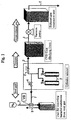
- Fig. 1 shows an embodiment of the system in which a cylinder cabinet supplies highly reactive halogen or halogen compound gas to a CVD (or etching) unit, and vent gas remaining in the pipeline of the cylinder cabinet is treated in a unit for removing harmful substances from vent gas.
- CVD chemical vapor deposition
- the cylinder cabinet is connected to the unit for removing harmful substances from vent gas via a pipe 1 and to the CVD (or etching) unit via a gas feed pipe 2.
- the CVD (or etching) unit is connected to a vacuum pump via a pipe 3 and then to an exhaust gas treatment unit.
- a valve 4 in the pipe 1 is closed during gas feed to the CVD (or etching) unit.
- valves of cylinders 5 and a valve 6 in the gas feed pipe 2 are closed, and the valve 4 in the pipe 1 is opened.
- Nitrogen gas is introduced through a pipe 7, and the halogen or halogen compound gas remaining in the pipeline of the cylinder cabinet is evacuated with the nitrogen gas and introduced into the unit for removing harmful substances from vent gas.
- the halogen or halogen compound gas introduced into the unit for removing harmful substances from vent gas is brought into contact with the treating agent to be made harmless and released into the air through a pipe 8.
- the treating agent packed in the unit for removing harmful substances from vent gas comprises an alkaline earth metal compound, an alkali metal compound, zeolite, and a carbonaceous material.
- the alkaline earth metal compound that can be used in the treating agent includes oxides, hydroxides, carbonates, and sulfates of calcium, magnesium, barium, and strontium. Calcium oxide and hydroxide are particularly preferred of them. These alkaline earth metal compounds can be used either individually or as a combination of two or more thereof.
- the alkaline earth metal compound preferably has a particle size of 500 ⁇ m or less, still preferably 200 to 300 ⁇ m, and a specific surface area of 1 to 10 m 2 /g, still preferably 2 to 3 m 2 /g.
- the alkali metal compound that can be used in the treating agent includes oxides, hydroxides, carbonates, and sulfates of sodium, potassium, and cesium. Preferred of them are sodium oxide and hydroxide and potassium oxide and hydroxide. These alkali metal compounds can be used either individually or as a combination of two or more thereof.
- the alkali metal compound preferably has a particle size of 500 ⁇ m or less, still preferably 200 to 300 ⁇ m, and a specific surface area of 1 to 10 m 2 /g, still preferably 2 to 3 m 2 /g.
- Soda lime can be used as the alkaline earth metal compound and the alkali metal compound.
- Soda lime to be used preferably has a particle size of 500 ⁇ m or less, still preferably 200 to 300 ⁇ m, and a specific surface area of 1 to 100 m 2 /g, still preferably 2 to 30 m 2 /g.
- Zeolite that can be used in the treating agent preferably has fine pores with a pore diameter of 3 ⁇ or more, still preferably 8 to 10 ⁇ .
- X type zeolite and faujasite type zeolite are preferred for their large void volume in nature of their structures.
- X type zeolite is still preferred. Having a relatively high silicon dioxide content, faujasite type zeolite is liable to react with hydrogen fluoride to destroy the structure of zeolite. It can follow that the capacity for treating hydrogen fluoride is reduced.
- the zeolite prefferably has a particle size of 500 ⁇ m or less, still preferably 100 to 300 ⁇ m, and a specific surface area of 100 to 500 m 2 /g, still preferably 200 to 400 m 2 /g.
- the carbonaceous material that can be used in the treating agent is preferably coke and/or activated carbon. Porous coke obtained by high-temperature dry distillation of coal is particularly preferred.
- the carbonaceous material prefferably has a particle size of 500 ⁇ m or less, still preferably 200 to 300 ⁇ m, and a specific surface area of 1000 to 1500 m 2 /g, still preferably 1100 to 1200 m 2 /g.
- the treating agent preferably comprises 60% or more by mass of the alkaline earth metal compound, 1 to 3% by mass of the alkali metal compound, 5 to 37% by mass of zeolite, and 5% by mass or less of the carbonaceous material. Still preferably, it comprises 70 to 87% by mass of the alkaline earth metal compound, 2 to 3% by mass of the alkali metal compound, 5 to 10% by mass of zeolite, and 0.5 to 5% by mass of the carbonaceous material. It is the most preferred that the treating agent comprise 80 to 87% by mass of the alkaline earth metal compound, 2 to 3% by mass of the alkali metal compound, 5 to 7% by mass of zeolite, and 2 to 5% by mass of the carbonaceous material.
- the treating agent may be a mixture as obtained by dry blending the alkaline earth metal compound, alkali metal compound, zeolite, and carbonaceous material each in powder form in the above-recited compounding ratio. It is preferred to formulate the mixture into granules by mixing the powders, preferably powders having a particle size of 500 ⁇ m or less, followed by kneading with water, etc., followed by granulation.
- the treating agent in the form of granules have a particle size of 1 to 5 mm, still preferably 2 to 4 mm, be porous, and have a specific surface area of 10 to 40 m 2 /g, still preferably 20 to 30 m 2 /g.
- Kneading of powders and granulation are carried out, for example, as follows.
- the components each in powder form are mixed and kneaded with water in, e.g., a Henschel mixer, followed by granulation. Mixing and kneading can be performed with commonly used equipment. A binder may be added in mixing and kneading.
- the vent gas that can be rendered harmless by the method of the present invention is one containing highly reactive halogen or halogen compound gas, e.g., F 2 or COF 2 , remaining in the pipeline of a cylinder cabinet that feeds gas to an etching unit, a CVD unit, and like equipment used in the manufacture of semiconductors or liquid crystals.
- highly reactive halogen or halogen compound gas e.g., F 2 or COF 2
- the exhaust gas from the CVD (or etching) unit is sent, through the pipe 3, to an exhaust gas treatment unit packed with a treating agent, where it is made harmless on contact with the treating agent and then vented into the open air.
- the treating agent to be packed into the exhaust gas treatment unit may be the above-described treatment agent used in the unit for removing harmful substances from vent gas.
- the method for removing harmful substances in the vent gas of the present invention is not limited to the embodiment shown in Fig. 1. That is, the method of the invention can be effected in the same manner as in conventional dry methods for treating vent gas, except for using the treating agent comprising the alkaline earth metal compound, alkali metal compound, zeolite, and carbonaceous material as an agent to be brought into contact with vent gas containing halogen or halogen compound gas remaining in the pipeline of a cylinder cabinet.
- treating conditions including amount of the treating agent to be packed, vent gas flow rate, halogen or halogen compound gas concentration and linear velocity of vent gas, vent gas retention time, and treating temperature and pressure, are decided appropriately depending on the kind of vent gas.
- the halogen or halogen compound gas concentration in vent gas is from the threshold limit value up to 10.0%, preferably 0.1 % to 1.0%;
- the linear velocity is 10 m/sec or lower, preferably 1 to 5 m/sec;
- the retention time of vent gas is 1 to 100 seconds, preferably 10 to 50 seconds;
- the treating temperature is normal temperature (20 to 30°C); and the treating pressure is atmospheric pressure.
- a hundred parts by weight of a compounded mixture shown in Table 1 below was kneaded with 100 parts by weight of water and granulated to prepare a granular treating agent having an average particle diameter of 2 mm, an average length of 4 mm, and a specific surface area of 30 m 2 /g.
- gas containing F 2 or COF 2 remaining in the pipeline of the cylinder cabinet was treated as vent gas with the resulting treating agent.
- the adsorption column was set vertically, and the treating agent was packed therein.
- the F 2 or COF 2 remaining in the pipeline of the cylinder cabinet was diluted with nitrogen to a concentration of 0.1 to 10.0% and treated under atmospheric pressure at normal temperature (20°C).
- the linear velocity was 10 m/sec or lower, and the gas retention time was between 1 second and 100 seconds.
- the gas was sampled at the gas inlet, the middle point, and the gas outlet of the column and analyzed by gas chromatography, FT-IR, a gas detection tube, ion chromatography, ICP, etc.
- the time when the F 2 or COF 2 concentration in the sample taken from the gas outlet reached the TLV (threshold limit value) was taken as a measure of breakthrough of the treating capacity.
- the ion chromatography and ICP analysis were conducted on a solution of the sample gas in an aqueous alkali solution.
- test results (treating capacity of the treating agents) are shown in Table 2 below.
- Vent gas containing F 2 or COF 2 was treated in the same method as in Example 1, except for using the compounded mixture shown in Table 1.
- the treating capacity of the treating agents is shown in Table 2. (unit: % by mass)
- the method for removing harmful substances in the vent gas of the present invention makes it possible to safely and efficiently render highly reactive halogen or halogen compound gas-containing vent gas harmless, the vent gas remaining in the pipeline of a cylinder cabinet for feeding gas to an etching unit, a CVD unit, etc. used in the manufacture of semiconductors and liquid crystals.
Landscapes
- Engineering & Computer Science (AREA)
- Chemical & Material Sciences (AREA)
- Health & Medical Sciences (AREA)
- Biomedical Technology (AREA)
- Environmental & Geological Engineering (AREA)
- Analytical Chemistry (AREA)
- General Chemical & Material Sciences (AREA)
- Oil, Petroleum & Natural Gas (AREA)
- Chemical Kinetics & Catalysis (AREA)
- Treating Waste Gases (AREA)
- Solid-Sorbent Or Filter-Aiding Compositions (AREA)
Abstract
Description
| (unit: % by mass) | ||||||||
| Example 1 | Comparative Example No. | |||||||
| 1 | 2 | 3 | 4 | 5 | 6 | 7 | ||
| Soda Lime (ordinary grade) | 90 | 100 | - | - | - | 70 | 90 | 95 |
| Soda Lime(high specific surface area grade) | - | - | - | - | 100 | - | - | - |
| Zeolite | 5 | - | - | 100 | - | - | - | - |
| Coke | 5 | - | - | - | - | - | - | - |
| Activated Carbon | - | - | - | - | - | 30 | 10 | 5 |
| Activated Alumina | - | - | 100 | - | - | - | - | - |
| Mass Ratio of Gas Trapped per Unit Mass of Treating Agent | ||||||||
| Example 1 | Comparative Example No. | |||||||
| 1 | 2 | 3 | 4 | 5 | 6 | 7 | ||
| F2 | 0.46 | 0.02 | 0.08 | 0.23 | 0.22 | 0.14 | 0.30 | 0.08 |
| COF2 | 0.66 | 0.03 | 0.11 | 0.3 | 0.28 | 0.17 | 0.37 | 0.11 |
Claims (12)
- A method for removing harmful substances in a vent gas containing a halogen or halogen compound gas remaining in the pipeline of a cylinder cabinet, characterized by bringing the vent gas into contact with a treating agent comprising an alkaline earth metal compound, an alkali metal compound, zeolite, and a carbonaceous material.
- The method for removing harmful substances in the vent gas according to claim 1, wherein the halogen or halogen compound gas is F2 or COF2.
- The method for removing harmful substances in the vent gas according to claim 1, wherein the alkaline earth metal compound is at least one member selected from the group consisting of an oxide, a hydroxide, a carbonate, and a sulfate of calcium, magnesium, barium, and strontium.
- The method for removing harmful substances in the vent gas according to claim 1, wherein the alkali metal compound is at least one member selected from the group consisting of an oxide, a hydroxide, a carbonate, and a sulfate of sodium, potassium, and cesium.
- The method for removing harmful substances in the vent gas according to claim 1, wherein the alkaline earth metal compound and the alkali metal compound are soda lime.
- The method for removing harmful substances in the vent gas according to claim 1, wherein the zeolite has fine pores with a pore diameter of 3 Å or more.
- The method for removing harmful substances in the vent gas according to claim 1, wherein the zeolite is X-type zeolite or faujasite type zeolite.
- The method for removing harmful substances in the vent gas according to claim 1, wherein the zeolite is X-type zeolite or faujasite type zeolite and has fine pores with a pore diameter of 3 Å or more.
- The method for removing harmful substances in the vent gas according to claim 1, wherein the carbonaceous material is coke and/or activated carbon.
- The method for removing harmful substances in the vent gas according to claim 1, wherein the treating agent comprises 60% or more by mass of the alkaline earth metal compound, 1 to 3% by mass of the alkali metal compound, 5 to 37% by mass of the zeolite, and 5% by mass or less of the carbonaceous material.
- The method for removing harmful substances in the vent gas according to claim 1, wherein each of the alkaline earth metal compound, the alkali metal compound, the zeolite, and the carbonaceous material is powder having a particle size of 500 µm or less.
- The method for removing harmful substances in the vent gas according to claim 1, wherein the treating agent is granules prepared by mixing the alkaline earth metal compound, the alkali metal compound, the zeolite, and the carbonaceous material each in powder form, kneading the mixture, and granulating the mixture.
Applications Claiming Priority (3)
| Application Number | Priority Date | Filing Date | Title |
|---|---|---|---|
| JP2002348736 | 2002-11-29 | ||
| JP2002348736A JP3871127B2 (en) | 2002-11-29 | 2002-11-29 | Vent gas removal method and treatment agent |
| PCT/JP2003/015217 WO2004050217A1 (en) | 2002-11-29 | 2003-11-28 | Method for removing harmful substance in bent gas |
Publications (3)
| Publication Number | Publication Date |
|---|---|
| EP1566210A1 true EP1566210A1 (en) | 2005-08-24 |
| EP1566210A4 EP1566210A4 (en) | 2006-06-21 |
| EP1566210B1 EP1566210B1 (en) | 2009-04-15 |
Family
ID=32462936
Family Applications (1)
| Application Number | Title | Priority Date | Filing Date |
|---|---|---|---|
| EP03777165A Expired - Lifetime EP1566210B1 (en) | 2002-11-29 | 2003-11-28 | Method for removing harmful substance in vent gas |
Country Status (5)
| Country | Link |
|---|---|
| US (1) | US7326279B2 (en) |
| EP (1) | EP1566210B1 (en) |
| JP (1) | JP3871127B2 (en) |
| DE (1) | DE60327242D1 (en) |
| WO (1) | WO2004050217A1 (en) |
Cited By (2)
| Publication number | Priority date | Publication date | Assignee | Title |
|---|---|---|---|---|
| WO2007042749A1 (en) * | 2005-10-07 | 2007-04-19 | Edwards Limited | Method of treating a gas stream |
| EP1967254A1 (en) * | 2007-02-21 | 2008-09-10 | Tosoh Corporation | Agent for rendering halogen-containing gas harmless, and method of rendering halogen-containing gas harmless using same |
Families Citing this family (3)
| Publication number | Priority date | Publication date | Assignee | Title |
|---|---|---|---|---|
| JP5145904B2 (en) * | 2007-02-21 | 2013-02-20 | 東ソー株式会社 | Halogen-based gas scavenger and halogen-based gas scavenging method using the same |
| CN103109175B (en) * | 2010-10-20 | 2015-07-08 | 株式会社爱发科 | Method of measuring viscoelasticity coefficients of material and device for measuring viscoelasticity coefficients of material |
| KR101192382B1 (en) | 2011-01-19 | 2012-10-17 | 주식회사 애니텍 | Low level CO2 absorbent manufacturing method |
Family Cites Families (14)
| Publication number | Priority date | Publication date | Assignee | Title |
|---|---|---|---|---|
| JP2778031B2 (en) | 1987-12-29 | 1998-07-23 | 松下電器産業株式会社 | Nitrogen oxide / sulfur oxide absorbent |
| JPH0716583B2 (en) * | 1990-08-10 | 1995-03-01 | セントラル硝子株式会社 | Method for dry treatment of exhaust gas containing chlorine fluoride |
| JP2941079B2 (en) | 1991-04-10 | 1999-08-25 | セントラル硝子株式会社 | Film forming apparatus with sediment recovery device |
| JPH08215539A (en) * | 1995-02-17 | 1996-08-27 | Central Glass Co Ltd | Treatment of halogen-containing gas |
| US5882615A (en) * | 1995-07-28 | 1999-03-16 | Japan Pionics Co., Ltd. | Cleaning agent and cleaning process for harmful gas |
| GB9621620D0 (en) * | 1996-10-17 | 1996-12-11 | Intersurgical Ltd | Process for the manufacture of chemical absorbents,and novel chemical absorbent formulations |
| JP3908819B2 (en) * | 1997-03-14 | 2007-04-25 | 大陽日酸株式会社 | CFC recovery method |
| US6060034A (en) * | 1998-06-02 | 2000-05-09 | L'air Liquide, Societe Anonyme Pour L'etude Et L'exploitation Des Procedes Georges Claude | Abatement system for ClF3 containing exhaust gases |
| JP4237942B2 (en) * | 1998-08-17 | 2009-03-11 | 株式会社荏原製作所 | Method and apparatus for treating exhaust gas containing fluorine-containing compound |
| JP2000140576A (en) * | 1998-11-05 | 2000-05-23 | Kanto Denka Kogyo Co Ltd | Detoxification system for fluorine-containing gas-containing mixture |
| KR100481584B1 (en) * | 2000-05-26 | 2005-04-08 | 쇼와 덴코 가부시키가이샤 | Harm-removing agent and method for rendering halogen-containing gas harmless and uses thereof |
| JP3840877B2 (en) | 2000-05-26 | 2006-11-01 | 昭和電工株式会社 | Halogen-based gas detoxifying agent, detoxifying method and use thereof |
| US6649082B2 (en) * | 2000-05-26 | 2003-11-18 | Showa Denko K.K. | Harm-removing agent and method for rendering halogen-containing gas harmless and uses thereof |
| US6805728B2 (en) * | 2002-12-09 | 2004-10-19 | Advanced Technology Materials, Inc. | Method and apparatus for the abatement of toxic gas components from a semiconductor manufacturing process effluent stream |
-
2002
- 2002-11-29 JP JP2002348736A patent/JP3871127B2/en not_active Expired - Lifetime
-
2003
- 2003-11-28 EP EP03777165A patent/EP1566210B1/en not_active Expired - Lifetime
- 2003-11-28 WO PCT/JP2003/015217 patent/WO2004050217A1/en not_active Ceased
- 2003-11-28 US US10/528,355 patent/US7326279B2/en not_active Expired - Lifetime
- 2003-11-28 DE DE60327242T patent/DE60327242D1/en not_active Expired - Lifetime
Cited By (4)
| Publication number | Priority date | Publication date | Assignee | Title |
|---|---|---|---|---|
| WO2007042749A1 (en) * | 2005-10-07 | 2007-04-19 | Edwards Limited | Method of treating a gas stream |
| US8834824B2 (en) | 2005-10-07 | 2014-09-16 | Edwards Limited | Method of treating a gas stream |
| EP1967254A1 (en) * | 2007-02-21 | 2008-09-10 | Tosoh Corporation | Agent for rendering halogen-containing gas harmless, and method of rendering halogen-containing gas harmless using same |
| US8282900B2 (en) | 2007-02-21 | 2012-10-09 | Tosoh Corporation | Agent for rendering halogen-containing gas harmless, and method of rendering halogen-containing gas harmless using same |
Also Published As
| Publication number | Publication date |
|---|---|
| JP3871127B2 (en) | 2007-01-24 |
| EP1566210A4 (en) | 2006-06-21 |
| US7326279B2 (en) | 2008-02-05 |
| EP1566210B1 (en) | 2009-04-15 |
| US20060032373A1 (en) | 2006-02-16 |
| WO2004050217A1 (en) | 2004-06-17 |
| DE60327242D1 (en) | 2009-05-28 |
| JP2004181299A (en) | 2004-07-02 |
Similar Documents
| Publication | Publication Date | Title |
|---|---|---|
| US6649082B2 (en) | Harm-removing agent and method for rendering halogen-containing gas harmless and uses thereof | |
| EP0277706B1 (en) | Toxic gas absorbent and process for making and using same | |
| JP2001338910A (en) | Abatement agent for halogen type gas, abatement method and its use | |
| JPS6161619A (en) | Treatment of waste gas | |
| EP1004345B1 (en) | Acid component-removing agent, method for producing it and method for removing acid components | |
| JP3789277B2 (en) | Reagent for decomposing fluorine compounds, decomposing method and use thereof | |
| KR20180114012A (en) | Composition for flue gas cleaning | |
| US6146606A (en) | Reactive agent and process for decomposing nitrogen fluoride | |
| US7326279B2 (en) | Method for removing harmful substance in vent gas | |
| JP2581642B2 (en) | Etching exhaust gas abatement agent and exhaust gas treatment method | |
| KR100481584B1 (en) | Harm-removing agent and method for rendering halogen-containing gas harmless and uses thereof | |
| TWI809256B (en) | Regeneration method of carbonic acid-type layered double hydroxide and acid exhaust gas treatment equipment | |
| JP2001017831A (en) | Treating agent for halogen gas | |
| KR20180111823A (en) | Composition for flue gas cleaning | |
| JPH0494723A (en) | Dry process for treatment of waste gas containing chlorine fluoride | |
| KR100529748B1 (en) | Method for Purifying Sulfur Hexafluoride | |
| JPH0251654B2 (en) | ||
| JP2004181300A (en) | Treatment agent for oxidizing gas and acid gas and detoxification method using the treatment agent | |
| EP4446733A1 (en) | Method for analyzing gas containing nitrosyl fluoride, and method for removing nitrosyl fluoride in gas | |
| JP2000140576A (en) | Detoxification system for fluorine-containing gas-containing mixture | |
| JP5147146B2 (en) | Waste incineration fly ash treatment method | |
| JP2005040766A (en) | Treatment agent and treatment method for exhaust gas containing acid gas and / or hydrocarbon | |
| JP4276333B2 (en) | Exhaust gas purification method | |
| JP3867306B2 (en) | Dust disposal method | |
| JPH07155541A (en) | Method for removing nitrogen trifluoride gas |
Legal Events
| Date | Code | Title | Description |
|---|---|---|---|
| PUAI | Public reference made under article 153(3) epc to a published international application that has entered the european phase |
Free format text: ORIGINAL CODE: 0009012 |
|
| 17P | Request for examination filed |
Effective date: 20050318 |
|
| AK | Designated contracting states |
Kind code of ref document: A1 Designated state(s): AT BE BG CH CY CZ DE DK EE ES FI FR GB GR HU IE IT LI LU MC NL PT RO SE SI SK TR |
|
| RBV | Designated contracting states (corrected) |
Designated state(s): DE FR GB IT NL |
|
| A4 | Supplementary search report drawn up and despatched |
Effective date: 20060524 |
|
| 17Q | First examination report despatched |
Effective date: 20061214 |
|
| RTI1 | Title (correction) |
Free format text: METHOD FOR REMOVING HARMFUL SUBSTANCE IN VENT GAS |
|
| GRAP | Despatch of communication of intention to grant a patent |
Free format text: ORIGINAL CODE: EPIDOSNIGR1 |
|
| GRAS | Grant fee paid |
Free format text: ORIGINAL CODE: EPIDOSNIGR3 |
|
| GRAA | (expected) grant |
Free format text: ORIGINAL CODE: 0009210 |
|
| RAP1 | Party data changed (applicant data changed or rights of an application transferred) |
Owner name: RESEARCH INSTITUTE OF INNOVATIVE TECHNOLOGY FOR TH Owner name: NATIONAL INSTITUTE OF ADVANCED INDUSTRIAL SCIENCE Owner name: KANTO DENKA KOGYO CO., LTD. |
|
| AK | Designated contracting states |
Kind code of ref document: B1 Designated state(s): DE FR GB IT NL |
|
| REG | Reference to a national code |
Ref country code: GB Ref legal event code: FG4D |
|
| RAP2 | Party data changed (patent owner data changed or rights of a patent transferred) |
Owner name: SHOWA DENKO K.K. Owner name: KANTO DENKA KOGYO CO., LTD. Owner name: DAIKIN INDUSTRIES, LTD. Owner name: TOKYO ELECTRON LIMITED Owner name: HITACHI KOKUSAI ELECTRIC INC. Owner name: NATIONAL INSTITUTE OF ADVANCED INDUSTRIAL SCIENCE |
|
| REF | Corresponds to: |
Ref document number: 60327242 Country of ref document: DE Date of ref document: 20090528 Kind code of ref document: P |
|
| NLT2 | Nl: modifications (of names), taken from the european patent patent bulletin |
Owner name: KANTO DENKA KOGYO CO., LTD. EN NATIONAL INSTITUTE Effective date: 20090527 |
|
| PLBE | No opposition filed within time limit |
Free format text: ORIGINAL CODE: 0009261 |
|
| STAA | Information on the status of an ep patent application or granted ep patent |
Free format text: STATUS: NO OPPOSITION FILED WITHIN TIME LIMIT |
|
| 26N | No opposition filed |
Effective date: 20100118 |
|
| REG | Reference to a national code |
Ref country code: DE Ref legal event code: R082 Ref document number: 60327242 Country of ref document: DE Representative=s name: BOETERS & LIECK, DE |
|
| REG | Reference to a national code |
Ref country code: DE Ref legal event code: R081 Ref document number: 60327242 Country of ref document: DE Owner name: NATIONAL INSTITUTE OF ADVANCED INDUSTRIAL SCIE, JP Free format text: FORMER OWNER: DAIKIN INDUSTRIES, LTD., HITACHI KOKUSAI ELECTRIC INC., KANTO DENKA KOGYO CO., LTD., NATIONAL INSTITUTE OF ADVANCED , SHOWA DENK, , JP Effective date: 20130313 Ref country code: DE Ref legal event code: R081 Ref document number: 60327242 Country of ref document: DE Owner name: HITACHI KOKUSAI ELECTRIC INC., JP Free format text: FORMER OWNER: DAIKIN INDUSTRIES, LTD., HITACHI KOKUSAI ELECTRIC INC., KANTO DENKA KOGYO CO., LTD., NATIONAL INSTITUTE OF ADVANCED , SHOWA DENK, , JP Effective date: 20130313 Ref country code: DE Ref legal event code: R081 Ref document number: 60327242 Country of ref document: DE Owner name: KANTO DENKA KOGYO CO., LTD., JP Free format text: FORMER OWNER: DAIKIN INDUSTRIES, LTD., HITACHI KOKUSAI ELECTRIC INC., KANTO DENKA KOGYO CO., LTD., NATIONAL INSTITUTE OF ADVANCED , SHOWA DENK, , JP Effective date: 20130313 Ref country code: DE Ref legal event code: R081 Ref document number: 60327242 Country of ref document: DE Owner name: DAIKIN INDUSTRIES, LTD., JP Free format text: FORMER OWNER: DAIKIN INDUSTRIES, LTD., HITACHI KOKUSAI ELECTRIC INC., KANTO DENKA KOGYO CO., LTD., NATIONAL INSTITUTE OF ADVANCED , SHOWA DENK, , JP Effective date: 20130313 Ref country code: DE Ref legal event code: R081 Ref document number: 60327242 Country of ref document: DE Owner name: SHOWA DENKO K.K., JP Free format text: FORMER OWNER: DAIKIN INDUSTRIES, LTD., HITACHI KOKUSAI ELECTRIC INC., KANTO DENKA KOGYO CO., LTD., NATIONAL INSTITUTE OF ADVANCED , SHOWA DENK, , JP Effective date: 20130313 Ref country code: DE Ref legal event code: R082 Ref document number: 60327242 Country of ref document: DE Representative=s name: BOETERS & LIECK, DE Effective date: 20130313 Ref country code: DE Ref legal event code: R081 Ref document number: 60327242 Country of ref document: DE Owner name: KANTO DENKA KOGYO CO., LTD., JP Free format text: FORMER OWNERS: DAIKIN INDUSTRIES, LTD., OSAKA-SHI, JP; HITACHI KOKUSAI ELECTRIC INC., TOKIO/TOKYO, JP; KANTO DENKA KOGYO CO., LTD., TOKIO/TOKYO, JP; NATIONAL INSTITUTE OF ADVANCED INDUSTRIAL SCIENCE AND TECHNOLOGY, TOKYO, JP; SHOWA DENKO K.K., TOKYO, JP; TOKYO ELECTRON LTD., TOKYO, JP Effective date: 20130313 Ref country code: DE Ref legal event code: R081 Ref document number: 60327242 Country of ref document: DE Owner name: NATIONAL INSTITUTE OF ADVANCED INDUSTRIAL SCIE, JP Free format text: FORMER OWNERS: DAIKIN INDUSTRIES, LTD., OSAKA-SHI, JP; HITACHI KOKUSAI ELECTRIC INC., TOKIO/TOKYO, JP; KANTO DENKA KOGYO CO., LTD., TOKIO/TOKYO, JP; NATIONAL INSTITUTE OF ADVANCED INDUSTRIAL SCIENCE AND TECHNOLOGY, TOKYO, JP; SHOWA DENKO K.K., TOKYO, JP; TOKYO ELECTRON LTD., TOKYO, JP Effective date: 20130313 Ref country code: DE Ref legal event code: R081 Ref document number: 60327242 Country of ref document: DE Owner name: SHOWA DENKO K.K., JP Free format text: FORMER OWNERS: DAIKIN INDUSTRIES, LTD., OSAKA-SHI, JP; HITACHI KOKUSAI ELECTRIC INC., TOKIO/TOKYO, JP; KANTO DENKA KOGYO CO., LTD., TOKIO/TOKYO, JP; NATIONAL INSTITUTE OF ADVANCED INDUSTRIAL SCIENCE AND TECHNOLOGY, TOKYO, JP; SHOWA DENKO K.K., TOKYO, JP; TOKYO ELECTRON LTD., TOKYO, JP Effective date: 20130313 Ref country code: DE Ref legal event code: R081 Ref document number: 60327242 Country of ref document: DE Owner name: HITACHI KOKUSAI ELECTRIC INC., JP Free format text: FORMER OWNERS: DAIKIN INDUSTRIES, LTD., OSAKA-SHI, JP; HITACHI KOKUSAI ELECTRIC INC., TOKIO/TOKYO, JP; KANTO DENKA KOGYO CO., LTD., TOKIO/TOKYO, JP; NATIONAL INSTITUTE OF ADVANCED INDUSTRIAL SCIENCE AND TECHNOLOGY, TOKYO, JP; SHOWA DENKO K.K., TOKYO, JP; TOKYO ELECTRON LTD., TOKYO, JP Effective date: 20130313 Ref country code: DE Ref legal event code: R081 Ref document number: 60327242 Country of ref document: DE Owner name: DAIKIN INDUSTRIES, LTD., JP Free format text: FORMER OWNERS: DAIKIN INDUSTRIES, LTD., OSAKA-SHI, JP; HITACHI KOKUSAI ELECTRIC INC., TOKIO/TOKYO, JP; KANTO DENKA KOGYO CO., LTD., TOKIO/TOKYO, JP; NATIONAL INSTITUTE OF ADVANCED INDUSTRIAL SCIENCE AND TECHNOLOGY, TOKYO, JP; SHOWA DENKO K.K., TOKYO, JP; TOKYO ELECTRON LTD., TOKYO, JP Effective date: 20130313 |
|
| REG | Reference to a national code |
Ref country code: NL Ref legal event code: SD Effective date: 20130508 |
|
| REG | Reference to a national code |
Ref country code: FR Ref legal event code: TQ Owner name: NATIONAL INSTITUTE OF ADVANCED INDUSTRIAL SCIE, JP Effective date: 20130418 Ref country code: FR Ref legal event code: TQ Owner name: KANTO DENKA KOGYO CO., LTD. Effective date: 20130418 Ref country code: FR Ref legal event code: TQ Owner name: SHOWA DENKO K.K., JP Effective date: 20130418 Ref country code: FR Ref legal event code: TQ Owner name: HITACHI KOKUSAI ELECTRIC INC., JP Effective date: 20130418 Ref country code: FR Ref legal event code: TQ Owner name: DAIKIN INDUSTRIES, LTD., JP Effective date: 20130418 |
|
| REG | Reference to a national code |
Ref country code: GB Ref legal event code: 732E Free format text: REGISTERED BETWEEN 20130516 AND 20130522 |
|
| REG | Reference to a national code |
Ref country code: FR Ref legal event code: CA Effective date: 20130618 |
|
| REG | Reference to a national code |
Ref country code: FR Ref legal event code: PLFP Year of fee payment: 13 |
|
| REG | Reference to a national code |
Ref country code: FR Ref legal event code: PLFP Year of fee payment: 14 |
|
| REG | Reference to a national code |
Ref country code: FR Ref legal event code: PLFP Year of fee payment: 15 |
|
| REG | Reference to a national code |
Ref country code: DE Ref legal event code: R082 Ref document number: 60327242 Country of ref document: DE Representative=s name: BOETERS & LIECK, DE Ref country code: DE Ref legal event code: R081 Ref document number: 60327242 Country of ref document: DE Owner name: DAIKIN INDUSTRIES, LTD., JP Free format text: FORMER OWNERS: DAIKIN INDUSTRIES, LTD., OSAKA-SHI, JP; HITACHI KOKUSAI ELECTRIC INC., TOKIO/TOKYO, JP; KANTO DENKA KOGYO CO., LTD., TOKIO/TOKYO, JP; NATIONAL INSTITUTE OF ADVANCED INDUSTRIAL SCIENCE AND TECHNOLOGY, TOKYO, JP; SHOWA DENKO K.K., TOKYO, JP Ref country code: DE Ref legal event code: R081 Ref document number: 60327242 Country of ref document: DE Owner name: KANTO DENKA KOGYO CO., LTD., JP Free format text: FORMER OWNERS: DAIKIN INDUSTRIES, LTD., OSAKA-SHI, JP; HITACHI KOKUSAI ELECTRIC INC., TOKIO/TOKYO, JP; KANTO DENKA KOGYO CO., LTD., TOKIO/TOKYO, JP; NATIONAL INSTITUTE OF ADVANCED INDUSTRIAL SCIENCE AND TECHNOLOGY, TOKYO, JP; SHOWA DENKO K.K., TOKYO, JP Ref country code: DE Ref legal event code: R081 Ref document number: 60327242 Country of ref document: DE Owner name: SHOWA DENKO K.K., JP Free format text: FORMER OWNERS: DAIKIN INDUSTRIES, LTD., OSAKA-SHI, JP; HITACHI KOKUSAI ELECTRIC INC., TOKIO/TOKYO, JP; KANTO DENKA KOGYO CO., LTD., TOKIO/TOKYO, JP; NATIONAL INSTITUTE OF ADVANCED INDUSTRIAL SCIENCE AND TECHNOLOGY, TOKYO, JP; SHOWA DENKO K.K., TOKYO, JP Ref country code: DE Ref legal event code: R081 Ref document number: 60327242 Country of ref document: DE Owner name: NATIONAL INSTITUTE OF ADVANCED INDUSTRIAL SCIE, JP Free format text: FORMER OWNERS: DAIKIN INDUSTRIES, LTD., OSAKA-SHI, JP; HITACHI KOKUSAI ELECTRIC INC., TOKIO/TOKYO, JP; KANTO DENKA KOGYO CO., LTD., TOKIO/TOKYO, JP; NATIONAL INSTITUTE OF ADVANCED INDUSTRIAL SCIENCE AND TECHNOLOGY, TOKYO, JP; SHOWA DENKO K.K., TOKYO, JP |
|
| REG | Reference to a national code |
Ref country code: GB Ref legal event code: 732E Free format text: REGISTERED BETWEEN 20190509 AND 20190515 |
|
| REG | Reference to a national code |
Ref country code: NL Ref legal event code: PD Owner name: KANTO DENKA KOGYO CO., LTD.; JP Free format text: DETAILS ASSIGNMENT: CHANGE OF OWNER(S), ASSIGNMENT; FORMER OWNER NAME: SHOWA DENKO K.K. Effective date: 20190418 |
|
| PGFP | Annual fee paid to national office [announced via postgrant information from national office to epo] |
Ref country code: NL Payment date: 20221118 Year of fee payment: 20 Ref country code: IT Payment date: 20221130 Year of fee payment: 20 Ref country code: GB Payment date: 20221123 Year of fee payment: 20 Ref country code: FR Payment date: 20221118 Year of fee payment: 20 Ref country code: DE Payment date: 20220908 Year of fee payment: 20 |
|
| REG | Reference to a national code |
Ref country code: DE Ref legal event code: R071 Ref document number: 60327242 Country of ref document: DE |
|
| REG | Reference to a national code |
Ref country code: NL Ref legal event code: MK Effective date: 20231127 |
|
| REG | Reference to a national code |
Ref country code: GB Ref legal event code: PE20 Expiry date: 20231127 |
|
| PG25 | Lapsed in a contracting state [announced via postgrant information from national office to epo] |
Ref country code: GB Free format text: LAPSE BECAUSE OF EXPIRATION OF PROTECTION Effective date: 20231127 |
|
| PG25 | Lapsed in a contracting state [announced via postgrant information from national office to epo] |
Ref country code: GB Free format text: LAPSE BECAUSE OF EXPIRATION OF PROTECTION Effective date: 20231127 |