EP1566188A1 - Body fluid suction and collection unit - Google Patents
Body fluid suction and collection unit Download PDFInfo
- Publication number
- EP1566188A1 EP1566188A1 EP03811930A EP03811930A EP1566188A1 EP 1566188 A1 EP1566188 A1 EP 1566188A1 EP 03811930 A EP03811930 A EP 03811930A EP 03811930 A EP03811930 A EP 03811930A EP 1566188 A1 EP1566188 A1 EP 1566188A1
- Authority
- EP
- European Patent Office
- Prior art keywords
- plate
- body fluid
- fluid suction
- suction reservoir
- hook
- Prior art date
- Legal status (The legal status is an assumption and is not a legal conclusion. Google has not performed a legal analysis and makes no representation as to the accuracy of the status listed.)
- Withdrawn
Links
- 210000001124 body fluid Anatomy 0.000 title claims abstract description 69
- 239000010839 body fluid Substances 0.000 title claims abstract description 69
- 239000012530 fluid Substances 0.000 claims description 32
- 239000000725 suspension Substances 0.000 claims description 11
- 239000000463 material Substances 0.000 description 21
- 229920006351 engineering plastic Polymers 0.000 description 5
- -1 polypropylene Polymers 0.000 description 5
- 229920002430 Fibre-reinforced plastic Polymers 0.000 description 3
- 229930182556 Polyacetal Natural products 0.000 description 3
- 239000004743 Polypropylene Substances 0.000 description 3
- 239000011151 fibre-reinforced plastic Substances 0.000 description 3
- 229920006324 polyoxymethylene Polymers 0.000 description 3
- 229920001155 polypropylene Polymers 0.000 description 3
- 229910001220 stainless steel Inorganic materials 0.000 description 3
- 239000010935 stainless steel Substances 0.000 description 3
- 239000004698 Polyethylene Substances 0.000 description 2
- 229910052782 aluminium Inorganic materials 0.000 description 2
- XAGFODPZIPBFFR-UHFFFAOYSA-N aluminium Chemical compound [Al] XAGFODPZIPBFFR-UHFFFAOYSA-N 0.000 description 2
- 239000000945 filler Substances 0.000 description 2
- 229910052751 metal Inorganic materials 0.000 description 2
- 239000002184 metal Substances 0.000 description 2
- 238000000034 method Methods 0.000 description 2
- 229920003023 plastic Polymers 0.000 description 2
- 239000004033 plastic Substances 0.000 description 2
- 229920000573 polyethylene Polymers 0.000 description 2
- 239000002990 reinforced plastic Substances 0.000 description 2
- 229920001871 amorphous plastic Polymers 0.000 description 1
- 229920001887 crystalline plastic Polymers 0.000 description 1
- JEIPFZHSYJVQDO-UHFFFAOYSA-N iron(III) oxide Inorganic materials O=[Fe]O[Fe]=O JEIPFZHSYJVQDO-UHFFFAOYSA-N 0.000 description 1
- 238000004519 manufacturing process Methods 0.000 description 1
- 230000009022 nonlinear effect Effects 0.000 description 1
- 230000000704 physical effect Effects 0.000 description 1
- 238000011084 recovery Methods 0.000 description 1
- 239000002699 waste material Substances 0.000 description 1
- 238000004804 winding Methods 0.000 description 1
Images









Classifications
-
- A—HUMAN NECESSITIES
- A61—MEDICAL OR VETERINARY SCIENCE; HYGIENE
- A61M—DEVICES FOR INTRODUCING MEDIA INTO, OR ONTO, THE BODY; DEVICES FOR TRANSDUCING BODY MEDIA OR FOR TAKING MEDIA FROM THE BODY; DEVICES FOR PRODUCING OR ENDING SLEEP OR STUPOR
- A61M1/00—Suction or pumping devices for medical purposes; Devices for carrying-off, for treatment of, or for carrying-over, body-liquids; Drainage systems
-
- A—HUMAN NECESSITIES
- A61—MEDICAL OR VETERINARY SCIENCE; HYGIENE
- A61M—DEVICES FOR INTRODUCING MEDIA INTO, OR ONTO, THE BODY; DEVICES FOR TRANSDUCING BODY MEDIA OR FOR TAKING MEDIA FROM THE BODY; DEVICES FOR PRODUCING OR ENDING SLEEP OR STUPOR
- A61M1/00—Suction or pumping devices for medical purposes; Devices for carrying-off, for treatment of, or for carrying-over, body-liquids; Drainage systems
- A61M1/64—Containers with integrated suction means
- A61M1/68—Containers incorporating a flexible member creating suction
Definitions
- the present invention relates to a portable body fluid suction reservoir used to suck and evacuate body fluid from a wound cavity of a human body to improve the adhesiveness of tissue in the wound cavity, and thereby accelerate recovery.
- a body fluid suction reservoir in order to suck in and evacuate body fluid from a wound cavity of a human body.
- one end of a tube is inserted into the wound cavity to evacuate and lead the body fluid, and the other end of the tube is connected to a suction reservoir, whereby the body fluid in the wound cavity is collected and stored in the suction reservoir by negative pressure generated in the suction reservoir.
- JP-A-57-81346 As a mechanism for generating the negative pressure in the suction reservoir, there have been known a mechanism disclosed in JP-A-57-81346 in which a container with an extensible elastic member built-in (such as a spring, or rubber) is previously compressed, in other words, the elastic member is contracted to previously reduce the internal volumetric capacity, so that negative pressure is generated in the container due to restoring force of the elastic member to suck in and collect body fluid, and a mechanism disclosed in JP-A-50-84090 and 61-131751 for example, in which an expandable and extensible elastic member (a balloon or a diaphragm, for example) is provided in a rigid container, and is previously expanded by exhausting gas from the rigid container using internal air supply, exhaust, or other dynamic means, so that negative pressure is generated in the container due to contractive force of the elastic member to suck in and collect body fluid.
- an expandable and extensible elastic member a balloon or a diaphragm, for example
- the former mechanism Since the former mechanism starts to suck in a state where the container is squashed, it is very compact especially at the beginning of the suction in comparison with the latter mechanism, and has an advantage that it is superior in portability because it does not take much space when it is set to a patient. Further, the former mechanism is provided with a lock means for keeping the container in the squashed state and thus, can contribute to reducing the transferring and storing costs thereof.
- the suction apparatus disclosed in JP-A-57-81346 is made to release the lock means by folding a hinge portion of a plate, there is a possibility that the lock may be easily released due to external force even in a state where the suction apparatus is packaged or baled in transit or storage.
- hooks provide on two plates are configured to engaged with each other, which is advantageous in terms of manufacturing cost and space saving, there is a problem that the hooks cannot be locked due to creep deformation after repeated use.
- the present invention is made to solve the above problem of a conventional body fluid suction reservoir, and its object is to provide a body fluid suction reservoir which has advantages that it is not bulky even if set to a patient and is superior in portability, and in which a lock is not easily released by external force in a state where it is packaged or baled in transit or storage.
- a body fluid suction reservoir including a flexible bag, two plates for supporting the bag, a spring put between the two plates, and a lock consisting of a hook, a release part and a member different from the two plates, by which lock the spring is held in a compressed state between the two plates, which held state can be released.
- the above described lock may have flexibility.
- the lock can be held by one of the plates so as to be deformable from a first state in which the hook is engaged with the other plate to a second state in which the hook is not engaged, and the lock is urged to be in the first state.
- the above described hook may be adapted to move in parallel with a surface of the one plate when the lock is deformed from the first state to the second state.
- a part of each of the above described plates may protrude in at least two locations around the release part of the lock in a direction opposite to a direction toward which the release part is pressed.
- An engagement surface of the hook of the above described lock may have a portion protruding toward an engagement surface of the other plate on a tip side thereof, and the engagement face of the other plate may also have a portion protruding toward the engagement surface of the hook on a hole side.
- two or more of the above described springs may be arranged in a straight line in a longitudinal direction of the body fluid suction reservoir.
- the above described bag may include a fluid evacuate port, a lid for the fluid evacuate port, and a suspension hole, and the lid for the fluid evacuate port may be provided with a holding part so as to be held by the suspension hole.
- a body fluid suction reservoir including a flexible bag element having a fluid collecting port for taking in body fluid, a first plate and a second plate arranged in the bag element to face each other, an elastic member disposed between the first and second plates, and a lock body attached to the second plate, in which the lock body has a hook part and an operation part for displacing the lock portion (that is, a release part) so that the hook part is engaged with an engagement surface of the first plate to fix the first and second plates, thereby the elastic member is compressed and held between the first and second plates, and the operation part is operated to displace the hook part in parallel with a surface of the second plate, so that fixing of the first and second plates is released to generate negative pressure in the bag element.
- the above described lock body may be elastically deformable. Moreover, a part of the lock body can be fixed to the second plate and thus, the operation part may be operated so as to displace at least the hook part in parallel with the surface of the second plate, and the hook part may be adapted to return to an initial position after the operation.
- At least one of the first and second plates may have a cutout portion. Accordingly, the operation part may be disposed in the cutout portion or in correspondence with the cutout portion so as to be located inside an outline of the fluid suction reservoir.
- the first plate may include a first shell part forming a part of the outline of the body fluid suction reservoir and a core part provided on a side of the shell part, which faces the second plate.
- the second plate may include a second shell part forming a part of the outline of the body fluid suction reservoir.
- at least a part of the lock body is located on a side of the second shell facing the core part and thereby, the elastic member can be compressed and held by the core part and at least the part of the lock body.
- the first plate may include a first shell part forming a part of an outline of the body fluid suction reservoir and a first core part provided on a side of this shell part facing the second plate
- the second plate may include a second shell part forming a part of the outline of the body fluid suction reservoir and a second core part provided on a side of the shell part facing the first plate.
- the lock body may be attached to the second shell part or second core part, and the hook part is engaged with a surface of the first core part on an opposite side to the second plate (namely, with a hook engagement surface) to lock the first and second plates. Both ends of the elastic member are intervened between the first and second core parts and thereby the elastic member is held in a compressed state. According to this configuration, it is possible to make the first and second core parts harder than the first and second shell parts and therefore, constitute each part can be made from an appropriate material for each function, which makes possible to broaden the width of material selection.
- the above described lock body may have at least two hook parts, and the elastic member may be a spring.
- the body fluid suction reservoir of the invention may have at least two springs arranged in a straight line between the first and second plates as an elastic member.
- the bag element may have a fluid evacuate port, a lid for the fluid evacuate port, and a suspension hole, and the lid for the fluid evacuate port may be provided with a holding part for being held by the suspension hole.
- the bag element may have a holding part attachment hole for holding the holding part, separately from the suspension hole.
- a fluid collecting port 5 is attached to pass through a bag 1, such that a drainage tube (not shown) kept in a patient is connected to the port 5.
- the fluid collecting port 5 has a fluid collecting port one way valve 6 so that body fluid collected in the bag 1 does not flow back into a body cavity of the patient.
- a fluid evacuate port 7 is provided to pass through the bag 1, and is provided with a lid 8 for the fluid evacuate port to be attached to the fluid evacuate port 7 during suction and collection (Fig. 3). Accordingly, when the suction and the collection are completed, the body fluid is evacuated by removing the fluid evacuate port lid 8 from the fluid evacuate port 7.
- a spring 3 in a state before the suction and the collection of the body fluid, a spring 3, two plates (a first plate 11 and a second plate 12) holding the spring 3 therebetween, and a lock body 4 for locking the two plates in a state in which the spring 3 is compressed are arranged in the bag 1.
- a transparent portion of the lock body 4 is made clear by drawing diagonal broken lines.
- two or more of the springs 3 are arranged in a straight line in a longitudinal direction of the body fluid suction reservoir. This provides a slim shape, compared to a case of using one spring 3, in order to generate the same suction capacity and the suction pressure and accordingly, it is possible to make the body fluid suction reservoir easily enter a pocket when carrying it.
- the spring 3 has a frustum shape, and can be folded up to a thickness one to three times larger than the diameter of a spring material without interference of a wire material of the spring, which realizes space saving in storage. Moreover, by forming the spring 3 into a shape of which winding pitch is gradually widened from a minor diameter side of the frustum to a major diameter side thereof, the non-linear property of the relation between load and deflection is restrained, which is more preferable for preventing suction pressure from being suddenly reduced at the beginning of the suction. Moreover, as a material of the spring 3, stainless steel which is not readily rust away is preferable. However, since it is not a portion directly contacting with a human body, the material is not restricted as long as the material has elasticity capable of ensuring sufficient suction force.
- the lock body 4 is mounted on a surface of the second plate 12 on a side facing the first plate 11 by a well known method so that the lock body 4 can slide only in one direction on the surface. That is, the lock body 4 is held by the second plate 12 so that it can move in parallel with the surface of the plate, for example, it can move in a lateral direction but it is fixed in a vertical direction.
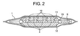
- the lock body 4 has four hooks 10 aligned in the above described lateral direction, that is, in a direction vertical to the longitudinal direction of the body fluid suction reservoir, and the hooks 10 extends vertically with respect to the surface of the second plate 12 so as to engage with an upward engagement surface 13 (Figs. 6 and 7) formed in a hole 2 of the first plate 11, and thereby the first plate 11 and second plate 12 are locked.
- the lock body 4 further includes a release part (or an operation part) 9 provided adjacently to one of the hooks 10.
- a release part or an operation part 9 provided adjacently to one of the hooks 10.
- the first plate 11 and second plate 12 includes portions 31 which protrude in a direction opposite to a direction in which the release part 9 is pushed, in at least two locations around the release part 9 of the lock body 4.
- the protruded portions 31 form a cutout portion 32 on the first plate 11 and the second plate 12, and the release part 9 is housed correspondingly to the cutout portion 32.
- the lock body 4 has flexibility (or elasticity) by which the lock body 4 can be deformed from a state in which the hooks 10 are secured to the first plate 11 as shown in Fig. 2 to a state in which the hooks 10 are not secured to the plate 11.
- the lock body 4 is required to have strength for locking the first plate 11 and the second plate 12 in a state in which the spring 3 is compressed. Therefore, when forming the lock body 4 as a single component, it is preferable to use high-rigidity engineering plastic, such as polyacetal or the like, as a material of the lock body 4. Since the lock body 4 has elasticity, the hooks 10 is adapted to receive force (return force) which urges the hooks 10 in a direction so as to engage with the first plate 11.
- Both the first plate 11 and the second plate 12 have thin-plate portions 18 (Figs. 5 and 6), and are constituted so as to be bent by the thin-plate portions 18 serving as a fulcrum in accordance with the extension of the spring 3.
- the lock body 4 has a thin-lock portion 19 which is bent correspondingly to the bend of the thin-plate portions 18.
- the release part 9 having the thin-lock portion 19 it is preferable to use a material which has large breaking elongation and is not easily cracked for the release part 9 having the thin-lock portion 19, and to connect the release part 19 to the lock 4 made of high-rigidity engineering plastic by means of fitting or the like.
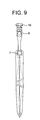
- the engagement surface 33 of the hook 10 may contact with the engagement surface 13 of the first plate 11 in parallel, however, by forming a protruded portion on front ends 20 and 14 of the engagement surfaces 13 and 33 as shown in Fig. 8, the risk of release of the lock body 4 in transit or storage can be further reduced.
- a holding part 16 may be provided adjacently to the fluid evacuate port lid 8 to fix the holding part 16 by hooking the holding part 16 to a suspension hole 15 of the bag 1, which is further preferable since the fluid evacuate port lid 8 does not get in the way when evacuating the fluid.
- the bag 1 may have a holding part attachment hole 40 for fixing the holding part 16, in addition to the suspension hole 15.
- the first plate 11 and the second plate 12 may be connected each other so as to be pivotable by means of a plate connecting member 17.
- the fluid evacuate port 7 is closed using the fluid evacuate port lid 8 to connect a drainage tube set to a patient to the fluid collecting port 5.
- the release part 9 of the lock body 4 is inserted toward a center of the fluid suction reservoir to release the engagement of the hooks 10 with the first plate 11.
- force for separating the first plate 11 and the second plate 12 from each other acts therein due to resilience of the spring 3, so that negative pressure is generated in the bag 1.
- body fluid of the patient is sucked and collected from a body cavity.
- the fluid evacuate port lid 8 is opened to discard the waste fluid stored in the bag 1.
- the lock body 4 may be flexible so that the hooks are urged in a direction (in a right direction in the drawings) to engage with the first plate 11 and thus, it is possible to press the first plate 11 and the second plate 12 to compress the spring 3 to return to the initial state shown Fig. 1 for resuction.
- the first plate 11 and the second plate 12 As a property requested for the first plate 11 and the second plate 12, it is raised that the first plate 11 and the second plate 12 have rigidity (high elastic modulus, creep resistance) for sufficiently resisting the stress of the compressed spring 3 for a long time, and are translucent or transparent for confirming condition and quantity of the contents, and further, it is important that the thin-plate portions 18 are not easily cracked (breaking elongation is large).
- high molecular weight polypropylene is most preferable as a material constituting the first plate 11 and second plate 12 as a single component, respectively.
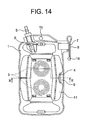
- Figs. 10 to 15 show a second embodiment of the body fluid suction reservoir of the present invention.
- the second embodiment is different from the first embodiment in that each of the first plate 11 and the second plate 12 has a shell part made of a material which is comparatively soft and has large breaking elongation.
- a component similar to that of the first embodiment is indicated by the same reference number.
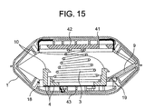
- a first plate is constituted by a shell part 41 which serves to hold an outline of the body fluid suction reservoir, and a core part 42 fixed on an inner side of the shell part 41 which core part 42 serves to directly receive the stress of the spring 3.
- the shell part 41 is provided with a thin-plate portion 18 (Fig. 15).
- the hooks 10 of the lock body 4 are engaged with an upper surface of the core part 42 to lock the first plate and the second plate as with the case of the first embodiment.
- the second plate 12 is constituted only by a shell part 43 serving to keep the outline of the body fluid suction reservoir so that the lock body 4 attached to the shell part 43 directly supports the spring 3.
- the lock body 4 of the second embodiment extends on the second plate over a wide area compared to the case of the lock body 4 of the first embodiment. Accordingly, it is unnecessary to set the hooks 10 in a central portion of the body fluid suction reservoir, and as shown in Fig. 11, it is possible to set two hooks 10 around each spring 3.
- This structure in which the lock body 4 supports the spring 3 is advantageous because the number of components can be further reduced and the cost can be suppressed. Accordingly, the spring 3 is held by the core part 42 and the lock body 4 in a compressed state.
- the engineering plastic having high elastic modulus and creep resistance as used for the first plate 11 and the second plate 12 of the first embodiment is normally crystalline plastic or fiber reinforced plastic which is opaque and has small breaking elongation.
- amorphous plastic which is transparent and has large breaking elongation has small rigidity in general, and thus, it is preferable to use, as a material of the core part 42, engineering plastic such as polyacetal, filler reinforced plastic, fiber reinforced plastic and the like, which have high elasticity and creep resistance, or metal such as aluminum or stainless steel, and to use, as a material of the shell part 41 provided with the thin-plate portion 18, plastic such as polyethylene or polypropylene having transparency and large breaking elongation.
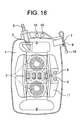
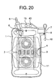
- Figs. 16 to 21 show a third embodiment of the body fluid suction reservoir of the present invention.
- the third embodiment is different from the first embodiment in that a first plate 11 and a second plate 12 are constituted by shell parts 41 and 43 made of a material which is comparatively soft and has large breaking elongation, and hard core parts 42 and 44 fixed on inner surfaces of the shell parts to directly receive the stress of springs 3, respectively.
- a component similar to that of the first and second embodiments is indicated by the same reference number with those.
- the first plate is constituted by the shell part 41 serving to keep an outline of the body fluid suction reservoir, and the core part 42 serving to directly receive the stress of the springs 3, and hooks 10 of a lock body 4 are engaged with an upper surface of the core part 42.
- the second plate is also constituted by the shell part 43 serving to keep the outline of the body fluid suction reservoir, and the core part 44 serving to directly receive the stress of the springs 3.
- the first plate 11 of the first embodiment shown in Fig. 2 is constituted by the shell part 41 and the core part 42
- the second plate 12 of the first embodiment is constituted by the shell part 43 and the core part 44.
- the first plate and the second plate by completely different components for each function, it is possible to constitute each part by a material suitable for each function, which makes it possible to broaden the width of material selection. That is, in the case of the third embodiment, since the springs 3 are supported by the core parts 42 and 44, it becomes possible that only the core parts 42 and 43 are constitute by a hard material.
- the engineering plastic such as polyacetal, filler reinforced plastic, fiber reinforced plastic and the like which have high elastic modulus and creep resistance, or metal such as aluminum or stainless steel
- plastic such as polyethylene or polypropylene having transparency and large breaking elongation as a material of the shell parts 41 and 43.
Landscapes
- Health & Medical Sciences (AREA)
- Heart & Thoracic Surgery (AREA)
- Vascular Medicine (AREA)
- Engineering & Computer Science (AREA)
- Anesthesiology (AREA)
- Biomedical Technology (AREA)
- Hematology (AREA)
- Life Sciences & Earth Sciences (AREA)
- Animal Behavior & Ethology (AREA)
- General Health & Medical Sciences (AREA)
- Public Health (AREA)
- Veterinary Medicine (AREA)
- External Artificial Organs (AREA)
Abstract
Description
Claims (18)
- A body fluid suction reservoir comprising a flexible bag, two plates for supporting the bag, and a spring put between the two plates, characterized in that
the body fluid suction reservoir further comprises a lock constituted by a hook, a release part, and a member different from the two plates, by which lock the spring is held in a compressed state between the two plates, the held state being able to be released. - The body fluid suction reservoir according to claim 1, wherein the lock is flexible, and is held by one of the plates so as to be deformable from a first state in which the hook engages with the other plate to a second state in which the hook is not engaged, and the hook is urged so as to be in the first state.
- The body fluid suction reservoir according to claim 2, wherein the hook moves in parallel with a surface of the one plate while the lock deforms from the first state to the second state.
- The body fluid suction reservoir according to any one of claims 1 to 3, wherein parts of the plates are protruded in a direction opposite to a direction of pushing the release part, in at least two locations around the release part of the lock.
- The body fluid suction reservoir according to any one of claims 1 to 4, wherein an engagement surface of the hook of the lock is provided with a portion protruding toward an engagement surface of the one plate on a tip side of the engagement surface of the hook, and the engagement surface of the one plate is provided with a portion protruding toward the engagement surface of the hook on a hole side of the engagement surface of the one plate.
- The body fluid suction reservoir according to any one of claims 1 to 5, characterized by comprising two or more springs arranged in a straight line in a longitudinal direction of the body fluid suction reservoir.
- The body fluid suction reservoir according to any one of claims 1 to 6, wherein the bag comprises a fluid evacuate port, a lid for the fluid evacuate port, and a suspension hole, and the lid for the fluid evacuate port is provided with a holding part by which the lid is held by the suspension hole.
- A body fluid suction reservoir comprising:a bag element having a fluid collecting port for taking in body fluid;a first plate and a second plate arranged in the bag element so as to face each other;an elastic member disposed between the first plate and the second plate; anda lock body attached to the second plate, whereinthe lock body comprises a hook part and an operation part for displacing the hook part,the hook part is adapted to engage with a hook engagement surface of the first plate to fix the first plate and the second plate, so that the elastic member is compressed and held between the first plate and the second plate, andthe operation part is operated to displace the hook part in parallel with a surface of the second plate, so that fixing of the first plate and the second plate are released to generate negative pressure in the bag element.
- The body fluid suction reservoir according to claim 8, characterized in that the lock body is elastically deformable, a part of the lock body is fixed to the second plate, thereby the operation part is operated so as to displace at least the hook part in parallel with the surface of the second plate, and the hook part returns to an initial position after the operation.
- The body fluid suction reservoir according to claim 8 or 9, characterized in that at least one of the first plate and the second plate comprises a cutout portion, and the operation part is located in the cutout portion or in correspondence with the cutout portion, so as to be positioned inside an outline of the body fluid suction reservoir.
- The body fluid suction reservoir according to any one of claims 8 to 10, wherein
the first plate comprises a first shell part forming a part of an outline of the body fluid suction reservoir, and a core part provided on a side of the shell part facing the second plate,
the second plate comprises a second shell part forming a part of the outline of the body fluid suction reservoir, and
at least a part of the lock body is located on a side of the second shell part facing the core part, so that the elastic member is compressed and held by the core part and at least the part of the lock body. - The body fluid suction reservoir according to claim 11, wherein the core part and the lock body are harder than the first shell part and the second shell part.
- The body fluid suction reservoir according to any one of claims 8 to 10, wherein
the first plate comprises a first shell part forming a part of an outline of the body fluid suction reservoir, and a first core part provided on a side of the first shell part facing the second plate,
the second plate comprises a second shell part forming a part of the outline of the body fluid suction reservoir, and a second core part provided on a side of the second shell part facing the first plate,
the hook engagement surface is configured by a surface of the first core part located on an opposite side to the second plate, and
the elastic member is compressed and held by the first core part and the second core part. - The body fluid suction reservoir according to claim 12, wherein the first core part and the second core part are harder than the first shell part and the second shell part.
- The body fluid suction reservoir according to claim 8, wherein the lock body comprises at least two hook parts.
- The body fluid suction reservoir according to claim 8, wherein the elastic member is a spring.
- The body fluid suction reservoir according to claim 14, comprising at least two springs arranged in a straight line between the first plate and the second plate.
- The body fluid suction reservoir according to claim 8, wherein
the bag element comprises a fluid evacuate port for evacuating the body fluid, a lid for the fluid evacuate port, and a suspension hole or a holding part attachment hole, and
the lid for the fluid evacuate port is provided with a holding part to be held by the suspension hole or the holding part attachment hole.
Applications Claiming Priority (5)
| Application Number | Priority Date | Filing Date | Title |
|---|---|---|---|
| JP2002346170 | 2002-11-28 | ||
| JP2002346170 | 2002-11-28 | ||
| JP2002363656 | 2002-12-16 | ||
| JP2002363656 | 2002-12-16 | ||
| PCT/JP2003/015100 WO2004047886A1 (en) | 2002-11-28 | 2003-11-26 | Body fluid suction and collection unit |
Publications (2)
| Publication Number | Publication Date |
|---|---|
| EP1566188A1 true EP1566188A1 (en) | 2005-08-24 |
| EP1566188A4 EP1566188A4 (en) | 2011-10-12 |
Family
ID=32396296
Family Applications (1)
| Application Number | Title | Priority Date | Filing Date |
|---|---|---|---|
| EP03811930A Withdrawn EP1566188A4 (en) | 2002-11-28 | 2003-11-26 | Body fluid suction and collection unit |
Country Status (7)
| Country | Link |
|---|---|
| US (2) | US7641639B2 (en) |
| EP (1) | EP1566188A4 (en) |
| JP (1) | JP4371055B2 (en) |
| KR (1) | KR100982067B1 (en) |
| CN (1) | CN101711895B (en) |
| TW (1) | TWI306768B (en) |
| WO (1) | WO2004047886A1 (en) |
Cited By (3)
| Publication number | Priority date | Publication date | Assignee | Title |
|---|---|---|---|---|
| EP1837044A1 (en) * | 2006-03-08 | 2007-09-26 | Covidien AG | Suction fluid collector for medical applications |
| GB2483292A (en) * | 2010-09-03 | 2012-03-07 | Apex Medical Corp | Collecting bag for a negative pressure wound therapy system |
| US8303555B2 (en) | 2010-08-31 | 2012-11-06 | Apex Medical Corp. | Soft collector for a negative pressure wound therapy system and its combination |
Families Citing this family (19)
| Publication number | Priority date | Publication date | Assignee | Title |
|---|---|---|---|---|
| KR100696431B1 (en) * | 2004-11-22 | 2007-03-19 | 메딕스얼라인 주식회사 | Biological Liquid Suction Device |
| CN101648037B (en) * | 2009-07-16 | 2011-11-16 | 宁波市鄞州云帆工程咨询有限公司 | Supercharged liquid sucking bag |
| US8172777B2 (en) * | 2009-09-14 | 2012-05-08 | Empire Technology Development Llc | Sensor-based health monitoring system |
| US20110238022A1 (en) * | 2010-03-24 | 2011-09-29 | Shayna Massi | Corporeal drainage system |
| AU2012302238B2 (en) * | 2011-08-31 | 2016-09-22 | Kci Licensing, Inc. | Inline storage pouches for use with body fluids |
| CN104083808A (en) * | 2014-08-04 | 2014-10-08 | 毕玉芳 | Simple stomach negative pressure drainage bag |
| KR101634331B1 (en) * | 2014-09-02 | 2016-07-08 | 권병수 | Medical suction device |
| KR101687341B1 (en) * | 2015-06-05 | 2016-12-16 | (주)에이치앤비메디텍 | Medical suction unit and fabrication method thereof |
| CN105056322A (en) * | 2015-09-07 | 2015-11-18 | 常熟市博洋医疗器械有限公司 | Disposable negative pressure drainage apparatus |
| JP7131742B2 (en) | 2016-09-29 | 2022-09-06 | メリット・メディカル・システムズ・インコーポレイテッド | A flexible member for receiving a vascular prosthesis and assisting in its deployment |
| EP4467111A3 (en) | 2017-03-15 | 2025-03-05 | Merit Medical Systems, Inc. | Transluminal stents |
| CN107551331B (en) * | 2017-09-14 | 2024-05-10 | 中国人民解放军第二军医大学 | Pressure limiting device for negative pressure drainage device for pleuroperitoneal cavity |
| JP6996230B2 (en) * | 2017-10-30 | 2022-01-17 | ニプロ株式会社 | Medical suction collector |
| CN108622540B (en) * | 2018-04-27 | 2019-09-13 | 河南省肿瘤医院 | A storage box for plasma testing |
| JP7367299B2 (en) * | 2018-09-24 | 2023-10-24 | ニプロ株式会社 | Medical suction liquid collection device and spring member for medical equipment |
| KR102340845B1 (en) * | 2019-06-28 | 2021-12-16 | 엄관용 | Medical Suction Unit |
| CN110464892A (en) * | 2019-08-31 | 2019-11-19 | 青岛大学附属医院 | A kind of drainage device used for nursing for ICU severe medicine section |
| WO2021165967A1 (en) * | 2020-02-19 | 2021-08-26 | Ronen Nahary | Expandable blood collecting apparatus |
| JP7468896B2 (en) * | 2020-07-28 | 2024-04-16 | 泉工医科工業株式会社 | Body fluid suction device |
Family Cites Families (15)
| Publication number | Priority date | Publication date | Assignee | Title |
|---|---|---|---|---|
| US3299839A (en) * | 1965-10-14 | 1967-01-24 | Nordbak Carl | Shelf device |
| JPS4921037Y1 (en) * | 1970-07-20 | 1974-06-05 | ||
| JPS5230098B2 (en) | 1972-06-16 | 1977-08-05 | ||
| US3889677A (en) | 1973-11-19 | 1975-06-17 | Int Paper Co | Self-contained fluid evacuator |
| US4429693A (en) | 1980-09-16 | 1984-02-07 | Blake L W | Surgical fluid evacuator |
| US4349015A (en) * | 1980-11-14 | 1982-09-14 | Physio-Control Corporation | Manually-actuable CPR apparatus |
| US4583972A (en) * | 1984-05-18 | 1986-04-22 | Complex, Inc. | Wound evacuator |
| JPS61131751A (en) | 1984-11-30 | 1986-06-19 | 住友ベークライト株式会社 | Medical suction liquid collector |
| US4981474A (en) * | 1988-02-16 | 1991-01-01 | Baxter Travenol Laboratories, Inc. | Body fluid drainage device |
| SE465704B (en) * | 1990-06-11 | 1991-10-21 | Hans Aake Stoeoep | PUMP TYPE PUMP DEVICE, INTENDED FOR ARTIFICIAL INHALATION |
| JPH04216138A (en) * | 1990-12-17 | 1992-08-06 | Hitachi Ltd | System installing method and computer system |
| US5551849A (en) * | 1994-04-29 | 1996-09-03 | Medtronic, Inc. | Medication delivery device and method of construction |
| US5496299A (en) * | 1994-09-21 | 1996-03-05 | C. R. Bard, Inc. | Suction reservoir |
| US5885261A (en) * | 1996-04-25 | 1999-03-23 | C. R. Bard, Inc. | Autotransfusion system and method |
| DE10233173B4 (en) | 2002-07-22 | 2006-03-23 | Bayer Industry Services Gmbh & Co. Ohg | Method for separating mercury from flue gases |
-
2003
- 2003-11-26 KR KR1020057008823A patent/KR100982067B1/en not_active Expired - Fee Related
- 2003-11-26 JP JP2004555054A patent/JP4371055B2/en not_active Expired - Fee Related
- 2003-11-26 WO PCT/JP2003/015100 patent/WO2004047886A1/en not_active Ceased
- 2003-11-26 CN CN2009102220325A patent/CN101711895B/en not_active Expired - Lifetime
- 2003-11-26 US US10/534,859 patent/US7641639B2/en not_active Expired - Fee Related
- 2003-11-26 EP EP03811930A patent/EP1566188A4/en not_active Withdrawn
- 2003-11-27 TW TW092133406A patent/TWI306768B/en not_active IP Right Cessation
-
2009
- 2009-03-13 US US12/403,505 patent/US7976521B2/en not_active Expired - Fee Related
Cited By (8)
| Publication number | Priority date | Publication date | Assignee | Title |
|---|---|---|---|---|
| EP1837044A1 (en) * | 2006-03-08 | 2007-09-26 | Covidien AG | Suction fluid collector for medical applications |
| KR100820414B1 (en) * | 2006-03-08 | 2008-04-08 | 코비디엔 아게 | Medical Suction Fluid Collector |
| US7468058B2 (en) | 2006-03-08 | 2008-12-23 | Tyco Healthcare Group Lp | Suction fluid collector for medical applications |
| AU2007200505B2 (en) * | 2006-03-08 | 2009-04-02 | Covidien Ag | Suction fluid collector for medical applications |
| CN101062432B (en) * | 2006-03-08 | 2010-04-21 | 舍伍德服务股份公司 | Medical Aspirated Fluid Collector |
| US8303555B2 (en) | 2010-08-31 | 2012-11-06 | Apex Medical Corp. | Soft collector for a negative pressure wound therapy system and its combination |
| GB2483292A (en) * | 2010-09-03 | 2012-03-07 | Apex Medical Corp | Collecting bag for a negative pressure wound therapy system |
| GB2483292B (en) * | 2010-09-03 | 2012-07-11 | Apex Medical Corp | Collector for a negative pressure wound therapy system and its combination |
Also Published As
| Publication number | Publication date |
|---|---|
| KR100982067B1 (en) | 2010-09-13 |
| CN101711895A (en) | 2010-05-26 |
| US20060015078A1 (en) | 2006-01-19 |
| US20090234330A1 (en) | 2009-09-17 |
| US7976521B2 (en) | 2011-07-12 |
| EP1566188A4 (en) | 2011-10-12 |
| TW200418540A (en) | 2004-10-01 |
| CN101711895B (en) | 2013-06-19 |
| US7641639B2 (en) | 2010-01-05 |
| JP4371055B2 (en) | 2009-11-25 |
| JPWO2004047886A1 (en) | 2006-03-23 |
| KR20050086694A (en) | 2005-08-30 |
| WO2004047886A1 (en) | 2004-06-10 |
| TWI306768B (en) | 2009-03-01 |
Similar Documents
| Publication | Publication Date | Title |
|---|---|---|
| US7976521B2 (en) | Body fluid suction reservoir | |
| JPH03126459A (en) | Automatic transfusion bag | |
| US20070219531A1 (en) | Suction Fluid Collector for Medical Applications | |
| US6053362A (en) | Can-breaker | |
| CN201015570Y (en) | Front cover clamping device of the dust collector | |
| CN100581597C (en) | Body fluid suction type reservoir | |
| JP7215059B2 (en) | medical suction device | |
| CN207511169U (en) | Multifunctional trash can | |
| JP4145889B2 (en) | Medical tools | |
| JP2008100750A (en) | Moisturizing container | |
| JP2000202021A (en) | Humor sucking-collecting apparatus | |
| JP3152450U (en) | Manual waste compressor | |
| CN209916811U (en) | Novel compensation type negative pressure drainage device | |
| CN219763245U (en) | Dust collection module, dust collection base station and automatic cleaning system | |
| JP2000262631A (en) | Humor suction and collection device | |
| CN221939044U (en) | Plastic partition support frame | |
| EP4509148A1 (en) | Breast milk collector and method | |
| JP2021101894A (en) | Medical suction device | |
| CN213310327U (en) | Internal medicine stethoscope storage device | |
| CN213283929U (en) | Hospital bed sheet fixer | |
| CN219750379U (en) | Penetration type space optimization plastic suction carrying device | |
| JP3061916B2 (en) | Body fluid suction collector | |
| CN212196668U (en) | Electronic sphygmomanometer storage box | |
| CN101045172B (en) | Medical appliance | |
| CN211195561U (en) | File bag convenient for teaching management |
Legal Events
| Date | Code | Title | Description |
|---|---|---|---|
| PUAI | Public reference made under article 153(3) epc to a published international application that has entered the european phase |
Free format text: ORIGINAL CODE: 0009012 |
|
| 17P | Request for examination filed |
Effective date: 20050518 |
|
| AK | Designated contracting states |
Kind code of ref document: A1 Designated state(s): AT BE BG CH CY CZ DE DK EE ES FI FR GB GR HU IE IT LI LU MC NL PT RO SE SI SK TR |
|
| RBV | Designated contracting states (corrected) |
Designated state(s): DE FR GB IT |
|
| A4 | Supplementary search report drawn up and despatched |
Effective date: 20110914 |
|
| RIC1 | Information provided on ipc code assigned before grant |
Ipc: A61M 1/00 20060101AFI20110908BHEP |
|
| 17Q | First examination report despatched |
Effective date: 20120330 |
|
| GRAP | Despatch of communication of intention to grant a patent |
Free format text: ORIGINAL CODE: EPIDOSNIGR1 |
|
| RAP1 | Party data changed (applicant data changed or rights of an application transferred) |
Owner name: SUMITOMO BAKELITE CO., LTD. |
|
| INTG | Intention to grant announced |
Effective date: 20150304 |
|
| RIN1 | Information on inventor provided before grant (corrected) |
Inventor name: SAKAGUCHI, YUKIHIKO, AKITA SUMITOMO BAKEL.CO.LTD. Inventor name: HARA, KEI, AKITA SUMITOMO BAKELITE CO., LTD. |
|
| STAA | Information on the status of an ep patent application or granted ep patent |
Free format text: STATUS: THE APPLICATION IS DEEMED TO BE WITHDRAWN |
|
| 18D | Application deemed to be withdrawn |
Effective date: 20150715 |